US9215656B2 - Self-contained data transfer channel - Google Patents
Self-contained data transfer channel Download PDFInfo
- Publication number
- US9215656B2 US9215656B2 US13/918,332 US201313918332A US9215656B2 US 9215656 B2 US9215656 B2 US 9215656B2 US 201313918332 A US201313918332 A US 201313918332A US 9215656 B2 US9215656 B2 US 9215656B2
- Authority
- US
- United States
- Prior art keywords
- data
- data transfer
- channel
- self
- user equipment
- Prior art date
- Legal status (The legal status is an assumption and is not a legal conclusion. Google has not performed a legal analysis and makes no representation as to the accuracy of the status listed.)
- Active, expires
Links
Images


Classifications
-
- H—ELECTRICITY
- H04—ELECTRIC COMMUNICATION TECHNIQUE
- H04W—WIRELESS COMMUNICATION NETWORKS
- H04W52/00—Power management, e.g. TPC [Transmission Power Control], power saving or power classes
- H04W52/02—Power saving arrangements
- H04W52/0209—Power saving arrangements in terminal devices
- H04W52/0212—Power saving arrangements in terminal devices managed by the network, e.g. network or access point is master and terminal is slave
- H04W52/0216—Power saving arrangements in terminal devices managed by the network, e.g. network or access point is master and terminal is slave using a pre-established activity schedule, e.g. traffic indication frame
-
- H—ELECTRICITY
- H04—ELECTRIC COMMUNICATION TECHNIQUE
- H04W—WIRELESS COMMUNICATION NETWORKS
- H04W52/00—Power management, e.g. TPC [Transmission Power Control], power saving or power classes
- H04W52/02—Power saving arrangements
- H04W52/0209—Power saving arrangements in terminal devices
- H04W52/0212—Power saving arrangements in terminal devices managed by the network, e.g. network or access point is master and terminal is slave
-
- H04W72/0406—
-
- H—ELECTRICITY
- H04—ELECTRIC COMMUNICATION TECHNIQUE
- H04W—WIRELESS COMMUNICATION NETWORKS
- H04W72/00—Local resource management
- H04W72/20—Control channels or signalling for resource management
-
- Y—GENERAL TAGGING OF NEW TECHNOLOGICAL DEVELOPMENTS; GENERAL TAGGING OF CROSS-SECTIONAL TECHNOLOGIES SPANNING OVER SEVERAL SECTIONS OF THE IPC; TECHNICAL SUBJECTS COVERED BY FORMER USPC CROSS-REFERENCE ART COLLECTIONS [XRACs] AND DIGESTS
- Y02—TECHNOLOGIES OR APPLICATIONS FOR MITIGATION OR ADAPTATION AGAINST CLIMATE CHANGE
- Y02D—CLIMATE CHANGE MITIGATION TECHNOLOGIES IN INFORMATION AND COMMUNICATION TECHNOLOGIES [ICT], I.E. INFORMATION AND COMMUNICATION TECHNOLOGIES AIMING AT THE REDUCTION OF THEIR OWN ENERGY USE
- Y02D30/00—Reducing energy consumption in communication networks
- Y02D30/70—Reducing energy consumption in communication networks in wireless communication networks
Definitions
- This application relates to communication systems and, more particularly, to a self-contained data transfer channel.
- GSM Global System for Mobile Communication
- UMTS Universal Mobile Telecommunication System
- 3GPP 3rd Generation Partnership Project
- LTE Long-Term Evolution
- LTE-A LTE-Advanced
- the information exchanged is packet-based, which means that the resources for transmission and reception of user data are allocated dynamically over time.
- signaling protocols have been developed which enable a mobile terminal to connect to a wireless network, transfer information, and then disconnect from the wireless network. These sequences typically incorporate the concepts of a) network access, b) packet data transfer setup, c) packet data transfer, and d) release of resources, or packet session tear-down. This is traditionally referred to as the call oriented approach to data transfer.
- MTC Machine type communication
- RACH random access channel
- the network moves the UE in and out of connected mode after each data burst.
- the signaling sequence that is required to access the wireless network may result in extremely high signaling overhead (compared to the actual amount of data exchanged).
- these extra signaling messages also consume UE battery power disproportionately.
- One option to reduce connection establishment signaling is to hold the UE in long term connected mode.
- the current design of mobile communication systems to achieve high data rates and spectral efficiencies impose higher cost as well as result in higher power consumption in the device in connected mode due to the need to support more complex operations on both the control plane as well as the user plane.
- decoding the current physical downlink control channel requires the devices to perform a search for their Downlink Control Information (DCI) amongst a large set of possibilities (e.g., 64 for 10 MHz) and the devices are expected to monitor the control channels while in connected mode. This procedure increases the complexity, cost, and power consumption at the UE.
- DCI Downlink Control Information
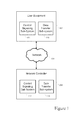
- FIG. 1 illustrates a system with user equipment coupled with a network controller through a network connection.
- FIG. 2 illustrates user equipment communicating through an uplink channel and a downlink channel.
- FIG. 3 illustrates a network controller communicating through an uplink channel and a downlink channel.
- FIG. 4 illustrates additional details of one implementation of user equipment.
- FIG. 5 illustrates a signaling sequence to enable wireless transmission of data between user equipment and a network controller.
- FIG. 6 illustrates downlink data grants in a control channel of a LTE system.
- FIG. 7 illustrates self-contained data channels with in-band signaling.
- FIG. 8 illustrates a quality of service channel selection mechanism
- FIG. 9 illustrates a modification to an allocated data transfer resource.
- FIG. 10 illustrates self-contained data channels with in-band signaling to implement a hybrid automatic repeat request (HARQ) acknowledgement and negative-acknowledgement exchange.
- HARQ hybrid automatic repeat request
- FIG. 11 illustrates a self-contained data channel with guards.
- FIG. 12 illustrates a channel identification index value for commands associated with a Low-Priority Channel (LPCH).
- LPCH Low-Priority Channel
- FIGS. 13-15 illustrate examples of control elements relevant to the LPCH.
- FIG. 16 illustrates a configuration information element for the LPCH.
- FIG. 17 illustrates configuration field descriptions for the LPCH.
- LPCH Low-Priority channel
- the LPCH is a contention-free hyper-low rate channel with loose synchronization and that is self-contained through use of in-band control signaling.
- the features of the LPCH simplify the user equipment (UE) process for transmitting low volume delay tolerant data.
- the low-priority low-volume data transmission may be predictable, and range from frequent (e.g., less than hourly) to infrequent (e.g., hourly or longer) to very infrequent (e.g., monthly or longer).
- the use of LPCH is tailored for such low cost UEs with low priority data and hence the emphasis is on power consumption reduction and low signaling overhead for connections rather than latency or throughput.
- the LPCH provides a slotted, repeating physical resource that requires very little overhead to set up and tear down.
- the LPCH may be unidirectional or bidirectional, and is optimized to carry small amounts of low-priority data, such as presence information or other machine-to-machine type information.
- the LPCH reduces or obviates the need for a separate control channel for some types of signaling by embedding most or all of the required control information within the LPCH itself.
- the LPCH allows the system to create a long term shared channel allocation that can use the control functions of hybrid automatic repeat requests (HARQ), scheduling requests (SR), buffer status reports (BSR), and channel quality indications (CQI) as in-band signaling within the LPCH without the use of separate control channels after the LPCH has been established. This allows the system to apportion very low quantities of its resources to serve the very low priority data.
- HARQ hybrid automatic repeat requests
- SR scheduling requests
- BSR buffer status reports
- CQI channel quality indications
- Retransmissions or feedback mechanisms in the LPCH are designed to not require any additional resources other than the LPCH (e.g., they may be performed through in-band signaling).
- the LPCH may be designed to provide a data channel whose entire control function is completely contained within the same channel after the LPCH is set up. As such, the in-band signaling of the LPCH is a good fit for low priority, low volume traffic applications.
- the self-contained signaling used by the LPCH may still be encoded (and subsequently decoded) more robustly than data within other previously configured allocations.
- the network controller function of this invention may be embodied in another UE.
- the LPCH is designed to carry both data (e.g., user plane data) and signaling for small infrequent or periodic transmissions.
- the amount of resources available to a UE in the LPCH depends on the amount of data that needs to be sent, and can be scaled in the time axis to keep the resources per unit time that an eNB has to expend under check. For example, given 10,000 UEs transmitting low priority data, 1 Resource Block (RB) in every frame of 10 milliseconds duration for the LPCH channel may be used to serve 10,000 UEs with a latency of less than an hour using only 0.2% of resources of a 10 MHz LTE system.
- the LPCH with its in-band signaling capability eliminates the need for a separate control channel during data transfer and also reduces overall control channel overhead required to serve a large number of UEs with low priority data.
- the LPCH implementations described herein may be relevant to Machine Type Communication (MTC).
- MTC Machine Type Communication
- the LPCH may be helpful to reduce the signaling overhead associated with the proliferation of MTC, especially for MTC of small low priority data packets.
- Machine type traffic encompasses a wide variety of traffic but may be considered to be traffic that is generated and consumed without much user interaction. MTC is expected to generate a significant amount of wireless traffic in the near future. MTC traffic may fall into various categories from highly delay sensitive and frequent transmissions (e.g., medical sensor reports) to highly delay tolerant infrequent transmissions of small data packets (e.g., smart meter readings).
- the LPCH is relevant to the issues of MTC, it is also relevant to other communication devices, applications, and technologies.
- the LPCH may also be applied to devices such as smartphones, for which the LPCH benefits would be particularly relevant with regard to the quality of service requirements of the associated applications running on the smartphones.
- FIG. 1 illustrates a system with user equipment 102 coupled with a network controller 106 through a network connection 104 .
- the user equipment 102 may serve to terminate a communication session for a user.
- the user equipment 102 may be a mobile device or wireless device, such as a mobile telephone, smartphone, tablet, personal digital assistant, handheld or laptop computer, or another device that has telecommunications capabilities.
- the user equipment 102 may be a device that is not transportable, such as a desktop computer, set-top box, smart meter (e.g., a gas or electricity utility usage meter with wireless communication capabilities), or network appliance.
- the network controller 106 may be a base station, network node (such as an eNB in an LTE network), wireless access point, or any other component of the wireless network. In another implementation, the network controller 106 may be resident to another user equipment device, such as in a device-to-device communication network.
- network node such as an eNB in an LTE network
- wireless access point or any other component of the wireless network.
- the network controller 106 may be resident to another user equipment device, such as in a device-to-device communication network.
- the network 104 enables the user equipment 102 and the network controller 106 to exchange data and control messages.
- the user equipment 102 includes a control signaling sub-system 108 and a data transfer sub-system 110 .
- the network controller 106 includes a control signaling sub-system 112 and a data transfer sub-system 114 .
- the control signaling sub-systems 108 and 112 may be programmed to create control signaling messages to control how the parties handle the data exchanges.
- the control signaling sub-systems 108 and 112 may exchange control signal messages to set up the LPCH introduced herein, modify the parameters of the LPCH after setup, or transfer other control information through the LPCH.
- control signaling sub-systems 108 and 112 send control signals across traditional control channels to set up and establish the LPCH, but then send all subsequent control messages as in-band signals in the LPCH until the LPCH is torn down.
- the data transfer sub-systems 110 and 114 may be programmed to create data packets to transmit information from a data storage buffer. Both data packets and control signals may be transferred between the user equipment 102 and the network controller 106 on the same channel, such as the LPCH, through the network 104 .
- FIG. 2 illustrates user equipment 102 communicating through a downlink channel 202 and an uplink channel 204 .
- the user equipment 102 receives data and control signals from one or more communication partners (e.g., the network controller 106 of FIG. 1 ) through the downlink channel 202 .
- the user equipment 102 also transmits data and control signals to one or more communication partners (e.g., the network controller 106 of FIG. 1 ) through the uplink channel 204 .
- the uplink and downlink channels 202 and 204 used by the user equipment 102 may be instances of the LPCH introduced herein.
- one of the uplink or downlink channels 202 and 204 may be an LPCH while the other is a traditional data transfer channel.
- the user equipment 102 includes one or more processors 206 , one or more memory devices 208 , and one or more input/output interfaces 210 .
- the input/output interfaces 210 may be used to connect the user equipment 102 with other devices or networks.
- the processor 206 may be a computer processor implemented as a central processing unit (CPU), microprocessor, microcontroller, application specific integrated circuit (ASIC), or a combination of circuits.
- the processor 206 is a specialized microprocessor with an architecture optimized for a specific application, such as a wireless channel management application, or a specific device, such as a mobile communication device (e.g., a smartphone, tablet computer, or smart meter).
- the memory device 208 may include a magnetic disc, an optical disc, RAM, ROM, DRAM, SRAM, Flash and/or any other type of computer memory.
- the memory device 208 is communicatively coupled with the computer processor 206 so that the computer processor 206 can access data stored on the memory device 208 , write data to the memory device 208 , and execute programs and modules stored on the memory device 208 .
- the memory device 208 includes one or more data storage areas 212 and one or more programs.
- the data and programs are accessible to the computer processor 206 so that the computer processor 206 is particularly programmed to implement the channel management and usage functionality of the LPCH system.
- the programs may include one or more modules executable by the computer processor 206 to perform the desired channel management and usage functions.
- the program modules may include one or more channel management/usage applications 214 that set up, manage, and use the LPCH.
- the channel management/usage applications 214 may include one or more data source applications that generate data for transfer through the uplink channel 204 .
- the channel management/usage applications 214 may include one or more management applications that control the transmission of the source application data, such as by sending and receiving control signals with other communication partners.
- the memory device 208 may also store additional programs, modules, or other data to provide additional programming to allow the computer processor 206 to perform the functionality of the user equipment 102 .
- the described modules and programs may be parts of a single program, separate programs, or distributed across multiple memories and processors. Furthermore, the programs and modules, or any portion of the programs and modules, may instead be implemented in hardware or circuitry.
- FIG. 3 illustrates a network controller 106 communicating through an uplink channel 302 and a downlink channel 304 .
- the network controller 106 receives data and control signals from one or more communication partners (e.g., the user equipment 102 of FIG. 1 ) through the uplink channel 302 .
- the network controller 106 also transmits data and control signals to one or more communication partners (e.g., the user equipment 102 of FIG. 1 ) through the downlink channel 304 .
- the uplink and downlink channels 302 and 304 used by the network controller 106 may be instances of the LPCH introduced herein.
- one of the uplink or downlink channels 202 and 204 may be an LPCH while the other is a traditional data transfer channel.
- FIG. 1 illustrates a network controller 106 communicating through an uplink channel 302 and a downlink channel 304 .
- the network controller 106 receives data and control signals from one or more communication partners (e.g., the user equipment 102 of FIG. 1 ) through
- FIG. 3 includes one or more processors 306 , one or more memory devices 308 (including one or more data storage areas 312 and one or more programs, such as the channel management/usage application(s) 314 ), and one or more input/output interfaces 310 .
- the descriptions above regarding the structure and function of components 206 , 208 , 210 , 212 , and 214 in connection with FIG. 2 are incorporated herein for the corresponding components 306 , 308 , 310 , 312 , and 314 of FIG. 3 .
- the operation of the components in FIG. 3 is from the perspective of the network controller 106 instead of the user equipment 102 .
- FIG. 4 is a block diagram of one implementation of the user equipment 102 programmed with a channel management application that sets up, manages, and/or uses the LPCH.
- the user equipment 102 includes a number of components, such as a main processor 402 that controls the overall operation of the user equipment 102 .
- Communication functions, including data and voice communications, are performed through a communication subsystem 404 .
- the communication subsystem 404 receives messages from and sends messages to wireless network 405 .
- the communication subsystem 404 may be configured in accordance with Universal Mobile Telecommunications System (UMTS) technology using the UMTS Terrestrial Radio Access Network (UTRAN) or Long Term Evolution (LTE) technology using Evolved UTRAN (E-UTRAN).
- UMTS Universal Mobile Telecommunications System
- UTRAN UMTS Terrestrial Radio Access Network
- LTE Long Term Evolution
- E-UTRAN Evolved UTRAN
- the communication subsystem 404 may be configured in accordance with the Global System for Mobile Communication (GSM) and General Packet Radio Services (GPRS) standards. In other implementations, the communication subsystem 404 may be configured in accordance with other mobile communication protocols.
- the wireless link connecting communication subsystem 404 with wireless network 405 represents one or more different radio frequency (RF) channels, operating according to defined protocols specified for the particular communication technologies being employed. These channels may be capable of supporting both circuit switched voice communications and packet switched data communications.
- RF radio frequency
- wireless networks also may be associated with the user equipment 102 in various implementations.
- the different types of wireless networks that may be employed include, for example, data-centric wireless networks, voice-centric wireless networks, and dual-mode networks that can support both voice and data communications over the same physical base stations.
- Combined dual-mode networks include, but are not limited to, Code Division Multiple Access (CDMA) or CDMA2000 networks, GSM/GPRS networks, third-generation (3G) networks like EDGE and UMTS, fourth-generation (4G) networks, and Long Term Evolution (LTE) networks.
- Examples of other voice-centric data networks include Personal Communication Systems (PCS) networks like GSM and Time Division Multiple Access (TDMA) systems.
- PCS Personal Communication Systems
- TDMA Time Division Multiple Access
- Main processor 402 interacts with additional subsystems such as random access memory (RAM) 406 , flash memory 408 , display 410 , auxiliary input/output (I/O) subsystem 412 , data port 414 , keyboard 416 , speaker 418 , microphone 420 , short-range communications 422 , and other device subsystems 424 .
- RAM random access memory
- I/O auxiliary input/output subsystem 412
- data port 414 keyboard 416
- speaker 418 speaker 418
- microphone 420 microphone 420
- short-range communications 422 and other device subsystems 424 .
- Some of the subsystems of the user equipment 102 perform communication-related functions, whereas other subsystems may provide resident or on-device functions.
- display 410 and keyboard 416 may be used for both communication-related functions, such as entering a text message for transmission over network 405 , and device-resident functions such as a calculator or task list or the channel management system.
- the user equipment 102 may send and receive communication signals over wireless network 405 after required network registration or activation procedures have been completed.
- Network access may be associated with a subscriber or user of the user equipment 102 .
- the user equipment 102 may use a SIM card/RUIM 426 (i.e., Subscriber Identity Module or a Removable User Identity Module) to be inserted into a SIM/RUIM interface 428 in order to communicate with a network.
- SIM card or RUIM 426 is one type of a conventional smart card that can be used to identify a subscriber of the user equipment 102 and to personalize the user equipment 102 , among other things.
- SIM card/RUIM 426 may include a processor and memory for storing information.
- the SIM card/RUIM 426 may enable a subscriber to access subscribed service, such as web browsing and messaging such as e-mail, voice mail, Short Message Service (SMS), and Multimedia Messaging Services (MMS), point of sale, field service, and sales force automation.
- subscribed service such as web browsing and messaging such as e-mail, voice mail, Short Message Service (SMS), and Multimedia Messaging Services (MMS), point of sale, field service, and sales force automation.
- SIM card/RUIM 426 is inserted into SIM/RUIM interface 428 , it is coupled to main processor 402 .
- user identification information may be programmed into flash memory 408 .
- the user equipment 102 may be a battery-powered device that includes battery interface 432 for receiving one or more rechargeable batteries 430 .
- battery 430 may be a smart battery with an embedded microprocessor.
- Battery interface 432 may be coupled to a regulator, which assists battery 430 in providing power V+ to the user equipment 102 .
- future technologies such as micro fuel cells or photovoltaic cells, may provide the power to the user equipment 102 .
- the user equipment 102 also includes operating system 434 and other programs 436 .
- Operating system 434 and programs 436 may be implemented as software components that are run by main processor 402 .
- Operating system 434 and programs 436 typically are stored as program code on a media readable by a processor, such as main processor 402 .
- Such readable storage media may include a persistent storage device, such as flash memory 408 , which may alternatively be a read-only memory (ROM) or similar storage element.
- flash memory 408 such as a persistent storage device
- ROM read-only memory
- portions of operating system 434 and programs 436 such as specific device applications, or parts thereof, may be temporarily loaded into a volatile storage device, such as RAM 406 .
- Other software components also may be included, as is well known to those skilled in the art.
- Programs 436 that control basic device operations, including data and voice communication applications, will normally be installed on the user equipment 102 during its manufacture.
- Other programs 436 include message application 438 .
- Message application 438 can be any suitable software program that allows a user of the user equipment 102 to send and receive electronic messages. Messages that have been sent or received by the user are typically stored in flash memory 408 of the user equipment 102 , or some other suitable storage element in the user equipment 102 . In some implementations, some of the sent and received messages may be stored remotely from the user equipment 102 , such as in a data store of an associated host system.
- Programs 436 may further include device state module 440 , Personal Information Manager (PIM) 442 , and other suitable modules.
- Device state module 440 provides persistence, i.e., device state module 440 ensures that some device data is stored in persistent memory, such as flash memory 408 , so that the data is not lost when the user equipment 102 is turned off or loses power.
- PIM 442 includes functionality for organizing and managing data items of interest to the user, such as, but not limited to, e-mail, contacts, calendar events, voice mails, appointments, and task items.
- the user equipment 102 also includes connect module 444 , and IT policy module 446 . Connect module 444 implements the communication protocols that are used by the user equipment 102 to communicate with the wireless infrastructure and any host system, such as an enterprise system.
- Connect module 444 may include a set of Application Program Interfaces (APIs) that can be integrated with the user equipment 102 to allow the user equipment 102 to use any number of services associated with an enterprise system.
- IT policy module 446 receives IT policy data that encodes the IT policy. IT policy module 446 then ensures that the IT policy data is authenticated by the user equipment 102 . The IT policy data can then be stored in flash memory 406 in its native form.
- Other types of programs or software applications also may be installed on the user equipment 102 . These software applications may be third party applications, which are added after the manufacture of the user equipment 102 . Examples of third party applications include games, calculators, utilities, and the like.
- the user equipment 102 is also programmed with a channel management application 448 that enables the user equipment 102 to set up and control the usage of the LPCH for data transfers to and/or from the user equipment 102 .
- the channel management application 448 may include one or more stand-alone modules, or may be implemented, in whole or in part, as part of another module.
- the channel management application 448 may be executed by the processor 402 when necessary to set up or control the usage of the LPCH for data transfers.
- FIG. 5 illustrates a signaling sequence to enable wireless transmission of data between user equipment (e.g., a mobile device) and a network controller.
- the implementation of FIG. 5 illustrates a LTE signaling sequence.
- the user equipment initiates the network access via the Random Access procedure and this procedure gives the network an idea of the identity of the user equipment, upon which the network can assign radio resources to that mobile device for subsequent data transfer.
- the user equipment initiates a network entry with a request for network access 502 on the RACH.
- the network responds with an assignment 504 of a control channel to the user equipment.
- the user equipment will send a request 506 on the control channel to the network requesting certain radio link resources.
- the network will respond with an assignment 508 of radio resources to the user equipment.
- the user equipment and network may then communicate 510 using the assigned radio resources.
- the user equipment and network may negotiate another data transfer allocation through steps 512 , 514 , and 516 .
- the user equipment and network communicate using control channels to set up the data channel in a traditional manner.
- this signaling sequence or functionality could be modified by using the self-contained LPCH procedures and in-band control signaling after the LPCH is setup by the user equipment and network, as discussed below in connection with FIG. 7 .
- FIG. 6 illustrates downlink data grants in a control channel of a LTE system. Specifically, FIG. 6 shows how low data rate, low priority bursts of data may be treated in LTE using separate control channels instead of using the in-band signaling of the self-contained LPCH introduced herein.
- FIG. 6 illustrates a physical downlink control channel (PDCCH) 602 and a physical downlink shared channel (PDSCH) 604 used by multiple user equipment devices (labeled UE1-UE4).
- PDCCH physical downlink control channel
- PDSCH physical downlink shared channel
- the network assigns small downlink grants 608 , 612 , 616 , and 620 for each of the user equipment devices UE1-UE4.
- the data grants 608 , 612 , 616 , and 620 indicate the scheduled downlink transmission for that UE, separated by long periods where no grants are needed (due to the low frequency of the data). While the grants can be tailored to fit the data requirements of the UEs, the system still incurs the overhead of a control channel grant in each subframe that has data addressed to the given UE.
- uplink grants 606 , 610 , 614 , and 618 are assigned per UE on the PDCCH for future uplink transmission. This requires the UE to periodically monitor the PDCCH for such grants, which results in unnecessary power consumption at the UE.
- Discontinuous reception allows the system to configure the UE to be actively receiving periodically in a discontinuous fashion.
- the power consumption of a user device in connected mode may be reduced by use of DRX time-domain patterns (known to both the UE and the eNB) defining whether or not the UE is expected to activate its receiver and monitor a given subframe for the presence of downlink or uplink assignments on PDCCH.
- DRX time-domain patterns known to both the UE and the eNB
- user-plane communications are not possible in the downlink and the UE may enter a DRX mode to reduce its power consumption.
- the DRX patterns and duty cycles vary according to the operation of certain timers, some of which are triggered by data activity.
- a DRX inactivity timer is reset to an initial value and restarted each time an assignment is received (via PDCCH) for a new uplink or downlink data packet.
- the timer While the timer is running, the UE is expected to actively monitor all downlink subframes.
- the timer expires (i.e. there have been no uplink or downlink assignments for new data for a defined period of time)
- the DRX pattern may change in order to allow the UE to sleep for an increased proportion of subframes.
- UE power consumption may be reduced.
- the UE is still expected to use control channels of physical uplink control channel (PUCCH) and monitor the PDCCH (although less frequently). Furthermore, the DRX ON and OFF times are not fixed and the ON time is extended as long as there are pending HARQ retransmissions. Therefore, even small data transmissions incur variable spectrum cost of control channel due to PDCCH and PUCCH allocations as well as power cost due to the UE being required to monitor the downlink control channels.
- PUCCH physical uplink control channel
- FIG. 7 illustrates the use of self-contained data channels with in-band signaling. Specifically, FIG. 7 illustrates the use of the LPCH introduced herein for uplink and downlink data transfer.
- FIG. 7 illustrates a downlink and uplink control and data channels, including PDCCH 702 , PDSCH 704 , PUCCH 706 , and PUSCH 708 .
- the channels are used by multiple user equipment devices (labeled UE1-UE4).
- the network assigns small downlink grants (i.e., data transfer resources) 718 , 720 , 722 , and 724 on the PDSCH 704 for each of the user equipment devices UE1-UE4.
- the network also assigns small uplink grants (i.e., data transfer resources) 734 , 736 , 738 , and 740 on the PUSCH 708 for each of the user equipment devices UE1-UE4.
- the data grants indicate the scheduled downlink and uplink transmission for that UE, separated by long periods where no grants are needed (due to the low frequency of the data).
- the LPCH implementation is shown as already having been set up for uplink and downlink communication between the UEs and a network controller.
- the UEs and network controller set up the LPCH implementation of FIG. 7 by exchanging control messages over traditional control channels. For example, to initially set up the LPCH between UE1 and the network controller, UE1 may send a request for resources over an uplink control channel to the network controller. This message may be similar to requests 506 and 512 of FIG. 5 . In response, the network controller will determine what resources are necessary for UE1's desired communication traffic. The UE may explicitly request a LPCH channel to be setup or the network controller may decide that an LPCH channel is appropriate based on some predetermined set of rules.
- These rules may include determination of: a type of the device requesting the resources, a type of application requesting the resources, knowledge of the data rates/frequencies of data exchange, device location, subscription type, time of day, congestion/traffic rate in the cell, and the like. If LPCH is deemed to be appropriate for the intended traffic, then the network controller will assign resources to UE1 according to the LPCH configuration. The network controller will then notify UE1 of the assigned resources through a control signal in the downlink control channel. This message may be similar to assignment notifications 508 and 514 of FIG.
- the configuration information element for the LPCH is shown and described in FIGS. 16 and 17 .
- FIG. 7 illustrates in-band control signals 710 , 712 , 714 , and 716 in the PDSCH 704 and in-band control signals 726 , 728 , 730 , and 732 in the PUSCH 708 .
- the PDCCH 702 and PUCCH 706 are not used for the control signals exchanged between the UE and network controller.
- control signals are exchanged without using a separate control channel (e.g., the PDCCH 702 and PUCCH 706 ) between set-up and tear-down of the self-contained data channel (e.g., the LPCH implementation of the PDSCH 704 and PUSCH 708 ).
- a separate control channel e.g., the PDCCH 702 and PUCCH 706
- the self-contained data channel e.g., the LPCH implementation of the PDSCH 704 and PUSCH 708 .
- a single grant that contains all signaling in the LPCH allows the system to significantly simplify the UE processing requirements.
- the UE using LPCH may activate its radio frequency font end and its inverse fast Fourier transforms to receive and transmit only in the part of the sub band where the LPCH allocation is configured.
- a UE that has an LPCH grant contained in the center six Resource Blocks (RBs) of the band can significantly reduce its communications processing by receiving and transmitting data in only those RBs at the prescribed times. This will simplify the receiver processing requirements and hence associated complexity.
- FIG. 7 illustrates an example where the LPCH is allocated in the center 6 RBs of a LTE deployment with 50 total available RBs in the uplink and downlink channels.
- LPCH grants may have fixed patterns (e.g., periodic) with long durations expected between successive grants.
- the recurrence of grants may be several minutes apart or hours apart for smart meter applications.
- the LPCH grants may be provided for both uplink and downlink.
- the allocations are expected to be set for long periods of time. Because the data carried in them is highly latency tolerant, the lack of a prompt grant is acceptable.
- the periodicity of the grant may be chosen such that there is a high probability that some data is available (either in downlink or uplink) and is awaiting transmission when the channel is available.
- this periodicity can be chosen based on the application type (e.g., smart meter applications sending periodic updates at known intervals/periodicities), device type, device location, subscription type (e.g., subscribers paying higher tariffs could be allocated a channel with more frequent resources), time of day, congestion/traffic rate in the cell, and the like.
- the fixed periodicity mechanism is appropriate because the applications involved are the type for which the periodicity can be predicted accurately due to known transmission schedules, such as in smart meters. Since the allocation of the channel is periodic and configured such that there is no contention, there is no need for dynamic signaling of grants in case of LPCH. This significantly reduces the PDCCH and PUCCH (e.g., scheduling request) resource load compared to the current dynamic way in which resources are allocated in case of LTE.
- PDCCH and PUCCH e.g., scheduling request
- the system may configure the LPCH periodic resources by specifying the allocated RBs and the periodicity of the grant.
- the connected mode UEs that have low priority data may be configured to use specific RBs and periodicity for uplink and/or downlink by using radio resource control (RRC) messages for initial setup.
- RRC radio resource control
- FIG. 7 illustrates one implementation of the LPCH in a LTE system. In this case, the system avoids the control channel grant overhead as compared to the system shown in FIG. 6 .
- the allocated resource may be an appropriately sized chunk of time, frequency, and code orthogonal to other allocations.
- the periodicity of the resource may be chosen to ensure maximum utilization, such that data is likely to be ready for transmission when the grant becomes available for the UE. However, if the UE has no data in downlink or uplink, the resource may be left unused. In this case, the UE may be allowed to send feedback information like channel quality reports or other such information instead of leaving the resource unused.
- the network controller e.g., eNB
- the LPCH data bearers may be mapped into RLC transparent mode (TM), where Automatic Repeat Request (ARQ) is disabled and it is left to the higher layer protocols to detect errors. Note however, that signaling RBs may still use RLC acknowledged mode (AM).
- TM RLC transparent mode
- ARQ Automatic Repeat Request
- AM RLC acknowledged mode
- FIG. 7 illustrates the grants in uplink and downlink as symmetric
- the uplink allocations may be more numerous than the downlink allocations, or vice versa.
- Asymmetric allocations may be used for applications with asymmetric traffic.
- a smart meter may require a small set of uplink allocations every few hours and even less frequent downlink allocations.
- the timing and size of the grants may incorporate sufficient robustness to not require HARQ retransmissions, CQI indications, or timing corrections.
- the current LTE system is designed around the premise that connected mode is used only for UEs with immediate data activity. Therefore, a common assumption is that on entering RRC connected mode, a user will be semi-statically assigned (usually for the duration of the connected mode stay) dedicated scheduling request (SR) resources on PUCCH for the purposes of informing the eNB of the UEs need to transmit data on PUSCH, subsequent to a new arrival of data and having previously had an empty transmission buffer.
- SR dedicated scheduling request
- the current LTE system also allows the UE to use physical random access channel (PRACH) resources to send the scheduling requests.
- PRACH physical random access channel
- the uplink data is semi-statically scheduled and is available for the UE to send its data whenever the resource is available.
- the UE may include a medium access control (MAC) buffer status report (BSR) header field in the transmitted data burst.
- the BSR may be sent as an in-band signal within the LPCH.
- the BSR may indicate to the network that there is more data available to send and the network may choose to increase the size of the LPCH resource at the next available resource. While this mechanism will have a higher latency than a scheduling request, the applications targeted by the LPCH may not need low latency.
- the overall system resources may be better used for more latency sensitive applications or UEs due to the saved scheduling request and PUCCH resources.
- the uplink resources reserved for UE CQI feedback could be eliminated as well by using robust modulation and coding format and relying on higher layer error control.
- the CQI feedback may be sent punctured in the physical layer resources that carry the LPCH data allocation or in a new CQI MAC CE (shown in FIG. 15 ) that can be sent along with data in the LPCH data allocation.
- the scheme of which physical layer resources carry the control information and which resources carry the data information can be set up during the setup of the LPCH and modified using in band signaling.
- the channel quality reports are only valid for a limited duration of time. This is typically dependent on the coherence time of the channel which in turn depends on the speed of the UE.
- the CQI reporting may not be as useful. However, for LPCH channels with shorter repeating periodicities, CQI reporting may be considered.
- the eNB may choose to switch the CQI reporting ON or OFF for an LPCH channel based on the periodicity of the channel. This may be based on a set of predetermined rules, may be dynamically configured by the network, or may be implicitly linked to the periodicity of the LPCH channel and/or the UE speed.
- FIG. 8 illustrates a quality of service channel selection mechanism.
- a quality of service (QoS) analyzer 802 may determine whether to set up or use the LPCH or a standard higher priority channel structure to transfer data. For example, at step 804 , the QoS analyzer 802 detects the traffic and sets up the LPCH, if the traffic is appropriate for the LPCH. When the application, or its proxy, sets the quality of service to indicate (1) low priority, and (2) small data size (e.g., less than 64 octets or some other predetermined or dynamic threshold), the quality of service analyzer 802 detects this condition and selects the appropriate radio bearer (i.e., LPCH in this case).
- the appropriate radio bearer i.e., LPCH in this case
- FIG. 8 also shows a radio link control (RLC) layer 806 performing LPCH mode selection control at step 812 , a medium access control (MAC) layer 808 generating LPCH MAC control elements at step 814 , and a physical (PHY) layer 810 mapping LPCH user and control data onto physical resources at step 816 .
- RLC radio link control
- MAC medium access control
- PHY physical
- FIG. 9 illustrates a modification to an allocated data transfer resource.
- FIG. 9 illustrates a modification to an allocated data transfer resource.
- UE1 is initially allocated a data grant 906 .
- the signaling message 908 changes the initial data grant 906 into a new data grant 910 that is different than the initial data grant 906 .
- the signaling message 908 provides an identification of the new data grant 910 to UEI.
- the new data grant 910 may be a completely new data grant or a modified version of the previous data grant. In the implementation of FIG. 9 , the new data grant 910 is larger than the initial data grant 906 .
- the LPCH is therefore not constrained to be uniform for all UEs or subframes.
- the allocation may be conveyed in a MAC Control Element (CE) or an RRC signal (e.g., information element or message).
- CE MAC Control Element
- RRC signal e.g., information element or message.
- the MAC message defined in FIG. 13 is used to reallocate the RBs using the RB assignment bits otherwise sent in the PDCCH DCI and the periodicity for LPCH.
- the grant may be punctured in the REs of the LPCH RBs. This would allow the grant to be coded more robustly than the data.
- FIG. 10 illustrates self-contained data channels with in-band signaling to implement a hybrid automatic repeat request (HARQ) acknowledgement (ACK) and negative-acknowledgement (NACK) exchange.
- HARQ is the process of combining (in a receiver) a first version of a signal with a second (retransmitted) version of a signal, and subsequently attempting to decode the combined signal.
- HARQ is a physical layer mechanism that is used in a number of mobile communication systems to improve the reliability and efficiency of the layer 1. This is distinct from ARQ in which the first and second versions are not combined.
- positive or negative acknowledgements of uplink transmissions are transmitted by the eNB on a downlink physical channel termed the Physical Hybrid ARQ Indicator Channel (PHICH).
- PHICH Physical Hybrid ARQ Indicator Channel
- Synchronous HARQ is used in LTE uplink, meaning that a retransmission (triggered in the UE by receipt of NACK on PHICH from the eNB) is sent on the same uplink resources (as the previous failed transmission) after a predetermined time period has elapsed since receipt of the NACK.
- the NACK on PHICH therefore implicitly reallocates the uplink resources for the purposes of the retransmission.
- the control information related to HARQ ACK/NACK in uplink is either sent on the PUCCH or the information is multiplexed with the data on the PUSCH when PUSCH transmission is present.
- HARQ ACK/NACK may be sent in-band in the LPCH data allocation in a new ACK/NACK MAC CE.
- the DL and UL HARQ ACK/NACK is punctured in the resource elements inside the UL and DL LPCH resource blocks respectively.
- the HARQ protocol as in LTE is altered in case of LPCH, wherein the upcoming periodic allocations in the opposite direction are used to convey the in band ACK/NACK feedback instead of using a separate control channel.
- the coding of the ACK/NACK may be made robust within the repeating periodic allocations.
- the in-band HARQ feedback transmission may increase the round trip time for retransmissions (based on the periodicity of the LPCH resources), the applications for which use the LPCH mechanism may not require low latency. Further, for asymmetric traffic, in a given LPCH transmission, several packets (received in the opposite direction) may be ACK/NACKed in one delayed ACK/NACK message. This reduces the control signaling overhead further.
- only one HARQ process may be employed. This is suitable for applications that send small packets of infrequent data that do not benefit from multiple HARQ processes, because there is too little data that need not be delivered in parallel.
- the HARQ feedback from the UE for the transport block that was transmitted in the downlink LPCH is sent in the subsequent uplink LPCH allocation.
- the same alternating sequence can be used in the uplink direction as well.
- FIG. 10 illustrates this in UEs 1 and 2.
- the HARQ ACK/NACK for DL data for UE1 sent in subframe n is sent by the UE in subframe n+P, where P is the periodicity of the allocations for UE1.
- the ACK/NACK corresponding to a particular downlink data transmission is shown by arrows 1002 , 1004 , and 1006
- the ACK/NACK corresponding to a particular uplink data transmission is shown by arrows 1008 , 1010 , and 1012
- Downlink retransmissions, when indicated as needed by a NACK are sent in the next downlink allocation for the UE (shown by dotted line 1014 )
- the uplink retransmissions when indicated as needed by an uplink NACK are sent in the next uplink allocation for the UE (shown by dotted line 1016 ).
- the maximum throughput achievable by a UE will also be restricted because of the single HARQ process because the transmitter will not be able to pipeline new data transmissions while waiting for an ACK/NACK for a pending data transmission.
- Throughput is however not a metric that is materially important for low priority applications that will use LPCH.
- the allocations in the uplink and downlink need not be sized similarly in some cases. Indeed, the size of the allocations may be changed be suitable to the applications and their directionality by signaling methods described above.
- more than one HARQ process may be used within the LPCH, where each allocation is for a new transmission or a retransmission of one particular HARQ process.
- the sequence number and the HARQ process number may be explicitly signaled via in band signaling.
- the process numbers are implicitly defined as a function of the grant number.
- FIG. 11 illustrates a self-contained data channel with guards.
- LPCH allows the UEs to send data with looser time synchronization requirements.
- the time alignment provided at setup time is adequate.
- the LPCH provides guard periods (or longer Cyclic Prefix (CP)) and suitable guard bands to avoid the overhead of giving each of the very low priority UEs the precise time synchronization as the high priority UEs in the system. For example, static devices like smart meters would be able to use the resource without the additional guard periods while more mobile UEs could use the resource with additional guard periods to avoid interference in the uplink.
- CP Cyclic Prefix
- LPCH Physical Downlink Control Channel
- SRS sounding reference signals
- TA Time Alignment
- the UE may still synchronize to the downlink timing. Further, time alignment for the UL may be determined by using in-band reference signals that are present in LPCH transmissions.
- any uplink timing corrections that are required may be sent by the eNB in time alignment commands sent within the LPCH.
- the LPCH may also be configured with time guards 1102 and/or frequency guards 1104 to allow for looser time alignment than dynamic data.
- the appropriately dimensioned guard sub channels 1104 and guard times 1102 may be inserted in the LPCH resources depending upon the expected error in time and frequency that needs to be tolerated in LPCH.
- FIG. 12 illustrates a channel identification index value for commands associated with a Low-Priority Channel (LPCH).
- the index value 11010 may be reserved for LPCH specific downlink commands and the index value 11000 may be reserved for LPCH specific uplink commands.
- FIGS. 13-15 illustrate examples of control elements relevant to the LPCH.
- a MAC subheader with the unique logical channel identification (LCID) indicates that the payload is a MAC control element.
- the MAC control element then could be coded in one of the following ways as shown in FIG. 13 or FIG. 14 to indcate reallocated LPCH resources.
- the reallocated RBs use the 11 bits in the same format as PDCCH DCIs filed indicating RB allocation.
- FIG. 13 Low-Priority Channel
- FIG. 13 illustrates a LPCH reallocation CE to indicate new RBs (i.e., to modify the frequency location of the LPCH resources).
- FIG. 14 illustrates a LPCH reallocation CE to indicate new periodicity (i.e., to modify the time at which the LPCH resource occur).
- an new uplink MAC control element could be defined to send inband uplink control information like channel quality information (as shown in FIG. 15 ).
- FIG. 16 illustrates a configuration information element for the LPCH.
- the IE LPCH-Config is used to specify the LPCH configuration.
- the network controller may send the LPCH-Config element to the UE to instruct the UE to use the features of the LPCH for subsequent data and control signal transfers.
- the LPCH-Config element instructs the UE to use the in-band control signaling features of the LPCH.
- FIG. 17 illustrates configuration field descriptions for the LPCH.
- Each of the processes described herein may be encoded in a computer-readable storage medium (e.g., a computer memory), programmed within a device (e.g., one or more circuits or processors), or may be processed by a controller or a computer. If the processes are performed by software, the software may reside in a local or distributed memory resident to or interfaced to a storage device, a communication interface, or non-volatile or volatile memory in communication with a transmitter.
- the memory may include an ordered listing of executable instructions for implementing logic.
- Logic or any system element described may be implemented through optic circuitry, digital circuitry, through source code, through analog circuitry, or through an analog source, such as through an electrical, audio, or video signal.
- the software may be embodied in any computer-readable or signal-bearing medium, for use by, or in connection with an instruction executable system, apparatus, or device.
- a system may include a computer-based system, a processor-containing system, or another system that may selectively fetch instructions from an instruction executable system, apparatus, or device that may also execute instructions.
- a “computer-readable storage medium,” “machine-readable medium,” “propagated-signal” medium, and/or “signal-bearing medium” may comprise a medium (e.g., a non-transitory medium) that stores, communicates, propagates, or transports software or data for use by or in connection with an instruction executable system, apparatus, or device.
- the machine-readable medium may selectively be, but not limited to, an electronic, magnetic, optical, electromagnetic, infrared, or semiconductor system, apparatus, device, or propagation medium.
- a non-exhaustive list of examples of a machine-readable medium would include: an electrical connection having one or more wires, a portable magnetic or optical disk, a volatile memory, such as a Random Access Memory (RAM), a Read-Only Memory (ROM), an Erasable Programmable Read-Only Memory (EPROM or Flash memory), or an optical fiber.
- a machine-readable medium may also include a tangible medium, as the software may be electronically stored as an image or in another format (e.g., through an optical scan), then compiled, and/or interpreted or otherwise processed. The processed medium may then be stored in a computer and/or machine memory.
Landscapes
- Engineering & Computer Science (AREA)
- Computer Networks & Wireless Communication (AREA)
- Signal Processing (AREA)
- Mobile Radio Communication Systems (AREA)
Abstract
Description
Claims (31)
Priority Applications (2)
| Application Number | Priority Date | Filing Date | Title |
|---|---|---|---|
| US13/918,332 US9215656B2 (en) | 2013-06-14 | 2013-06-14 | Self-contained data transfer channel |
| PCT/CA2014/050555 WO2014197998A1 (en) | 2013-06-14 | 2014-06-13 | Self-contained data transfer channel |
Applications Claiming Priority (1)
| Application Number | Priority Date | Filing Date | Title |
|---|---|---|---|
| US13/918,332 US9215656B2 (en) | 2013-06-14 | 2013-06-14 | Self-contained data transfer channel |
Publications (2)
| Publication Number | Publication Date |
|---|---|
| US20140369245A1 US20140369245A1 (en) | 2014-12-18 |
| US9215656B2 true US9215656B2 (en) | 2015-12-15 |
Family
ID=52019145
Family Applications (1)
| Application Number | Title | Priority Date | Filing Date |
|---|---|---|---|
| US13/918,332 Active 2034-02-27 US9215656B2 (en) | 2013-06-14 | 2013-06-14 | Self-contained data transfer channel |
Country Status (2)
| Country | Link |
|---|---|
| US (1) | US9215656B2 (en) |
| WO (1) | WO2014197998A1 (en) |
Cited By (1)
| Publication number | Priority date | Publication date | Assignee | Title |
|---|---|---|---|---|
| US20210378052A1 (en) * | 2019-02-12 | 2021-12-02 | Kyocera Corporation | Communication control method, user equipment, and base station |
Families Citing this family (13)
| Publication number | Priority date | Publication date | Assignee | Title |
|---|---|---|---|---|
| EP3111707B1 (en) | 2014-02-28 | 2022-03-30 | Sony Group Corporation | Terminal devices, methods and circuitries for the terminal devices to transmit or receive user plane data in a device-to-device communication |
| US11452121B2 (en) | 2014-05-19 | 2022-09-20 | Qualcomm Incorporated | Apparatus and method for synchronous multiplexing and multiple access for different latency targets utilizing thin control |
| US11153875B2 (en) | 2014-05-19 | 2021-10-19 | Qualcomm Incorporated | Apparatus and method for inter-band pairing of carriers for time division duplex transmit- and receive-switching and its application to multiplexing of different transmission time intervals |
| US9887822B2 (en) * | 2014-11-03 | 2018-02-06 | Intel IP Corporation | System and method to address resource collision for asymmetric region allocation |
| CN113973384A (en) * | 2015-05-20 | 2022-01-25 | 瑞典爱立信有限公司 | Node and method for pre-scheduling uplink resources in a wireless network according to the application requirements of a UE |
| KR102421484B1 (en) * | 2015-10-26 | 2022-07-15 | 삼성전자주식회사 | Method and apparatus for scheduling data in wireless communication system |
| US10447426B2 (en) * | 2015-12-04 | 2019-10-15 | Qualcomm Incorporated | Scheduling based on end-to-end delay bound |
| JP6560364B2 (en) * | 2015-12-25 | 2019-08-14 | 株式会社Nttドコモ | User terminal and wireless communication method |
| US10869357B2 (en) * | 2016-03-24 | 2020-12-15 | Lg Electronics Inc. | Method for configuring discontinuous reception in a communication system and device therefor |
| US11791882B2 (en) * | 2016-04-13 | 2023-10-17 | Qualcomm Incorporated | System and method for beam management |
| US10615862B2 (en) | 2016-04-13 | 2020-04-07 | Qualcomm Incorporated | System and method for beam adjustment request |
| US10425200B2 (en) | 2016-04-13 | 2019-09-24 | Qualcomm Incorporated | System and method for beam adjustment request |
| CN111491399B (en) * | 2019-01-29 | 2022-04-12 | 大唐移动通信设备有限公司 | Discontinuous transmission processing method, terminal equipment and network equipment |
Citations (4)
| Publication number | Priority date | Publication date | Assignee | Title |
|---|---|---|---|---|
| US20060050664A1 (en) * | 2004-09-03 | 2006-03-09 | Telefonaktiebolaget Lm Ericsson (Pub) | Method, apparatus, and communications interface for sending and receiving data blocks associated with different multiple access techniques |
| US20120177092A1 (en) * | 2009-09-17 | 2012-07-12 | Wolfgang Zirwas | Apparatuses and Methods for Coordinated Multipoint Transmission Using Compressed Feedback Information |
| US20120218953A1 (en) * | 2009-09-15 | 2012-08-30 | Wolfgang Zirwas | Mobile Communication Device, Network Node and Communication System for Coordinated Multipoint Transmission Comprising Self-Containment Information of a Channel-Dependent Attribute |
| US20130114522A1 (en) * | 2011-11-04 | 2013-05-09 | Telefonaktiebolaget L M Ericsson (Publ) | Network Node, User Equipment and Methods Therein |
Family Cites Families (2)
| Publication number | Priority date | Publication date | Assignee | Title |
|---|---|---|---|---|
| JPWO2007043098A1 (en) * | 2005-09-30 | 2009-04-16 | 三菱電機株式会社 | Mobile station and communication method |
| EP2187691A1 (en) * | 2008-11-12 | 2010-05-19 | Alcatel, Lucent | A method for radio communication between a base station and a user terminal using transmission on component carriers based on control information, as well as a base station, a user terminal and a communication network therefor |
-
2013
- 2013-06-14 US US13/918,332 patent/US9215656B2/en active Active
-
2014
- 2014-06-13 WO PCT/CA2014/050555 patent/WO2014197998A1/en active Application Filing
Patent Citations (4)
| Publication number | Priority date | Publication date | Assignee | Title |
|---|---|---|---|---|
| US20060050664A1 (en) * | 2004-09-03 | 2006-03-09 | Telefonaktiebolaget Lm Ericsson (Pub) | Method, apparatus, and communications interface for sending and receiving data blocks associated with different multiple access techniques |
| US20120218953A1 (en) * | 2009-09-15 | 2012-08-30 | Wolfgang Zirwas | Mobile Communication Device, Network Node and Communication System for Coordinated Multipoint Transmission Comprising Self-Containment Information of a Channel-Dependent Attribute |
| US20120177092A1 (en) * | 2009-09-17 | 2012-07-12 | Wolfgang Zirwas | Apparatuses and Methods for Coordinated Multipoint Transmission Using Compressed Feedback Information |
| US20130114522A1 (en) * | 2011-11-04 | 2013-05-09 | Telefonaktiebolaget L M Ericsson (Publ) | Network Node, User Equipment and Methods Therein |
Non-Patent Citations (11)
| Title |
|---|
| 3GPP TR 37.868 V11.0.0; Technical Report; 3rd Generation Partnership Project; Technical Specification Group Radio Access Network; Study on RAN Improvements for Machine-type Communications; (Release 11); Sep. 2011; 28 pages. |
| 3GPP TS 22.368 V12.0.0; Technical Specification; 3rd Generation Partnership Project; Technical Specification Group Services and System Aspects; Service requirements for Machine-Type Communications (MTC); Stage 1 (Release 12); Sep. 2012; 25 pages. |
| 3GPP TS 36.213, "Evolved Universal Terrestrial Radio Access (E-UTRA); Physical layer procedures", V11.0; Sep. 2012; 143 pages. |
| 3GPP TS 36.300 V11.3.0; Evolved Universal Terrestrial Radio Access (EUTRA) and Evolved Universal Terrestrial Radio Access Network (E-UTRAN); Overall description; Stage 2, Release 11; Sep. 2012; 205 pages. |
| 3GPP TS 36.321, "Evolved Universal Terrestrial Radio Access (E-UTRA); Medium Access Control (MAC) protocol specification", V 11.0; Sep. 2012; 55 pages. |
| 3GPP TS 36.331, "Evolved Universal Terrestrial Radio Access (E-UTRA); Radio Resource Control (RRC) Protocol specification", Release 10, http://www.3gpp.org/ftp/Specs/htmlinfo/36331.htm; Jun. 2012; 302 pages. |
| 3GPP TS 43.064, "Technical Specification; Overall description of the GPRS radio interface; Stage 2 (Release 4)", (3rd Generation Partnership Project (3GPP) Technical Specification); Apr. 2004; 59 pages. |
| 3GPP TS 45.001; "Technical Specification; 3rd Generation Partnership Project; Technical Specification Group GSM/EDGE Radio Access Network; Physical layer on the radio path; General description", (3rd Generation Partnership Project (3GPP) Technical Specification); Sep. 2012; 44 pages. |
| 3GPP TSG-RAN V\IG2 #66bis; R2-093812; Agenda Item: 7.2; Contention based uplink transmissions; Ericsson, ST-Ericsson, Jun. 29-Jul. 3, 2009; 4 pages. |
| 3GPP TSG-RAN WG2 #67bis; R2-095805; Agenda Item: 7.2; Details of latency reduction alternatives, Ericsson; R2-095805 listed as "last modified" on Oct. 6, 2009 in Internet file directory; 21 pages. |
| Hybrid MTC Channel, 3GPP TSG Geran #49, 2011, NSN, GP-110230; Chengdu, P.R. China; Feb. 28-Mar. 4, 2011; 8 pages. |
Cited By (1)
| Publication number | Priority date | Publication date | Assignee | Title |
|---|---|---|---|---|
| US20210378052A1 (en) * | 2019-02-12 | 2021-12-02 | Kyocera Corporation | Communication control method, user equipment, and base station |
Also Published As
| Publication number | Publication date |
|---|---|
| WO2014197998A1 (en) | 2014-12-18 |
| US20140369245A1 (en) | 2014-12-18 |
Similar Documents
| Publication | Publication Date | Title |
|---|---|---|
| US9215656B2 (en) | Self-contained data transfer channel | |
| CN110035502B (en) | Communication method, communication device and network device | |
| CN110351898B (en) | Communication method, device, communication equipment and communication system for discontinuous reception | |
| CN107548159B (en) | Apparatus and method for processing uplink transmission | |
| US10912110B2 (en) | Systems and methods for an enhanced scheduling request for 5G NR | |
| US11765700B2 (en) | Wireless terminal, wireless base station, wireless communication system, and wireless communication method related to radio resource allocation within a communication period | |
| EP3437427B1 (en) | Wireless communications | |
| US20180279331A1 (en) | Radio resource control (rrc) messages for enhanced scheduling request | |
| US11134507B2 (en) | Method and apparatus for processing scheduling request | |
| WO2017101107A1 (en) | Method and terminal for data transmission | |
| US10085293B2 (en) | Telecommunications apparatus and methods | |
| TW201342966A (en) | Update of timing advance without starting discontinuous reception activity timer | |
| WO2022032661A1 (en) | Method for a relaxed ue processing time | |
| JP2024001272A (en) | User equipment for transmitting UE assistance information | |
| WO2017132964A1 (en) | Uplink data transmission method and related device | |
| EP3772866A1 (en) | User equipment and base station involved in time-domain scheduling | |
| CN114009122A (en) | Method, communication device and infrastructure equipment for multiple configuration authorizations | |
| CN113170498A (en) | Method and network node for enabling downlink scheduling for a UE configured with SPS and DRX | |
| CN114128183A (en) | Transceiver device and scheduling device | |
| JP2022536767A (en) | Transmitting/receiving device and scheduling device | |
| CN113424594B (en) | Information sending method and device | |
| US20210345371A1 (en) | Method and Apparatus for Self-Scheduled Uplink Transmission | |
| WO2019062834A1 (en) | Information transmission method and device | |
| CN116471574A (en) | Method, device and base station for selecting through link resources | |
| CN114451037A (en) | Data transmission method and device |
Legal Events
| Date | Code | Title | Description |
|---|---|---|---|
| AS | Assignment |
Owner name: BLACKBERRY LIMITED, ONTARIO Free format text: CHANGE OF NAME;ASSIGNOR:RESEARCH IN MOTION LIMITED;REEL/FRAME:034046/0684 Effective date: 20130709 |
|
| AS | Assignment |
Owner name: BLACKBERRY LIMITED, CANADA Free format text: ASSIGNMENT OF ASSIGNORS INTEREST;ASSIGNORS:PECEN, MARK E.;MUKHERJEE, BISWAROOP;PERIYALWAR, SHALINI SURESH;AND OTHERS;SIGNING DATES FROM 20140526 TO 20140910;REEL/FRAME:034916/0410 |
|
| STCF | Information on status: patent grant |
Free format text: PATENTED CASE |
|
| CC | Certificate of correction | ||
| MAFP | Maintenance fee payment |
Free format text: PAYMENT OF MAINTENANCE FEE, 4TH YEAR, LARGE ENTITY (ORIGINAL EVENT CODE: M1551); ENTITY STATUS OF PATENT OWNER: LARGE ENTITY Year of fee payment: 4 |
|
| MAFP | Maintenance fee payment |
Free format text: PAYMENT OF MAINTENANCE FEE, 8TH YEAR, LARGE ENTITY (ORIGINAL EVENT CODE: M1552); ENTITY STATUS OF PATENT OWNER: LARGE ENTITY Year of fee payment: 8 |
|
| AS | Assignment |
Owner name: MALIKIE INNOVATIONS LIMITED, IRELAND Free format text: ASSIGNMENT OF ASSIGNORS INTEREST;ASSIGNOR:BLACKBERRY LIMITED;REEL/FRAME:064104/0103 Effective date: 20230511 |
|
| AS | Assignment |
Owner name: MALIKIE INNOVATIONS LIMITED, IRELAND Free format text: NUNC PRO TUNC ASSIGNMENT;ASSIGNOR:BLACKBERRY LIMITED;REEL/FRAME:064271/0199 Effective date: 20230511 |