US9211697B2 - Transfix surface member coating - Google Patents
Transfix surface member coating Download PDFInfo
- Publication number
- US9211697B2 US9211697B2 US14/219,481 US201414219481A US9211697B2 US 9211697 B2 US9211697 B2 US 9211697B2 US 201414219481 A US201414219481 A US 201414219481A US 9211697 B2 US9211697 B2 US 9211697B2
- Authority
- US
- United States
- Prior art keywords
- transfix
- surface member
- moieties
- polymer network
- group
- Prior art date
- Legal status (The legal status is an assumption and is not a legal conclusion. Google has not performed a legal analysis and makes no representation as to the accuracy of the status listed.)
- Expired - Fee Related
Links
- 238000000576 coating method Methods 0.000 title claims description 80
- 239000011248 coating agent Substances 0.000 title claims description 58
- 239000010410 layer Substances 0.000 claims abstract description 61
- -1 diphenylsiloxane moieties Chemical group 0.000 claims abstract description 60
- 229920000642 polymer Polymers 0.000 claims abstract description 48
- KPUWHANPEXNPJT-UHFFFAOYSA-N disiloxane Chemical class [SiH3]O[SiH3] KPUWHANPEXNPJT-UHFFFAOYSA-N 0.000 claims abstract description 38
- 239000000758 substrate Substances 0.000 claims abstract description 36
- 239000002344 surface layer Substances 0.000 claims abstract description 8
- 229920001577 copolymer Polymers 0.000 claims description 17
- 239000000203 mixture Substances 0.000 claims description 16
- 238000012546 transfer Methods 0.000 claims description 13
- 150000001875 compounds Chemical class 0.000 claims description 11
- 238000001035 drying Methods 0.000 claims description 11
- 239000008199 coating composition Substances 0.000 claims description 9
- RTAQQCXQSZGOHL-UHFFFAOYSA-N Titanium Chemical compound [Ti] RTAQQCXQSZGOHL-UHFFFAOYSA-N 0.000 claims description 6
- 150000004703 alkoxides Chemical group 0.000 claims description 5
- 125000001931 aliphatic group Chemical group 0.000 claims description 4
- 125000004122 cyclic group Chemical group 0.000 claims description 4
- 125000002887 hydroxy group Chemical group [H]O* 0.000 claims description 4
- 125000005647 linker group Chemical group 0.000 claims description 4
- 229920006395 saturated elastomer Polymers 0.000 claims description 4
- 239000010936 titanium Substances 0.000 claims description 4
- 229910052719 titanium Inorganic materials 0.000 claims description 4
- 125000004417 unsaturated alkyl group Chemical group 0.000 claims description 4
- 239000004721 Polyphenylene oxide Substances 0.000 claims description 3
- 150000001408 amides Chemical group 0.000 claims description 3
- 150000001412 amines Chemical group 0.000 claims description 3
- 125000002915 carbonyl group Chemical group [*:2]C([*:1])=O 0.000 claims description 3
- 125000001183 hydrocarbyl group Chemical group 0.000 claims description 3
- 230000007246 mechanism Effects 0.000 claims description 3
- 229920000768 polyamine Polymers 0.000 claims description 3
- 229920000570 polyether Polymers 0.000 claims description 3
- 238000012545 processing Methods 0.000 claims description 3
- 229930195734 saturated hydrocarbon Natural products 0.000 claims description 3
- 125000004432 carbon atom Chemical group C* 0.000 claims description 2
- LMBFAGIMSUYTBN-MPZNNTNKSA-N teixobactin Chemical compound C([C@H](C(=O)N[C@@H]([C@@H](C)CC)C(=O)N[C@@H](CO)C(=O)N[C@H](CCC(N)=O)C(=O)N[C@H]([C@@H](C)CC)C(=O)N[C@@H]([C@@H](C)CC)C(=O)N[C@@H](CO)C(=O)N[C@H]1C(N[C@@H](C)C(=O)N[C@@H](C[C@@H]2NC(=N)NC2)C(=O)N[C@H](C(=O)O[C@H]1C)[C@@H](C)CC)=O)NC)C1=CC=CC=C1 LMBFAGIMSUYTBN-MPZNNTNKSA-N 0.000 claims description 2
- 125000003262 carboxylic acid ester group Chemical group [H]C([H])([*:2])OC(=O)C([H])([H])[*:1] 0.000 claims 2
- 238000007639 printing Methods 0.000 abstract description 9
- 239000000976 ink Substances 0.000 description 45
- 239000000049 pigment Substances 0.000 description 21
- 239000012790 adhesive layer Substances 0.000 description 16
- JHIVVAPYMSGYDF-UHFFFAOYSA-N cyclohexanone Chemical compound O=C1CCCCC1 JHIVVAPYMSGYDF-UHFFFAOYSA-N 0.000 description 14
- 239000000463 material Substances 0.000 description 14
- SCPYDCQAZCOKTP-UHFFFAOYSA-N silanol Chemical compound [SiH3]O SCPYDCQAZCOKTP-UHFFFAOYSA-N 0.000 description 13
- 239000002904 solvent Substances 0.000 description 13
- GWEVSGVZZGPLCZ-UHFFFAOYSA-N Titan oxide Chemical compound O=[Ti]=O GWEVSGVZZGPLCZ-UHFFFAOYSA-N 0.000 description 12
- 239000000126 substance Substances 0.000 description 12
- 239000003054 catalyst Substances 0.000 description 11
- 150000004756 silanes Chemical class 0.000 description 11
- 239000004205 dimethyl polysiloxane Substances 0.000 description 10
- 238000000034 method Methods 0.000 description 10
- 229920000435 poly(dimethylsiloxane) Polymers 0.000 description 10
- 229920001296 polysiloxane Polymers 0.000 description 10
- VYPSYNLAJGMNEJ-UHFFFAOYSA-N silicon dioxide Inorganic materials O=[Si]=O VYPSYNLAJGMNEJ-UHFFFAOYSA-N 0.000 description 10
- 239000000178 monomer Substances 0.000 description 9
- 230000008569 process Effects 0.000 description 9
- GHNFXFCVNHUNQY-UHFFFAOYSA-N 2-n-(2-aminoethyl)-5-trimethoxysilylpentane-1,2-diamine Chemical compound CO[Si](OC)(OC)CCCC(CN)NCCN GHNFXFCVNHUNQY-UHFFFAOYSA-N 0.000 description 8
- 229920002799 BoPET Polymers 0.000 description 8
- 229920003171 Poly (ethylene oxide) Polymers 0.000 description 8
- 239000005041 Mylar™ Substances 0.000 description 7
- 239000004642 Polyimide Substances 0.000 description 7
- 229910052782 aluminium Inorganic materials 0.000 description 7
- XAGFODPZIPBFFR-UHFFFAOYSA-N aluminium Chemical compound [Al] XAGFODPZIPBFFR-UHFFFAOYSA-N 0.000 description 7
- 239000010408 film Substances 0.000 description 7
- 238000009472 formulation Methods 0.000 description 7
- 229920001721 polyimide Polymers 0.000 description 7
- 239000010453 quartz Substances 0.000 description 7
- RYSXWUYLAWPLES-MTOQALJVSA-N (Z)-4-hydroxypent-3-en-2-one titanium Chemical compound [Ti].C\C(O)=C\C(C)=O.C\C(O)=C\C(C)=O.C\C(O)=C\C(C)=O.C\C(O)=C\C(C)=O RYSXWUYLAWPLES-MTOQALJVSA-N 0.000 description 6
- VYZAMTAEIAYCRO-UHFFFAOYSA-N Chromium Chemical compound [Cr] VYZAMTAEIAYCRO-UHFFFAOYSA-N 0.000 description 6
- PXHVJJICTQNCMI-UHFFFAOYSA-N Nickel Chemical compound [Ni] PXHVJJICTQNCMI-UHFFFAOYSA-N 0.000 description 6
- 125000003917 carbamoyl group Chemical group [H]N([H])C(*)=O 0.000 description 6
- 239000007788 liquid Substances 0.000 description 6
- 239000004810 polytetrafluoroethylene Substances 0.000 description 6
- 229920001343 polytetrafluoroethylene Polymers 0.000 description 6
- 229910052596 spinel Inorganic materials 0.000 description 6
- 239000011029 spinel Substances 0.000 description 6
- LFQSCWFLJHTTHZ-UHFFFAOYSA-N Ethanol Chemical compound CCO LFQSCWFLJHTTHZ-UHFFFAOYSA-N 0.000 description 5
- 238000006243 chemical reaction Methods 0.000 description 5
- 125000000524 functional group Chemical group 0.000 description 5
- UQSXHKLRYXJYBZ-UHFFFAOYSA-N Iron oxide Chemical compound [Fe]=O UQSXHKLRYXJYBZ-UHFFFAOYSA-N 0.000 description 4
- BLRPTPMANUNPDV-UHFFFAOYSA-N Silane Chemical compound [SiH4] BLRPTPMANUNPDV-UHFFFAOYSA-N 0.000 description 4
- 239000006229 carbon black Substances 0.000 description 4
- 239000000945 filler Substances 0.000 description 4
- 229910000077 silane Inorganic materials 0.000 description 4
- JMXKSZRRTHPKDL-UHFFFAOYSA-N titanium ethoxide Chemical compound [Ti+4].CC[O-].CC[O-].CC[O-].CC[O-] JMXKSZRRTHPKDL-UHFFFAOYSA-N 0.000 description 4
- XLYOFNOQVPJJNP-UHFFFAOYSA-N water Chemical group O XLYOFNOQVPJJNP-UHFFFAOYSA-N 0.000 description 4
- ZWEHNKRNPOVVGH-UHFFFAOYSA-N 2-Butanone Chemical compound CCC(C)=O ZWEHNKRNPOVVGH-UHFFFAOYSA-N 0.000 description 3
- OKKJLVBELUTLKV-UHFFFAOYSA-N Methanol Chemical compound OC OKKJLVBELUTLKV-UHFFFAOYSA-N 0.000 description 3
- WGLPBDUCMAPZCE-UHFFFAOYSA-N Trioxochromium Chemical compound O=[Cr](=O)=O WGLPBDUCMAPZCE-UHFFFAOYSA-N 0.000 description 3
- 229910052804 chromium Inorganic materials 0.000 description 3
- 239000011651 chromium Substances 0.000 description 3
- 229910000423 chromium oxide Inorganic materials 0.000 description 3
- 239000010941 cobalt Substances 0.000 description 3
- 229910017052 cobalt Inorganic materials 0.000 description 3
- GUTLYIVDDKVIGB-UHFFFAOYSA-N cobalt atom Chemical compound [Co] GUTLYIVDDKVIGB-UHFFFAOYSA-N 0.000 description 3
- 238000009833 condensation Methods 0.000 description 3
- 230000005494 condensation Effects 0.000 description 3
- 238000004132 cross linking Methods 0.000 description 3
- UGKDIUIOSMUOAW-UHFFFAOYSA-N iron nickel Chemical compound [Fe].[Ni] UGKDIUIOSMUOAW-UHFFFAOYSA-N 0.000 description 3
- 229910052759 nickel Inorganic materials 0.000 description 3
- 238000000399 optical microscopy Methods 0.000 description 3
- 239000002243 precursor Substances 0.000 description 3
- 229910052710 silicon Inorganic materials 0.000 description 3
- 239000010703 silicon Substances 0.000 description 3
- 230000007480 spreading Effects 0.000 description 3
- 238000003892 spreading Methods 0.000 description 3
- 239000004408 titanium dioxide Substances 0.000 description 3
- 238000009736 wetting Methods 0.000 description 3
- OKTJSMMVPCPJKN-UHFFFAOYSA-N Carbon Chemical compound [C] OKTJSMMVPCPJKN-UHFFFAOYSA-N 0.000 description 2
- KFZMGEQAYNKOFK-UHFFFAOYSA-N Isopropanol Chemical compound CC(C)O KFZMGEQAYNKOFK-UHFFFAOYSA-N 0.000 description 2
- LRHPLDYGYMQRHN-UHFFFAOYSA-N N-Butanol Chemical compound CCCCO LRHPLDYGYMQRHN-UHFFFAOYSA-N 0.000 description 2
- 230000004075 alteration Effects 0.000 description 2
- 239000003086 colorant Substances 0.000 description 2
- 239000002131 composite material Substances 0.000 description 2
- 238000000151 deposition Methods 0.000 description 2
- 239000013022 formulation composition Substances 0.000 description 2
- 238000003384 imaging method Methods 0.000 description 2
- 150000002576 ketones Chemical class 0.000 description 2
- 238000011068 loading method Methods 0.000 description 2
- 239000011159 matrix material Substances 0.000 description 2
- 238000012986 modification Methods 0.000 description 2
- 230000004048 modification Effects 0.000 description 2
- KVIKMJYUMZPZFU-UHFFFAOYSA-N propan-2-ol;titanium Chemical compound [Ti].CC(C)O.CC(C)O KVIKMJYUMZPZFU-UHFFFAOYSA-N 0.000 description 2
- 125000001436 propyl group Chemical group [H]C([*])([H])C([H])([H])C([H])([H])[H] 0.000 description 2
- 239000007787 solid Substances 0.000 description 2
- 238000005507 spraying Methods 0.000 description 2
- 239000012974 tin catalyst Substances 0.000 description 2
- VXUYXOFXAQZZMF-UHFFFAOYSA-N titanium(IV) isopropoxide Chemical compound CC(C)O[Ti](OC(C)C)(OC(C)C)OC(C)C VXUYXOFXAQZZMF-UHFFFAOYSA-N 0.000 description 2
- QQQSFSZALRVCSZ-UHFFFAOYSA-N triethoxysilane Chemical compound CCO[SiH](OCC)OCC QQQSFSZALRVCSZ-UHFFFAOYSA-N 0.000 description 2
- 239000002699 waste material Substances 0.000 description 2
- PXRFIHSUMBQIOK-CVBJKYQLSA-L (z)-octadec-9-enoate;tin(2+) Chemical compound [Sn+2].CCCCCCCC\C=C/CCCCCCCC([O-])=O.CCCCCCCC\C=C/CCCCCCCC([O-])=O PXRFIHSUMBQIOK-CVBJKYQLSA-L 0.000 description 1
- KTXWGMUMDPYXNN-UHFFFAOYSA-N 2-ethylhexan-1-olate;titanium(4+) Chemical compound [Ti+4].CCCCC(CC)C[O-].CCCCC(CC)C[O-].CCCCC(CC)C[O-].CCCCC(CC)C[O-] KTXWGMUMDPYXNN-UHFFFAOYSA-N 0.000 description 1
- YBBQAMGSUBVSCT-UHFFFAOYSA-N 4-ethoxy-2-(2-ethoxy-2-oxoethyl)-2-hydroxy-4-oxobutanoic acid;propan-1-ol;zirconium Chemical compound [Zr].CCCO.CCCO.CCOC(=O)CC(O)(C(O)=O)CC(=O)OCC.CCOC(=O)CC(O)(C(O)=O)CC(=O)OCC YBBQAMGSUBVSCT-UHFFFAOYSA-N 0.000 description 1
- YPIFGDQKSSMYHQ-UHFFFAOYSA-M 7,7-dimethyloctanoate Chemical compound CC(C)(C)CCCCCC([O-])=O YPIFGDQKSSMYHQ-UHFFFAOYSA-M 0.000 description 1
- 229910000838 Al alloy Inorganic materials 0.000 description 1
- 239000004215 Carbon black (E152) Substances 0.000 description 1
- 239000004593 Epoxy Substances 0.000 description 1
- NTIZESTWPVYFNL-UHFFFAOYSA-N Methyl isobutyl ketone Chemical compound CC(C)CC(C)=O NTIZESTWPVYFNL-UHFFFAOYSA-N 0.000 description 1
- UIHCLUNTQKBZGK-UHFFFAOYSA-N Methyl isobutyl ketone Natural products CCC(C)C(C)=O UIHCLUNTQKBZGK-UHFFFAOYSA-N 0.000 description 1
- 229910002808 Si–O–Si Inorganic materials 0.000 description 1
- LCKIEQZJEYYRIY-UHFFFAOYSA-N Titanium ion Chemical compound [Ti+4] LCKIEQZJEYYRIY-UHFFFAOYSA-N 0.000 description 1
- JJLKTTCRRLHVGL-UHFFFAOYSA-L [acetyloxy(dibutyl)stannyl] acetate Chemical compound CC([O-])=O.CC([O-])=O.CCCC[Sn+2]CCCC JJLKTTCRRLHVGL-UHFFFAOYSA-L 0.000 description 1
- UKLDJPRMSDWDSL-UHFFFAOYSA-L [dibutyl(dodecanoyloxy)stannyl] dodecanoate Chemical compound CCCCCCCCCCCC(=O)O[Sn](CCCC)(CCCC)OC(=O)CCCCCCCCCCC UKLDJPRMSDWDSL-UHFFFAOYSA-L 0.000 description 1
- 238000010521 absorption reaction Methods 0.000 description 1
- 239000000853 adhesive Substances 0.000 description 1
- 230000001070 adhesive effect Effects 0.000 description 1
- 150000001298 alcohols Chemical class 0.000 description 1
- PNEYBMLMFCGWSK-UHFFFAOYSA-N aluminium oxide Inorganic materials [O-2].[O-2].[O-2].[Al+3].[Al+3] PNEYBMLMFCGWSK-UHFFFAOYSA-N 0.000 description 1
- FPCJKVGGYOAWIZ-UHFFFAOYSA-N butan-1-ol;titanium Chemical compound [Ti].CCCCO.CCCCO.CCCCO.CCCCO FPCJKVGGYOAWIZ-UHFFFAOYSA-N 0.000 description 1
- 239000002041 carbon nanotube Substances 0.000 description 1
- 229910021393 carbon nanotube Inorganic materials 0.000 description 1
- 150000001733 carboxylic acid esters Chemical group 0.000 description 1
- 238000005266 casting Methods 0.000 description 1
- 230000015556 catabolic process Effects 0.000 description 1
- 238000004140 cleaning Methods 0.000 description 1
- 239000000356 contaminant Substances 0.000 description 1
- 238000011109 contamination Methods 0.000 description 1
- 238000006731 degradation reaction Methods 0.000 description 1
- 238000013461 design Methods 0.000 description 1
- 238000007598 dipping method Methods 0.000 description 1
- 150000002170 ethers Chemical class 0.000 description 1
- 230000008020 evaporation Effects 0.000 description 1
- 238000001704 evaporation Methods 0.000 description 1
- 230000001747 exhibiting effect Effects 0.000 description 1
- 238000001125 extrusion Methods 0.000 description 1
- 229910021389 graphene Inorganic materials 0.000 description 1
- 238000010438 heat treatment Methods 0.000 description 1
- 229930195733 hydrocarbon Natural products 0.000 description 1
- 150000002430 hydrocarbons Chemical class 0.000 description 1
- 230000007062 hydrolysis Effects 0.000 description 1
- 238000006460 hydrolysis reaction Methods 0.000 description 1
- 230000002209 hydrophobic effect Effects 0.000 description 1
- NYMPGSQKHIOWIO-UHFFFAOYSA-N hydroxy(diphenyl)silicon Chemical class C=1C=CC=CC=1[Si](O)C1=CC=CC=C1 NYMPGSQKHIOWIO-UHFFFAOYSA-N 0.000 description 1
- IQGRGQMXVZJUNA-UHFFFAOYSA-N hydroxy(trimethyl)silane;titanium Chemical compound [Ti].C[Si](C)(C)O.C[Si](C)(C)O.C[Si](C)(C)O.C[Si](C)(C)O IQGRGQMXVZJUNA-UHFFFAOYSA-N 0.000 description 1
- 238000010348 incorporation Methods 0.000 description 1
- 238000002329 infrared spectrum Methods 0.000 description 1
- 238000010030 laminating Methods 0.000 description 1
- 239000004816 latex Substances 0.000 description 1
- 229920000126 latex Polymers 0.000 description 1
- 239000012669 liquid formulation Substances 0.000 description 1
- 238000012423 maintenance Methods 0.000 description 1
- 238000005259 measurement Methods 0.000 description 1
- 230000008018 melting Effects 0.000 description 1
- 238000002844 melting Methods 0.000 description 1
- 229910052751 metal Inorganic materials 0.000 description 1
- 239000002184 metal Substances 0.000 description 1
- 150000002739 metals Chemical class 0.000 description 1
- 230000007935 neutral effect Effects 0.000 description 1
- 239000002245 particle Substances 0.000 description 1
- 238000006116 polymerization reaction Methods 0.000 description 1
- 238000002360 preparation method Methods 0.000 description 1
- OGHBATFHNDZKSO-UHFFFAOYSA-N propan-2-olate Chemical compound CC(C)[O-] OGHBATFHNDZKSO-UHFFFAOYSA-N 0.000 description 1
- FZHAPNGMFPVSLP-UHFFFAOYSA-N silanamine Chemical compound [SiH3]N FZHAPNGMFPVSLP-UHFFFAOYSA-N 0.000 description 1
- 125000005372 silanol group Chemical group 0.000 description 1
- 239000000377 silicon dioxide Substances 0.000 description 1
- 229910052814 silicon oxide Inorganic materials 0.000 description 1
- 238000001228 spectrum Methods 0.000 description 1
- 238000004528 spin coating Methods 0.000 description 1
- 239000007921 spray Substances 0.000 description 1
- 230000006641 stabilisation Effects 0.000 description 1
- 238000011105 stabilization Methods 0.000 description 1
- 239000013589 supplement Substances 0.000 description 1
- 238000012360 testing method Methods 0.000 description 1
- 239000010409 thin film Substances 0.000 description 1
- KSBAEPSJVUENNK-UHFFFAOYSA-L tin(ii) 2-ethylhexanoate Chemical compound [Sn+2].CCCCC(CC)C([O-])=O.CCCCC(CC)C([O-])=O KSBAEPSJVUENNK-UHFFFAOYSA-L 0.000 description 1
- 239000002759 woven fabric Substances 0.000 description 1
Images


Classifications
-
- B—PERFORMING OPERATIONS; TRANSPORTING
- B41—PRINTING; LINING MACHINES; TYPEWRITERS; STAMPS
- B41J—TYPEWRITERS; SELECTIVE PRINTING MECHANISMS, i.e. MECHANISMS PRINTING OTHERWISE THAN FROM A FORME; CORRECTION OF TYPOGRAPHICAL ERRORS
- B41J2/00—Typewriters or selective printing mechanisms characterised by the printing or marking process for which they are designed
- B41J2/005—Typewriters or selective printing mechanisms characterised by the printing or marking process for which they are designed characterised by bringing liquid or particles selectively into contact with a printing material
- B41J2/0057—Typewriters or selective printing mechanisms characterised by the printing or marking process for which they are designed characterised by bringing liquid or particles selectively into contact with a printing material where an intermediate transfer member receives the ink before transferring it on the printing material
-
- B—PERFORMING OPERATIONS; TRANSPORTING
- B41—PRINTING; LINING MACHINES; TYPEWRITERS; STAMPS
- B41J—TYPEWRITERS; SELECTIVE PRINTING MECHANISMS, i.e. MECHANISMS PRINTING OTHERWISE THAN FROM A FORME; CORRECTION OF TYPOGRAPHICAL ERRORS
- B41J2/00—Typewriters or selective printing mechanisms characterised by the printing or marking process for which they are designed
- B41J2/005—Typewriters or selective printing mechanisms characterised by the printing or marking process for which they are designed characterised by bringing liquid or particles selectively into contact with a printing material
- B41J2/01—Ink jet
- B41J2002/012—Ink jet with intermediate transfer member
-
- Y—GENERAL TAGGING OF NEW TECHNOLOGICAL DEVELOPMENTS; GENERAL TAGGING OF CROSS-SECTIONAL TECHNOLOGIES SPANNING OVER SEVERAL SECTIONS OF THE IPC; TECHNICAL SUBJECTS COVERED BY FORMER USPC CROSS-REFERENCE ART COLLECTIONS [XRACs] AND DIGESTS
- Y10—TECHNICAL SUBJECTS COVERED BY FORMER USPC
- Y10T—TECHNICAL SUBJECTS COVERED BY FORMER US CLASSIFICATION
- Y10T428/00—Stock material or miscellaneous articles
- Y10T428/31504—Composite [nonstructural laminate]
- Y10T428/31652—Of asbestos
- Y10T428/31663—As siloxane, silicone or silane
Definitions
- the present teachings relate to printers and, more particularly, to a transfix surface member for use in a printer.
- an aqueous ink is jetted onto an intermediate imaging surface, referred to herein as a transfix surface member.
- the ink is partially dried on the transfix surface member prior to transfixing the image to a print medium, such as a sheet of paper.
- the transfix surface member It is desirable for the transfix surface member to provide both wet image quality, including desired spreading and coalescing of the wet ink; and the image transfer of the dried ink.
- Wet image quality is best achieved when the transfix surface member has a high surface energy that causes the aqueous ink to spread and wet the surface.
- image transfer is best achieved when the transfix surface member has a low surface energy so that the ink, once partially dried, has minimal attraction to the surface and can be more easily transferred to the print medium.
- a sacrificial wet layer is sometimes applied to the transfix surface member to aid in providing the desired wet image quality and image transfer.
- transfix surface members having both sufficiently high surface energy for good wettability and spreading of the sacrificial layer on the transfix member surface, and sufficiently low surface energy to provide release of the sacrificial layer, are desired.
- the transfix member can be exposed to relatively high temperatures during printing, so that a thermally stable surface material for the transfix member is also desirable.
- An embodiment of the present disclosure is directed to a transfix surface member for use in aqueous ink jet printer.
- the transfix surface member comprises a substrate.
- a conformance layer is disposed on the substrate layer.
- a surface layer comprising a siloxane polymer network is on the conformance layer.
- the siloxane polymer network comprises a plurality of diphenylsiloxane moieties and a plurality of polar moieties, the diphenylsiloxane moieties and polar moieties being bonded to the siloxane polymer network by one or more siloxane linkages.
- the indirect printing apparatus comprises a transfix surface member.
- the transfix surface member comprises a substrate; a conformance layer disposed on the substrate layer; and a surface layer comprising a siloxane polymer network on the conformance layer.
- the siloxane polymer network comprises a plurality of diphenylsiloxane moieties and a plurality of polar moieties, the diphenylsiloxane moieties and polar moieties being bonded to the siloxane polymer network by one or more siloxane linkages.
- the indirect printing apparatus further comprises a coating mechanism for forming a sacrificial coating onto the transfer member and a drying station for drying the sacrificial coating.
- At least one ink jet nozzle is positioned proximate the transfix surface member and configured for jetting ink droplets onto the sacrificial coating formed on the transfix surface member.
- An ink processing station is configured to at least partially dry the ink on the sacrificial coating formed on the transfix surface member.
- the indirect printing apparatus further includes a print medium supply and handling system for moving a substrate into contact with the transfix surface member.
- FIG. 1 depicts a schematic cross-sectional view of an illustrative transfix surface member for a printer, according to an embodiment of the present disclosure.
- FIG. 2 illustrates an example of a reaction for forming a siloxane polymer network that includes both polar and non-polar moieties, according to an embodiment of the present disclosure.
- FIG. 3 shows a graph of thermal stability data, as discussed in the examples of the present disclosure.
- FIG. 4 depicts a printer including a transfix surface member, according to an embodiment of the present disclosure.
- FIG. 5 shows results of optical microscopy of atomized ink droplets airbrushed onto coatings, as discussed in the examples.
- FIG. 1 depicts a schematic cross-sectional view of an illustrative transfix surface member 100 for a printer, according to an embodiment of the present disclosure.
- the transfix surface member 100 is in the form of a blanket, but can have various other forms as will be described in greater detail below.
- the transfix surface member 100 may include a substrate 110 .
- the substrate 110 can be made of any suitable materials. Examples include polymers, such as polyimide, silicone or biaxially-oriented polyethylene terephthalate (e.g., MYLAR), metals such as aluminum or aluminum alloys, woven fabric, quartz or combinations thereof.
- a conformance layer 120 may be disposed on the substrate 110 .
- the conformance layer 120 may have a depth or thickness 122 ranging from about 500 ⁇ m to about 7000 ⁇ m, about 1000 ⁇ m to about 5000 ⁇ m, or about 2000 ⁇ m to about 4000 ⁇ m.
- the conformance layer 120 may comprise a polymer. Examples of suitable polymers include silicone, a cross-linked silane, or a combination thereof.
- the conformance layer 120 may also include one or more filler materials (not shown) such as silica, alumina, iron oxide, carbon black, or a combination thereof.
- the filler materials may be present in the conformance layer 120 in an amount ranging from about 0.1 wt % to about 20 wt %, about 1 wt % to about 15 wt %, or about 2 wt % to about 10 wt %.
- the conformance layer 120 may further include one or more infrared (“IR”) reflective pigments 150 .
- IR infrared
- reflective pigments 150 include titanium dioxide, nickel rutile, chromium rutile, cobalt-based spinel, chromium oxide, chrome iron nickel black spinel, or a combination thereof. These and other such reflective pigments are generally well known.
- the reflective pigments 150 may be present in the conformance layer 120 in an amount ranging from about 0.1 wt % to about 20 wt %, about 1 wt % to about 15 wt %, or about 2 wt % to about 10 wt %, based on the total weight of the conformance layer.
- the reflective pigments 150 may be particles having an average cross-sectional length (e.g., diameter) ranging from about 0.1 ⁇ m to about 10 ⁇ m, about 0.5 ⁇ m to about 8 ⁇ m, or about 1 ⁇ m to about 5 ⁇ m.
- An adhesive layer 130 may be disposed on the conformance layer 120 .
- the adhesive layer 130 may have a depth or thickness 132 ranging from about 0.05 ⁇ m to about 10 ⁇ m, about 0.25 ⁇ m to about 5 ⁇ m, or about 0.5 ⁇ m to about 2 ⁇ m.
- the adhesive layer 130 may be made from a silane, an epoxy silane, an amino silane adhesive, or a combination thereof.
- the adhesive layer 130 may be made from a composite material. More particularly, the adhesive layer 130 may be made from or include a polymer matrix.
- the polymer matrix may be or include silicone, a cross-linked silane, or a combination thereof.
- the adhesive layer 130 may further include one or more infrared reflective pigments 150 .
- the conformance layer 120 , the adhesive layer 130 , or both may include the reflective pigments 150 .
- the reflective pigments 150 in the adhesive layer 130 may be the same as the reflective pigments 150 in the conformance layer 120 , or they may be different.
- the reflective pigments 150 in the adhesive layer 130 may be or include titanium dioxide, nickel rutile, chromium rutile, cobalt-based spinel, chromium oxide, chrome iron nickel black spinel, or a combination thereof.
- the reflective pigments 150 may be present in the adhesive layer 130 in an amount ranging from about 0.1 wt % to about 20 wt %, about 1 wt % to about 15 wt %, or about 2 wt % to about 10 wt %, based on the total weight of the adhesive layer.
- the reflective pigments 150 in the conformance layer 120 and/or the adhesive layer 130 may reflect radiant energy that has passed through the topcoat layer 140 (discussed below) without being absorbed (i.e., “waste” radiant energy”).
- the inclusion of the reflective pigments 150 in the conformance layer 120 and/or the adhesive layer 130 may also allow the radiant energy source used during the drying process (e.g., Adphos lamps) to run at reduced power because the efficiency of photothermal conversion may be improved.
- a topcoat layer, or surface layer 140 may be disposed on the adhesive layer 130 .
- the surface layer 140 comprises a siloxane polymer network including a plurality of diphenylsiloxane moieties and a plurality of polar moieties.
- the diphenylsiloxane moieties and polar moieties are covalently bonded to the siloxane polymer network by one or more siloxane linkages.
- the siloxane polymer network can optionally include non-polar moieties in addition to the polar moieties.
- the diphenylsiloxane moieties are polymer units derived from dialkylsiloxane-diphenylsiloxane copolymers in the coating composition.
- the dialkylsiloxane-diphenylsiloxane copolymer has a formula:
- R 3 is a linear, branched or cyclic, saturated or unsaturated alkyl group containing from about 1 to 30 carbon atoms; s is an integer of from 1 to 500; and t is an integer of from 1 to 300.
- the diphenylsiloxane moiety is in an amount ranging from about 10% to about 70% by weight relative to the total weight of the polymer network, such as about 20% to about 50%, or about 30% to about 40% by weight relative to the total weight of the polymer network.
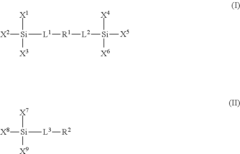
- the plurality of polar moieties are polymer units derived from one or more polar compounds of formulae I or II:
- L 1 , L 2 and L 3 are linker groups, such as, for example C 1 to C 6 alkyl bridge groups;
- X 1 , X 2 , X 3 , X 4 , X 5 , X 6 , X 7 , X 8 and X 9 are independently selected from the group consisting of a hydroxyl, a reactive alkoxide functionality and an unreactive aliphatic functionality;
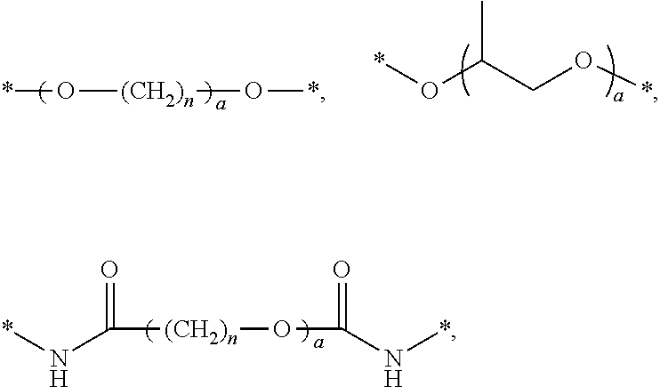
- R 1 and R 2 are independently selected from the group consisting of: a) a substituted or unsubstituted polyether group optionally comprising one or more amide moieties, carbonyl moieties, carboxylic acid ester moieties or amine moieties and b) a polyamine group optionally comprising a saturated hydrocarbon chain moiety.
- R 1 moieties examples include the following:
- n is an integer ranging from 0 to 50.
- R 2 moieties examples include the following:
- a is an integer ranging from 0 to about 30; and m and n are integers ranging from 0 to 50.
- the polar groups of the present disclosure are generally considered to be hydrophilic.
- the degree or extent of wetting and release of the topcoat is controlled by the amounts of the hydrophobic and hydrophilic precursors incorporated into the formulation.
- polar functional groups When more hydrophilic, polar functional groups are incorporated into the coating the surface free energy of the polydiphenylsiloxane-based material increases. Yet these coatings can still remain resistant to contamination (for example by aqueous latex-based pigmented inks) while providing suitable surface free energy for wettability purposes.
- any concentration of polar moieties can be employed in the polymer network to provide the desired surface energy.
- the polar moieties can be included in the polymer network in an amount ranging from about 5% to about 90% by weight relative to the total weight of the polymer network, such as about 10% to about 70%, or about 20% to about 50% by weight relative to the total weight of the polymer network.
- Multiple types of polar moieties can be employed.
- the siloxane polymer network composition can comprise at least one polar moiety formed from a compound of formula I and at least one polar moiety formed from a compound of formula II.
- the siloxane polymer network can also include a plurality of non-polar moieties formed by combining one or more non-polar compounds with the coating composition.
- An example of a siloxane polymer network that includes both polar and non-polar moieties is shown in FIG. 2 .
- the non-polar compounds include one or more siloxane compounds of formulae I or II, where L 1 , L 2 , L 3 , X 1 , X 2 , X 3 , X 4 , X 5 , X 6 , X 7 , X 8 and X 9 are defined as above for the polar groups; and where R 1 and R 2 are independently selected from the group consisting of: a) a linear, branched or cyclic, saturated or unsaturated alkyl group, b) a perfluorinated linear, branched or cyclic carbon chain and c) a group having one or more dialkylsiloxane units.
- R 1 can be selected from the group consisting of:
- R 2 moieties include those selected from the group consisting of:
- x is an integer ranging from 0 to 30 and n is an integer ranging from 0 to 50.
- the polymer network can be made up of at least 10% silicon by weight.
- the polymer network can include about 20% to about 70% by weight silicon, such as about 30% to about 60% by weight silicon, relative to the weight of all atomic components in the cured layer.
- the topcoat layer 140 can have any desired thickness.
- the topcoat layer 140 may have a depth or thickness 142 ranging from about 5 ⁇ m to about 100 ⁇ m, about 10 ⁇ m to about 75 ⁇ m, or about 25 ⁇ m to about 50 ⁇ m.
- the topcoat layer 140 may also include one or more infrared absorptive filler materials 160 such as carbon black, graphene, carbon nanotubes, iron oxide, or a combination thereof.
- the infrared absorptive filler materials may be present in the topcoat layer 140 in an amount ranging from about 0.1 wt % to about 20 wt %, about 1 wt % to about 15 wt %, or about 2 wt % to about 10 wt %, relative to the total weight of the topcoat layer.
- the topcoat layer 140 may further include one or more infrared reflective pigments 150 .
- the conformance layer 120 , the adhesive layer 130 , the topcoat layer 140 , or a combination thereof may include the reflective pigments 150 .
- the reflective pigments 150 in the topcoat layer 130 may be the same as the reflective pigments 150 in the conformance layer 120 and/or the adhesive layer 130 , or they may be different.
- the reflective pigments 150 in the topcoat layer 140 may be or include titanium dioxide, nickel rutile, chromium rutile, cobalt-based spinel, chromium oxide, chrome iron nickel black spinel, or a combination thereof.
- the reflective pigments 150 may be present in the topcoat layer 140 in an amount ranging from about 0.1 wt % to about 20 wt %, about 1 wt % to about 15 wt %, or about 2 wt % to about 10 wt %.
- the incorporation of the reflective pigments 150 into the topcoat layer 140 may improve the reflection of radiant energy back into the ink for absorption by the ink components for improved and/or enhanced ink drying.
- the reflective pigments 150 are combined in the topcoat layer 140 with the absorptive materials 160 , such as carbon black, the efficiency of photothermal conversion may be enhanced relative to carbon black alone. Further, the differential rate of drying among different ink colors may be reduced or eliminated. The amount of radiant energy waste may be reduced, and the efficiency of the ink drying may improve.
- the topcoat layer 140 of the present disclosure can be made by any suitable polymerization process.
- the silanol terminated dialkoxysiloxane-diphenylsiloxane monomers, polar monomers and optional non-polar monomers may be combined and cross-linked via condensation chemistry under neutral pH. Hydrolysis and condensation of alkoxide or hydroxide groups can occur, and upon curing at elevated temperatures produces a cross-linked polydiphenylsiloxane coating with polar and optional non-polar moieties that may be used as a surface layer for a transfix surface member in an aqueous ink jet transfix machine.
- the cross-linked polydiphenylsiloxane-based coating prepared according to the instant disclosure can withstand high temperature conditions without melting or degradation, is mechanically robust under such conditions and/or provides good wettability.
- a titanium catalyst can be employed to promote reaction and cross-linking of the monomers to form the polymer network of topcoat layer 140 . This can result in the transfix surface member comprising titanium in an amount ranging from about 0.01% to about 5% by weight relative to the total weight of the polymer network.
- the catalyst can be selected from the group consisting of titanate catalysts, zirconate catalysts and tin catalysts, for example titanium(IV) ethoxide (tetraethyl orthotitanate), titanium(IV) isopropoxide (tetraisopropyl orthotitanate), titanium(IV) butoxide (TYZOR® TBT), titanium diisopropoxide bis(acetylacetanoate) (TYZOR® AA), titanium(IV) (triethanolaminato) isopropoxide (TYZOR® TE), titanium(IV) 2-ethylhexoxide (TYZOR® TOT), titanium di-n-butoxide(bis-2,4-pentanedionate), titanium diisopropoxide(bis-2,4-pentanedionate), titanium trimethylsiloxide, zirconium(IV)bis(diethylcitrato)dipropoxide (TYZOR® ZEC), bis(2-ethyl
- Solvents used for processing of precursors and coating of layers include organic hydrocarbon solvents; alcohols, such as methanol, ethanol, isopropanol and n-butanol; and fluorinated solvents. Further examples of solvents include ketones such as methyl ethyl ketone, methyl isobutyl ketone, and cyclohexanone. Mixtures of solvents may be used.
- the solvent may be an alcohol solvent.
- the alcohol solvent may be present in an amount of at least 1 weight percent of the formulation composition, such as from about 1 weight percent to about 60 weight percent, such as from about 3 weight percent to about 40 weight percent, or from about 5 weight percent to about 20 weight percent of the formulation composition.
- the liquid coating compositions formed can include any suitable amount of coating precursors and solvent.
- solids loading of the composition can range from about 20 weight percent to about 80 weight percent, such as from about 30 weight percent to about 70 weight percent, or from about 40 weight percent to about 60 weight percent.
- the liquid coating formulation may be applied to a substrate.
- the coating solution may be deposited on a substrate using any suitable liquid deposition technique.
- Exemplary methods for depositing the coating solution on the substrate include draw-down coating, spray coating, spin coating, flow coating, dipping, spraying such as by multiple spray applications of very fine thin films, casting, web-coating, roll-coating, extrusion molding, laminating, or the like.
- the thickness of the coating solution may be from about 100 nm to about 200 ⁇ m, such as from about 500 nm to about 100 ⁇ m, or from about 1 ⁇ m to about 50 ⁇ m.
- a cured film may be formed upon standing or from drying with heat treatment, forming a fully networked polydiphenylsiloxane coating on the substrate.
- the curing processes according to the instant disclosure may be carried out at any suitable temperature, such as from about 25° C. to about 200° C., or from about 40° C. to about 150° C., or from about 65° C. to about 100° C.
- the curing process can occur for any suitable length of time.
- the monomers are networked together so that all or substantially all polar and optional non-polar monomers are bonded together with the diphenylsiloxane moieties in the cured coating via silicon oxide (Si—O—Si) linkages. Therefore, a molecular weight is not given for the polydiphenylsiloxane-based networked polymer because the coating is cross-linked into one system.
- the networked polydiphenylsiloxane composition does not dissolve when exposed to solvents (such as ketones, chlorinated solvents, ethers etc.).
- the polymer network can be thermally stable at temperatures up to 300° C. or more, depending on the system. As shown in FIG. 3 , the mass loss of the networked polydiphenylsiloxane at about 300° C. is about 1.2 percent by weight. The thermal stability allows a wider operating window for the ink jet transfix apparatus. Furthermore, the cross-linking density is adjustable based on monomer choice, which enables tuning of their mechanical properties.
- the networked polydiphenylsiloxane coatings can have moderate surface free energy, which can be tuned based on the type and amount of polar and non-polar moieties.
- Example ranges of potential surface free energies for the coatings include ranges of about 20 mN/m to about 40 mN/m, or about 23 mN/m to about 37 mN/m, or about 25 mN/m to about 35 mN/m.
- FIG. 4 depicts a printer 200 including the transfix surface member 100 , according to an embodiment of the present disclosure.
- the printer 200 may be an indirect aqueous inkjet printer that forms an ink image on a surface of the transfix surface member 100 .
- Examples of aqueous inkjet printers are described in more detail in U.S. patent application Ser. No. 14/032,945, filed Sep. 20, 2013, and U.S. patent application Ser. No. 14/105,498, filed Dec. 13, 2013, the disclosures of both of which are herein incorporated by reference in their entireties.
- the printer 200 includes a frame 211 that supports operating subsystems and components, which are described below.
- the printer 200 includes an intermediate transfer member, which is illustrated as comprising a rotating imaging drum 212 and a transfix surface member 100 .
- the transfix surface member 100 is in the form of a blanket that is manufactured separately and then mounted about the circumference of the drum 212 .
- the transfix surface member 100 is coated directly onto the intermediate transfer member so as to form an integral outer surface thereof.
- the substrate 110 of the transfer member may be a surface of the drum 212 .
- the intermediate transfer member may be in the form of an endless belt comprising the transfix surface member coated thereon. Suitable endless belt mechanisms are well known in the art.
- the transfix surface member 100 may move in a direction 216 as the drum 212 rotates.
- the transfix roller 219 may rotate in the direction 217 and be loaded against the surface of transfix surface member 100 to form the transfix nip 218 , within which ink images formed on the surface of transfix surface member 100 are transfixed onto a print medium 249 .
- a heater (not shown) in the drum 212 or in another location of the printer heats the transfix surface member 100 to a temperature in a range of, for example, approximately 50° C. to approximately 70° C. The elevated temperature promotes partial drying of the liquid carrier that is used to deposit the hydrophilic composition and the water in the aqueous ink drops that are deposited on the transfix surface member 100 .
- a surface maintenance unit (“SMU”) 292 may remove residual ink left on the surface of the transfix surface member 100 after the ink images are transferred to the print medium 249 .
- the SMU 292 may include a coating applicator, such as a donor roller (not shown), which is partially submerged in a reservoir (not shown) that holds a hydrophilic sacrificial coating composition in a liquid carrier.
- the donor roller may draw the liquid sacrificial coating composition from the reservoir and deposit a layer of the sacrificial composition on the transfix surface member 100 .
- the dried sacrificial coating may substantially cover a surface of the transfix surface member 100 before the printer 200 ejects ink drops during a print process.
- the printer 200 may also include an aqueous ink supply and delivery subsystem 220 that has at least one source 222 of one color of aqueous ink.
- the printer 200 is a multicolor image producing machine, the ink delivery system 220 including, for example, four (4) sources 222 , 224 , 226 , 228 , representing four (4) different colors CYMK (cyan, yellow, magenta, black) of aqueous inks.
- CYMK cyan, yellow, magenta, black
- a printhead system 230 may include a printhead support 232 , which provides support for a plurality of printhead modules, also known as print box units, 234 A- 234 D. Each printhead module 234 A- 234 D effectively extends across a width of the transfix surface member 100 and ejects ink drops onto the transfix surface member 100 .
- a printhead module 234 A- 234 D may include a single printhead or a plurality of printheads configured in a staggered arrangement.
- the printhead modules 234 A- 234 D may include associated electronics, ink reservoirs, and ink conduits to supply ink to the one or more printheads, as would be understood by one of ordinary skill in the art.
- the image dryer 204 may include a heater 205 , such as a radiant infrared heater, a radiant near infrared heater, and/or a forced hot air convection heater.
- the image dryer 204 may also include a dryer 206 , which is illustrated as a heated air source, and air returns 207 A and 207 B.
- the heater 205 may apply, for example, infrared heat to the printed image on the surface of the transfix surface member 100 to evaporate water or solvent in the ink.
- the heated air source 206 may direct heated air over the ink to supplement the evaporation of the water or solvent from the ink.
- the dryer 206 may be a heated air source with the same design as the dryer 296 . While the dryer 296 may be positioned along the process direction to dry the hydrophilic sacrificial coating, the dryer 206 may also be positioned along the process direction after the printhead modules 234 A- 234 D to at least partially dry the aqueous ink on the transfix surface member 100 . The air may then be collected and evacuated by air returns 207 A and 207 B to reduce the interference of the air flow with other components in the printing area.
- the printer 200 may further include a print medium supply and handling system 240 that stores, for example, one or more stacks of paper print mediums of various sizes, as well as various other components useful for handling and transferring the print medium. While example handling and transfer components are illustrated at 242 , 244 , 246 , 250 and 264 , any suitable supply and handling system can be employed, as would be readily understood by one of ordinary skill in the art. Operation and control of the various subsystems, components, and functions of the printer 200 may be performed with the aid of the controller 280 . In an embodiment, the controller 280 may be the main multi-tasking processor for operating and controlling all of the other machine subsystems and functions.
- components within the printer 200 may operate to perform a process for transferring and fixing the image or images from the transfix surface member 100 to media.
- heat and/or pressure can be applied by the transfix roller 219 to the back side of the heated print medium 249 to facilitate the transfixing (transfer and fusing) of the image from the intermediate transfer member onto the print medium 249 .
- the sacrificial coating is also transferred from the intermediate transfer member to the print medium 249 as part of the transfixing process.
- the image receiving surface passes a cleaning unit that can remove any residual portions of the sacrificial coating and small amounts of residual ink from the image receiving surface of the transfix surface member 100 .
- the word “printer” encompasses any apparatus that performs a print outputting function for any purpose, such as a digital copier, bookmaking machine, facsimile machine, a multi-function machine, electrostatographic device, etc.
- DPS-based materials of Examples 1-3 were formulated and coated on a variety of different substrates. In all cases the coatings exhibited strong adhesion to the substrates enabling primer-free application. Following preparation ATR-IR spectra were recorded. Minimal —OH stretching was observed and is consistent with complete or near complete condensation of all silanol functional groups (complete reaction). TGA spectra were collected to evaluate thermal stability ( FIG. 3 ). All coatings were stable to 300° C. Differences in ink wettability were observed by airbrushing atomized ink droplets onto the surface and looking at the droplet behavior by optical microscopy.
- Siloxane formulation components for Example 1 are set forth in Table 1 below.
- Silanol terminated dimethylsiloxane-diphenylsiloxane copolymer (1.52 g), triethoxysilylethyl terminated polydimethylsiloxane (0.57 g), N,N′-bis-[(3-triethoxysilylpropyl)aminocarbonyl]polyethylene oxide (10-15 EO) (0.37 g), and 3-(trimethoxysilylpropyl)diethylenetriamine (0.57 g) were combined in a vial and mixed by vortex for 10 s at 2500 rpm.
- Cyclohexanone (0.27 g) was added to the vial, followed by titanium acetylacetonate (0.20 g of a 75% active solution in IPA; 5 wt % active catalyst relative to all siloxanes). The solution was mixed by vortex for 10 s at 2500 rpm.
- the coating solution was filtered through a 0.45 ⁇ m PTFE filter immediately prior to coating to remove any particulates.
- the coating solution was draw down coated on polyimide or aluminum or silicone or Mylar substrates or cast onto quartz yielding uniform coatings.
- the coating solution formed a stable wet layer on all substrates tested.
- the coatings were cured at 90° C. with ⁇ 50% relative humidity for 1 h to give clear, uniform films.
- Siloxane formulation components for Example 2 are set forth in Table 2 below.
- silane terminated dimethylsiloxane-diphenylsiloxane copolymer (1.12 g), N,N′-bis-[(3-triethoxysilylpropyl)aminocarbonyl]polyethylene oxide (10-15 EO) (0.37 g), and 3-(trimethoxysilylpropyl)diethylenetriamine (0.60 g) were combined in a vial and mixed by vortex for 10 s at 2500 rpm.
- Cyclohexanone (0.33 g) was added to the vial, followed by titanium acetylacetonate (0.14 g of a 75% active solution in IPA; 5 wt % active catalyst relative to all silanes). The solution was mixed by vortex for 10 s at 2500 rpm.
- the coating solution was filtered through a 0.45 ⁇ m PTFE filter immediately prior to coating to remove any particulates.
- the coating solution was draw down coated on polyimide or aluminum or silicone or Mylar substrates or cast onto quartz yielding uniform coatings.
- the coating solution formed a stable wet layer on all substrates tested.
- the coatings were cured at 90° C. with ⁇ 50% relative humidity for 1 h to give clear, uniform films.
- Siloxane formulation components for Example 3 are set forth in Table 3 below.
- silane terminated dimethylsiloxane-diphenylsiloxane copolymer (1.51 g), triethoxysilylethyl terminated polydimethylsiloxane (0.57 g), 2-(acetoxy(polyethyleneoxy)propyl)triethoxysilane (0.37 g), and 3-(trimethoxysilylpropyl)diethylenetriamine (0.60 g) were combined in a vial and mixed by vortex for 10 s at 2500 rpm. Cyclohexanone (0.26 g) was added to the vial, followed by titanium acetylacetonate (0.21 g of a 75% active solution in IPA; 5 wt % active catalyst relative to all silanes).
- the solution was mixed by vortex for 10 s at 2500 rpm.
- the coating solution was filtered through a 0.45 ⁇ m PTFE filter immediately prior to coating to remove any particulates.
- the coating solution was draw down coated on polyimide or aluminum or silicone or Mylar substrates or cast onto quartz yielding uniform coatings.
- the coating solution formed a stable wet layer on all substrates tested.
- the coatings were cured at 90° C. with ⁇ 50% relative humidity for 1 h to give clear, uniform films.
- Siloxane formulation components for Example 4 are set forth in Table 4 below.
- silanes were combined in a vial and mixed by vortex for 10 s at 2500 rpm. Cyclohexanone (0.26 g) was added to the vial, followed by titanium acetylacetonate (0.46 g of a 75% active solution in IPA; 5 wt % active catalyst relative to all silanes).
- the solution was mixed by vortex for 10 s at 2500 rpm.
- the coating solution was filtered through a 0.45 ⁇ m PTFE filter immediately prior to coating to remove any particulates.
- the coating solution was draw down coated on polyimide or aluminum or silicone or Mylar substrates or cast onto quartz yielding uniform coatings.
- the coating solution formed a stable wet layer on all substrates tested.
- the coatings were cured at 130° C. with ⁇ 50% relative humidity for 1 h to give clear, uniform films.
- Siloxane formulation components for Example 5 are set forth in Table 5 below.
- silane terminated dimethylsiloxane-diphenylsiloxane copolymer (1.50 g), triethoxysilylethyl terminated polydimethylsiloxane (1.13 g), and a polar group forming monomer, bis(3-triethoxysilylpropyl)polyethylene oxide (0.39 g), were combined in a vial and mixed by vortex for 10 s at 2500 rpm. Cyclohexanone (0.31 g) was added to the vial, followed by titanium acetylacetonate (0.21 g of a 75% active solution in IPA; 5 wt % active catalyst relative to all silanes).
- the solution was mixed by vortex for 10 s at 2500 rpm.
- the coating solution was filtered through a 0.45 ⁇ m PTFE filter immediately prior to coating to remove any particulates.
- the coating solution was draw down coated on polyimide or aluminum or silicone or Mylar substrates or cast onto quartz yielding uniform coatings.
- the coating solution formed a stable wet layer on all substrates tested.
- the coatings were cured at 90° C. with ⁇ 50% relative humidity for 1 h to give clear, uniform films.
- Siloxane formulation components for Example 6 are set forth in Table 6 below.
- Silanol terminated dimethylsiloxane-diphenylsiloxane copolymer (0.80 g), triethoxysilylethyl terminated polydimethylsiloxane (0.30 g), and two polar group forming monomers, N,N′-bis-[(3-triethoxysilylpropyl)aminocarbonyl]polyethylene oxide (0.30 g) and 3-(trimethoxysilylpropyl)diethylenetriamine (0.66 g), were combined in a vial and mixed by vortex for 10 s at 2500 rpm. Cyclohexanone (0.19 g) was added to the vial, followed by titanium acetylacetonate (0.14 g of a 75% active solution in IPA; 5 wt % active catalyst relative to all silanes).
- the solution was mixed by vortex for 10 s at 2500 rpm.
- the coating solution was filtered through a 0.45 ⁇ m PTFE filter immediately prior to coating to remove any particulates.
- the coating solution was draw down coated on polyimide or aluminum or silicone or Mylar substrates or cast onto quartz yielding uniform coatings.
- the coating solution formed a stable wet layer on all substrates tested.
- the coatings were cured at 90° C. with ⁇ 50% relative humidity for 1 h to give clear, uniform films.
- FIG. 5 shows optical microscopy of atomized ink droplets airbrushed onto the polydiphenylsiloxane-based coatings of Examples 4, 5 and 6, with Example 4 being least polar (left most image) and Example 6 being the most polar (best ink wetting, right-most image).
- FIG. 5 shows that the polydiphenylsiloxane coatings of Examples 5 and 6, containing polar functional groups, exhibited improved wetting of the atomized ink droplets compared to the coating of Example 4, made without polar functional groups.
- compositions of the present disclosure include a class of tunable diphenylsiloxane-based composite materials containing polar functional groups covalently bound in the network.
- these materials exhibit good thermal stability to ⁇ 300° C., adjustable cross-linking density (mechanical) and/or good adhesion to a variety of substrates. These combined properties make this class of materials promising candidates for use as topcoat layers in aqueous transfix printing applications.
Landscapes
- Ink Jet (AREA)
- Ink Jet Recording Methods And Recording Media Thereof (AREA)
Abstract
Description

where R3 is a linear, branched or cyclic, saturated or unsaturated alkyl group containing from about 1 to 30 carbon atoms; s is an integer of from 1 to 500; and t is an integer of from 1 to 300. In an embodiment, the diphenylsiloxane moiety is in an amount ranging from about 10% to about 70% by weight relative to the total weight of the polymer network, such as about 20% to about 50%, or about 30% to about 40% by weight relative to the total weight of the polymer network.

Where L1, L2 and L3 are linker groups, such as, for example C1 to C6 alkyl bridge groups; X1, X2, X3, X4, X5, X6, X7, X8 and X9 are independently selected from the group consisting of a hydroxyl, a reactive alkoxide functionality and an unreactive aliphatic functionality; and R1 and R2 are independently selected from the group consisting of: a) a substituted or unsubstituted polyether group optionally comprising one or more amide moieties, carbonyl moieties, carboxylic acid ester moieties or amine moieties and b) a polyamine group optionally comprising a saturated hydrocarbon chain moiety.

where a is an integer ranging from 0 to about 30; and n is an integer ranging from 0 to 50.

where a is an integer ranging from 0 to about 30; and m and n are integers ranging from 0 to 50.

where a and x are integers ranging from 0 to 30; and n is an integer ranging from 0 to 50. Examples of R2 moieties include those selected from the group consisting of:

where x is an integer ranging from 0 to 30 and n is an integer ranging from 0 to 50.
| TABLE 1 | |||
| wt % | |||
| (of | |||
| Mass | total | ||
| Chemical structure | Chemical name | (g) | silanes) |
 |
Silanol terminated dimethylsiloxane- diphenylsiloxane copolymer | 1.52 | 50 |
 |
Triethoxysilylethyl terminated polydimethylsiloxane | 0.57 | 19 |
 |
N,N′-bis-[(3- triethoxysilylpropyl)aminocarbonyl] polyethylene oxide | 0.37 | 12 |
 |
3-(trimethoxysilylpropyl) diethylenetriamine | 0.57 | 19 |
| TABLE 2 | |||
| wt % | |||
| (of | |||
| Mass | total | ||
| Chemical structure | Chemical name | (g) | silanes) |
 |
Silanol terminated dimethylsiloxane- diphenylsiloxane copolymer | 1.12 | 53 |
 |
N,N′-bis-[(3- triethoxysilylpropyl)aminocarbonyl] polyethylene oxide | 0.37 | 18 |
 |
3-(trimethoxysilylpropyl) diethylenetriamine | 0.60 | 29 |
| TABLE 3 | |||
| wt % | |||
| Mass | (of total | ||
| Chemical structure | Chemical name | (g) | silanes) |
 |
Silanol terminated dimethylsiloxane- diphenylsiloxane copolymer | 1.51 | 50 |
 |
Triethoxysilylethyl terminated polydimethylsiloxane | 0.57 | 19 |
 |
2-(acetoxy(polyethyleneoxy)propyl) triethoxysilane | 0.37 | 12 |
 |
3-(trimethoxysilylpropyl) diethylenetriamine | 0.56 | 19 |
| TABLE 4 | |||
| wt % | |||
| Mass | (of total | ||
| Chemical structure | Chemical name | (g) | silanes) |
 |
Silanol terminated dimethylsiloxane- diphenylsiloxane copolymer | 3.26 | 50 |
 |
Triethoxysilylethyl terminated polydimethylsiloxane | 3.26 | 50 |
| TABLE 5 | |||
| wt % | |||
| Mass | (of total | ||
| Chemical structure | Chemical name | (g) | silanes) |
 |
Silanol terminated dimethylsiloxane- diphenylsiloxane copolymer | 1.50 | 50 |
 |
Triethoxysilylethyl terminated polydimethylsiloxane | 1.13 | 37 |
 |
Bis(3-triethoxysilylpropyl)polyethylene oxide | 0.39 | 13 |
| TABLE 6 | |||
| wt % | |||
| Mass | (of total | ||
| Chemical structure | Chemical name | (g) | silanes) |
 |
Silanol terminated dimethylsiloxane- diphenylsiloxane copolymer | 0.80 | 38 |
 |
Triethoxysilylethyl terminated polydimethylsiloxane | 0.30 | 15 |
 |
N,N′-bis-[(3- triethoxysilylpropyl)aminocarbonyl] polyethylene oxide | 0.30 | 15 |
 |
3-(trimethoxysilylpropyl) diethylenetriamine | 0.66 | 32 |
Claims (20)


—(CF2)n— and
—(CH2)n—, or
*—(CH2)nCH3, and
—(CF2)nCF3

Priority Applications (1)
| Application Number | Priority Date | Filing Date | Title |
|---|---|---|---|
| US14/219,481 US9211697B2 (en) | 2014-03-19 | 2014-03-19 | Transfix surface member coating |
Applications Claiming Priority (1)
| Application Number | Priority Date | Filing Date | Title |
|---|---|---|---|
| US14/219,481 US9211697B2 (en) | 2014-03-19 | 2014-03-19 | Transfix surface member coating |
Publications (2)
| Publication Number | Publication Date |
|---|---|
| US20150266290A1 US20150266290A1 (en) | 2015-09-24 |
| US9211697B2 true US9211697B2 (en) | 2015-12-15 |
Family
ID=54141279
Family Applications (1)
| Application Number | Title | Priority Date | Filing Date |
|---|---|---|---|
| US14/219,481 Expired - Fee Related US9211697B2 (en) | 2014-03-19 | 2014-03-19 | Transfix surface member coating |
Country Status (1)
| Country | Link |
|---|---|
| US (1) | US9211697B2 (en) |
Cited By (15)
| Publication number | Priority date | Publication date | Assignee | Title |
|---|---|---|---|---|
| US9421758B2 (en) | 2014-09-30 | 2016-08-23 | Xerox Corporation | Compositions and use of compositions in printing processes |
| US9428663B2 (en) | 2014-05-28 | 2016-08-30 | Xerox Corporation | Indirect printing apparatus employing sacrificial coating on intermediate transfer member |
| US9494884B2 (en) | 2014-03-28 | 2016-11-15 | Xerox Corporation | Imaging plate coating composite composed of fluoroelastomer and aminosilane crosslinkers |
| US9550908B2 (en) | 2014-09-23 | 2017-01-24 | Xerox Corporation | Sacrificial coating for intermediate transfer member of an indirect printing apparatus |
| US9593255B2 (en) | 2014-09-23 | 2017-03-14 | Xerox Corporation | Sacrificial coating for intermediate transfer member of an indirect printing apparatus |
| US9611404B2 (en) | 2014-09-23 | 2017-04-04 | Xerox Corporation | Method of making sacrificial coating for an intermediate transfer member of indirect printing apparatus |
| US9683130B2 (en) | 2014-03-19 | 2017-06-20 | Xerox Corporation | Polydiphenylsiloxane coating formulation and method for forming a coating |
| US9718964B2 (en) | 2015-08-19 | 2017-08-01 | Xerox Corporation | Sacrificial coating and indirect printing apparatus employing sacrificial coating on intermediate transfer member |
| US9752042B2 (en) | 2015-02-12 | 2017-09-05 | Xerox Corporation | Sacrificial coating compositions comprising polyvinyl alcohol and waxy starch |
| US9816000B2 (en) | 2015-03-23 | 2017-11-14 | Xerox Corporation | Sacrificial coating and indirect printing apparatus employing sacrificial coating on intermediate transfer member |
| US9956760B2 (en) | 2014-12-19 | 2018-05-01 | Xerox Corporation | Multilayer imaging blanket coating |
| US11478991B2 (en) | 2020-06-17 | 2022-10-25 | Xerox Corporation | System and method for determining a temperature of an object |
| US11499873B2 (en) | 2020-06-17 | 2022-11-15 | Xerox Corporation | System and method for determining a temperature differential between portions of an object printed by a 3D printer |
| US11498354B2 (en) | 2020-08-26 | 2022-11-15 | Xerox Corporation | Multi-layer imaging blanket |
| US11767447B2 (en) | 2021-01-19 | 2023-09-26 | Xerox Corporation | Topcoat composition of imaging blanket with improved properties |
Families Citing this family (2)
| Publication number | Priority date | Publication date | Assignee | Title |
|---|---|---|---|---|
| WO2017151634A1 (en) * | 2016-02-29 | 2017-09-08 | The Regents Of The University Of California | Fluorescent and/or nir coatings for medical objects, object recovery systems and methods |
| US20220119657A1 (en) * | 2020-10-20 | 2022-04-21 | Lawrence Livermore National Security, Llc | Transparent 3d printed siloxane elastomers |
Citations (5)
| Publication number | Priority date | Publication date | Assignee | Title |
|---|---|---|---|---|
| US4970098A (en) * | 1990-04-18 | 1990-11-13 | International Business Machines Corporation | Coatings for hot roll fusers |
| US5464703A (en) * | 1994-06-29 | 1995-11-07 | Eastman Kodak Company | Tin oxide filled dimethylsiloxane-fluoroalkylsiloxane fuser roll for fixing toner to a substrate |
| US5474852A (en) * | 1994-06-29 | 1995-12-12 | Eastman Kodak Company | Tin oxide filled diphenylsiloxane-dimethylsiloxane fuser member for fixing toner to a substrate |
| US5547759A (en) * | 1993-12-09 | 1996-08-20 | Eastman Kodak Company | Coated fuser members and methods of making coated fuser members |
| US6586100B1 (en) * | 1998-12-16 | 2003-07-01 | Nexpress Solutions Llc | Fluorocarbon-silicone interpenetrating network useful as fuser member coating |
-
2014
- 2014-03-19 US US14/219,481 patent/US9211697B2/en not_active Expired - Fee Related
Patent Citations (5)
| Publication number | Priority date | Publication date | Assignee | Title |
|---|---|---|---|---|
| US4970098A (en) * | 1990-04-18 | 1990-11-13 | International Business Machines Corporation | Coatings for hot roll fusers |
| US5547759A (en) * | 1993-12-09 | 1996-08-20 | Eastman Kodak Company | Coated fuser members and methods of making coated fuser members |
| US5464703A (en) * | 1994-06-29 | 1995-11-07 | Eastman Kodak Company | Tin oxide filled dimethylsiloxane-fluoroalkylsiloxane fuser roll for fixing toner to a substrate |
| US5474852A (en) * | 1994-06-29 | 1995-12-12 | Eastman Kodak Company | Tin oxide filled diphenylsiloxane-dimethylsiloxane fuser member for fixing toner to a substrate |
| US6586100B1 (en) * | 1998-12-16 | 2003-07-01 | Nexpress Solutions Llc | Fluorocarbon-silicone interpenetrating network useful as fuser member coating |
Non-Patent Citations (2)
| Title |
|---|
| Brynn Dooley et al., "Aqueous Ink Jet Blanket", U.S. Appl. No. 14/203,667, filed Mar. 11, 2014. |
| Brynn Dooley, "Polydiphenylsiloxane Coating Formulation and Method for Forming a Coating", U.S. Patent Application No. (to be assigned), filed Mar. 19, 2014. |
Cited By (21)
| Publication number | Priority date | Publication date | Assignee | Title |
|---|---|---|---|---|
| US9683130B2 (en) | 2014-03-19 | 2017-06-20 | Xerox Corporation | Polydiphenylsiloxane coating formulation and method for forming a coating |
| US10081739B2 (en) | 2014-03-19 | 2018-09-25 | Xerox Corporation | Polydiphenylsiloxane coating formulation and method for forming a coating |
| US9494884B2 (en) | 2014-03-28 | 2016-11-15 | Xerox Corporation | Imaging plate coating composite composed of fluoroelastomer and aminosilane crosslinkers |
| US9796192B2 (en) | 2014-03-28 | 2017-10-24 | Xerox Corporation | Imaging plate coating composite composed of fluoroelastomer and aminosilane crosslinkers |
| US9790373B2 (en) | 2014-05-28 | 2017-10-17 | Xerox Corporation | Indirect printing apparatus employing sacrificial coating on intermediate transfer member |
| US9428663B2 (en) | 2014-05-28 | 2016-08-30 | Xerox Corporation | Indirect printing apparatus employing sacrificial coating on intermediate transfer member |
| US9926456B2 (en) | 2014-09-23 | 2018-03-27 | Xerox Corporation | Method of making sacrificial coating for an intermediate transfer member of indirect printing apparatus |
| US9593255B2 (en) | 2014-09-23 | 2017-03-14 | Xerox Corporation | Sacrificial coating for intermediate transfer member of an indirect printing apparatus |
| US10336910B2 (en) | 2014-09-23 | 2019-07-02 | Xerox Corporation | Sacrificial coating for intermediate transfer member of an indirect printing apparatus |
| US9783697B2 (en) | 2014-09-23 | 2017-10-10 | Xerox Corporation | Sacrificial coating for intermediate transfer member of an indirect printing apparatus |
| US9611404B2 (en) | 2014-09-23 | 2017-04-04 | Xerox Corporation | Method of making sacrificial coating for an intermediate transfer member of indirect printing apparatus |
| US9550908B2 (en) | 2014-09-23 | 2017-01-24 | Xerox Corporation | Sacrificial coating for intermediate transfer member of an indirect printing apparatus |
| US9421758B2 (en) | 2014-09-30 | 2016-08-23 | Xerox Corporation | Compositions and use of compositions in printing processes |
| US9956760B2 (en) | 2014-12-19 | 2018-05-01 | Xerox Corporation | Multilayer imaging blanket coating |
| US9752042B2 (en) | 2015-02-12 | 2017-09-05 | Xerox Corporation | Sacrificial coating compositions comprising polyvinyl alcohol and waxy starch |
| US9816000B2 (en) | 2015-03-23 | 2017-11-14 | Xerox Corporation | Sacrificial coating and indirect printing apparatus employing sacrificial coating on intermediate transfer member |
| US9718964B2 (en) | 2015-08-19 | 2017-08-01 | Xerox Corporation | Sacrificial coating and indirect printing apparatus employing sacrificial coating on intermediate transfer member |
| US11478991B2 (en) | 2020-06-17 | 2022-10-25 | Xerox Corporation | System and method for determining a temperature of an object |
| US11499873B2 (en) | 2020-06-17 | 2022-11-15 | Xerox Corporation | System and method for determining a temperature differential between portions of an object printed by a 3D printer |
| US11498354B2 (en) | 2020-08-26 | 2022-11-15 | Xerox Corporation | Multi-layer imaging blanket |
| US11767447B2 (en) | 2021-01-19 | 2023-09-26 | Xerox Corporation | Topcoat composition of imaging blanket with improved properties |
Also Published As
| Publication number | Publication date |
|---|---|
| US20150266290A1 (en) | 2015-09-24 |
Similar Documents
| Publication | Publication Date | Title |
|---|---|---|
| US9211697B2 (en) | Transfix surface member coating | |
| JP6472372B2 (en) | Multi-layer imaging bracket coating | |
| US9353290B2 (en) | Transfix surface member coating | |
| US10081739B2 (en) | Polydiphenylsiloxane coating formulation and method for forming a coating | |
| US9259915B2 (en) | Aqueous ink jet blanket | |
| US8692011B2 (en) | Coatings for ink jet print head face | |
| US8851630B2 (en) | Low adhesion sol gel coatings with high thermal stability for easy clean, self cleaning printhead front face applications | |
| JP5818340B2 (en) | Method for forming water repellent film | |
| US9109140B2 (en) | Mixed organosiloxane networks for tunable surface properties for blanket substrates for indirect printing methods | |
| CN102001225B (en) | Liquid ejection head | |
| JP5752816B2 (en) | Water repellent film manufacturing method, nozzle plate, ink jet head, and ink jet recording apparatus | |
| US8841401B1 (en) | Thermally stable oleophobic anti-wetting coating for inkjet printhead face | |
| US9683133B2 (en) | Fluorinated organosiloxane network composition | |
| JP2011194668A (en) | Method for forming water repellent film, nozzle plate and ink jet head equipped with the same, and electronic device | |
| US9493676B2 (en) | Formulation composition for fluorinated organosiloxane network | |
| JP2011073283A (en) | Method for forming organic film, organic film, nozzle plate, inkjet head, and electronic device | |
| JP2006159730A (en) | Wiper blade member for ink jet recording head and ink jet recording method | |
| JP2004174834A (en) | Overcoating liquid, and image recording method and recorded matter using the same | |
| JP2019010756A (en) | Transfer type inkjet recording method, and transfer type inkjet recording device | |
| JP2019018564A (en) | Inkjet recording method and inkjet recording apparatus | |
| JP2013121717A (en) | Image recording method |
Legal Events
| Date | Code | Title | Description |
|---|---|---|---|
| AS | Assignment |
Owner name: XEROX CORPORATION, CONNECTICUT Free format text: ASSIGNMENT OF ASSIGNORS INTEREST;ASSIGNORS:DOOLEY, BRYNN;IFTIME, GABRIEL;SISLER, GORDON;AND OTHERS;REEL/FRAME:032475/0538 Effective date: 20140311 |
|
| FEPP | Fee payment procedure |
Free format text: PAYOR NUMBER ASSIGNED (ORIGINAL EVENT CODE: ASPN); ENTITY STATUS OF PATENT OWNER: LARGE ENTITY |
|
| STCF | Information on status: patent grant |
Free format text: PATENTED CASE |
|
| MAFP | Maintenance fee payment |
Free format text: PAYMENT OF MAINTENANCE FEE, 4TH YEAR, LARGE ENTITY (ORIGINAL EVENT CODE: M1551); ENTITY STATUS OF PATENT OWNER: LARGE ENTITY Year of fee payment: 4 |
|
| AS | Assignment |
Owner name: CITIBANK, N.A., AS AGENT, DELAWARE Free format text: SECURITY INTEREST;ASSIGNOR:XEROX CORPORATION;REEL/FRAME:062740/0214 Effective date: 20221107 |
|
| AS | Assignment |
Owner name: XEROX CORPORATION, CONNECTICUT Free format text: RELEASE OF SECURITY INTEREST IN PATENTS AT R/F 062740/0214;ASSIGNOR:CITIBANK, N.A., AS AGENT;REEL/FRAME:063694/0122 Effective date: 20230517 |
|
| AS | Assignment |
Owner name: CITIBANK, N.A., AS COLLATERAL AGENT, NEW YORK Free format text: SECURITY INTEREST;ASSIGNOR:XEROX CORPORATION;REEL/FRAME:064760/0389 Effective date: 20230621 |
|
| FEPP | Fee payment procedure |
Free format text: MAINTENANCE FEE REMINDER MAILED (ORIGINAL EVENT CODE: REM.); ENTITY STATUS OF PATENT OWNER: LARGE ENTITY |
|
| AS | Assignment |
Owner name: JEFFERIES FINANCE LLC, AS COLLATERAL AGENT, NEW YORK Free format text: SECURITY INTEREST;ASSIGNOR:XEROX CORPORATION;REEL/FRAME:065628/0019 Effective date: 20231117 |
|
| LAPS | Lapse for failure to pay maintenance fees |
Free format text: PATENT EXPIRED FOR FAILURE TO PAY MAINTENANCE FEES (ORIGINAL EVENT CODE: EXP.); ENTITY STATUS OF PATENT OWNER: LARGE ENTITY |
|
| STCH | Information on status: patent discontinuation |
Free format text: PATENT EXPIRED DUE TO NONPAYMENT OF MAINTENANCE FEES UNDER 37 CFR 1.362 |
|
| AS | Assignment |
Owner name: CITIBANK, N.A., AS COLLATERAL AGENT, NEW YORK Free format text: SECURITY INTEREST;ASSIGNOR:XEROX CORPORATION;REEL/FRAME:066741/0001 Effective date: 20240206 |
|
| FP | Lapsed due to failure to pay maintenance fee |
Effective date: 20231215 |