US9173304B2 - Vertical blindmate scaling of identical system boards - Google Patents
Vertical blindmate scaling of identical system boards Download PDFInfo
- Publication number
- US9173304B2 US9173304B2 US13/945,560 US201313945560A US9173304B2 US 9173304 B2 US9173304 B2 US 9173304B2 US 201313945560 A US201313945560 A US 201313945560A US 9173304 B2 US9173304 B2 US 9173304B2
- Authority
- US
- United States
- Prior art keywords
- connector
- printed circuit
- guide bracket
- circuit board
- distal
- Prior art date
- Legal status (The legal status is an assumption and is not a legal conclusion. Google has not performed a legal analysis and makes no representation as to the accuracy of the status listed.)
- Active, expires
Links
Images


Classifications
-
- H—ELECTRICITY
- H05—ELECTRIC TECHNIQUES NOT OTHERWISE PROVIDED FOR
- H05K—PRINTED CIRCUITS; CASINGS OR CONSTRUCTIONAL DETAILS OF ELECTRIC APPARATUS; MANUFACTURE OF ASSEMBLAGES OF ELECTRICAL COMPONENTS
- H05K3/00—Apparatus or processes for manufacturing printed circuits
- H05K3/36—Assembling printed circuits with other printed circuits
- H05K3/368—Assembling printed circuits with other printed circuits parallel to each other
-
- H—ELECTRICITY
- H01—ELECTRIC ELEMENTS
- H01R—ELECTRICALLY-CONDUCTIVE CONNECTIONS; STRUCTURAL ASSOCIATIONS OF A PLURALITY OF MUTUALLY-INSULATED ELECTRICAL CONNECTING ELEMENTS; COUPLING DEVICES; CURRENT COLLECTORS
- H01R12/00—Structural associations of a plurality of mutually-insulated electrical connecting elements, specially adapted for printed circuits, e.g. printed circuit boards [PCB], flat or ribbon cables, or like generally planar structures, e.g. terminal strips, terminal blocks; Coupling devices specially adapted for printed circuits, flat or ribbon cables, or like generally planar structures; Terminals specially adapted for contact with, or insertion into, printed circuits, flat or ribbon cables, or like generally planar structures
- H01R12/70—Coupling devices
- H01R12/7082—Coupling device supported only by cooperation with PCB
-
- H—ELECTRICITY
- H05—ELECTRIC TECHNIQUES NOT OTHERWISE PROVIDED FOR
- H05K—PRINTED CIRCUITS; CASINGS OR CONSTRUCTIONAL DETAILS OF ELECTRIC APPARATUS; MANUFACTURE OF ASSEMBLAGES OF ELECTRICAL COMPONENTS
- H05K2201/00—Indexing scheme relating to printed circuits covered by H05K1/00
- H05K2201/04—Assemblies of printed circuits
- H05K2201/042—Stacked spaced PCBs; Planar parts of folded flexible circuits having mounted components in between or spaced from each other
-
- H—ELECTRICITY
- H05—ELECTRIC TECHNIQUES NOT OTHERWISE PROVIDED FOR
- H05K—PRINTED CIRCUITS; CASINGS OR CONSTRUCTIONAL DETAILS OF ELECTRIC APPARATUS; MANUFACTURE OF ASSEMBLAGES OF ELECTRICAL COMPONENTS
- H05K2201/00—Indexing scheme relating to printed circuits covered by H05K1/00
- H05K2201/10—Details of components or other objects attached to or integrated in a printed circuit board
- H05K2201/10007—Types of components
- H05K2201/10189—Non-printed connector
-
- H—ELECTRICITY
- H05—ELECTRIC TECHNIQUES NOT OTHERWISE PROVIDED FOR
- H05K—PRINTED CIRCUITS; CASINGS OR CONSTRUCTIONAL DETAILS OF ELECTRIC APPARATUS; MANUFACTURE OF ASSEMBLAGES OF ELECTRICAL COMPONENTS
- H05K2201/00—Indexing scheme relating to printed circuits covered by H05K1/00
- H05K2201/10—Details of components or other objects attached to or integrated in a printed circuit board
- H05K2201/10227—Other objects, e.g. metallic pieces
- H05K2201/10325—Sockets, i.e. female type connectors comprising metallic connector elements integrated in, or bonded to a common dielectric support
Definitions
- the present invention relates to interconnections for scaling system boards.
- Processors may be interconnected to achieve greater performance.
- the greater performance may include faster memory access or increased data handling capacity.
- An interconnection between two or more processors may be referred to as a bus, such as with the front side bus (FSB), or a point to point interconnect, such as with the Intel Corporation's QUICKPATH INTERCONNECT (QPI).
- a bus such as with the front side bus (FSB), or a point to point interconnect, such as with the Intel Corporation's QUICKPATH INTERCONNECT (QPI).
- Processor scalability requires a high signal quality electrical connection between the processors.
- electrical connection may be made with conductive traces that extend from the socket for one processor to the socket for another processor.
- the electrical connection must allow for mechanical compliance of each housing. For example, mechanical compliance is required to allow each housing to be properly inserted into a chassis and also to resist damage from shock and vibration.
- One embodiment of the present invention provides an apparatus, comprising a first printed circuit board having a first connector and a hole directly adjacent the first connector, and a second printed circuit board that is parallel to and located below the first printed circuit board, wherein the second printed circuit board has a second connector that is not aligned with the hole through the first printed circuit board.
- the apparatus further comprises a guide bracket secured in the hole and extending orthogonally through the hole, wherein the guide bracket includes first and second slots extending from an upper edge of the guide bracket to a lower edge of the guide bracket on opposing sides of the guide bracket.
- the apparatus comprises a blind plug cable assembly having a housing with a proximal end, a distal end and a tapered central portion between the proximal and distal ends, wherein the proximal end secures a proximal connector for connecting to the first connector on the first printed circuit board, the distal end secures a distal connector for connecting to the second connector on the second printed circuit board, a flexible wired connection extends between the proximal connector and the distal connector, the distal end and distal connector fit through the guide bracket, and the tapered central portion has first and second side pins that engage and pass within the first and second slots of the guide bracket from the upper edge to the lower edge to move the distal connector into alignment with the second connector on the second printed circuit board as the central portion of the assembly moves through the guide bracket toward the second printed circuit board, and the proximal end is sized to engage the guide bracket and assure axial alignment of the assembly and the guide bracket as the proximal connector connects with the first connector and the distal connector connect
- FIG. 1 is a schematic side view of two interconnected system boards.
- FIG. 2 is a perspective view of two system boards connected by a blind plug cable assembly.
- FIG. 3 is a perspective view of a single system board consistent with one embodiment of the present invention.
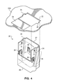
- FIG. 4 is perspective view of a guide bracket aligned for insertion into a hole through the printed circuit board.
- FIG. 5 is perspective view of the upper half of the guide bracket that has been secured to the printed circuit board.
- FIGS. 6A and 6B are perspective and cross-sectional side views, respectively, of a blind plug cable assembly.
- FIGS. 7A-7D are schematic side views showing the process of connecting a blind plug cable assembly between two system boards.
- One embodiment of the present invention provides an apparatus, comprising a first printed circuit board having a first connector and a hole directly adjacent the first connector, and a second printed circuit board that is parallel to and located below the first printed circuit board, wherein the second printed circuit board has a second connector that is not aligned with the hole through the first printed circuit board.
- the apparatus further comprises a guide bracket secured in the hole and extending orthogonally through the hole, wherein the guide bracket includes first and second slots extending from an upper edge of the guide bracket to a lower edge of the guide bracket on opposing sides of the guide bracket.
- the apparatus comprises a blind plug cable assembly having a housing with a proximal end, a distal end and a tapered central portion between the proximal and distal ends, wherein the proximal end secures a proximal connector for connecting to the first connector on the first printed circuit board, the distal end secures a distal connector for connecting to the second connector on the second printed circuit board, a flexible wired connection extends between the proximal connector and the distal connector, the distal end and distal connector fit through the guide bracket, and the tapered central portion has first and second side pins that engage and pass within the first and second slots of the guide bracket from the upper edge to the lower edge to move the distal connector into alignment with the second connector on the second printed circuit board as the central portion of the assembly moves through the guide bracket toward the second printed circuit board, and the proximal end is sized to engage the guide bracket and assure axial alignment of the assembly and the guide bracket as the proximal connector connects with the first connector and the distal connector connect
- the distal connector is secured to a spring loaded member extending from the assembly.
- the spring loaded member preferably has a spring preload force that is equal to or greater than the insertion force required to connect the distal connector to the second connector.
- the spring loaded member may also have a range of distal motion to allow for a range of distances between the first and second printed circuit boards, in which case the flexible wired connection may have sufficient length to extend between the proximal and distal connectors over the range of distances between the first and second printed circuit boards.
- the spring loaded member will preferably allow the distal connector and the second connector to remain connected over a range of variations in the distance between the first and second printed circuit board.
- the distal connector may connect to the second connector before the proximal connector connects to the first connector.
- the first and second slots include an angled portion that angles downward and in the direction of the first socket on the first printed circuit board.
- the slot has an upper end that begins at the upper edge of the guide bracket at a distance from a back wall of the guide bracket that causes the distal connector to be aligned with the guide bracket, and a lower end that ends at the lower edge of the guide bracket at a distance from a front wall of the guide bracket that cause the distal connector to be aligned with the second socket.
- An additional embodiment of the apparatus includes a latch on the opposing sides of the assembly for latching the assembly to the guide bracket with the proximal connector connected to the first connector and the distal connector connected to the second connector.
- the latch may comprise a tab that is outwardly biased to snap into a window in the guide bracket.
- the latch may be retracted and released by pressing a button coupled to the tab in order to overcome the bias and draw the tab inwardly to release the latch.
- the first printed circuit board is secured in a first chassis and the second printed circuit board is secured in a second chassis.
- a hole through a lower wall of the first chassis and a hole through a directly adjacent upper wall of the second chassis are aligned with the bracket through the first printed circuit board, and the hole in the first chassis and the hole in the second chassis are sized to allow the assembly to extend there through without engaging the assembly.
- an alignment feature may be provided for securing the first and second chassis together in alignment, wherein alignment of the first and second chassis aligns the hole through the lower wall of the first chassis with the hole through the directly adjacent upper wall of the second chassis.
- the second connector includes a guide pin for aligning a connector housing of the distal connector with a connector housing of the second connector.
- the connector housing of the second connector may mate with the connector housing of the distal connector for the purpose of aligning a plurality of conductors of the distal connector with a plurality of conductors of the second connector.
- the proximal connector, the distal connector and the wired connections between the proximal and distal connectors establish a quickpath interconnect.
- Other connector types may be similarly implemented. It should also be recognized that any two connectors that intended to be connected together, might be referred to as a socket and a plug. While the first or second connector on the first or second printed circuit board, respectively, may be a socket for connecting with a plug on the assembly, the proximal and distal connectors on the assembly may alternatively include a socket for connecting with a plug on the first or second printed circuit board.
- One embodiment of the guide bracket includes outwardly extending flexible tabs for securing the guide bracket to the first printed circuit board.
- the first printed circuit board has four connectors or socket units and the second printed circuit board has four connectors or socket units.
- two of the connectors may be side-by-side on the first printed circuit board and two of the connectors may be side-by-side on the second printed circuit board.
- Such an apparatus may further include a second hole directly adjacent the side-by-side sockets on the first printed circuit board, wherein the side-by-side sockets on the second printed circuit board are not aligned with the second hole.
- This apparatus may further include a second guide bracket secured in a second hole, wherein the guide bracket includes first and second slots extending from an upper edge of the guide bracket to a lower edge of the guide bracket on opposing sides of the guide bracket.
- a second blind plug cable assembly may have a housing with a proximal end, a distal end and a tapered central portion between the proximal and distal ends, wherein the proximal end secures a pair of proximal connectors for connecting to the two side-by-side sockets on the first printed circuit board, the distal end secures a pair of distal connectors for connecting to the two side-by-side sockets on the second printed circuit board, a first flexible wired connection extends between a proximal connector on a first side of the second assembly and a distal connector on the first side of the second assembly, a second flexible wired connection extends between a proximal connector on a second side of the second assembly and a distal connector on the second side of the second assembly, the distal end and the pair of distal connectors fit through the second guide bracket, and the tapered central portion has first and second side pins that engage and pass within the first and second slots of the second guide bracket from the upper edge to the lower edge to move
- FIG. 1 is a schematic side view of two interconnected system boards.
- a first printed circuit board 20 A is secured in a first chassis 10 A and a second printed circuit board 20 B is secured in a second chassis 10 B.
- the first printed circuit board 20 A has a hole 22 directly adjacent to a first connector 24 and a guide bracket 30 secured in the hole and extending orthogonally to the first printed circuit board 20 A.
- the second printed circuit board 20 B may be identical to the first printed circuit board 20 A for convenience or efficiency, but this is not necessary. However, the second printed circuit board 20 B must have a second connector 23 .
- the first chassis 10 A also has a hole 25 through a lower wall 26 and the second chassis 10 B has a hole 27 through an upper wall 28 , wherein the holes 25 , 27 are generally aligned with the guide bracket 30 of the first printed circuit board 20 A and are sized to allow a blind plug cable assembly 40 to extend there through without engaging the assembly.
- alignment features 29 may be provided for securing the first and second chassis together in alignment, wherein alignment of the first and second chassis 20 A, 20 B aligns the hole 25 through the lower wall 26 of the first chassis with the hole 27 through the directly adjacent upper wall 28 of the second chassis.
- the blind plug cable assembly 40 secured a proximal connector 42 for connecting to the first connector 24 on the first printed circuit board and a distal connector 44 for connecting to the second connector 23 on the second printed circuit board.
- FIG. 2 is a perspective view of two system boards 20 A, 20 B connected by a blind plug cable assembly 40 .
- there are multiple blind plug cable assemblies that are used to convert two standard 4-socket system boards 20 A, 20 B into an 8-socket server using native QPI links.
- the two 4-socket system boards may be installed in a rack within a slide mount server chassis (See FIG. 1 ).
- the system includes two straight links 40 and one cross-link 42 (the double wide central part). Although the double wide link 42 may include two straight links in a common housing, the double wide link 42 is preferably a cross-link that may give the best performance by allowing any two processors to communication with no more than two links (i.e., only one processor therebetween).
- the blind plug cable assemblies 40 , 42 reach the installed position (as shown) by inserting the assemblies downwardly through the guide brackets 30 , 32 , which requires a top cover of the first chassis 10 A (See FIG. 1 ) to be removed. Upon insertion and latching of the assemblies 40 , 42 , the first (upper) chassis' cover would be re-installed and the two chassis could then be slid into an operational position in the rack.
- the assemblies 40 , 42 provide the shortest path possible between two points on the system boards 20 A, 20 B. This is important because system board wire or trace routing/length, connector selection and cable length are major contributors to the noise imparted on the signal.
- the short distance of the assemblies 40 , 42 allows a high data transfer rates without a loss of signal integrity as might occur using blind mate deep plug cabling that comes from the back of the chassis.
- the blind plug cable assemblies 40 , 42 can be easily removed to allow relative motion between the first and second chassis for service of the lower system, such as CPU add/replacement, memory replacement, PCIe boards, and the like.
- FIG. 3 is a perspective view of a single system board 20 A consistent with one embodiment of the present invention.
- the system board may be used in both the upper (first) and lower (second) chassis, but only the upper board 20 A is required to have the holes 22 , 21 .
- the holes 22 , 21 are sized receive a guide bracket (not shown) and positioned on the system board 20 A directly adjacent one a connector 24 .
- the (single-wide) holes 22 are adjacent a single connector 24 and the (double-wide) hole 21 is adjacent two connectors 24 .
- the double-wide hole may differ from the single-wide hole only in width
- a double-wide guide bracket may differ from a single wide guide bracket only in width
- a double-wide blind plug cable assembly may be functionally the same as two of the single-wide blind plug cable assemblies.
- FIG. 4 is perspective view of a guide bracket 30 aligned for insertion into a hole 22 through the printed circuit board 20 A.
- An outline 24 represents the adjacent position of a connector that is not shown in order to focus on the hole 22 and the guide bracket 30 .
- the hole 22 and guide bracket 30 are sized so that the guide bracket is closely received within the hole.
- the two slots 34 may protrude from the opposing sides of the otherwise rectangular profile of the guide bracket 30 , but may also be accommodated by two opposing notches 26 in the hole 22 .
- the guide bracket 30 includes a plurality of flexible outwardly directed latches 36 around the perimeter of the guide bracket that allow the guide bracket to “snap” into place.
- a ramped surface allows the latch 36 to flex inwardly until the edge of the hole in the printed circuit board is received into the central channel of the latch.
- the central channel in the latch 36 should be sized to hold the guide bracket firmly in place, orthogonal to the printed circuit board 20 A, without shifting around within the hole 22 .
- the slots 34 are symmetrical and include an angled portion 35 that angles downward and in the direction of the first connector 24 (leftward in FIG. 4 ) on the first printed circuit board.
- the slot has an upper end that begins at the upper edge of the guide bracket 30 at a distance from a back wall 37 of the guide bracket that causes the distal connector of the assembly (not show) to be aligned with the guide bracket 30 .
- the slot has a lower end that ends at the lower edge of the guide bracket 30 at a distance from a front wall 38 of the guide bracket that causes the distal connector to be aligned with the second socket. This will be shown in greater detail in reference to FIGS. 7A-7D .
- FIG. 5 is perspective view of the upper half of the guide bracket 30 that has been secured to the printed circuit board 20 A.
- the latches 36 have received the printed circuit board 20 A and hold the guide bracket 30 in place.
- the slots 34 pass through the notches 26 . Note that the upper half of the guide bracket 30 is missing the side that is directly adjacent to the first connector 24 .
- FIG. 6A is a perspective view of a blind plug cable assembly 40 .
- the assembly includes a rigid housing 45 that defines a proximal end 46 and a distal end 48 .
- a proximal connector 42 is secured directly to the housing 45 and a distal connector 44 is secured to a sliding member 49 .
- the sliding member 49 is allowed to retract into the housing 45 under a force, as is described in more detail with reference to FIG. 6B .
- the housing 45 has a uniform width (X dimension) along its length (Z dimension) so that the connectors 42 , 44 are always aligned in the X direction as dictated by the position of the hole 22 and the guide bracket 30 (See FIG. 2 ).
- the profile of the housing 45 in the Y dimension is not uniform.
- a front face 47 of the housing 45 secures the connectors 42 , 44 and may be generally straight, although the front face does not need to be flat. Rather, the front is designed to position the connectors 42 , 44 in alignment with the connectors on the system boards.
- a back face (opposite the front face 47 ) of the housing 45 has a proximal portion 50 with a rectangular profile matching the inside profile of the guide bracket (see guide bracket 30 of FIG. 5 ), a middle portion 52 that is angled relative to the proximal portion 50 , and a distal portion 54 that can have any profile that does not prevent the distal connector 44 and distal portion 54 from passing through the guide bracket.
- the housing 45 also supports a pair of guide pins 56 that are symmetrically positioned on opposite sides (X dimension) of the housing for aligning the connectors 42 , 44 with the connectors on the system boards.
- the housing 45 preferably supports a pair of opposing latches 58 that are used to retain the housing 45 of the assembly 40 in an installed position.
- FIG. 6B is a cross-sectional side view of the blind plug cable assembly 40 of FIG. 6A .
- Many of the elements of the assembly 40 discussed in reference to FIG. 6A , are shown in FIG. 6B and labeled with the same reference numbers.
- this view emphasizes the profile of the back surface of the housing 45 , which includes the uniform profile of the proximal portion 50 , the angled profile of the middle portion 52 , and the narrow profile of the distal portion 54 .
- the distal connector 44 is shown secured to the sliding member 49 extending from the distal end 48 of the housing 45 .
- the sliding member 49 is retained in a track 60 that runs parallel to the axis of the distal connector 44 .
- a spring 62 biases the sliding member 49 to the distal end of its movement within the track 60 . Under a sufficient force, the spring 62 may be compressed and allow the sliding member 49 to move in a proximal direction within the track. Preferably, the spring 62 has a spring preload force that is equal to or greater than the insertion force of the distal connector 44 into the connector on the second printed circuit board.
- the proximal connector 42 and the distal connector 44 are electronically connected by a flexible wiring connection 64 that has sufficient slack to accommodate the full range of movement that the sliding member 49 may experience.
- the distal connector 44 Upon insertion of the assembly 40 through the guide bracket, the distal connector 44 will fully seat with the connector on the lower printed circuit board, and then the proximal connector 42 will seat with the connector on the upper printed circuit board to complete the connection between the two boards.
- the latches 58 secured the assembly in the installed position and prevent the proximal connector 42 from being disconnected. Any vertical motion between the two chassis (and the boards) is easily tolerated with no significant motion within the connector interface with the distal connector 44 due to the spring loaded sliding member 44 .
- the connectors 42 , 44 and the flexible wiring connection 64 serve as a scalability cable, which may be a QPI cable.
- FIGS. 7A-7D are schematic side views showing the process of connecting a blind plug cable assembly 40 between two system boards 20 A, 20 B.
- FIG. 7A is a schematic view of the assembly 40 in preparation for the distal connector 44 to be inserted through the guide bracket in the first (upper) system board 20 A.
- FIG. 7B is a schematic view of the assembly 40 with the distal connector and narrow distal end of the assembly inserted through the guide bracket 30 in the system board 20 A and with the pins 56 (one shown) engaged in the upper end of the slots 34 (one shown) in the bracket 30 .
- FIG. 7C is a schematic view of the assembly 40 having advanced further through the guide bracket 30 than in FIG. 7B , such that the pins 56 ride to the distal end of the slot 34 and align the distal connector 44 and the second (lower) connector 23 in the Y direction (front to back).
- FIG. 7D is a schematic view of the assembly 40 after the pin 56 has exited the bottom of the slot 34 in the guide bracket and the wider proximal portion 50 of the assembly is now fully engaged in the guide bracket 30 so that the assembly is maintained in a relatively vertical orientation.
- a guide pin 70 (See FIG. 7C ) on the connector 23 of the lower system board 20 B will engage the distal connector 44 and provide rough alignment of the housings of the connectors 44 , 23 .
- the connector housings themselves will engage and may be responsible for the final fine alignment of the conductive elements in the connectors.
Landscapes
- Engineering & Computer Science (AREA)
- Microelectronics & Electronic Packaging (AREA)
- Manufacturing & Machinery (AREA)
- Coupling Device And Connection With Printed Circuit (AREA)
- Details Of Connecting Devices For Male And Female Coupling (AREA)
Abstract
Description
Claims (19)
Priority Applications (1)
| Application Number | Priority Date | Filing Date | Title |
|---|---|---|---|
| US13/945,560 US9173304B2 (en) | 2013-07-18 | 2013-07-18 | Vertical blindmate scaling of identical system boards |
Applications Claiming Priority (1)
| Application Number | Priority Date | Filing Date | Title |
|---|---|---|---|
| US13/945,560 US9173304B2 (en) | 2013-07-18 | 2013-07-18 | Vertical blindmate scaling of identical system boards |
Publications (2)
| Publication Number | Publication Date |
|---|---|
| US20150022990A1 US20150022990A1 (en) | 2015-01-22 |
| US9173304B2 true US9173304B2 (en) | 2015-10-27 |
Family
ID=52343416
Family Applications (1)
| Application Number | Title | Priority Date | Filing Date |
|---|---|---|---|
| US13/945,560 Active 2034-05-14 US9173304B2 (en) | 2013-07-18 | 2013-07-18 | Vertical blindmate scaling of identical system boards |
Country Status (1)
| Country | Link |
|---|---|
| US (1) | US9173304B2 (en) |
Cited By (3)
| Publication number | Priority date | Publication date | Assignee | Title |
|---|---|---|---|---|
| US20160353573A1 (en) * | 2015-06-01 | 2016-12-01 | Innodisk Corporation | Stack structure of circuit board |
| US20210313720A1 (en) * | 2020-04-06 | 2021-10-07 | Hewlett Packard Enterprise Development Lp | Blind mate connections with different sets of datums |
| TWI805053B (en) * | 2020-11-02 | 2023-06-11 | 美商莫仕有限公司 | Connector holder and connector system for bypass connection applications |
Families Citing this family (2)
| Publication number | Priority date | Publication date | Assignee | Title |
|---|---|---|---|---|
| US11546992B2 (en) * | 2017-08-07 | 2023-01-03 | Sanmina Corporation | Modular motherboard for a computer system and method thereof |
| CN115495407A (en) * | 2021-06-18 | 2022-12-20 | 华为技术有限公司 | Stacked interconnect architecture and electronic device |
Citations (28)
| Publication number | Priority date | Publication date | Assignee | Title |
|---|---|---|---|---|
| US4853830A (en) * | 1988-03-17 | 1989-08-01 | International Business Machines Corporation | Three stage self alignment structure and method |
| JPH04269483A (en) | 1991-02-25 | 1992-09-25 | Fujitsu Ltd | Electronic part mounting socket |
| US5211566A (en) * | 1992-08-11 | 1993-05-18 | Amp Incorporated | Docking connector for disk drives |
| US5215471A (en) | 1989-06-13 | 1993-06-01 | General Datacomm, Inc. | Electrical connectors having tapered spring contact elements for direct mating to holes |
| US5645434A (en) | 1995-12-01 | 1997-07-08 | Asante Technologies, Inc. | Connector element and component arrangement for a stackable communications network hub |
| US5980299A (en) * | 1998-04-17 | 1999-11-09 | The Whitaker Corporation | Board-mountable module guide |
| US6014313A (en) | 1996-12-19 | 2000-01-11 | Telefonaktiebolgey Lm Ericsson | Packaging structure for integrated circuits |
| US6109929A (en) | 1998-07-29 | 2000-08-29 | Agilent Technologies, Inc. | High speed stackable memory system and device |
| US6142802A (en) * | 1998-12-18 | 2000-11-07 | International Business Machines Corporation | Guide rail and cam system with integrated connector for removable transceiver |
| US6231385B1 (en) * | 1999-12-29 | 2001-05-15 | Hon Hai Precision Ind. Co., Ltd. | Panel mounted electrical connector |
| JP2003069180A (en) | 2001-08-21 | 2003-03-07 | Canon Inc | Flexible printed board and electronic equipment |
| US20040072453A1 (en) | 2002-10-10 | 2004-04-15 | Stillabower Morris D. | Twisted flat electrical terminal |
| US6771514B1 (en) * | 2002-08-15 | 2004-08-03 | Cisco Technology, Inc. | Keyed bumper device for electronic card and/or backplane protection |
| US6791843B1 (en) * | 2003-06-11 | 2004-09-14 | Hewlett-Packard Development Company, L.P. | Parallel board connection system and method |
| US20040257777A1 (en) * | 2003-06-20 | 2004-12-23 | Hewlett-Packard Development Company, L.P. | Electronic system with a movable printed circuit assembly |
| US7044745B2 (en) | 2000-11-03 | 2006-05-16 | Siemens Aktiengellschaft | Electronic device |
| US20060216965A1 (en) | 2005-03-23 | 2006-09-28 | Yazaki Corporation | Receiving box |
| US20060285807A1 (en) * | 2005-06-17 | 2006-12-21 | Yu Lu | Compact blind mateable optical splitter |
| US7297015B1 (en) * | 2007-03-19 | 2007-11-20 | International Business Machines Corporation | Apparatus for docking a printed circuit board |
| US7458144B2 (en) * | 2005-12-20 | 2008-12-02 | International Business Machines Corporation | Remote connector system |
| US7690927B1 (en) | 2009-03-19 | 2010-04-06 | International Business Machines Corporation | Processor scaling across multiple computer blades |
| US7920389B2 (en) * | 2007-06-06 | 2011-04-05 | Huawei Technologies Co., Ltd. | Board hardware device and radio frequency blind-mate connection device |
| US20120008298A1 (en) | 2010-07-06 | 2012-01-12 | Thales | Connector for electronic assemblies that screens and does not require soldering |
| US8189347B2 (en) | 2008-01-08 | 2012-05-29 | Fujitsu Limited | Printed board unit and fixing parts thereof |
| US20130135833A1 (en) * | 2011-11-30 | 2013-05-30 | International Business Machines Corporation | Circuit Board Assembly, Electronic Device Having the Same, and Lifting and Lowering Apparatus Thereof |
| US20130311817A1 (en) * | 2012-03-07 | 2013-11-21 | Inho Kim | Scalable, common reference-clocking architecture using a separate, single clock source for blade and rack servers |
| US8743562B2 (en) * | 2012-01-05 | 2014-06-03 | Dell Products L.P. | Modular cam system |
| US20140156986A1 (en) * | 2012-11-30 | 2014-06-05 | Inventec Corporation | Motherboard in a server |
-
2013
- 2013-07-18 US US13/945,560 patent/US9173304B2/en active Active
Patent Citations (28)
| Publication number | Priority date | Publication date | Assignee | Title |
|---|---|---|---|---|
| US4853830A (en) * | 1988-03-17 | 1989-08-01 | International Business Machines Corporation | Three stage self alignment structure and method |
| US5215471A (en) | 1989-06-13 | 1993-06-01 | General Datacomm, Inc. | Electrical connectors having tapered spring contact elements for direct mating to holes |
| JPH04269483A (en) | 1991-02-25 | 1992-09-25 | Fujitsu Ltd | Electronic part mounting socket |
| US5211566A (en) * | 1992-08-11 | 1993-05-18 | Amp Incorporated | Docking connector for disk drives |
| US5645434A (en) | 1995-12-01 | 1997-07-08 | Asante Technologies, Inc. | Connector element and component arrangement for a stackable communications network hub |
| US6014313A (en) | 1996-12-19 | 2000-01-11 | Telefonaktiebolgey Lm Ericsson | Packaging structure for integrated circuits |
| US5980299A (en) * | 1998-04-17 | 1999-11-09 | The Whitaker Corporation | Board-mountable module guide |
| US6109929A (en) | 1998-07-29 | 2000-08-29 | Agilent Technologies, Inc. | High speed stackable memory system and device |
| US6142802A (en) * | 1998-12-18 | 2000-11-07 | International Business Machines Corporation | Guide rail and cam system with integrated connector for removable transceiver |
| US6231385B1 (en) * | 1999-12-29 | 2001-05-15 | Hon Hai Precision Ind. Co., Ltd. | Panel mounted electrical connector |
| US7044745B2 (en) | 2000-11-03 | 2006-05-16 | Siemens Aktiengellschaft | Electronic device |
| JP2003069180A (en) | 2001-08-21 | 2003-03-07 | Canon Inc | Flexible printed board and electronic equipment |
| US6771514B1 (en) * | 2002-08-15 | 2004-08-03 | Cisco Technology, Inc. | Keyed bumper device for electronic card and/or backplane protection |
| US20040072453A1 (en) | 2002-10-10 | 2004-04-15 | Stillabower Morris D. | Twisted flat electrical terminal |
| US6791843B1 (en) * | 2003-06-11 | 2004-09-14 | Hewlett-Packard Development Company, L.P. | Parallel board connection system and method |
| US20040257777A1 (en) * | 2003-06-20 | 2004-12-23 | Hewlett-Packard Development Company, L.P. | Electronic system with a movable printed circuit assembly |
| US20060216965A1 (en) | 2005-03-23 | 2006-09-28 | Yazaki Corporation | Receiving box |
| US20060285807A1 (en) * | 2005-06-17 | 2006-12-21 | Yu Lu | Compact blind mateable optical splitter |
| US7458144B2 (en) * | 2005-12-20 | 2008-12-02 | International Business Machines Corporation | Remote connector system |
| US7297015B1 (en) * | 2007-03-19 | 2007-11-20 | International Business Machines Corporation | Apparatus for docking a printed circuit board |
| US7920389B2 (en) * | 2007-06-06 | 2011-04-05 | Huawei Technologies Co., Ltd. | Board hardware device and radio frequency blind-mate connection device |
| US8189347B2 (en) | 2008-01-08 | 2012-05-29 | Fujitsu Limited | Printed board unit and fixing parts thereof |
| US7690927B1 (en) | 2009-03-19 | 2010-04-06 | International Business Machines Corporation | Processor scaling across multiple computer blades |
| US20120008298A1 (en) | 2010-07-06 | 2012-01-12 | Thales | Connector for electronic assemblies that screens and does not require soldering |
| US20130135833A1 (en) * | 2011-11-30 | 2013-05-30 | International Business Machines Corporation | Circuit Board Assembly, Electronic Device Having the Same, and Lifting and Lowering Apparatus Thereof |
| US8743562B2 (en) * | 2012-01-05 | 2014-06-03 | Dell Products L.P. | Modular cam system |
| US20130311817A1 (en) * | 2012-03-07 | 2013-11-21 | Inho Kim | Scalable, common reference-clocking architecture using a separate, single clock source for blade and rack servers |
| US20140156986A1 (en) * | 2012-11-30 | 2014-06-05 | Inventec Corporation | Motherboard in a server |
Non-Patent Citations (4)
| Title |
|---|
| Canon, "Flexible Printed Board and Electronic Equipment", English Abstract JP2003-069180 A, Mar. 7, 2003, 1 page. |
| Fujitsu Ltd, "Electronic Part Mounting Socket", English Abstract JP04-269483 A, Sep. 25, 1992, 1 page. |
| Fujitsu Siemens Computers GmbH "PRIMERGY BX630-Scalable Server-Blade Options Guide", Edition Feb. 2006, 146 pages. |
| Fujitsu Siemens Computers GmbH "PRIMERGY BX630-Scalable Server-Blade Options Guide", Edition Jul. 2006, 153 pages. |
Cited By (5)
| Publication number | Priority date | Publication date | Assignee | Title |
|---|---|---|---|---|
| US20160353573A1 (en) * | 2015-06-01 | 2016-12-01 | Innodisk Corporation | Stack structure of circuit board |
| US9788428B2 (en) * | 2015-06-01 | 2017-10-10 | Innodisk Corporation | Stack structure of circuit board |
| US20210313720A1 (en) * | 2020-04-06 | 2021-10-07 | Hewlett Packard Enterprise Development Lp | Blind mate connections with different sets of datums |
| US11509079B2 (en) * | 2020-04-06 | 2022-11-22 | Hewlett Packard Enterprise Development Lp | Blind mate connections with different sets of datums |
| TWI805053B (en) * | 2020-11-02 | 2023-06-11 | 美商莫仕有限公司 | Connector holder and connector system for bypass connection applications |
Also Published As
| Publication number | Publication date |
|---|---|
| US20150022990A1 (en) | 2015-01-22 |
Similar Documents
| Publication | Publication Date | Title |
|---|---|---|
| US9048569B2 (en) | Wire-to-board connector assembly and board-end connector thereof | |
| TWI690122B (en) | Electrical connector assembly, electrical system and method for causing first and second electrical connectors to be supported by a substrate | |
| US9325086B2 (en) | Doubling available printed wiring card edge for high speed interconnect in electronic packaging applications | |
| US9173304B2 (en) | Vertical blindmate scaling of identical system boards | |
| US20190319402A1 (en) | Asymmetric latches for pluggable transceivers | |
| US8794991B2 (en) | Electrical connector including guidance and latch assembly | |
| US9680236B2 (en) | Electrical connector | |
| US7997938B2 (en) | Electrical connector system with electrical power connection and guide features | |
| US7771207B2 (en) | Assembly for interconnecting circuit boards | |
| US9054470B2 (en) | Electrical connector having an electrical contact with a plurality of contact beams | |
| TWI423536B (en) | Connector mechanism for connecting a board card | |
| US20130084735A1 (en) | Cable assembly for a connector system | |
| US9559480B2 (en) | Method and apparatus for making an interconnection between power and signal cables | |
| US10103462B1 (en) | Card-edge connector assembly having card guide modules | |
| US20130109202A1 (en) | Electrical connector for a pluggable transceiver module | |
| US8194409B2 (en) | Guide frame for a pluggable module | |
| KR102588118B1 (en) | spring loaded electrical connectors | |
| US8721352B2 (en) | System for interconnecting printed circuit boards | |
| US20110170828A1 (en) | Connectors and assemblies having a plurality of moveable mating arrays | |
| US11355876B2 (en) | Electrical connector for printed circuit boards | |
| US20110170827A1 (en) | Connectors and assemblies having a plurality of moveable mating arrays | |
| KR101667301B1 (en) | Connector of flexible Plate Cable | |
| CN111295801B (en) | Spring probe connector for mating printed circuit boards to backplanes | |
| JP2001266977A (en) | Sub-circuit board fixing fixture and sub-circuit board fixing structure | |
| TWI554867B (en) | Communication structure with connecting assembly |
Legal Events
| Date | Code | Title | Description |
|---|---|---|---|
| AS | Assignment |
Owner name: INTERNATIONAL BUSINESS MACHINES CORPORATION, NEW Y Free format text: ASSIGNMENT OF ASSIGNORS INTEREST;ASSIGNORS:FRENCH, MICHAEL D., JR;MCNULTY, EDWARD J.;SASS, TONY C.;AND OTHERS;SIGNING DATES FROM 20130716 TO 20130718;REEL/FRAME:030828/0791 |
|
| AS | Assignment |
Owner name: LENOVO ENTERPRISE SOLUTIONS (SINGAPORE) PTE. LTD., SINGAPORE Free format text: ASSIGNMENT OF ASSIGNORS INTEREST;ASSIGNOR:INTERNATIONAL BUSINESS MACHINES CORPORATION;REEL/FRAME:034194/0111 Effective date: 20140926 Owner name: LENOVO ENTERPRISE SOLUTIONS (SINGAPORE) PTE. LTD., Free format text: ASSIGNMENT OF ASSIGNORS INTEREST;ASSIGNOR:INTERNATIONAL BUSINESS MACHINES CORPORATION;REEL/FRAME:034194/0111 Effective date: 20140926 |
|
| FEPP | Fee payment procedure |
Free format text: PAYOR NUMBER ASSIGNED (ORIGINAL EVENT CODE: ASPN); ENTITY STATUS OF PATENT OWNER: LARGE ENTITY |
|
| STCF | Information on status: patent grant |
Free format text: PATENTED CASE |
|
| AS | Assignment |
Owner name: LENOVO INTERNATIONAL LIMITED, HONG KONG Free format text: ASSIGNMENT OF ASSIGNORS INTEREST;ASSIGNOR:LENOVO ENTERPRISE SOLUTIONS (SINGAPORE) PTE. LTD.;REEL/FRAME:037696/0522 Effective date: 20160204 |
|
| MAFP | Maintenance fee payment |
Free format text: PAYMENT OF MAINTENANCE FEE, 4TH YEAR, LARGE ENTITY (ORIGINAL EVENT CODE: M1551); ENTITY STATUS OF PATENT OWNER: LARGE ENTITY Year of fee payment: 4 |
|
| AS | Assignment |
Owner name: LENOVO INTERNATIONAL LIMITED, HONG KONG Free format text: ASSIGNMENT OF ASSIGNORS INTEREST;ASSIGNOR:LENOVO ENTERPRISE SOLUTIONS (SINGAPORE) PTE LTD.;REEL/FRAME:050300/0947 Effective date: 20160101 |
|
| MAFP | Maintenance fee payment |
Free format text: PAYMENT OF MAINTENANCE FEE, 8TH YEAR, LARGE ENTITY (ORIGINAL EVENT CODE: M1552); ENTITY STATUS OF PATENT OWNER: LARGE ENTITY Year of fee payment: 8 |