US9164571B2 - Electronic apparatus and power saving control method - Google Patents
Electronic apparatus and power saving control method Download PDFInfo
- Publication number
- US9164571B2 US9164571B2 US14/013,758 US201314013758A US9164571B2 US 9164571 B2 US9164571 B2 US 9164571B2 US 201314013758 A US201314013758 A US 201314013758A US 9164571 B2 US9164571 B2 US 9164571B2
- Authority
- US
- United States
- Prior art keywords
- power saving
- state
- odd
- saving mode
- controller
- Prior art date
- Legal status (The legal status is an assumption and is not a legal conclusion. Google has not performed a legal analysis and makes no representation as to the accuracy of the status listed.)
- Expired - Fee Related, expires
Links
- 238000000034 method Methods 0.000 title claims description 42
- 230000006266 hibernation Effects 0.000 claims abstract description 50
- 230000006870 function Effects 0.000 claims description 30
- 230000003287 optical effect Effects 0.000 claims description 9
- 238000004590 computer program Methods 0.000 claims description 5
- 230000008569 process Effects 0.000 description 23
- 238000012545 processing Methods 0.000 description 9
- 238000012544 monitoring process Methods 0.000 description 6
- 230000001105 regulatory effect Effects 0.000 description 5
- 230000007704 transition Effects 0.000 description 5
- 230000004044 response Effects 0.000 description 3
- 230000004397 blinking Effects 0.000 description 2
- 230000001276 controlling effect Effects 0.000 description 2
- 230000008901 benefit Effects 0.000 description 1
- 238000012790 confirmation Methods 0.000 description 1
- 230000000694 effects Effects 0.000 description 1
- 239000004973 liquid crystal related substance Substances 0.000 description 1
- 238000012986 modification Methods 0.000 description 1
- 230000004048 modification Effects 0.000 description 1
- 230000009467 reduction Effects 0.000 description 1
- 230000007958 sleep Effects 0.000 description 1
- 238000006467 substitution reaction Methods 0.000 description 1
Images


Classifications
-
- G—PHYSICS
- G06—COMPUTING; CALCULATING OR COUNTING
- G06F—ELECTRIC DIGITAL DATA PROCESSING
- G06F1/00—Details not covered by groups G06F3/00 - G06F13/00 and G06F21/00
- G06F1/26—Power supply means, e.g. regulation thereof
- G06F1/32—Means for saving power
- G06F1/3203—Power management, i.e. event-based initiation of a power-saving mode
- G06F1/3234—Power saving characterised by the action undertaken
- G06F1/325—Power saving in peripheral device
- G06F1/3256—Power saving in optical drive
-
- G—PHYSICS
- G06—COMPUTING; CALCULATING OR COUNTING
- G06F—ELECTRIC DIGITAL DATA PROCESSING
- G06F1/00—Details not covered by groups G06F3/00 - G06F13/00 and G06F21/00
- G06F1/26—Power supply means, e.g. regulation thereof
- G06F1/32—Means for saving power
- G06F1/3203—Power management, i.e. event-based initiation of a power-saving mode
- G06F1/3206—Monitoring of events, devices or parameters that trigger a change in power modality
- G06F1/3215—Monitoring of peripheral devices
-
- G—PHYSICS
- G06—COMPUTING; CALCULATING OR COUNTING
- G06F—ELECTRIC DIGITAL DATA PROCESSING
- G06F1/00—Details not covered by groups G06F3/00 - G06F13/00 and G06F21/00
- G06F1/26—Power supply means, e.g. regulation thereof
- G06F1/32—Means for saving power
- G06F1/3203—Power management, i.e. event-based initiation of a power-saving mode
- G06F1/3206—Monitoring of events, devices or parameters that trigger a change in power modality
- G06F1/3228—Monitoring task completion, e.g. by use of idle timers, stop commands or wait commands
-
- Y02B60/125—
-
- Y—GENERAL TAGGING OF NEW TECHNOLOGICAL DEVELOPMENTS; GENERAL TAGGING OF CROSS-SECTIONAL TECHNOLOGIES SPANNING OVER SEVERAL SECTIONS OF THE IPC; TECHNICAL SUBJECTS COVERED BY FORMER USPC CROSS-REFERENCE ART COLLECTIONS [XRACs] AND DIGESTS
- Y02—TECHNOLOGIES OR APPLICATIONS FOR MITIGATION OR ADAPTATION AGAINST CLIMATE CHANGE
- Y02D—CLIMATE CHANGE MITIGATION TECHNOLOGIES IN INFORMATION AND COMMUNICATION TECHNOLOGIES [ICT], I.E. INFORMATION AND COMMUNICATION TECHNOLOGIES AIMING AT THE REDUCTION OF THEIR OWN ENERGY USE
- Y02D10/00—Energy efficient computing, e.g. low power processors, power management or thermal management
Definitions
- Embodiments described herein relate generally to an electronic apparatus and a power saving control method applied to the electronic apparatus.
- the stand-by state In the stand-by state, power of almost all the components except a main memory is turned off. Thus, the stand-by state is also useful to reduce useless power.
- a recent electronic apparatus uses also a function for shifting devices in the electronic apparatus to a power saving mode.
- FIG. 1 is an exemplary perspective view showing an outside appearance of an electronic apparatus according to an embodiment.
- FIG. 2 is an exemplary view showing an exemplary system configuration of the electronic apparatus according to the embodiment.
- FIG. 3 is an exemplary view showing an exemplary system configuration for controlling devices disposed to the electronic apparatus according to the embodiment.
- FIG. 4 is an exemplary flowchart showing a procedure of a power saving control process carried out by the electronic apparatus according to the embodiment.
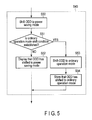
- FIG. 5 is an exemplary flowchart showing a procedure of a device state control process carried out by the electronic apparatus according to the embodiment in the power saving control process of FIG. 4 .
- FIG. 6 is an exemplary flowchart showing procedures of a host-requested identifying process and monitoring process in the electronic apparatus according to the embodiment.
- FIG. 7 is an exemplary flowchart showing a state confirmation process and a monitoring process of a device carried out by the electronic apparatus according to the embodiment.
- an electronic apparatus includes a first device, a first controller, and a second controller.
- the first controller is configured to transit the apparatus between a working state and a hibernation or stand-by state.
- the second controller is configured to shift the first device from an ordinary operation mode to a power saving mode when a first condition is established while the apparatus is in the working state.
- the second controller is configured to shift the first device to the power saving mode without waiting that the first condition is satisfied when the apparatus returns to the working state in which the device is set to the ordinary operation mode after the apparatus shifted to the hibernation state or to the stand-by state in a state that the device is in the power saving mode.
- the electronic apparatus can be realized as various electronic apparatus such as a notebook personal computer, a tablet terminal, and the like. It is assumed below that the electronic apparatus is realized as a notebook personal computer 10 .
- FIG. 1 is a perspective view of a computer 10 with a display unit opened when it is viewed from a front surface side.
- the computer 10 comprises a computer main body 11 and the display unit 12 .
- the display unit 12 is assembled with a display such as a liquid crystal display (LCD) 17 .
- LCD liquid crystal display
- the display unit 12 is attached to the computer main body 11 turnably between an open position at which an upper surface of the computer main body 11 is exposed and a closed position at which the upper surface thereof is covered with the display unit 12 .
- the computer main body 11 comprises a thin box-shaped housing, wherein a keyboard 13 , a touch pad 16 , a power switch 14 configured to turn on and off power of the computer 10 , several function buttons 50 B and 50 C, and speakers 18 A, 18 B are disposed on an upper surface of the housing.
- a USB connector 19 configured to connect a USB is disposed on a right side surface of the computer main body 11 .
- the computer main body 11 comprises an optical disc drive (ODD) 110 .
- ODD optical disc drive
- the ODD 110 is a driver configured to drive an optical disc medium.
- the ODD 110 comprises a tray (disc tray) 110 A on which an optical disc medium 30 is detachable mounted, a spindle motor configured to rotate the optical disc medium 30 , and the like.
- the disc tray 110 A is attached to the housing of the computer main body 11 in order to move between an accommodating position at which the disc tray 110 A is accommodated in the main body 11 and a projecting position at which the disc tray 110 A projects to the outside.
- the ODD 110 is a tray type ODD in which the ODD 110 comprises a disc tray
- the ODD 110 may be a slot-in type ODD.
- the ODD 110 is a CD drive capable of reading a CD or writing to the CD, a DVD drive capable of reading a DVD® or writing to the DVD, a BD drive capable of reading a BD (Blu-ray Disc®) or writing to the BD, or the like.
- FIG. 2 shows a system configuration of the computer 10 .
- the computer 10 comprises, in addition to the ODD 110 , a CPU 111 , a system controller 112 , a main memory 113 , a graphics processing unit (GPU) 114 , a sound codec 115 , a BIOS-ROM 116 , an HDD (hard disc drive) 117 , a BT (Bluetooth (Registered Trademark)) module 120 , a wireless LAN module 121 , an SD card controller 122 , a PCI EXPRESS card controller 123 , an embedded controller/keyboard controller IC (EC/KBC) 130 , and the like.
- the CPU 111 is a processor configured to control operations of components of the computer 10 .
- the CPU 111 executes various software which load into the main memory 113 from the HDD 117 .
- the software comprises an operating system (OS) 201 , a device driver 202 , and various application programs.
- the application programs comprise a power control program 203 and an application program 204 .
- the OS 201 can transit a system state of the computer 10 between a working state and a hibernation or stand-by state in cooperation with a basic input/output system (BIOS) in the BIOS-ROM 116 .
- the working state corresponds to a state S 0 regulated by Advanced Configuration and Power Interface (ACPI) standard.
- the hibernation state corresponds to a state S 4 regulated by ACPI standard, and the stand-by state corresponds to a state S 3 regulated by ACPI standard.
- the OS 201 can shift the computer 10 to the hibernation state or to the stand-by state in cooperation with the BIOS.
- the stand-by state power of almost all the components except the main memory 113 is turned off.
- the hibernation state power of almost all the components comprising the main memory 113 is turned off in a state that the system context such as contents of the HDD 117 , and the like is stored in the main memory 113 .
- Operating the power switch 14 while the computer 10 is in the stand-by state or in the hibernation state returns the system state of the computer 10 from the stand-by state or the hibernation state to the working state using a system context stored in the main memory 113 or a system context stored in the HDD 117 .
- a process for returning the computer 10 from the stand-by state or the hibernation state to the working state is executed by the BIOS and the OS 201 .
- the device driver 202 is a driver configured to control a device in the computer 10 that is to be subjected to the power saving control.
- the device is the ODD 110 , the HDD 117 , the SD card controller 122 , the LCD 17 , or the like.
- the following explanation will be made assuming a case that the device is the ODD 110 .
- the device driver 202 can transit a state of the ODD 110 between an ordinary operation mode and a power saving mode in which the ODD 110 consumes power smaller than that in the ordinary operation mode.
- the ordinary operation mode corresponds to a state D 0 regulated by ACPI standard
- the power saving mode corresponds to a state D 3 regulated by ACPI standard.
- the device driver 202 shifts the ODD 110 to the power saving mode.
- the predetermined condition for shifting the ODD 110 to the power saving mode comprises, for example, not to issue an access request to the ODD 110 for a predetermined period, and the like.
- the device driver 202 returns the ODD 110 to the ordinary operation mode.
- the event for returning the ODD 110 to the ordinary operation mode comprises to press a function button, to press an eject button 52 of the ODD 110 , and the like.
- the computer 10 shifts to the hibernation state or to the stand-by state and when computer returns to the working state, the ODD 110 is reset to the ordinary operation mode.
- the ODD 110 is kept to the ordinary operation mode.
- the device driver 202 has a function for instantly shifting the ODD 110 to the power saving mode without waiting that the predetermined condition for shifting the ODD 110 to the power saving mode when the computer 10 returns to the working state after the computer 10 has shifted to the hibernation state or to the stand-by state in a state that the ODD 110 is in the power saving mode.
- the period in which the ODD 110 is kept in the ordinary operation mode can be minimized, the power consumption of the computer 10 can be reduced.
- the host is a generic term of a parts group or some parts of the group except the ODD 110 disposed to the computer 10 .
- the host is composed of, for example, the CPU 111 , the system controller 112 , the main memory 113 , and the like.
- the host transits the computer 10 to plural states such as the working state, the stand-by state, or the hibernation state in accordance with ACPI standard.
- the device driver 202 carries out a power management of the ODD 110 and the like in cooperation with the power control program 203 . This will be explained in detail referring to FIG. 4 .
- the CPU 111 executes also the basic input/output system (BIOS) in the BIOS-ROM 116 as a non-volatile memory.
- BIOS is a system program for controlling hardware.
- the GPU 114 is a display controller configured to control the LCD 17 used as a display monitor of the computer 10 .
- the GPU 114 creates a video signal to be supplied the LCD 17 from display data in a video memory (VRAM) 114 A.
- VRAM video memory
- the system controller 112 is a bridge device configured to connect between the CPU 111 and the respective components.
- the system controller 112 is built in with a serial ATA controller (SATA controller) 33 configured to control the ODD 110 and the HDD 117 .
- SATA controller serial ATA controller
- the system controller 112 communicates with respective devices on an LPC (Low PIN Count) bus.
- An EC/KBC 130 is a power managing controller configured to manage the power of the computer 10 and realized as a one chip microcomputer built in with a keyboard controller configured to control, for example, the keyboard (KB) 13 , the touch pad 16 , and the like.
- the EC/KBC 130 has a function for turning on and off the power of the computer 10 in accordance with an operation of the power switch 14 by the user.
- a controller 46 is realized by an ODD controller 40 , a control circuit 41 , the power control program 203 , and the like.
- the ODD controller 40 is composed of the device driver 202 , the SATA controller 33 , and the like.
- the controller 46 is connected to the ODD 110 via a junction 42 .
- the controller 46 is connected also to the EC/KBC 130 .
- the junction 42 is an interface capable of connecting the ODD 110 and, for example, a SATA interface.
- the controller 46 is configured to control driving of the ODD 110 .
- the controller 46 has a power saving control function for shifting the ODD 110 to the power saving mode.
- the ODD controller 40 controls the control circuit 41 .
- the control circuit 41 controls the ODD 110 .
- the power control program 203 transmits button information to, for example, the controller 46 or the ODD controller 40 .
- the button information shows that a predetermined function button is pressed.
- the predetermined function button is the button 50 B, the button 50 C, or the like.
- the power saving control function eliminates a useless power consumption in the control circuit 41 or in the ODD 110 .
- the power saving control comprises, for example, the following two functions.
- a first power saving control function is a function for shifting the control circuit 41 and the ODD 110 to the power saving mode when a state that an access request such as a request for reading, writing, and the like from the host to the ODD 110 has continued for a predetermined period and it is determined that the ODD 110 is not used, that is, when only polling of a state of the ODD 110 has continued and the medium 30 is not set to the ODD 110 or is not used even if it is set thereto.
- the ODD controller 40 can secure an operability by the user by confirming that no access request is issued from the host to the ODD 110 and providing a predetermined period until the ODD 110 is shifted to the power saving mode. While the ODD 110 is in the power saving mode, the ODD controller 40 displays that the ODD 110 is in the power saving mode. The ODD controller 40 can notify the user that the ODD 110 is in the power saving mode by, for example, turning on or blinking a lamp 51 and the like or by displaying an icon and the like showing that the ODD 110 is in the power saving mode on the LCD 17 and the like.
- a second power saving control function is a function for causing the ODD controller 40 to shift the control circuit 41 or the ODD 110 from the power saving mode to the ordinary operation mode when an operation such as a depression of a predetermined function button, and the like is carried out.
- the ODD controller 40 can shift the control circuit 41 and the ODD 110 from the power saving mode to the ordinary operation mode when, for example, a function button such as a playback button for reading the medium 30 , and the like or other predetermined function button is pressed.
- a button for example, the eject button 52 and the like disposed to the ODD 110 is pressed, an event signal is sent from the ODD 110 to the controller 46 .
- the ODD controller 40 can shift the control circuit 41 and the ODD 110 from the power saving mode to the ordinary operation mode.
- the power control program 203 comprises a function button controller 43 , a memory controller 44 , and a display controller 45 .
- the power control program 203 carries out various controls in cooperation with the device driver 202 .
- the function button controller 43 instructs the ODD controller 40 to shift the ODD 110 in the power saving mode to the ordinary operation mode based on a signal showing that a predetermined function button supplied from the EC/KBC 130 has been operated.
- the memory controller 44 carries out a control for storing information showing that the ODD 110 is in any of the ordinary operation mode or the power saving mode. For example, when the ODD 110 shifts to the power saving mode or when the ODD 110 in the power saving mode shifts to the stand-by state or the hibernation state, the memory controller 44 carries out a control for storing information showing that the ODD 110 is in the power saving mode in the main memory 113 or in context data in the hibernation state under a control of the device driver 202 . Note that, the following explanation will be made exemplifying a case that the hibernation state is used as a sleep state of the computer 10 .
- the display controller 45 displays that the ODD 110 is in the power saving mode under the control of the device driver 202 while the ODD 110 is in the power saving mode (by turning on or blinking the lamp 51 , displaying an icon, and the like).
- the device driver 202 monitors a state of use of the ODD 110 (step S 40 ). For example, the device driver 202 monitors a state of an access request to the ODD 110 .
- the access request is a request different from the polling, for example, a request of writing to or reading from the ODD 110 , and the like. Otherwise, the access request is a request for fetching the medium 30 from the ODD 110 , and the like.
- the device driver 202 determines whether a shift condition of the ODD 110 to the power saving mode is established based on a monitoring result of an access state (step S 41 ). Although the shift condition will be described later in detail referring to FIG. 6 and FIG.
- the shift condition for example, a condition that no access request is issued to the ODD 110 for a predetermined period may be used. Otherwise, when the condition that no access request is issued to the ODD 110 for the predetermined period and the condition that the medium 30 is not set to the ODD 110 or is not used even if it is set thereto are established, it may be determined that the shift condition is established.
- the shift condition to the power saving mode is not established (step S 41 : NO)
- the device driver 202 monitors again the state of use of the ODD 110 .
- the shift condition to the power saving mode is established (step S 41 : YES)
- the device driver 202 instructs the memory controller 44 to store information showing that the ODD 110 has shifted to the power saving mode (step S 42 ).
- storing the information showing that the ODD 110 has shifted to the power saving mode allows to determine whether or not a state of the ODD 110 just before the computer 10 returns from the hibernation state has been the power saving mode based on the information when the computer 10 was returned from the hibernation state.
- the device driver 202 shifts the ODD 110 from the ordinary operation mode in which the ODD 110 is in an idle state to the power saving mode (step S 43 ). While the ODD 110 is in the power saving mode, the device driver 202 cuts off a direct access to the ODD 110 . Cutting-off the direct access to the ODD 110 means, for example, to cut off the direct access in response to the access request, for example, from the OS 201 to the ODD 110 by the device driver 202 and the device driver 202 makes a response to the direct access to the OS 202 .
- the device driver 202 may shift the ODD 110 to the first power saving mode, and when a different predetermined condition is established, the device driver 202 may shift the ODD 110 to the second power saving mode. In this way, the ODD 110 sequentially shifts to a smaller power consumption mode.
- a time until the ODD 110 is shifted to the power saving mode after the computer 10 has returned to the working state may be shorter than a wait time corresponding to the power saving mode shift condition after the computer 10 has returned to the working state.
- the OS 201 monitors an operating state of the host (step S 44 ).
- the operating state of the host is a state showing whether or not the computer 10 is used.
- the OS 201 determines a transition condition for transiting the computer 10 to the hibernation state is established, that is, whether the idle state of the computer 10 has continued for a predetermined period (step S 45 ).
- the transition condition is not established (step S 45 : NO)
- the OS 201 monitors again the operating state of the host.
- the transition condition is established (step S 45 : YES)
- the OS 201 transits the computer 10 to the hibernation state.
- the power saving mode of the ODD 110 is cancelled and the ODD 110 is set from the power saving mode to the ordinary operation mode by the OS 201 and the like.
- the computer 10 returns to the working state, since the BIOS and the OS 201 need to recognize the ODD 110 , and the like, it is necessary to reset the ODD 110 to the ordinary operation mode.
- the device driver 202 or the controller 46 determines whether or not the ODD 110 has shifted to the power saving mode before the computer 10 enters the hibernation state (step S 46 ).
- the device driver 202 or the controller 46 shifts the ODD 110 to the power saving mode at once by omitting to monitor an access state of the ODD 110 , that is, without waiting that the above shift condition is satisfied.
- step S 46 NO
- the device driver 202 or the controller 46 goes to step S 40 and carries out a monitoring process of the state of use of the ODD 110 to determines whether or not the above shift condition is satisfied.
- the device driver 202 shifts the ODD 110 to the power saving mode (step S 50 ).
- the device driver 202 determines whether or not the ordinary operation mode shift condition (return condition) is satisfied. (step S 51 ).
- the ordinary operation mode shift condition is not (step S 51 : NO)
- the device driver 202 makes a display so that the user can recognize that the ODD 110 is in the power saving mode (step S 52 ).
- the device driver 202 returns the ODD 110 from the power saving mode to the ordinary operation mode (step S 53 ).
- the device driver 202 stores information showing that the ODD 110 is returned from the power saving mode to the ordinary operation mode (step S 54 ). After the process at step S 52 or the process at step S 54 has been finished, the process goes to step S 44 .
- the processing procedure of FIG. 6 shows a processing procedure for determining whether or not the shift condition of the ODD 110 to the power saving mode (first shift condition) is satisfied in the process at step S 41 of FIG. 4 .
- the processing procedure shown in FIG. 6 shows a processing procedure for determining whether or not an access request such as a request for reading, writing, or the like to the ODD 110 from the host has continued for a predetermined period.
- the device driver 202 identifies and monitors the access request from the host to the ODD 110 such as the request for reading, writing, or the like (step S 60 ).
- the device driver 202 determines whether or not the access request is issued from the OS 201 , the application program 204 or the like to the ODD 110 (step S 61 ).
- the application program 204 is an application program capable of issuing the access request to the ODD 110 via, for example, the OS 201 .
- the application program 204 is a data recording/playing application program and the like for writing data to the optical disc medium 30 and reading data from the optical disc medium 30 .
- step S 61 YES
- the device driver 202 identifies and monitors the access request to the ODD 110 from the host again.
- step S 61 NO
- the device driver 202 determines whether or not a state in which the access request to the ODD 110 is not issued has continued for a predetermined period (step S 62 ).
- the device driver 202 returns to step S 60 and identifies and monitors the access request from the host to the ODD 110 again.
- the device driver 202 determines that the shift condition is established and the ODD 110 is not used, that is, only a polling as to a state of the ODD 110 is continued. In this way, the first shift condition is established by the processing procedure shown in FIG. 6 .
- the processing procedure of FIG. 7 shows a processing procedure for determining whether or not a shift condition of the ODD 110 to a power saving mode (second shift condition) is satisfied in the process of step S 41 of FIG. 4 .
- the device driver 202 confirms and monitors the state of the ODD 110 (step S 70 ).
- the state of the ODD 110 is a state of the ODD 110 as a basis for determining whether the ODD 110 is used.
- the device driver 202 determines whether or the disc tray 110 A opens or closes (step S 71 ). When the disc tray 110 A opens (step S 71 : YES), the device driver 202 confirms and monitors the state of the ODD 110 again. When the disc tray 110 A closes (step S 71 : NO), the device driver 202 determines that the ODD 110 is used.
- the ODD 110 is used means, for example, that there is a possibility that the user carries out some operation using the ODD 110 .
- the device driver 202 determines whether or not the medium 30 is set to the ODD 110 (step S 72 ).
- the device driver 202 determines that the ODD 110 is not used and the second shift condition is established.
- the device driver 202 determines whether or not at least a predetermined period has passed after setting the medium 30 to the ODD 110 , whether or not at least a predetermined period has passed after setting the ODD 110 to the ordinary operation mode, or whether or not at least a predetermined period has passed after recognizing setting of the medium 30 to the ODD 110 by the device driver 202 or the host (step S 73 ).
- the process at step S 73 is a process for determining whether or not, for example, the state that the disc tray 110 A closes and the medium 30 is set to the ODD 110 has continued for at least a predetermined period.
- step S 73 When at least the predetermined period has not passed, for example, when the disc tray opens in a period shorter than the predetermined period (step S 73 : NO), the second shift condition is not established and the device driver 202 confirms and monitors the state of the ODD 110 again.
- step S 73 YES
- the second shift condition is established. That is, even if the medium 30 is set to the ODD 110 , when at least the predetermined time has passed without using the ODD 110 , it is determined that a possibility that the ODD 110 is used is low.
- the power consumption when the ODD 110 is in the idle state is 100 mA, whereas the power consumption when the ODD 110 is in the power saving mode is 30 mA.
- the power consumption can be reduced by a power amount based on a function of a product of 70 mA that is a difference between the power consumptions of both the cases and the wait time.
- the power consumption mode when the computer 10 has a function (circuit) for causing, for example, the control circuit 41 to be able to reduce power consumed by the ODD 110 up to 0 mA, since a difference between the power consumption in the idle state and the power consumption the power saving mode becomes 100 mA, the power consumption can be more reduced.
- the device may not be the ODD 110 .
- the device may be the HDD 117 comprising a magnetic disc.
- the second shift condition as explained referring to FIG. 7 , when, for example, the HDD 117 has not been used for a predetermined period without carrying out the processes at step S 71 and step S 72 , it may be determined that the second shift condition is established.
- the device may be an SD card read writer connected to the SD card controller 122 .
- the medium 30 corresponds to the SD card.
- the device driver 202 determines that the SD card read writer is not used and shifts the SD card read writer to the power saving mode.
- the device may be the LCD 17 (panel).
- the device driver 202 determines whether or not a predetermined condition for shifting the LCD 17 to the power saving mode is established, for example, determines whether or not a state that a request for updating a display of the panel is not issued has continued for a predetermined period. As this state, the device driver 202 determines, for example, whether or not the idle state of the computer 10 has continued for a predetermined period, whether or not a state that an input is not issued from an input device has continued for a predetermined period, and the like.
- the device driver 202 shifts the LCD 17 to the power saving mode in which power consumption of the LCD 17 can be reduced by suppressing brightness thereof.
- the above access request comprises a request for updating a display of the panel.
- a display of a screen of the panel becomes dim at once by shifting the panel to the power saving mode at once just after the computer 10 has returned to the working state even if the computer 10 is not in the idle state.
- the power saving mode may be different in each type of the device. Accordingly, when the devices satisfy the shift condition to the power saving mode, the device driver 202 can also shift each of the devices to a mode in which a power consumption is more reduced.
- a device such as the ODD 110 is shifted to the power saving mode just after the computer 10 has returned to the working state, it is sufficient to shift the device such as the ODD 110 to the power saving mode at timing before the wait time corresponding to the power saving mode shift condition after the computer 10 has returned to the working state passes.
- the device when the shift condition is satisfied while the computer 10 is in the working state, the device (ODD 110 ) is shifted from the ordinary operation mode to the power saving mode.
- the computer 10 shifts to the hibernation state or to the stand-by state in a state that a device is in the power saving mode and the computer 10 returns to the working state in which the device is set (reset) to the ordinary operation mode, the device is shifted to the power saving mode without waiting that the shift condition is satisfied.
- the computer 10 mounted with the power saving control system of the embodiment allows to reduce a power consumption until the device is shifted to the power saving state again by returning the computer 10 having been returned to the power saving state at once after it has returned from the hibernation state or the stand-by state.
- power saving energy saving
- the function of the power control program 203 explained in the embodiment may be realized by hardware such as a dedicated LSI or DSP or a microcomputer.
- the procedure of the power saving control process of the embodiment can be entirely executed by software, the same effect as the embodiment can be easily realized only by executing a computer program for executing the procedure of the power saving control process, the computer program being installed on an ordinary computer via a storage medium in which the computer program is stored and which can be read by the computer.
- the various modules of the systems described herein can be implemented as software applications, hardware and/or software modules, or components on one or more computers, such as servers. While the various modules are illustrated separately, they may share some or all of the same underlying logic or code.
Landscapes
- Engineering & Computer Science (AREA)
- Theoretical Computer Science (AREA)
- Physics & Mathematics (AREA)
- General Engineering & Computer Science (AREA)
- General Physics & Mathematics (AREA)
- Power Sources (AREA)
Abstract
Description
Claims (9)
Applications Claiming Priority (3)
| Application Number | Priority Date | Filing Date | Title |
|---|---|---|---|
| JP2013017769A JP6143482B2 (en) | 2013-01-31 | 2013-01-31 | Electronic device and power saving control method |
| JP2013-017769 | 2013-01-31 | ||
| PCT/JP2013/058387 WO2014119008A1 (en) | 2013-01-31 | 2013-03-22 | Electronic device and power-saving control method |
Related Parent Applications (1)
| Application Number | Title | Priority Date | Filing Date |
|---|---|---|---|
| PCT/JP2013/058387 Continuation WO2014119008A1 (en) | 2013-01-31 | 2013-03-22 | Electronic device and power-saving control method |
Publications (2)
| Publication Number | Publication Date |
|---|---|
| US20140215249A1 US20140215249A1 (en) | 2014-07-31 |
| US9164571B2 true US9164571B2 (en) | 2015-10-20 |
Family
ID=51224380
Family Applications (1)
| Application Number | Title | Priority Date | Filing Date |
|---|---|---|---|
| US14/013,758 Expired - Fee Related US9164571B2 (en) | 2013-01-31 | 2013-08-29 | Electronic apparatus and power saving control method |
Country Status (1)
| Country | Link |
|---|---|
| US (1) | US9164571B2 (en) |
Families Citing this family (2)
| Publication number | Priority date | Publication date | Assignee | Title |
|---|---|---|---|---|
| US8984316B2 (en) * | 2011-12-29 | 2015-03-17 | Intel Corporation | Fast platform hibernation and resumption of computing systems providing secure storage of context data |
| KR101747529B1 (en) * | 2015-09-02 | 2017-06-27 | 주식회사 엘지씨엔에스 | Financial device for saving a power and controlling method thereof |
Citations (11)
| Publication number | Priority date | Publication date | Assignee | Title |
|---|---|---|---|---|
| JP2001135009A (en) | 1999-11-04 | 2001-05-18 | Hitachi Ltd | Optical disk device and its control method |
| WO2006098036A1 (en) | 2005-03-17 | 2006-09-21 | Fujitsu Limited | Power conservation control apparatus, power conservation control method, and power conservation control program |
| JP2008262393A (en) | 2007-04-12 | 2008-10-30 | Matsushita Electric Ind Co Ltd | Information processing system and its control method |
| JP2009187606A (en) | 2008-02-05 | 2009-08-20 | Lenovo Singapore Pte Ltd | Tray ejection system of optical disk drive and computer |
| JP2010122875A (en) | 2008-11-19 | 2010-06-03 | Hitachi-Lg Data Storage Inc | Information processor and information processing method |
| US20100257390A1 (en) * | 2007-11-05 | 2010-10-07 | Pioneer Corporation | Information storage device, information recording/reproducing device, and power consumption management method |
| JP2011076641A (en) | 2011-01-20 | 2011-04-14 | Toshiba Corp | Information processing apparatus and power saving effect display method |
| US20120229840A1 (en) | 2011-03-08 | 2012-09-13 | Canon Kabushiki Kaisha | Image processing apparatus, control method therefor, and storage medium storing control program therefor |
| JP2012238166A (en) | 2011-05-11 | 2012-12-06 | Toshiba Tec Corp | Information processing device and program |
| US20140089693A1 (en) * | 2012-09-26 | 2014-03-27 | Eng Hun Ooi | Efficient low power exit sequence for peripheral devices |
| WO2014119008A1 (en) | 2013-01-31 | 2014-08-07 | 株式会社 東芝 | Electronic device and power-saving control method |
-
2013
- 2013-08-29 US US14/013,758 patent/US9164571B2/en not_active Expired - Fee Related
Patent Citations (14)
| Publication number | Priority date | Publication date | Assignee | Title |
|---|---|---|---|---|
| JP2001135009A (en) | 1999-11-04 | 2001-05-18 | Hitachi Ltd | Optical disk device and its control method |
| WO2006098036A1 (en) | 2005-03-17 | 2006-09-21 | Fujitsu Limited | Power conservation control apparatus, power conservation control method, and power conservation control program |
| US20080005461A1 (en) | 2005-03-17 | 2008-01-03 | Fujitsu Limited | Power-saving control apparatus, power-saving control method, and computer product |
| JP2008262393A (en) | 2007-04-12 | 2008-10-30 | Matsushita Electric Ind Co Ltd | Information processing system and its control method |
| US20100257390A1 (en) * | 2007-11-05 | 2010-10-07 | Pioneer Corporation | Information storage device, information recording/reproducing device, and power consumption management method |
| JP2009187606A (en) | 2008-02-05 | 2009-08-20 | Lenovo Singapore Pte Ltd | Tray ejection system of optical disk drive and computer |
| US7929383B2 (en) | 2008-02-05 | 2011-04-19 | Lenovo (Singapore) Pte. Ltd. | Notebook optical disc drive capable of generating a pseudo eject signal |
| JP2010122875A (en) | 2008-11-19 | 2010-06-03 | Hitachi-Lg Data Storage Inc | Information processor and information processing method |
| JP2011076641A (en) | 2011-01-20 | 2011-04-14 | Toshiba Corp | Information processing apparatus and power saving effect display method |
| US20120229840A1 (en) | 2011-03-08 | 2012-09-13 | Canon Kabushiki Kaisha | Image processing apparatus, control method therefor, and storage medium storing control program therefor |
| JP2012186752A (en) | 2011-03-08 | 2012-09-27 | Canon Inc | Information processing apparatus, control method thereof, and control program |
| JP2012238166A (en) | 2011-05-11 | 2012-12-06 | Toshiba Tec Corp | Information processing device and program |
| US20140089693A1 (en) * | 2012-09-26 | 2014-03-27 | Eng Hun Ooi | Efficient low power exit sequence for peripheral devices |
| WO2014119008A1 (en) | 2013-01-31 | 2014-08-07 | 株式会社 東芝 | Electronic device and power-saving control method |
Non-Patent Citations (2)
| Title |
|---|
| An English Translation of the International Search Report mailed by Japan Patent Office on Aug. 7, 2014 in the corresponding PCT application No. PCT/JP2013/058387 and Notification (PCT/IB/311)-3 pages. |
| International Search Report and Written Opinion for application No. PCT/JP2013/058387, dated Apr. 23, 2013. |
Also Published As
| Publication number | Publication date |
|---|---|
| US20140215249A1 (en) | 2014-07-31 |
Similar Documents
| Publication | Publication Date | Title |
|---|---|---|
| US20090112884A1 (en) | Information processing apparatus and control method | |
| US20140173306A1 (en) | System and method for providing for power savings in a processor environment | |
| US20090300396A1 (en) | Information processing apparatus | |
| US9746910B2 (en) | Supporting runtime D3 and buffer flush and fill for a peripheral component interconnect device | |
| US8156263B2 (en) | Information processing apparatus and storage device control method | |
| US20090295810A1 (en) | Information processing apparatus | |
| US20160117269A1 (en) | System and method for providing universal serial bus link power management policies in a processor environment | |
| US20140129759A1 (en) | Low power write journaling storage system | |
| US8560870B2 (en) | Apparatus and method for determining devices used by an application based on a management data, and controlling power state of the determined devices | |
| US9164571B2 (en) | Electronic apparatus and power saving control method | |
| JP4764454B2 (en) | Pen input type information processing apparatus, warning method thereof, and computer-executable program | |
| JP2011134187A (en) | Information processing apparatus | |
| US8145857B2 (en) | Control of access to an external storage device | |
| US20070180284A1 (en) | Electronic device and operation control method | |
| US8713222B2 (en) | Information processing apparatus and power supply controlling method | |
| US20080059825A1 (en) | Information processing apparatus, external storage device and control method | |
| JP6143482B2 (en) | Electronic device and power saving control method | |
| US8176345B2 (en) | Power saving operation for a media drive | |
| JP2012089064A (en) | Electronic apparatus and control method of electronic apparatus | |
| US8605565B2 (en) | Information processing apparatus and operation control method of an information processing apparatus | |
| JP5085493B2 (en) | Information processing apparatus and boot control method thereof | |
| JP4703757B2 (en) | Information processing device | |
| US20090323488A1 (en) | Information-processing apparatus, device, and device setting control method | |
| JP2005346420A (en) | Terminal apparatus | |
| JP2012256364A (en) | Information processor and boot control method therefor |
Legal Events
| Date | Code | Title | Description |
|---|---|---|---|
| AS | Assignment |
Owner name: KABUSHIKI KAISHA TOSHIBA, JAPAN Free format text: ASSIGNMENT OF ASSIGNORS INTEREST;ASSIGNOR:KAWAKAMI, HOSUI;REEL/FRAME:031112/0762 Effective date: 20130827 |
|
| STCF | Information on status: patent grant |
Free format text: PATENTED CASE |
|
| AS | Assignment |
Owner name: TOSHIBA CLIENT SOLUTIONS CO., LTD., JAPAN Free format text: ASSIGNMENT OF ASSIGNORS INTEREST;ASSIGNOR:KABUSHIKI KAISHA TOSHIBA;REEL/FRAME:048720/0635 Effective date: 20181228 |
|
| MAFP | Maintenance fee payment |
Free format text: PAYMENT OF MAINTENANCE FEE, 4TH YEAR, LARGE ENTITY (ORIGINAL EVENT CODE: M1551); ENTITY STATUS OF PATENT OWNER: LARGE ENTITY Year of fee payment: 4 |
|
| FEPP | Fee payment procedure |
Free format text: MAINTENANCE FEE REMINDER MAILED (ORIGINAL EVENT CODE: REM.); ENTITY STATUS OF PATENT OWNER: LARGE ENTITY |
|
| LAPS | Lapse for failure to pay maintenance fees |
Free format text: PATENT EXPIRED FOR FAILURE TO PAY MAINTENANCE FEES (ORIGINAL EVENT CODE: EXP.); ENTITY STATUS OF PATENT OWNER: LARGE ENTITY |
|
| STCH | Information on status: patent discontinuation |
Free format text: PATENT EXPIRED DUE TO NONPAYMENT OF MAINTENANCE FEES UNDER 37 CFR 1.362 |
|
| FP | Lapsed due to failure to pay maintenance fee |
Effective date: 20231020 |