US9096848B2 - Methods and devices for manipulation of target cells using a combined application of acoustical and optical radiations - Google Patents
Methods and devices for manipulation of target cells using a combined application of acoustical and optical radiations Download PDFInfo
- Publication number
- US9096848B2 US9096848B2 US13/671,754 US201213671754A US9096848B2 US 9096848 B2 US9096848 B2 US 9096848B2 US 201213671754 A US201213671754 A US 201213671754A US 9096848 B2 US9096848 B2 US 9096848B2
- Authority
- US
- United States
- Prior art keywords
- cell
- target area
- cells
- membrane
- ultrasound
- Prior art date
- Legal status (The legal status is an assumption and is not a legal conclusion. Google has not performed a legal analysis and makes no representation as to the accuracy of the status listed.)
- Expired - Fee Related
Links
Images


Classifications
-
- C—CHEMISTRY; METALLURGY
- C12—BIOCHEMISTRY; BEER; SPIRITS; WINE; VINEGAR; MICROBIOLOGY; ENZYMOLOGY; MUTATION OR GENETIC ENGINEERING
- C12N—MICROORGANISMS OR ENZYMES; COMPOSITIONS THEREOF; PROPAGATING, PRESERVING, OR MAINTAINING MICROORGANISMS; MUTATION OR GENETIC ENGINEERING; CULTURE MEDIA
- C12N13/00—Treatment of microorganisms or enzymes with electrical or wave energy, e.g. magnetism, sonic waves
-
- C—CHEMISTRY; METALLURGY
- C12—BIOCHEMISTRY; BEER; SPIRITS; WINE; VINEGAR; MICROBIOLOGY; ENZYMOLOGY; MUTATION OR GENETIC ENGINEERING
- C12M—APPARATUS FOR ENZYMOLOGY OR MICROBIOLOGY; APPARATUS FOR CULTURING MICROORGANISMS FOR PRODUCING BIOMASS, FOR GROWING CELLS OR FOR OBTAINING FERMENTATION OR METABOLIC PRODUCTS, i.e. BIOREACTORS OR FERMENTERS
- C12M1/00—Apparatus for enzymology or microbiology
- C12M1/42—Apparatus for the treatment of microorganisms or enzymes with electrical or wave energy, e.g. magnetism, sonic waves
-
- C—CHEMISTRY; METALLURGY
- C12—BIOCHEMISTRY; BEER; SPIRITS; WINE; VINEGAR; MICROBIOLOGY; ENZYMOLOGY; MUTATION OR GENETIC ENGINEERING
- C12M—APPARATUS FOR ENZYMOLOGY OR MICROBIOLOGY; APPARATUS FOR CULTURING MICROORGANISMS FOR PRODUCING BIOMASS, FOR GROWING CELLS OR FOR OBTAINING FERMENTATION OR METABOLIC PRODUCTS, i.e. BIOREACTORS OR FERMENTERS
- C12M35/00—Means for application of stress for stimulating the growth of microorganisms or the generation of fermentation or metabolic products; Means for electroporation or cell fusion
- C12M35/04—Mechanical means, e.g. sonic waves, stretching forces, pressure or shear stimuli
-
- A—HUMAN NECESSITIES
- A61—MEDICAL OR VETERINARY SCIENCE; HYGIENE
- A61N—ELECTROTHERAPY; MAGNETOTHERAPY; RADIATION THERAPY; ULTRASOUND THERAPY
- A61N7/00—Ultrasound therapy
- A61N2007/0039—Ultrasound therapy using microbubbles
-
- C—CHEMISTRY; METALLURGY
- C12—BIOCHEMISTRY; BEER; SPIRITS; WINE; VINEGAR; MICROBIOLOGY; ENZYMOLOGY; MUTATION OR GENETIC ENGINEERING
- C12Q—MEASURING OR TESTING PROCESSES INVOLVING ENZYMES, NUCLEIC ACIDS OR MICROORGANISMS; COMPOSITIONS OR TEST PAPERS THEREFOR; PROCESSES OF PREPARING SUCH COMPOSITIONS; CONDITION-RESPONSIVE CONTROL IN MICROBIOLOGICAL OR ENZYMOLOGICAL PROCESSES
- C12Q2523/00—Reactions characterised by treatment of reaction samples
- C12Q2523/30—Characterised by physical treatment
Definitions
- Ultrasound creates a variety of non-thermal effects on biological tissues ranging from necrotic damage to delicate reversible effects like permeability enhancement and excitable tissue stimulation.
- the present invention in some embodiments thereof, relates to cell manipulation and, more particularly, but not exclusively, to devices and methods of manipulating cells by generating pressure wave(s in proximity thereto.
- a novel mechanism of ultrasound induced intra membrane cavitation is suggested as the reason for ultrasound induced bioeffects in cells, tissue and organ. This mechanism denoted also as Sonophore or Bilayer Sonophore (BLS) suggests that US preferably induces bubble formation in the intra-membrane space between the two lipid leaflets.
- microbubbles can be generated in the body by high intensity ultrasound or introduced intravenously as encapsulated bubbles also known as ultrasound contrast agents (UCA). In-vivo generated microbubbles may improve and widen numerous diagnostic and therapeutic applications in which UCA are currently used. Some of these applications are reviewed by E. Kimmel, Cavitation bioeffects, Critical Reviews in Biomedical Engineering 34 (2006) 105-62, which is incorporated herein by reference.
- ultrasonically induced drug delivery which is based on releasing medication from broken UCAs at a specified location as described in E. Stride, N. Saffari. On the destruction of microbubble ultrasound contrast agents. Ultrasound Med. Biol. 29 (2003) 563-73, which is incorporated herein by reference to and increasing permeability of blood vessel walls for facilitated transport, which is incorporated herein by reference. Also, microbubbles are essential in ultrasonically induced targeted hyperthermia, and diagnostic imaging of specific cells, as well as for increasing membrane permeability of cells for, for instance, gene transfection, see for example R. G. Holt, R. A. Roy.
- High Intensity Focused Ultrasound (HIFU) sources provide enough power density to initiate bubble generation and growth in-vivo.
- An HIFU focal pressure of 4.5 MPa produces detectable bubbles in-vivo, see C. H. Farny, T. Wu, G. Holt, T. W. Murray, R. A. Roy. Nucleating cavitation from laser-illuminated nano-particles. Acoust. Res. Let. Online 6 (2005), which is incorporated herein by reference and referred to herein as Farny (2005).
- S. D. Sokka, R. King, K. Hynynen. MRI-guided gas bubble enhanced ultrasound heating in vivo rabbit thigh. Phys. Med. Biol.
- Gold spherical nanoparticles as well as carbon nano tubes can serve as light-absorbing elements in-vivo because they are biocompatible, conductive and have certain geometrical characteristics that allow them to effectively transform light energy into heat (see Jain et al., see P. K. Jain, I. H. El-Sayed, M. A. El-Sayed. Au nanoparticles target cancer. Nano Today 2 (2007) 18-29, which is incorporated herein by reference.
- microbubble oscillations can enhance local ultrasound energy deposition by two orders of magnitude, see S. Fujishiro, M. Mitsumori, Y. Nishimura, Y. Okuno, Y. Nagata, M. Hiraoka, T. Sano, T. Marume, and N. Takayama. Increased heating efficiency of hyperthermia using an ultrasound contrast agent: A phantom study. Int. J. Hyperthermia 14 (1998) 495-502, which is incorporated herein by reference.
- a method of applying a nondestructive mechanical force on one or more cells in aqueous environment by inducing heat generated acoustic pressure pulses comprising: providing an energy transmission pattern to apply a desired nondestructive mechanical force on a at least one cell in an aqueous environment and synchronizing the radiation of a target area in proximity to the at least one cell in the aqueous environment with ultrasound energy and light energy according to the energy transmission pattern.
- the target area in an intrabody target area is a target area in an intrabody target area.
- the synchronizing comprises synchronizing the radiation of the target area with the ultrasound energy and the light energy with an estimated oscillation pattern of a cell membrane of the at least one cell.
- the synchronizing increases the oscillation amplitude of the cell membrane of the at least one cell in relation to an oscillation amplitude caused by a radiation of the light energy according to the energy transmission pattern without the ultrasound energy.
- the method comprises placing at least one chromophore in the target area.
- the at least one chromophore comprises at least one nanoparticle.
- the at least one chromophore comprises at least one red blood cell.
- the at least one chromophore comprises at least one liposome.
- the synchronizing comprises evaporating liquid in the aqueous environment around the at least one chromophore to form at least one vapor bubble therearound.
- the synchronizing comprises forming a shock wave in the target area.
- the synchronizing comprises forming a pressure pulse as an outcome of rapid thermal expansion without forming a vapor bubble.
- a system of applying a nondestructive mechanical force on one or more cells in aqueous environment by inducing heat generated acoustic pressure pulses comprises a computing unit or a memory which provides an energy transmission pattern and an interface which synchronizes the radiating of a target area in an aqueous environment with ultrasound radiation and focused light radiation according to the energy transmission pattern to form at least one heat generated acoustic pressure pulse that applies a desired nondestructive mechanical force on at least one cell in proximity to said target area.
- a method of applying a nondestructive mechanical force on one or more cells in aqueous environment by inducing heat generated acoustic pressure pulses comprises providing an energy transmission pattern to apply a desired nondestructive mechanical force on at least one cell, radiating a plurality of red blood cells in an intrabody target area in proximity to the at least one cell according to the energy transmission pattern to induce a pressure pulse as an outcome of rapid thermal expansion therearound.
- the radiating comprises synchronizing the radiation of the intrabody target area with ultrasound energy and light energy according to the energy transmission pattern.
- a method of applying a nondestructive mechanical force on one or more cells in aqueous environment by inducing heat generated acoustic pressure pulses comprises providing an energy transmission pattern to apply a desired nondestructive mechanical force on at least one cell and radiating a plurality of liposomes in an intrabody target area in proximity to the at least one cell according to the energy transmission pattern to induce a pressure pulse as an outcome of rapid thermal expansion therearound.
- the radiating comprises synchronizing the radiation of the intrabody target area with ultrasound energy and light energy according to the energy transmission pattern.
- a computerized method of calculating instructions to at least one energy source comprises receiving a desired nondestructive mechanical force to apply on at least one cell in an aqueous environment in proximity to a target area in the aqueous environment, receiving target information defining at least one characteristic the at least one cell, calculating, using a processor, an energy transmission pattern to apply the desired nondestructive mechanical force by forming an heat generated acoustic pressure pulse in the target area, and outputting instructions to allow at least one ultrasound radiation source and at least one focused light source to radiate the target area according to the energy transmission pattern.
- the desired nondestructive mechanical force is a desired nondestructive mechanical force to apply on a cell membrane of the at least one cell.
- the desired nondestructive mechanical force is calculated so as to induce at least one of a periodic inflation and a periodic deflation of an intramembrane space of the cell membrane.
- the aqueous environment is in a human body tissue.
- the at least one cell comprises a nerve cell
- the desired nondestructive mechanical force is set to trigger a stimulation of the at least one cell.
- the at least one cell comprises a nerve cell
- the desired nondestructive mechanical force is set to suppress a stimulation of the at least one cell.
- the desired nondestructive mechanical force is to generate superficial blood vessels in a tissue comprising the at least one cell.
- the desired nondestructive mechanical force is to effect permeability of a membrane of the at least one cell.
- the target information comprises data pertaining to at least one characteristic of at least one chromophore in the target area.
- the calculating is performed according to a heat balance equation calculated for at least one chromophore in the target area.
- the wavelength of light emitted by the at least one focused light source is adapted to the light absorption wavelength of at least one chromophore in the target area.
- Implementation of the method and/or system of embodiments of the invention can involve performing or completing selected tasks manually, automatically, or a combination thereof. Moreover, according to actual instrumentation and equipment of embodiments of the method and/or system of the invention, several selected tasks could be implemented by hardware, by software or by firmware or by a combination thereof using an operating system.
- a data processor such as a computing platform for executing a plurality of instructions.
- the data processor includes a volatile memory for storing instructions and/or data and/or a non-volatile storage, for example, a magnetic hard-disk and/or removable media, for storing instructions and/or data.
- a network connection is provided as well.
- a display and/or a user input device such as a keyboard or mouse are optionally provided as well.
- FIG. 1A is a flowchart of a method for applying nondestructive mechanical force on one or more target cells by inducing heat generated acoustic pressure wave(s) in proximity thereto, for example by forming vapor bubbles, optionally around chromophores, such as nanoparticles, according to some embodiments of the present invention;
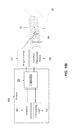
- FIG. 1B is a schematic illustration of a system of applying a nondestructive mechanical force on one or more cells in aqueous environment by inducing heat generated acoustic pressure pulses, according to some embodiments of the present invention
- FIG. 1C is a schematic illustration of a system that uses a high repetition rate light pulses source for applying a nondestructive mechanical force by inducing heat generated acoustic pressure pulses, according to some embodiments of the present invention
- FIGS. 1D and 1E are graphs depicting activation thresholds for exciting cortical neurons by directing light onto chromophores, according to some exemplary embodiments of the present invention.
- FIG. 2 is an isotherm of the temperature of a target area (1° C. over initial temperature) and isobars of a desired mechanical pressure (1 bar gauge) induced by heat generated acoustic pressure waves as a function of the distance of a chromophore from the target area and a radiation period where the pulse energy is 4.28 mJ, the pulse duration is 10 ns, and the focal laser intensity is 18 kJ/cm 2 ;
- FIG. 3 is a graph depicting oscillation of a membrane in response to a shock wave induced by the growing and the collapsing of a vapor bubble around the nanoparticle which is subjected to laser pulse where the membrane diameter is 50 nm, the nanoparticle diameter is 40 nm, and the distance between the particle center and the membrane is 1,000 nm;
- FIG. 4 is a graph depicting ultrasound and shock wave pressures on a surface of a membrane affected by ultrasound transmission and a shock wave from a growing and collapsing vapor bubble around nanoparticle subjected to laser pulse
- the membrane diameter is 50 nm
- the nanoparticle diameter is 40 nm
- the distance between the particle center and the membrane is 1,000 nm
- the Ultrasound acoustic pressure is 1.6 bar
- the ultrasound frequency is 10 MHz
- FIG. 5 is a graph depicting oscillation of membrane affected by ultrasound where the membrane diameter is 50 nm, the acoustic pressure is 1.6 bar and the ultrasound frequency is 10 MHz;
- FIG. 6 is a graph depicting oscillation of membrane affected by ultrasound and shock wave from growing and collapsing vapor bubble around nanoparticle subjected to laser pulse, according to some embodiments of the present invention where the membrane diameter is 50 nm, the nanoparticle diameter is 40 nm, the distance between the particle center and the membrane is 1,000 nm, the ultrasound acoustic pressure is 1.6 bar, and the ultrasound frequency is 10 MHz;
- FIGS. 7A-7B are graphs depicting evolution of the gauge pressure field and temperature around the chromophore (granule), when the Granule diameter is 2 ⁇ m, the Pulse duration is 20 ns, the Laser beam intensity is 2.4 MW/cm 2 , and the absorption efficiency is 0.67, according to some embodiments of the present invention.
- FIGS. 7C-7D are graphs depicting evolution of the gauge pressure field and temperature around the granule, when the Granule diameter is 2 ⁇ m, the Pulse duration is 20 ns, the Laser beam intensity is 2.4 MW/cm 2 , and the absorption efficiency is 1.33, according to some embodiments of the present invention.
- FIG. 8 is a graph depicting an evolution of isobar (1 bar gauge) and isotherm (1° C. over initial temperature) when the granule diameter is 2 ⁇ m, the pulse duration is 20 ns, the laser beam intensity is 2.4 MW/cm 2 and the absorption efficiency is 1.33;
- FIG. 9 is a graph depicting an evolution of isobar (5 bar gauge) and isotherm (5° C. over initial temperature), when the granule diameter is diameter 2 ⁇ m, the pulse duration is 20 ns, the laser beam intensity is 2.4 MW/cm 2 , and the absorption efficiency is 1.33.
- the present invention in some embodiments thereof, relates to cell membrane manipulation and, more particularly, but not exclusively, to devices and methods of manipulating cell membranes by inducing heat generated acoustic pressure wave(s) in proximity thereto.
- метод ⁇ еска ⁇ ированн ⁇ е кар ⁇ ество мо ⁇ ет ка ⁇ ет ка ⁇ ественн ⁇ или ка ⁇ ет ка ⁇ ественн ⁇ или ка ⁇ ет ка ⁇ ественн ⁇ или ка ⁇ ет ка ⁇ ественн ⁇ или ка ⁇ ет ка ⁇ ка ⁇ ет ка ⁇ ка ⁇ ет ка ⁇ ка ⁇ ественн ⁇ ированн ⁇ дл ⁇ дл ⁇ дл ⁇ дл ⁇ дл ⁇ дл ⁇ ⁇ ⁇ ⁇ ⁇ ⁇ ⁇ ⁇ ⁇ ⁇ ⁇ ⁇ ⁇ ⁇ ⁇ ⁇ ⁇ ⁇ ⁇ ⁇ ⁇ ⁇ ⁇ ⁇ ⁇ ⁇ ⁇ ⁇ ⁇ ⁇ ⁇ ⁇ ⁇ ⁇ ⁇ ⁇ ⁇ ⁇ ⁇ ⁇ ⁇ ⁇ ⁇ ⁇ ⁇ ⁇ ⁇ ⁇ ⁇ ⁇ ⁇ ⁇ ⁇ ⁇ ⁇ ⁇ ⁇ ⁇
- a mechanical force is applied on the target cell(s) without exposing them to high intensities of light radiation or waiving the high level of optical resolution, which is typically several orders of magnitude better than acoustic resolution.
- the pressure pulse(s) are created by microbubble formation from opto-acoustic heating of chromophore(s), such as clusters of nanoparticles microparticles, which are placed near the target cell(s), in a safely distance therefrom.
- the heating is optionally performed by a combined action of a modulated, focused laser beam synchronized with an ultrasound beam.
- the heated chromophore(s) boils the surrounding water to form a microbubble.
- a pressure pulse is generated at a close vicinity to the microbubble.
- the laser pulse is synchronized with the ultrasonic pressure pulse and thus the bubble formation and optionally the initial detachment of bilayer membranes in the close vicinity enable to manipulate reversibly the cells with minimal laser and ultrasonic intensity.
- the combination of ultrasonic and laser allows reducing the intensities thereof so that no damage is caused to the target cell(s) and/or the surrounding tissue(s).
- the controlled pressure pulse is large enough to activate the cell and yet not too large to cause any irreversible damage to the cell.
- the combination of ultrasonic and laser allows reducing the intensities thereof below regulatory thresholds and allow increasing the frequency of the ultrasonic radiation. As further described below, the temperature rise is as minimal as possible.
- microbubbles are generated by pulling away the two leaflets while dissolved gas is accumulating in the hydrophobic zone, creating pockets of gas. Stretching of the leaflets that follows the pocket formation was predicted to initiate mechanotransduction processes in the cell; induce pore formation in the membrane and permeability changes, affect mechano-sensitive ion channels, induce polarization in the membrane of excitable cells and affects voltage sensitive ion channels as well. Greater acoustic pressure open passages in the membrane and may induce rupture of membrane proteins in some cases and rupture of the membrane in others. As to excitable cell manipulation, ultrasound of low intensity can activate neuron circuits both in vitro and in vivo.
- the pressure amplitudes which are produced at the neuron membrane level were sufficient to activate the neurons and produce action potentials and subsequent calcium influx into the cells.
- a high resolution is sought for better spatial resolution; for instance when one wants to stimulate an individual cell or a small group of cells.
- the opto-acoustic heating of chromophore(s) stimulates cells in a nondestructive way so that the cells in the target zone are stimulated while cells which are not in the target zone are not stimulated.
- MI mechanical index
- Very high pressure amplitude of few megapascal (MPa) is destructive to the cells; medium level of a couple of hundreds of kilopascals (kPa) can activate the BLS and stimulates cells nondestructively; and lower pressure amplitudes that do not affect the cells at all.
- the opto-acoustic heating which is described herein generates pressure pulses of amplitudes at the target cells that are below the MI threshold for causing damage and as such are nondestructive (depend on the frequency through the MI definition); but still pressure pulses large enough to activate or stimulate the target cells for e.g. producing action potential in nerve cells or muscle cells.
- all the non target cells which are far from the nanoparticle or the chromophore illuminated by the focused light, and do not sense the every localized effect of the laser pulse heating will not be activated and will stay at their natural/neutral state. This way, optical resolution, which is typically several orders of magnitude better than acoustic resolution, is achieved.
- the chromophore(s) which are used for microbubble formation are red blood cells (RBCs).
- RBCs red blood cells
- the microbubble formation is an outcome of the periodic inflation of the intramembrane space around the RBCs, for example in capillaries near the target cells whereas focused light source or laser beam with wavelength that is typically absorbed more in the hemoglobin of the RBCs causes a slight temperature rise in the RBCs and increases their tendency to develop a gas envelope therearound under the combined action of a focused heating source and ultrasound.
- ultrasound and light radiation may be generated by single sources or distributed sources, for example phased arrays or spatialized modulators.
- the chromophore(s) which are used for microbubble formation are heat sensitive liposomes.
- the bubble generation is triggered as for RBCs.
- the liposomes are placed at a safe distance of few micrometers from the target cells. Liposomes can be targeted to attach to the target cells using ligands.
- the instructions are set in a manner that the radiation of the target area forms pressure waves, optionally optoacoustic, that apply a desired nondestructive mechanical force on the membrane of one or more cells in an aqueous environment, for example an intrabody tissue.
- This desired nondestructive mechanical force optionally triggers inflation and/or deflation, optionally periodic, of the intramembrane space as the two leaflets of the bilayer membrane that encloses the cell, the nucleus and other cell organelle such as the mitochondria, detaches and attaches periodically.
- a nondestructive mechanical force is a mechanical force which is applied on the membrane of cells without forming irreversible raptures.
- target information defining one or more characteristics of the cell(s), for example the membrane and/or additional information are received and used for calculating an energy transmission pattern to apply the desired nondestructive mechanical force by forming one or more pressure waves in proximity to cells.
- the instructions are then forwarded to the one or more energy sources which radiate accordingly the target area.
- chromophore(s) such as gold nanoparticle(s) and/or oxy-hemoglobin in the red blood cells with and/or without ultrasound radiation.
- chromophore(s) such as gold nanoparticle(s) and/or oxy-hemoglobin in the red blood cells with and/or without ultrasound radiation.
- the targeting of a target area may be performed by synchronizing light intensity and ultrasonic intensity.
- each one of the transmission has less or no effect on areas around the target area.
- BLS manipulation is made by radiating chromophores, with light (laser) and ultrasound radiation, while the laser is synchronized with the ultrasound to produce microbubbles around the chromophores.
- a nondestructive mechanical force on a cell membrane of one or more cells in aqueous environment by inducing heat generated acoustic pressure wave(s) in proximity thereto.
- an energy transmission pattern which is set to apply a desired nondestructive mechanical force on a cell membrane of one or more cells in an aqueous environment.
- a target area in proximity to the cells is radiated with synchronized ultrasound and focused light energy according to the energy transmission pattern.
- the synchronization allows reducing the focused light energy or the ultrasound energy which has to be radiated in proximity to the cells for applying the desired nondestructive mechanical force separately.
- the temperature of the cells is not substantially increased during the radiation thereof.
- synchronization between the focused light energy and the ultrasound energy may extend the oscillation period and increase the expansion of the membrane in relation to the oscillation period and the expansion of the membrane when energy of only one of the energy types is applied.
- An exemplary system includes a computing unit which calculates an energy transmission pattern to apply a desired nondestructive mechanical force on a cell membrane of at least one cell in an aqueous environment and an interface which synchronizes the radiating of a target area in proximity to the cells with ultrasound energy and light energy according to the computed energy transmission pattern.
- a nondestructive mechanical force on a cell membrane of one or more cells by using a plurality of red blood cells as chromophores.
- a plurality of red blood cells in an intrabody target area in proximity to target cell(s) are radiated according to an energy transmission pattern to induce a pressure pulse as an outcome of rapid thermal expansion therearound.
- FIG. 1A is a flowchart 100 of a method for calculating instructions for applying nondestructive mechanical force on target cell(s), for example cell membrane(s) of one or more target cells, in aqueous environment, for example an intrabody tissue by generating pressure pulses, optionally optoacoustic, in proximity thereto, for example by changing the temperatures of area(s) in the aqueous environment or forming vapor bubbles, optionally around chromophores, such as nanoparticles, according to some embodiments of the present invention.
- the resulting pressure pulses induce a revisable, nondestructive mechanical manipulation of the target cell(s).
- an heat generated acoustic pressure is a pressure which is applied by a thermal expansion and/or bubble(s) formed, optionally around chromophore(s) and induced, for example, by a combination of thermal expansion that follows light heating and applied ultrasound radiation and/or by a high repetition rate light pulses source, such as laser.
- a chromophore is a light absorbing element, such as nanoparticle(s).
- the pressure pulses which are heat generated acoustic pressure pulses, are generated by simultaneously irradiating a target area with ultrasound energy, for example a focused beam of ultrasound, and light, for example a laser beam.
- ultrasound energy for example a focused beam of ultrasound
- light for example a laser beam.
- the transmissions of ultrasound energy and light are synchronized in order to reduce potential damage to the target tissue(s).
- chromophores such as nanoparticles
- heating of chromophores, such as nanoparticles by a laser pulse using energy density greater than 100 mJ/cm 2 , could induce vaporization and generate microbubbles.
- the same result may be achieved by using ultrasound alone with acoustic pressure 4.5 MPa.
- ultrasound is introduced at the same time as the laser pulse, less laser power is required and both acoustic pressure and laser energy are reduced to e.g. 5 mJ/cm 2 and 0.6 MPa correspondingly.
- a relatively high frequency is needed. For instance, a typical focus size of a focused beam of ultrasound at 1 MHz is about 1 millimeter.
- a separating gel coating for example targeting the nanoparticles to the right group of cells can also be done by means of special ligand coating in vicinity to the microbubble.
- the laser pulse should be given at about the time when the acoustic pressure is minimal, because the phase transition, i.e. evaporation/boiling occurs then at the most favorable conditions and the energy needed to generate a bubble is minimal (for the given acoustic pressure pulse). As a result of the synchronization, this energy range is safe to be applied in-vivo and as such applicable for in vivo treatments. It should be noted that when vapor bubble(s) are forms, the amplitude of pressure pulse(s), such as heat generated acoustic pressure pulse(s), is substantially higher than the amplitude of similar pressure pulse(s) when no vapor bubble(s) are formed.
- the nondestructive mechanical force is formed by changing the pressure that is applied on the cell membrane in the aqueous environment, for example by increasing vapor pressure around or near chromophores to boil locally the aqueous environment therearound and/or by heating areas in the aqueous environment using light pulses.
- the process starts from heating of the chromophores with the energy delivered by one or more laser beams. In case vapor bubbles are formed, when the temperature of the chromophores reaches the boiling point of the surrounding liquid in the aqueous environment, vapor appears around the chromophores and when the irradiation ceases the vapor cools and collapses.
- FIG. 1B is a schematic illustration of a system 99 of applying a nondestructive mechanical force on one or more cells 90 in aqueous environment by generating heat generated acoustic pressure pulses, according to some embodiments of the present invention.
- the system 99 is optionally used to implement the method depicted in FIG. 1B and/or used for applying precalculated and/or preset heat generated acoustic pressure pulses.
- the system 99 is a neuro-stimulation device where the heat generated acoustic pressure pulses apply different mechanical forces on a neural tissue, for example as a neural interface.
- the system 99 is set to operate an acoustic wave source 98 , such as a probe that includes a transducer or an array of ultrasound transducers each optionally separately controllable to be activated independently in a different fashion.
- the acoustic wave source may include an ultrasound source, such as a focused ultrasound (FUS) source, a high-Intensity focused ultrasound (HIFU) source and/or a magnetic resonance-guided focused Ultrasound (MRgFUS) source.
- This probe may be referred to herein as an ultrasonic source.
- the system 99 is set to operate a focused light source 97 , such as a laser source.
- the system 99 optionally includes a computing unit 93 which calculates an energy transmission pattern to generate optoacoustic pulse(s) in a target area where the optoacoustic pulse is calculated to apply a desired nondestructive mechanical force on one or more target cells, optionally of an intrabody tissue, in proximity to the target area. Additionally or alternatively instructions which follow such an energy transmission pattern are stored in a memory 92 of the system 99 .
- the system 99 further includes an interface, such as a controller 95 that synchronizes the radiating of the target area in proximity to the target cells with synchronized ultrasound and light radiations according to said energy transmission pattern to form optoacoustic pulse(s) in the target area.
- the system 99 applies the energy which induces heat generated acoustic pressure in a target area 89 or a target space in proximity to one or more selected cells 91 which are optionally part of a tissue 90 .
- the heat generated acoustic pressures may be selected according to a desired bioeffect, for example neural stimulation, and/or neural inhibition or a desired diagnosis.
- the cells may be in various tissues in a target organ or a part of a target organ, such as the brain, the eye and optionally the retina there therein, and/or any other neural system or network.
- the stimulation and/or inhibition may be used for restoring and/or creating a composite sensory perception for people who have a major deficiency in their sensory systems, such as blindness or deafness with varying degrees.
- a desired impact on the target cell(s), for example the cell membranes of one or more cells is provided.
- the desired impact is optionally adjusting the membrane surface tension of the cell(s) to a desired level, optionally for a desired period.
- a desired impact is optionally applying a nondestructive mechanical force on the membrane surface of nerve and/or muscle cells and any other cells including endothelial cells, epithelial cells and bone cells (osteocytes) so as to change their membrane tension.
- the change opens and/or closes ion channels on the cell membrane, regulates the flow of ions across the membrane.
- the desired impact is applying a nondestructive mechanical force that opens a gate that controls the ion flow via the ion channels.
- pores might form in the membrane as a result of exposure to US and this can enhance membrane permeability and allows greater rates of transport of drugs.
- Any mechanical stimulation of the cell by the pulsating intra-membrane space can activate cascades of mechano-transduction processes in the cells which are in particular known as mechano-sensitive like Endothelial cells in the blood vessels, which are sensitive to shear stress, stretching force and pressure; Osteocytes in the bone and Chondrocytes in the particular cartilage which are sensitive to compression forces, and many others.
- desired impacts are patterned auditory neuron stimulation for inner ear prosthesis, patterned retinal neuron stimulation for retinal prosthesis, patterned three dimensional stem cell differentiation on a tissue engineering scaffold for organ architecture, activation of implanted nerve prosthesis for nerve activation for muscle activation, activation of implanted pacemaker, and/or skin rejuvenation.
- this information includes information about particles which around or near which the vapor bubbles may be formed, for example a potential of absorbing laser power by the chromophore, heating temperature(s), melted particle mass, chromophore total mass, and/or chromophore radius, information about the surrounding liquid, for example volume expansion coefficient(s) (also known as thermal expansion coefficient), density and/or dynamic viscosity of the liquid, initial temperature of vaporization, the latent heat of vaporization/condensation, and information about the power source that is used for generating the heat generated acoustic pressure pulse(s), for example the laser pulse width of a used laser sources, including scanners and holographic, and/or ultrasonic source.
- volume expansion coefficient(s) also known as thermal expansion coefficient
- density and/or dynamic viscosity of the liquid initial temperature of vaporization
- the latent heat of vaporization/condensation and information about the power source that is used for generating the heat generated acoustic pressure pulse(s), for
- This target information may be provided in advance, for example taken from a repository, such as a memory that hosts a plurality of different target information, each for another cell and/or for achieving a different impact on the target cells.
- an energy transmission pattern that is needed to achieve the desired impact is calculated and/or selected.
- the calculation is based on the heat transfer and/or vaporization, the bubble and/or fluid dynamics, and/or dissolved gas transport. The calculation allows predicting the magnitude of the generated heat generated acoustic pressure pulse(s) and optionally the bubble stability when needed, and to define conditions for more effective heat generated acoustic pressure pulse(s) generation in terms of laser power and optionally ultrasound acoustic pressure.
- the energy transmission pattern includes instructions to one or more power source(s) to radiate the environment around the cells, for example with chromophores as outlined above and further described below.
- the energy transmission pattern optionally defines the wavelength and/or the transmission period of the radiated energy.
- the energy transmission pattern is set so that temperature of the target cell(s) is not changed and/or not substantially changed.
- FIG. 2 is an isotherm of the temperature of a target area and isobars of a desired mechanical pressure generated by heat generated acoustic pressure as a function of the distance of a chromophore from the target area and a radiation period.
- the graph allows calculating an energy transmission pattern wherein the temperature of the target area does not substantially increase while the desired mechanical pressure is achieved.
- the isobar is 1 bar gauge
- the isotherm is 1° C. over the initial temperature
- the pulse duration is 20 ns
- laser beam intensity 2.4 MW/cm 2 and an absorption efficiency.
- FIG. 1A Reference is now made, once again, to FIG. 1A .
- instructions to one or more energy source are set according to the calculated energy pattern. These instructions instruct a light source, such as a laser source, and optionally an ultrasound source to radiate a target area in proximity to the target tissue(s) according to the energy transmission pattern.
- the radiation is optionally performed on one or more chromophores, which are placed in a common aqueous environment with the target tissue(s).
- the chromophores are intrinsic to the tissue of the target cell(s).
- flavoproteins may be used as chromophores to form heat generated acoustic pressure in proximity to cells of certain tissues.
- the chromophores may be melanin or Retinal pigment epithelium (RPE).
- the above method allows forming pressure pulses, optionally optoacoustic, that apply a desired mechanical pressure on target cells.
- the desired mechanical pressure is set for a desired reversible manipulation, such as a membrane manipulation, for example an inflation and/or deflation, optionally periodic, of the intramembrane space as the two leaflets of the bilayer membrane that encloses the cell.
- the membrane is then stretched, cell fibers and the cytoskeleton are loaded, and tension and compression of membrane proteins is changed.
- cell(s) may be mechanically manipulated to change functioning. This may be used for stimulating nerve cells and adjusting tissue permeability, for example for changing drug delivery rates.
- the stimulation may be applied on blood-brain barrier (BBB) cells for effecting its operation and/or on broken bones and/or wounds to urge their healing rate and/or the like.
- BBB blood-brain barrier
- high spatial resolution (micrometer-scale) as well as high temporal resolution (sub-millisecond) of the pressure pulses allows manipulating groups of nerve cells that carry the signals to the brain from the retina in retinal implants and from the ear in cochlear implants.
- ear implants are quite limited in their performance while retinal implants are still being developed.
- Various types of nondestructive stimulation of cells by US may be an outcome of the effect of the pressure pulse on the BLSs in and around the cell. Same effects can be produced by pressure pulse that were not produced by US only but that were generated by the combined action of a microbubble created around or near a laser heated nanoparticle e.g.
- a method for a combined action of laser induced chromophore heating that produces a heat generated acoustic pressure pulse (through a pulsating bubble around a heated nanoparticle or by a thermal expansion of the tissue) that is synchronized with the US pressure pulse and both act together on the cells in the target zone like US does, to stimulate them nondestructively is a safe method for cell modulation of functioning with a very high spatial resolution.
- This optoacoustic radiation sources may be placed more than few millimeters from the target area, for example several centimeters away and has no influence on the tissue(s) surrounding the target area.
- the effect of the optoacoustic pulse may be intensified.
- the formation of the pulse is optionally coordinated with the oscillation of the membrane to increase the effect of the optoacoustic pulse and/or to allow applying less mechanical force on the cell(s).
- the combined action of the light-induced heating and ultrasound induced mechanical effect can also be synergistic at the biological level.
- heating can lead to superthreshold response (e.g. intracellular calcium release or membrane potential change) in a subset of cells, which the mechanical effect compounds to a superthreshold event.
- superthreshold response e.g. intracellular calcium release or membrane potential change
- the heat generated acoustic pressure pulses are induced using a heat generated acoustic pressure source, such as a laser, and optionally without any independent acoustic energy source.
- a heat generated acoustic pressure source such as a laser
- FIG. 1C is a schematic illustration of a system 199 that uses a high repetition rate light pulses source 55 for applying a nondestructive mechanical force by inducing heat generated acoustic pressure pulses, according to some embodiments of the present invention.
- 1C further depicts the high repetition rate light pulses source 55 , for example a laser source, that is controlled by the controller 95 instead of the light source 97 and the acoustic/ultrasonic source 98 .
- the high repetition rate light pulses source 55 is instructed by the controller 95 to generate pulses or is modulated at a rate of 100 kHz or more, causing a periodic cavitation around each chromophore to stimulate the cells.
- the high repetition rate light pulses source 55 transmits a pulsating and/or a temporally-modulated light beam or light pattern toward at the target area 89 .
- the modulation rate of the transmission is higher than a natural cavitation frequency of the chromophore, for example the rate is higher than 100 kHz and slower than 1 MHz, for example about 30 MHz, 50 MHz, 65 MHz, and 80 MHz.
- the system 199 may be used to stimulate or otherwise modulate the activity of a cell, such as a nerve, for example in primary sensory cortices or in the retina and auditory cochlea.
- a cell such as a nerve
- FIGS. 1D and 1E are graphs depicting activation thresholds (normalized energy and power) for exciting cortical neurons by directing light onto chromophores, such as black microparticles
- Line 343 is related to a continuous laser and line 345 is related to a repetition rate light pulses source, a rapidly pulsed laser with a pulse rate of pulse per 12.5 nanoseconds (80 MHz).
- the rapidly pulsed laser has excitation thresholds which are more effective in driving neural activity when excitation is performed at low durations (e.g. less than 200 microseconds).
- excitation thresholds which are more effective in driving neural activity when excitation is performed at low durations (e.g. less than 200 microseconds).
- an acoustic wave with a frequency of 500 kHz (+ ⁇ 200 kHz) is generated by the chromophores in response to a pulsating laser (not during a CW pulse) coactivation of acoustic and photo-thermal energy generated at the chromophores is responsible for lower activation thresholds.
- some of the equations include mathematical description of a vaporization process for forming for a vapor bubble in proximity to the target cells, for example around or near one of the plurality of nanoparticles.
- the mathematical description is for developing a vapor bubble around a single chromophore, however can be used for developing vapor bubbles around a plurality of chromophores.
- equations include mathematical description of generating mechanical pressure on target cells by heat generated acoustic pressure pulses which heat one or more areas in proximity thereto, for example around one of the plurality of chromophores.
- Equation ⁇ ⁇ 1 ⁇ T L ⁇ t D L r 2 ⁇ ⁇ ⁇ r ⁇ ( r 2 ⁇ ⁇ T L ⁇ r ) ; ⁇ ⁇ 0 ⁇ t ⁇ t 0 ; ⁇ ⁇ R p ⁇ r ⁇ ⁇ .
- T L denotes surrounding liquid temperature
- t and r denote time and space coordinates
- D L denotes heat diffusivity of the surrounding liquid
- t 0 denotes a moment when the evaporation begins.
- the boundary conditions are of temperature continuity on the particle surface:
- Equation 2 T L
- T p denotes the temperature of the particle when the temperature away from the cell membrane is:
- Equation 3 T L
- the initial condition is:
- Equation 4 T L
- a lumped heat balance equation for the particle is:
- r R p
- the lumped heat balance consists the accumulation of the heat term on the left hand side (LHS) of Equation 5 and the source term q and heat loss by conduction to the surrounding liquid on the right hand side (RHS) of Equation 5.
- Equation 6 T p
- T p T s0
- T s0 T s (p s0 ) denotes the initial temperature of vaporization
- p s0 is the corresponding vapor pressure
- Equation ⁇ ⁇ 7 p s ⁇ ⁇ 0 P amb + 2 ⁇ ⁇ ⁇ ( T s ⁇ ⁇ 0 ) R p .
- a spherical layer of vapor starts to form around or near the particle with an inside radius R p and outside moving boundary with a radius R that varies in time.
- a heat transfer problem becomes a two-phase problem with a vapor layer having a thickness of R ⁇ R p and a liquid surrounding the vapor layer.
- the moving boundary acts like a moving spherical piston pushing liquid outward symmetrically when the vapor layer expands.
- Mass conservation of incompressible fluid dictates that the outward flow velocity at radius r is proportional to r ⁇ 2 .
- the heat transfer equation for the surrounding liquid is, therefore:
- Equation 9 T L
- Equation ⁇ ⁇ 10 p s p amb + 2 ⁇ ⁇ ⁇ ( T s ) R .
- the radius of the vapor bubble changes as a result of vaporization/condensation on its boundary
- r R + 0 ;
- t* denotes the time when the vapor bubble appears
- L denotes the latent heat of vaporization/condensation
- q H denotes the heat flux from the vapor to the vaporization/condensation boundary.
- the heat flux from the particle to the vapor layer (q H ) can be expressed by:
- T s is the vaporization temperature
- k g is the heat conductivity of the vapor/air mix.
- ⁇ denotes convective heat transfer coefficient for the case when there is a space between two spherical surfaces, see H. Y. Wong, Handbook of essential formulae and data on heat transfer for engineers, Longman, London and New York. 1977, which is incorporated herein by reference.
- the evaporation is performed according to a heat balance equation calculated per particle.
- the heat balance equation may be adapted to the melting temperature of the used nanoparticle.
- the heat balance equation is as follows:
- Equation ⁇ ⁇ 16 4 3 ⁇ ⁇ ⁇ ⁇ R p 3 ⁇ c p ⁇ ⁇ p ⁇ d T p d t q - 4 ⁇ ⁇ ⁇ ⁇ R p 2 ⁇ q H . ( 16 )
- m m denotes a melted mass of the nanoparticle
- Equation 19 r m
- L pm denotes a melting latent heat of the particle material
- q m denotes power absorbed by the melted particle from laser.
- T p T pm is assumed.
- Equation 22 r v
- L pv denotes vaporizing latent heat of the particle material
- R pm denotes a to radius of non vaporized part of the particle
- q v denotes power absorbed by this part.
- R ⁇ ( 1 - u C ) ⁇ d u d t + 3 2 ⁇ u 2 ⁇ ( 1 - u 3 ⁇ C ) 1 ⁇ L ⁇ [ ( 1 + u C ) ⁇ ( p g - P 0 - 2 ⁇ ⁇ R - 4 ⁇ ⁇ L R ⁇ u ) + R C ⁇ ( d p g d t + 2 ⁇ ⁇ R 2 ⁇ u + 4 ⁇ ⁇ L R 2 ⁇ u 2 - 4 ⁇ ⁇ L R ⁇ d u d t ) ] .
- the pressure inside the shell of the bubble is calculated by summing partial pressures of the vapor and the air diffusing from the surrounding liquid:
- n v and n a denote the mole contents of the vapor and air correspondingly.
- the vapor mole content inside the bubble is connected with thickness of the vaporized liquid:
- ⁇ v denotes vapor molecular weight
- the mole content of the air inside the bubble is determined by the mass balance:
- G a denotes a volume rate of the air leaving the bubble
- ⁇ a and ⁇ a denote air molecular weight and density respectively
- D a denotes the diffusivity of the air in the surrounding liquid
- C a denotes mole concentration of the air in the surrounding to liquid.
- Equation 31 C a
- C s denotes air concentration on the bubble surface. It is assumed that C s equals the saturation concentration, see A. Eller and H. G. Flynn, “Rectified diffusion during nonlinear pulsations of cavitation bubbles” in J. AcoustSoc Am. 37, 493-503 (1965), which is incorporated herein by reference.
- the saturation concentration is related to the air partial pressure by Henry's law:
- the collapse of a vapor bubble may be accompanied by high gas pressure inside the vapor bubble, which in turn causes spreading of shock waves in vicinity of the vapor bubble.
- Parameters of the shock waves may be estimated based on the Kirkwood-Bethe approximation (see R. T. Knapp, J. W. Daily and F. Hammit: “Cavitation”. McGraw-Hill New York, 1970), which are incorporated herein by reference.
- the equations of continuity and motion for surrounding liquid are:
- Parameter y preserves its value along characteristic traced by a point moving with velocity C+ ⁇ .
- C( ⁇ ) denotes a local sound velocity:
- ⁇ l denotes a density of surrounding liquid
- ⁇ l denotes a dynamic viscosity of the liquid
- ⁇ s denotes a dynamic viscosity of the membrane
- ⁇ 0 denotes initial thickness of the membrane
- P st denotes pressure attributed to surface tension
- R denotes the membrane curvature radius, connected with the membrane deviation H, and the membrane radius a as:
- ⁇ 1 and ⁇ 2 denote surface tension at the air-membrane and liquid-membrane interfaces respectively
- P sh denotes a shock wave pressure caused by evolution of the vapor bubble
- P ar denotes a pressure caused by attraction/repulsion forces
- P in denotes the internal gas pressure
- ⁇ s denotes dynamic viscosity of the to membrane
- ⁇ 0 denotes initial thickness of the membrane.
- a focused light source that heats a natural chromophore, for example a cluster of hemoglobin molecules in the RBC, pigmented granules in the eye retina, and/or heat sensitive liposomes.
- a natural chromophore for example a cluster of hemoglobin molecules in the RBC, pigmented granules in the eye retina, and/or heat sensitive liposomes.
- the natural chromophore light absorption efficiency is much higher than the surrounding tissue.
- up to 90% of the radiation energy is absorbed by melanoprotein granules of spherical and spheroidal shape and sizes of about 0.5-1 ⁇ m.
- the light intensity is low enough such that no boiling is induced and no vapor bubble is generated. Only a pressure pulse that accompanies the rapid thermal expansion and contraction is applied.
- the power absorbed by the particle may be expressed as:
- K ab denotes the absorption efficiency
- S p denotes geometrical cross section of the particle.
- the heat transfer equation for the particle—surrounding tissue system is:
- W/m 3 denotes a specific laser power absorbed.
- q 0 is a specific laser power absorbed by the particle.
- c c b at 0 ⁇ r ⁇ a and c L at r>a
- D equals D b at 0 ⁇ r ⁇ a and D L at r>a
- c equals c b at 0 ⁇ r ⁇ a and c L at r>a.
- B B b at 0 ⁇ r ⁇ a and B L at r>a
- ⁇ equals ⁇ b at 0 ⁇ r ⁇ a and ⁇ L to at r>a
- ⁇ denotes a potential of displacements
- composition or method may include additional ingredients and/or steps, but only if the additional ingredients and/or steps do not materially alter the basic and novel characteristics of the claimed composition or method.
- a compound or “at least one compound” may include a plurality of compounds, including mixtures thereof.
- range format is merely for convenience and brevity and should not be construed as an inflexible limitation on the scope of the invention. Accordingly, the description of a range should be considered to have specifically disclosed all the possible subranges as well as individual numerical values within that range. For example, description of a range such as from 1 to 6 should be considered to have specifically disclosed subranges such as from 1 to 3, from 1 to 4, from 1 to 5, from 2 to 4, from 2 to 6, from 3 to 6 etc., as well as individual numbers within that range, for example, 1, 2, 3, 4, 5, and 6. This applies regardless of the breadth of the range.
- a numerical range is indicated herein, it is meant to include any cited numeral (fractional or integral) within the indicated range.
- the phrases “ranging/ranges between” a first indicate number and a second indicate number and to “ranging/ranges from” a first indicate number “to” a second indicate number are used herein interchangeably and are meant to include the first and second indicated numbers and all the fractional and integral numerals therebetween.
- the membrane diameter is 50 nm
- nanoparticle diameter is 40 nm
- the distance between the particle center and the membrane 1,000 nm (distance between the particle center and the membrane) no ultrasound was applied, only laser pulse.
- the figure depicts oscillation of the membrane in response to shock wave induced by the growing and collapsing of a vapor bubble around the nanoparticle which is subjected to laser pulse.
- FIG. 4 Two shock waves, 1 micrometer away from the nanoparticle, are shown in FIG. 4 , at the BLS, by the colored pink line which is marked with the title “shock wave pressure”.
- the membrane diameter is 50 nm
- the nanoparticle diameter is 40 nm
- the distance between the particle center and the membrane is 1,000 nm
- the ultrasound acoustic pressure is 1.6 bar
- the ultrasound frequency is 10 MHz.
- the shock wave is attributed to a sudden expansion of the microbubble that accompanies the beginning of the boiling/evaporation stage, and the second that results from the sudden collapse of the microbubble as it cools down.
- the deformation of the membrane that is induced by the two shock waves is depicted in FIG. 5 that depicts the oscillation of membrane affected by ultrasound where the membrane diameter is 50 nm, the acoustic pressure is 1.6 bar and the ultrasound frequency is 10 MHz.
- the deformation is typified by a relatively long and large expansion followed by a train of smaller and rapid expansions and contractions, also known as ringing.
- the combined mode of a laser pulse given together and synchronized with ultrasound is shown in FIG.
- the membrane diameter is 50 nm
- the nanoparticle diameter is 40 nm
- the distance between the particle center and the membrane is 1,000 nm
- the ultrasound acoustic pressure is 1.6 bar
- the ultrasound frequency is 10 MHz.
- FIGS. 7A-7B are graphs depicting evolution of the gauge pressure field and temperature around the chromophore (granule), when the granule diameter is 2 ⁇ m, the pulse duration is 20 ns, the laser beam intensity is 2.4 MW/cm 2 , and the absorption efficiency is 0.67.
- FIGS. 7C-7D are graphs depicting evolution of the gauge pressure field and temperature around the granule, when the granule diameter is 2 ⁇ m, the pulse duration is 20 ns, the laser beam intensity is 2.4 MW/cm 2 , and the absorption efficiency is 1.33.
- FIGS. 7A-7D show evolution of isobar (1 and 5 bar gauge respectively) and isotherm (1° C. and 5° C.
- the granule diameter is 2 ⁇ m
- the pulse duration is 20 ns
- the laser beam intensity is 2.4 MW/cm 2
- the absorption efficiency is 1.33.
Abstract
Description
T L|r=R
T L|r=∞ =T ∞. (3)
T L|t=0 =T ∞. (4)
q L for 0<t<t w;
q=0 for t>t w;
T p|t=0 =T ∞.
T L|r=R =T s(p s).
and expansion/collapse due to the pressure difference across the water/vapor boundary
R t=t* =R p;
q H=α(T p =T s)
denotes the particle total mass. In such embodiments, the following heat balance to equation may be used:
with initial condition:
r m|t=t
r v|t=t
and ρL and ηL denote respectively density and dynamic viscosity of the liquid, and C denotes sound velocity in the gas. Optionally, when light pulses are applied simultaneously with ultrasound radiation and the ambient pressure is expressed as follows:
R=R p ;u=0.
p g =p v +p a +p p;
C a(r,0)=C i ;r>R p; and
C a|r=R =C s ;t>0.
y=r(h+v 2/2)
-
- where {dot over (r)}=ν+C.
Impact on the Cell Membrane
Q=K ab S p I.
- q0; 0<r<a; 0<t<tp;
- q=0; a 21 r<∞; 0<t<∞
- 0; 0<r<∞; tp<t<∞
T| t=0 =T 0.
Dynamics Equation for Optoacoustic Heating
B denotes bulk modulus and β denotes a volume thermal expansion coefficient.
Claims (9)
Priority Applications (2)
| Application Number | Priority Date | Filing Date | Title |
|---|---|---|---|
| US13/671,754 US9096848B2 (en) | 2011-11-10 | 2012-11-08 | Methods and devices for manipulation of target cells using a combined application of acoustical and optical radiations |
| US14/816,224 US20150337289A1 (en) | 2011-11-10 | 2015-08-03 | Methods and devices for manipulation of target cells using a combined application of acoustical and optical radiations |
Applications Claiming Priority (2)
| Application Number | Priority Date | Filing Date | Title |
|---|---|---|---|
| US201161557954P | 2011-11-10 | 2011-11-10 | |
| US13/671,754 US9096848B2 (en) | 2011-11-10 | 2012-11-08 | Methods and devices for manipulation of target cells using a combined application of acoustical and optical radiations |
Related Child Applications (1)
| Application Number | Title | Priority Date | Filing Date |
|---|---|---|---|
| US14/816,224 Division US20150337289A1 (en) | 2011-11-10 | 2015-08-03 | Methods and devices for manipulation of target cells using a combined application of acoustical and optical radiations |
Publications (2)
| Publication Number | Publication Date |
|---|---|
| US20130122564A1 US20130122564A1 (en) | 2013-05-16 |
| US9096848B2 true US9096848B2 (en) | 2015-08-04 |
Family
ID=48281017
Family Applications (2)
| Application Number | Title | Priority Date | Filing Date |
|---|---|---|---|
| US13/671,754 Expired - Fee Related US9096848B2 (en) | 2011-11-10 | 2012-11-08 | Methods and devices for manipulation of target cells using a combined application of acoustical and optical radiations |
| US14/816,224 Abandoned US20150337289A1 (en) | 2011-11-10 | 2015-08-03 | Methods and devices for manipulation of target cells using a combined application of acoustical and optical radiations |
Family Applications After (1)
| Application Number | Title | Priority Date | Filing Date |
|---|---|---|---|
| US14/816,224 Abandoned US20150337289A1 (en) | 2011-11-10 | 2015-08-03 | Methods and devices for manipulation of target cells using a combined application of acoustical and optical radiations |
Country Status (1)
| Country | Link |
|---|---|
| US (2) | US9096848B2 (en) |
Cited By (1)
| Publication number | Priority date | Publication date | Assignee | Title |
|---|---|---|---|---|
| US11229810B2 (en) * | 2017-05-17 | 2022-01-25 | University Of Virginia Patent Foundation | Methods and systems for producing neuronal lesions using magnetic resonance and acoustic energy |
Families Citing this family (5)
| Publication number | Priority date | Publication date | Assignee | Title |
|---|---|---|---|---|
| WO2016061587A1 (en) * | 2014-10-17 | 2016-04-21 | University Of Washington | Broadly focused ultrasonic propulsion probes, systems, and methods |
| CN105535968A (en) * | 2015-12-11 | 2016-05-04 | 中国科学院深圳先进技术研究院 | Nanoparticle targeted delivery method based on sound field control |
| KR102050852B1 (en) * | 2016-03-11 | 2019-12-03 | 주식회사 스템온 | Device for cell reprogramming |
| CN109982649B (en) | 2016-07-01 | 2022-09-16 | 天鹅细胞学股份有限公司 | Method and apparatus for extracting and delivering entities |
| CN109562274B (en) * | 2016-07-19 | 2021-07-06 | Med-El电气医疗器械有限公司 | Implantable vestibular prosthesis system |
Citations (8)
| Publication number | Priority date | Publication date | Assignee | Title |
|---|---|---|---|---|
| WO2000015097A2 (en) | 1998-09-11 | 2000-03-23 | Berkshire Laboratories, Inc. | Methods for using resonant acoustic energy to detect or effect structures |
| US6484052B1 (en) | 1999-03-30 | 2002-11-19 | The Regents Of The University Of California | Optically generated ultrasound for enhanced drug delivery |
| US7083572B2 (en) | 1993-11-30 | 2006-08-01 | Bristol-Myers Squibb Medical Imaging, Inc. | Therapeutic delivery systems |
| US20070265560A1 (en) | 2006-04-24 | 2007-11-15 | Ekos Corporation | Ultrasound Therapy System |
| US20080319375A1 (en) | 2007-06-06 | 2008-12-25 | Biovaluation & Analysis, Inc. | Materials, Methods, and Systems for Cavitation-mediated Ultrasonic Drug Delivery in vivo |
| WO2010009141A1 (en) | 2008-07-14 | 2010-01-21 | Arizona Board Of Regents For And On Behalf Of Arizona State University | Methods and devices for modulating cellular activity using ultrasound |
| US20100030076A1 (en) | 2006-08-01 | 2010-02-04 | Kobi Vortman | Systems and Methods for Simultaneously Treating Multiple Target Sites |
| US20130046213A1 (en) | 2010-05-05 | 2013-02-21 | Technion Research & Development Foundation Ltd. | Method and system of manipulating bilayer membranes |
-
2012
- 2012-11-08 US US13/671,754 patent/US9096848B2/en not_active Expired - Fee Related
-
2015
- 2015-08-03 US US14/816,224 patent/US20150337289A1/en not_active Abandoned
Patent Citations (10)
| Publication number | Priority date | Publication date | Assignee | Title |
|---|---|---|---|---|
| US7083572B2 (en) | 1993-11-30 | 2006-08-01 | Bristol-Myers Squibb Medical Imaging, Inc. | Therapeutic delivery systems |
| WO2000015097A2 (en) | 1998-09-11 | 2000-03-23 | Berkshire Laboratories, Inc. | Methods for using resonant acoustic energy to detect or effect structures |
| US6484052B1 (en) | 1999-03-30 | 2002-11-19 | The Regents Of The University Of California | Optically generated ultrasound for enhanced drug delivery |
| US20070265560A1 (en) | 2006-04-24 | 2007-11-15 | Ekos Corporation | Ultrasound Therapy System |
| US20100030076A1 (en) | 2006-08-01 | 2010-02-04 | Kobi Vortman | Systems and Methods for Simultaneously Treating Multiple Target Sites |
| US20080319375A1 (en) | 2007-06-06 | 2008-12-25 | Biovaluation & Analysis, Inc. | Materials, Methods, and Systems for Cavitation-mediated Ultrasonic Drug Delivery in vivo |
| WO2010009141A1 (en) | 2008-07-14 | 2010-01-21 | Arizona Board Of Regents For And On Behalf Of Arizona State University | Methods and devices for modulating cellular activity using ultrasound |
| US20110178441A1 (en) | 2008-07-14 | 2011-07-21 | Tyler William James P | Methods and devices for modulating cellular activity using ultrasound |
| US20130046213A1 (en) | 2010-05-05 | 2013-02-21 | Technion Research & Development Foundation Ltd. | Method and system of manipulating bilayer membranes |
| US20130079621A1 (en) | 2010-05-05 | 2013-03-28 | Technion Research & Development Foundation Ltd. | Method and system of operating a multi focused acoustic wave source |
Non-Patent Citations (29)
| Title |
|---|
| Ashush et al. "Apoptosis Induction of Human Myeloid Leukemic Cells by Ultrasound Exposure", Cancer Research, 60: 1014-1020, 2000. |
| Communication Pursuant to Article 94(3) EPC Dated Nov. 15, 2013 From the European Patent Office Re. Application No. 11735701.2. |
| Communication Under Rule 71(3) EPC Dated Nov. 5, 2014 From the European Patent Office Re. Application No. 11735701.2. |
| Eller et al. "Rectified Diffusion During Nonlinear Pulsations of Cavitation Bubbles", The Journal of the Acoustical Society of America, 37(3): 493-503, Mar. 1963. |
| Famy et al. "Nucleating Cavitation From Laser-Illuminated Nano-Particles", Acoustics Research Letters Online, ARLO, 6(3): 138-143, Jul. 2005. |
| Fujishiro et al. "Increased Heating Efficiency of Hyperthermia Using an Ultrasound Contrast Agent: A Phantom Study", International Journal of Hyperthermia, 14(5): 495-502, Sep.-Oct. 1998. Abstract. |
| Fyrillas et al. "Dissolution or Growth of Soluble Spherical Oscillating Bubbles", Journal of Fluid Mechanics, 277: 381-407, 1994. |
| Hao et al. "Rectified Heat Transfer Into Translating and Pulsating Vapor Bubbles", Journal of Acoustical Society of America, 112(5/Pt.1): 1787-1796, Nov. 2002. |
| Hao et al. "The Dynamics of Vapor Bubbles in Acoustic Pressure Fields", Physics of Fluids, 11(8): 2008-2019, Aug. 1999. |
| Holt et al. "Measurements of Bubble-Enhanced Heating From Focused, MHz-Frequency Ultrasound in a Tissue-Mimicking Material", Ultrasound in Medicine & Biology, 27(10): 1399-1412, 2001. |
| Hu "Spherical Model of an Acoustical Wave Generated by Rapid Laser Heating in a Liquid", The Journal of the Acoustical Society of America, 46(3/Pt.2): 728-736, 1969. |
| International Preliminary Report on Patentability Dated Nov. 15, 2012 From the International Bureau of WIPO Re. Application No. PCT/IL2011/000359. |
| International Preliminary Report on Patentability Dated Nov. 15, 2012 From the International Bureau of WIPO Re. Application No. PCT/IL2011/000360. |
| International Search Report and the Written Opinion Dated Aug. 22, 2011 From the International Searching Authority Re: Application No. PCT/IL2011/000359. |
| International Search Report and the Written Opinion Dated Sep. 15, 2011 From the International Searching Authority Re: Application No. PCT/IL2011/000360. |
| Jain et al. "Au Nanoparticles Target Cancer", NanoToday, 20): 18-29, Feb. 2007. |
| Kimmel "Cavitation Bioeffects", Critical Review in Biomedical Engineering, 34(2): 105-162, 2006. |
| Krasovitski et al. "Intramembrane Cavitation as a Unifying Mechanism for Ultrasound-Induced Bioeffects", Proc. Natl. Acad. Sci. USA, PNAS Early Edition, p. 1-6, 2011. & Supporting Information, p. 1-4, 2011. |
| Krasovitski et al. "Modeling Photothermal and Acoustical Induced Microbubble Generation and Growth", Ultrasonics, 47: 90-101, 2007. |
| Lavon et al., "Bubble Growth Within the Skin by Rectified Diffusion Might Play A Significant Role in Sonophoresis", Journal of Controlled Release, 117: 246-255, Available Online Nov. 6, 2006. |
| Official Action Dated Apr. 2, 2015 From the US Patent and Trademark Office Re. Application No. 13/696,098. |
| Price et al. "Contrast Ultrasound Targeted Drug and Gene Delivery: An Update on a New Therapeutic Modality", Journal of Cardiovascular Pharmacology and Therapeutics, 7: 171-180, 2002. |
| Prosperetti et al. "Bubble Dynamics in a Compressible Liquid. Part 1. First-Order Theory", Journal of Fluid Mechanics, 168: 457-478, 1986. |
| Pustalov et al. "Thermal Processes During the Interaction of Optical Radiation Pulses With Heterogeneous Laminated Biotissues", International Journal of Heat and Mass Transfer, 33(5): 771-783, 1990. |
| Restriction Official Action Dated Dec. 11, 2014 From the US Patent and Trademark Office Re. U.S. Appl. No. 13/696,098. |
| Stride et al. "On the Destruction of Microbubble Ultrasound Contrast Agents", Ultrasound in Medicine & Biology, 29(4): 563-573, 2003. |
| Summons to Attend Oral Proceedings Pursuant to Rule 115(1) EPC Dated Jun. 23, 2014 From the European Patent Office Re. Application No. 11735701.2. |
| Wu "Bubble Mediated Focused Ultrasound: Nucleation, Cavitation Dynamics and Lesion Prediction", Dissertation, Submitted in Partial Fulfillment of the Requirements for the Degree of Doctor of Philosophy, Boston University, College of Engineering, 227 P., 2007. |
| Zharov "Photothermal Nanotherapeutics and Nanodiagnostics for Selective Killing of Bacteria Targeted With Gold Nanoparticles", Biophysical Journal, 90: 619-627, Jan. 2006. |
Cited By (1)
| Publication number | Priority date | Publication date | Assignee | Title |
|---|---|---|---|---|
| US11229810B2 (en) * | 2017-05-17 | 2022-01-25 | University Of Virginia Patent Foundation | Methods and systems for producing neuronal lesions using magnetic resonance and acoustic energy |
Also Published As
| Publication number | Publication date |
|---|---|
| US20150337289A1 (en) | 2015-11-26 |
| US20130122564A1 (en) | 2013-05-16 |
Similar Documents
| Publication | Publication Date | Title |
|---|---|---|
| US20150337289A1 (en) | Methods and devices for manipulation of target cells using a combined application of acoustical and optical radiations | |
| Coussios et al. | Applications of acoustics and cavitation to noninvasive therapy and drug delivery | |
| Kimmel | Cavitation bioeffects | |
| Colucci et al. | Focused ultrasound effects on nerve action potential in vitro | |
| US6484052B1 (en) | Optically generated ultrasound for enhanced drug delivery | |
| RU2650598C2 (en) | Multi-foci sonications for hyperthermia treatments using magnetic resonance-guided focussed ultrasound | |
| Ter Haar | Acoustic surgery | |
| O’Reilly et al. | Ultrasound enhanced drug delivery to the brain and central nervous system | |
| EP1711109B1 (en) | Localized production of microbubbles and control of cavitational and heating effects by use of enhanced ultrasound | |
| US20100274161A1 (en) | Implosion techniques for ultrasound | |
| Cheung et al. | Ultrasound-enhanced intrascleral delivery of protein | |
| Alkins et al. | Cavitation-based third ventriculostomy using MRI-guided focused ultrasound | |
| Pouliopoulos et al. | Exploiting flow to control the in vitro spatiotemporal distribution of microbubble-seeded acoustic cavitation activity in ultrasound therapy | |
| Xu et al. | Intracranial inertial cavitation threshold and thermal ablation lesion creation using MRI-guided 220-kHz focused ultrasound surgery: preclinical investigation | |
| DE60111945T2 (en) | DEVICE FOR SELECTIVE CELLULAR DISORDER IN A LIVING ORGANISM | |
| Colen et al. | Future potential of MRI-guided focused ultrasound brain surgery | |
| Ghorbani et al. | Review on lithotripsy and cavitation in urinary stone therapy | |
| Alkins et al. | High-intensity focused ultrasound ablation therapy of gliomas | |
| Li et al. | Bubble growth in cylindrically-shaped optical absorbers during photo-mediated ultrasound therapy | |
| JP2004215862A (en) | Shock wave producing device | |
| Qin et al. | The effect of laser and ultrasound synchronization in photo-mediated ultrasound therapy | |
| Law et al. | High-intensity focused ultrasound ablation by the dual-frequency excitation | |
| Jo et al. | Laser-enhanced high-intensity focused ultrasound heating in an in vivo small animal model | |
| Wu et al. | Modeling cavitation nucleation from laser-illuminated nanoparticles subjected to acoustic stress | |
| Xin et al. | The effects on thermal lesion shape and size from bubble clouds produced by acoustic droplet vaporization |
Legal Events
| Date | Code | Title | Description |
|---|---|---|---|
| AS | Assignment |
Owner name: TECHNION RESEARCH & DEVELOPMENT FOUNDATION LTD., I Free format text: ASSIGNMENT OF ASSIGNORS INTEREST;ASSIGNORS:KIMMEL, EITAN;SHOHAM, SHY;KRASOVITSKI, BORIS;SIGNING DATES FROM 20121111 TO 20121113;REEL/FRAME:029646/0959 |
|
| STCF | Information on status: patent grant |
Free format text: PATENTED CASE |
|
| FEPP | Fee payment procedure |
Free format text: MAINTENANCE FEE REMINDER MAILED (ORIGINAL EVENT CODE: REM.); ENTITY STATUS OF PATENT OWNER: SMALL ENTITY |
|
| LAPS | Lapse for failure to pay maintenance fees |
Free format text: PATENT EXPIRED FOR FAILURE TO PAY MAINTENANCE FEES (ORIGINAL EVENT CODE: EXP.); ENTITY STATUS OF PATENT OWNER: SMALL ENTITY |
|
| STCH | Information on status: patent discontinuation |
Free format text: PATENT EXPIRED DUE TO NONPAYMENT OF MAINTENANCE FEES UNDER 37 CFR 1.362 |
|
| FP | Expired due to failure to pay maintenance fee |
Effective date: 20190804 |