US9082995B2 - Organic EL element and organic EL material-containing solution - Google Patents
Organic EL element and organic EL material-containing solution Download PDFInfo
- Publication number
- US9082995B2 US9082995B2 US12/667,893 US66789308A US9082995B2 US 9082995 B2 US9082995 B2 US 9082995B2 US 66789308 A US66789308 A US 66789308A US 9082995 B2 US9082995 B2 US 9082995B2
- Authority
- US
- United States
- Prior art keywords
- group
- emission
- emitting layer
- phenanthroline
- mixed
- Prior art date
- Legal status (The legal status is an assumption and is not a legal conclusion. Google has not performed a legal analysis and makes no representation as to the accuracy of the status listed.)
- Active, expires
Links
- 0 C1=CC=CC=C1.CC.CC.CC.CC.CC1=CC(C)=CC(C2=CC=CC(C)=C2)=C1.CC1=CC(C)=CC(C2=CC=CC(CC3=CC(C4=CC=CC=C4)=CC=C3)=C2)=C1.CC1=CC(C2=CC=CC=C2)=CC=C1.CC1=CC=CC(C)=C1.C[W].[1*]C.[2*]C.[3*]C.[4*]C.[5*]C.[6*]C.[7*]C Chemical compound C1=CC=CC=C1.CC.CC.CC.CC.CC1=CC(C)=CC(C2=CC=CC(C)=C2)=C1.CC1=CC(C)=CC(C2=CC=CC(CC3=CC(C4=CC=CC=C4)=CC=C3)=C2)=C1.CC1=CC(C2=CC=CC=C2)=CC=C1.CC1=CC=CC(C)=C1.C[W].[1*]C.[2*]C.[3*]C.[4*]C.[5*]C.[6*]C.[7*]C 0.000 description 37
- URZQXPNHPNRYEZ-UHFFFAOYSA-N C1=CC=C(C2=CC=CC(C3=CC=C4C5=C3C=CC=C5C3=C4C(C4=CC=CC=C4)=C4/C=C\C(C5=CC=CC(C6=CC=CC=C6)=C5)=C/C4=C3C3=CC=CC=C3)=C2)C=C1 Chemical compound C1=CC=C(C2=CC=CC(C3=CC=C4C5=C3C=CC=C5C3=C4C(C4=CC=CC=C4)=C4/C=C\C(C5=CC=CC(C6=CC=CC=C6)=C5)=C/C4=C3C3=CC=CC=C3)=C2)C=C1 URZQXPNHPNRYEZ-UHFFFAOYSA-N 0.000 description 2
- WDECIBYCCFPHNR-UHFFFAOYSA-N C1=CC=C2C(=C1)C=CC1=C2C=CC2=C1C=CC=C2 Chemical compound C1=CC=C2C(=C1)C=CC1=C2C=CC2=C1C=CC=C2 WDECIBYCCFPHNR-UHFFFAOYSA-N 0.000 description 2
- DSHRZLQGMDBSSW-UHFFFAOYSA-N CC(C)(C)c(cc1)ccc1-c(c1c2cccc1)ccc2-c1cccc2c1cccc2-c(cc1)c(cccc2)c2c1-c(cc1)c(cccc2)c2c1-c1ccc(C(C)(C)C)cc1 Chemical compound CC(C)(C)c(cc1)ccc1-c(c1c2cccc1)ccc2-c1cccc2c1cccc2-c(cc1)c(cccc2)c2c1-c(cc1)c(cccc2)c2c1-c1ccc(C(C)(C)C)cc1 DSHRZLQGMDBSSW-UHFFFAOYSA-N 0.000 description 2
- NAFWTVCQRFXLJG-UHFFFAOYSA-N C(=C(c1ccccc1)c1ccccc1)c1ccc(N(c2ccccc2)c2ccc(N(c3ccccc3)c3ccc(C=C(c4ccccc4)c4ccccc4)cc3)cc2)cc1.C(=Cc1ccc(N(c2ccc(-c3ccc(N(c4ccc(C=Cc5ccccc5)cc4)c4cccc5ccccc45)cc3)cc2)c2cccc3ccccc23)cc1)c1ccccc1.C(=Cc1ccc(N(c2ccccc2)c2ccc(-c3ccc(N(c4ccccc4)c4ccc(C=Cc5ccccc5)cc4)c4ccccc34)c3ccccc23)cc1)c1ccccc1.C(=Cc1ccc(N(c2ccccc2)c2ccccc2)cc1)c1ccc(C=Cc2ccc(N(c3ccccc3)c3ccccc3)cc2)cc1.Cc1ccc(N(c2ccc(C)cc2)c2ccc(C=Cc3ccc(N(c4ccc(C)cc4)c4ccc(C)cc4)cc3)cc2)cc1.Cc1ccc(N(c2ccccc2)c2ccc(C=Cc3ccc(C=Cc4ccc(N(c5ccccc5)c5ccc(C)cc5)cc4)cc3)cc2)cc1 Chemical compound C(=C(c1ccccc1)c1ccccc1)c1ccc(N(c2ccccc2)c2ccc(N(c3ccccc3)c3ccc(C=C(c4ccccc4)c4ccccc4)cc3)cc2)cc1.C(=Cc1ccc(N(c2ccc(-c3ccc(N(c4ccc(C=Cc5ccccc5)cc4)c4cccc5ccccc45)cc3)cc2)c2cccc3ccccc23)cc1)c1ccccc1.C(=Cc1ccc(N(c2ccccc2)c2ccc(-c3ccc(N(c4ccccc4)c4ccc(C=Cc5ccccc5)cc4)c4ccccc34)c3ccccc23)cc1)c1ccccc1.C(=Cc1ccc(N(c2ccccc2)c2ccccc2)cc1)c1ccc(C=Cc2ccc(N(c3ccccc3)c3ccccc3)cc2)cc1.Cc1ccc(N(c2ccc(C)cc2)c2ccc(C=Cc3ccc(N(c4ccc(C)cc4)c4ccc(C)cc4)cc3)cc2)cc1.Cc1ccc(N(c2ccccc2)c2ccc(C=Cc3ccc(C=Cc4ccc(N(c5ccccc5)c5ccc(C)cc5)cc4)cc3)cc2)cc1 NAFWTVCQRFXLJG-UHFFFAOYSA-N 0.000 description 1
- BBNYTKFUDAKPOW-UHFFFAOYSA-N C(=Cc1c2ccccc2c(-c2ccccc2)c2ccccc12)c1ccc(N(c2ccccc2)c2ccccc2)cc1.C(=Cc1ccc(N(c2ccccc2)c2cc3ccccc3c3ccccc23)cc1)c1ccc(N(c2ccccc2)c2cc3ccccc3c3ccccc23)cc1.C(=Cc1ccc(N(c2ccccc2)c2ccc3ccccc3c2)cc1)c1ccc(-c2ccccc2)cc1.C(=Cc1ccc2ccc3cccc4ccc1c2c34)c1ccc(N(c2ccccc2)c2ccccc2)cc1.CC1(C)c2cc(C=Cc3ccc(N(c4ccccc4)c4ccccc4)cc3)ccc2-c2ccc(C=Cc3ccc(N(c4ccccc4)c4ccccc4)cc3)cc21 Chemical compound C(=Cc1c2ccccc2c(-c2ccccc2)c2ccccc12)c1ccc(N(c2ccccc2)c2ccccc2)cc1.C(=Cc1ccc(N(c2ccccc2)c2cc3ccccc3c3ccccc23)cc1)c1ccc(N(c2ccccc2)c2cc3ccccc3c3ccccc23)cc1.C(=Cc1ccc(N(c2ccccc2)c2ccc3ccccc3c2)cc1)c1ccc(-c2ccccc2)cc1.C(=Cc1ccc2ccc3cccc4ccc1c2c34)c1ccc(N(c2ccccc2)c2ccccc2)cc1.CC1(C)c2cc(C=Cc3ccc(N(c4ccccc4)c4ccccc4)cc3)ccc2-c2ccc(C=Cc3ccc(N(c4ccccc4)c4ccccc4)cc3)cc21 BBNYTKFUDAKPOW-UHFFFAOYSA-N 0.000 description 1
- WRHQKYPLEXSSLT-UHFFFAOYSA-N C(=Cc1ccc(N(c2ccc(-c3ccc(N(c4ccc(C=Cc5ccccc5)cc4)c4ccc(N(c5ccccc5)c5ccccc5)cc4)cc3)cc2)c2ccc(N(c3ccccc3)c3ccccc3)cc2)cc1)c1ccccc1.C(=Cc1ccc(N(c2ccc(N(c3ccccc3)c3ccccc3)cc2)c2cccc3c(N(c4ccc(C=Cc5ccccc5)cc4)c4ccc(N(c5ccccc5)c5ccccc5)cc4)cccc23)cc1)c1ccccc1.C(=Cc1ccc(N(c2ccccc2)c2ccc(-c3ccc(N(c4ccccc4)c4ccc(-c5ccc(N(c6ccccc6)c6ccc(C=Cc7ccccc7)cc6)cc5)cc4)cc3)cc2)cc1)c1ccccc1.C(=Cc1ccc(N(c2ccccc2)c2ccc(N(c3ccccc3)c3ccc(-c4ccc(N(c5ccccc5)c5ccc(N(c6ccccc6)c6ccc(C=Cc7ccccc7)cc6)cc5)cc4)cc3)cc2)cc1)c1ccccc1.C(=Cc1ccc(N(c2ccccc2)c2ccc(N(c3ccccc3)c3ccc(N(c4ccccc4)c4ccc(-c5ccc(N(c6ccccc6)c6ccccc6)cc5)cc4)cc3)cc2)cc1)c1ccccc1 Chemical compound C(=Cc1ccc(N(c2ccc(-c3ccc(N(c4ccc(C=Cc5ccccc5)cc4)c4ccc(N(c5ccccc5)c5ccccc5)cc4)cc3)cc2)c2ccc(N(c3ccccc3)c3ccccc3)cc2)cc1)c1ccccc1.C(=Cc1ccc(N(c2ccc(N(c3ccccc3)c3ccccc3)cc2)c2cccc3c(N(c4ccc(C=Cc5ccccc5)cc4)c4ccc(N(c5ccccc5)c5ccccc5)cc4)cccc23)cc1)c1ccccc1.C(=Cc1ccc(N(c2ccccc2)c2ccc(-c3ccc(N(c4ccccc4)c4ccc(-c5ccc(N(c6ccccc6)c6ccc(C=Cc7ccccc7)cc6)cc5)cc4)cc3)cc2)cc1)c1ccccc1.C(=Cc1ccc(N(c2ccccc2)c2ccc(N(c3ccccc3)c3ccc(-c4ccc(N(c5ccccc5)c5ccc(N(c6ccccc6)c6ccc(C=Cc7ccccc7)cc6)cc5)cc4)cc3)cc2)cc1)c1ccccc1.C(=Cc1ccc(N(c2ccccc2)c2ccc(N(c3ccccc3)c3ccc(N(c4ccccc4)c4ccc(-c5ccc(N(c6ccccc6)c6ccccc6)cc5)cc4)cc3)cc2)cc1)c1ccccc1 WRHQKYPLEXSSLT-UHFFFAOYSA-N 0.000 description 1
- AOPRKOMZMGGWBM-UHFFFAOYSA-N C(=Cc1ccc(N(c2ccccc2)c2c3ccccc3c(N(c3ccccc3)c3ccc(C=Cc4ccccc4)cc3)c3ccccc23)cc1)c1ccccc1.C(=Cc1ccc(N(c2ccccc2)c2c3ccccc3c(N(c3ccccc3)c3ccccc3)c3ccccc23)cc1)c1ccccc1.C(=Cc1ccc(N(c2ccccc2)c2ccc(-c3c4ccccc4c(-c4ccccc4)c4ccccc34)cc2)cc1)c1ccccc1.C(=Cc1ccc(N(c2ccccc2)c2ccc(N(c3ccccc3)c3ccc(C=Cc4ccccc4)cc3)c3ccccc23)cc1)c1ccccc1.C(=Cc1ccc(N(c2ccccc2)c2ccc3ccc4c(N(c5ccccc5)c5ccccc5)ccc5ccc2c3c54)cc1)c1ccccc1 Chemical compound C(=Cc1ccc(N(c2ccccc2)c2c3ccccc3c(N(c3ccccc3)c3ccc(C=Cc4ccccc4)cc3)c3ccccc23)cc1)c1ccccc1.C(=Cc1ccc(N(c2ccccc2)c2c3ccccc3c(N(c3ccccc3)c3ccccc3)c3ccccc23)cc1)c1ccccc1.C(=Cc1ccc(N(c2ccccc2)c2ccc(-c3c4ccccc4c(-c4ccccc4)c4ccccc34)cc2)cc1)c1ccccc1.C(=Cc1ccc(N(c2ccccc2)c2ccc(N(c3ccccc3)c3ccc(C=Cc4ccccc4)cc3)c3ccccc23)cc1)c1ccccc1.C(=Cc1ccc(N(c2ccccc2)c2ccc3ccc4c(N(c5ccccc5)c5ccccc5)ccc5ccc2c3c54)cc1)c1ccccc1 AOPRKOMZMGGWBM-UHFFFAOYSA-N 0.000 description 1
- XSLNODMRDAMSRB-UHFFFAOYSA-N C(=Cc1ccc(N(c2ccccc2)c2ccc(-c3ccc(N(c4ccc(C=Cc5ccccc5)cc4)c4ccc(N(c5ccccc5)c5ccccc5)cc4)cc3)cc2)cc1)c1ccccc1.C(=Cc1ccc(N(c2ccccc2)c2ccc(-c3ccc(N(c4ccccc4)c4ccc(N(c5ccccc5)c5ccccc5)cc4)cc3)cc2)cc1)c1ccccc1.C(=Cc1ccc(N(c2ccccc2)c2ccc(N(c3ccccc3)c3ccc(N(c4ccccc4)c4ccc(C=Cc5ccccc5)cc4)cc3)cc2)cc1)c1ccccc1.CC1(C)c2cc(N(c3ccccc3)c3ccc(C=Cc4ccccc4)cc3)ccc2-c2ccc(N(c3ccccc3)c3ccc(N(c4ccccc4)c4ccccc4)cc3)cc21.Cc1ccc(N(c2ccc(C)cc2)c2ccc(C=Cc3ccc(C=Cc4ccc(N(c5ccc(C)cc5)c5ccc(C)cc5)cc4)cc3)cc2)cc1.Cc1cccc(N(c2ccccc2)c2ccc(C=Cc3ccc(C=Cc4ccc(N(c5ccccc5)c5cccc(C)c5)cc4)cc3)cc2)c1 Chemical compound C(=Cc1ccc(N(c2ccccc2)c2ccc(-c3ccc(N(c4ccc(C=Cc5ccccc5)cc4)c4ccc(N(c5ccccc5)c5ccccc5)cc4)cc3)cc2)cc1)c1ccccc1.C(=Cc1ccc(N(c2ccccc2)c2ccc(-c3ccc(N(c4ccccc4)c4ccc(N(c5ccccc5)c5ccccc5)cc4)cc3)cc2)cc1)c1ccccc1.C(=Cc1ccc(N(c2ccccc2)c2ccc(N(c3ccccc3)c3ccc(N(c4ccccc4)c4ccc(C=Cc5ccccc5)cc4)cc3)cc2)cc1)c1ccccc1.CC1(C)c2cc(N(c3ccccc3)c3ccc(C=Cc4ccccc4)cc3)ccc2-c2ccc(N(c3ccccc3)c3ccc(N(c4ccccc4)c4ccccc4)cc3)cc21.Cc1ccc(N(c2ccc(C)cc2)c2ccc(C=Cc3ccc(C=Cc4ccc(N(c5ccc(C)cc5)c5ccc(C)cc5)cc4)cc3)cc2)cc1.Cc1cccc(N(c2ccccc2)c2ccc(C=Cc3ccc(C=Cc4ccc(N(c5ccccc5)c5cccc(C)c5)cc4)cc3)cc2)c1 XSLNODMRDAMSRB-UHFFFAOYSA-N 0.000 description 1
- DTBDNCWDDQQQSP-GLCFPVLVSA-N C(=Cc1ccc(N(c2ccccc2)c2ccc(-c3ccc(N(c4ccccc4)c4ccc(C=Cc5ccccc5)cc4)cc3)cc2)cc1)c1ccccc1.C1=CC=C(N(C2=CC=C(C3=CC=C4C=C(N(C5=CC=CC=C5)C5=CC6=CC=CC=C6C=C5)C=CC4=C3)C=C2)C2=CC3=CC=CC=C3C=C2)C=C1.CC1(C)c2cc(N(c3ccccc3)c3ccc(C=Cc4ccccc4)cc3)ccc2-c2ccc(N(c3ccccc3)c3ccc(C=Cc4ccccc4)cc3)cc21.CC1=CC=C(N(C2=CC=C(/C=C/C3=CC=C(N(C4=C=CC(C)C=C4)C4=CC=C(C5=CC=C(C6=CC=CC=C6)C=C5)C=C4)C=C3)C=C2)C2=CC=C(C3=CC=C(C4=CC=CC=C4)C=C3)C=C2)CC1 Chemical compound C(=Cc1ccc(N(c2ccccc2)c2ccc(-c3ccc(N(c4ccccc4)c4ccc(C=Cc5ccccc5)cc4)cc3)cc2)cc1)c1ccccc1.C1=CC=C(N(C2=CC=C(C3=CC=C4C=C(N(C5=CC=CC=C5)C5=CC6=CC=CC=C6C=C5)C=CC4=C3)C=C2)C2=CC3=CC=CC=C3C=C2)C=C1.CC1(C)c2cc(N(c3ccccc3)c3ccc(C=Cc4ccccc4)cc3)ccc2-c2ccc(N(c3ccccc3)c3ccc(C=Cc4ccccc4)cc3)cc21.CC1=CC=C(N(C2=CC=C(/C=C/C3=CC=C(N(C4=C=CC(C)C=C4)C4=CC=C(C5=CC=C(C6=CC=CC=C6)C=C5)C=C4)C=C3)C=C2)C2=CC=C(C3=CC=C(C4=CC=CC=C4)C=C3)C=C2)CC1 DTBDNCWDDQQQSP-GLCFPVLVSA-N 0.000 description 1
- IDFYTBFPUMEEHD-ZQKVELPFSA-N C(=Cc1ccc(N(c2ccccc2)c2ccc(-c3ccc(N(c4ccccc4)c4ccc(N(c5ccccc5)c5ccc(-c6ccc(N(c7ccccc7)c7ccc(C=Cc8ccccc8)cc7)cc6)cc5)cc4)cc3)cc2)cc1)c1ccccc1.CC(C)(C)C1=CC=C(/C=C/C2=CC=C(N)C=C2)C=C1.CC1(C)C2=CC(/C=C/C3=CC=C(N)C=C3)=CC=C2C2=C1C=CC=C2.CC1=CC=C(/C=C/C2=CC=C(N)C=C2)C=C1.CC1=CC=C(/C=C/C2=CC=C(NC3=CC=C(/C=C/C4=CC=CC=C4)C=C3)C=C2)C=C1.NC1=CC=C(/C=C/C2=C3/C=C\C=C/C3=CC=C2)C=C1.NC1=CC=C(/C=C/C2=CC=C(C(F)(F)F)C=C2)C=C1.NC1=CC=C(/C=C/C2=CC=C(C3CCCCC3)C=C2)C=C1.NC1=CC=C(/C=C/C2=CC=CC=C2)C=C1 Chemical compound C(=Cc1ccc(N(c2ccccc2)c2ccc(-c3ccc(N(c4ccccc4)c4ccc(N(c5ccccc5)c5ccc(-c6ccc(N(c7ccccc7)c7ccc(C=Cc8ccccc8)cc7)cc6)cc5)cc4)cc3)cc2)cc1)c1ccccc1.CC(C)(C)C1=CC=C(/C=C/C2=CC=C(N)C=C2)C=C1.CC1(C)C2=CC(/C=C/C3=CC=C(N)C=C3)=CC=C2C2=C1C=CC=C2.CC1=CC=C(/C=C/C2=CC=C(N)C=C2)C=C1.CC1=CC=C(/C=C/C2=CC=C(NC3=CC=C(/C=C/C4=CC=CC=C4)C=C3)C=C2)C=C1.NC1=CC=C(/C=C/C2=C3/C=C\C=C/C3=CC=C2)C=C1.NC1=CC=C(/C=C/C2=CC=C(C(F)(F)F)C=C2)C=C1.NC1=CC=C(/C=C/C2=CC=C(C3CCCCC3)C=C2)C=C1.NC1=CC=C(/C=C/C2=CC=CC=C2)C=C1 IDFYTBFPUMEEHD-ZQKVELPFSA-N 0.000 description 1
- SIZCLSUVSKBSQU-UHFFFAOYSA-N C/C1=C/C=C2\C3=C(C=CC(C4=CC=CC=C4)=C31)C1=C(C3=CC=CC=C3)C3=CC=CC=C3C(C3=CC=CC=C3)=C12.C1=CC=C(C2=C3C4=C5C(=CC(C6=CC7=C(C=CC=C7)C=C6)=C4)/C(C4=C6C=CC=CC6=CC=C4)=C\C=C/5C3=C(C3=CC=CC=C3)C3=CC=CC=C32)C=C1.C1=CC=C(C2=C3C=CC=CC3=C(/C3=C/C=C4\C5=C(C=CC=C53)C3=C(C5=CC=CC6=C5C=CC=C6)C5=CC=CC=C5C(C5=C6C=CC=CC6=CC=C5)=C34)C=C2)C=C1.C1=CC=C(C2=CC3=C4C(=C2)/C=C\C=C/4C2=C(C4=CC=CC=C4)C4=CC=CC=C4C(C4=CC=CC=C4)=C32)C=C1.C1=CC=C(C2=CC3=C4C(=C2C2=CC5=C(C=CC=C5)C=C2)/C=C\C=C/4C2=C(C4=CC=CC=C4)C4=CC=CC=C4C(C4=CC=CC=C4)=C32)C=C1.C1=CC=C2C(=C1)C(C1=CC=C3C=CC=CC3=C1)=C1C3=C4C(=CC=C3)/C(C3=CC5=C(C=CC=C5)C=C3)=C\C=C/4C1=C2C1=CC2=C(C=CC=C2)C=C1.C1=CC=C2C(=C1)C(C1=CC=CC3=C1C=CC=C3)=C1C3=C4C(=C(C5=CC=C(C6=C7C=CC=CC7=CC=C6)C=C5)C=C3)/C=C\C=C/4C1=C2C1=C2C=CC=CC2=CC=C1.CCC/C1=C/C=C2\C3=C(C=CC(CC(C)C)=C31)C1=C(C3=CC=CC=C3)C3=CC=CC=C3C(C3=CC=CC=C3)=C12 Chemical compound C/C1=C/C=C2\C3=C(C=CC(C4=CC=CC=C4)=C31)C1=C(C3=CC=CC=C3)C3=CC=CC=C3C(C3=CC=CC=C3)=C12.C1=CC=C(C2=C3C4=C5C(=CC(C6=CC7=C(C=CC=C7)C=C6)=C4)/C(C4=C6C=CC=CC6=CC=C4)=C\C=C/5C3=C(C3=CC=CC=C3)C3=CC=CC=C32)C=C1.C1=CC=C(C2=C3C=CC=CC3=C(/C3=C/C=C4\C5=C(C=CC=C53)C3=C(C5=CC=CC6=C5C=CC=C6)C5=CC=CC=C5C(C5=C6C=CC=CC6=CC=C5)=C34)C=C2)C=C1.C1=CC=C(C2=CC3=C4C(=C2)/C=C\C=C/4C2=C(C4=CC=CC=C4)C4=CC=CC=C4C(C4=CC=CC=C4)=C32)C=C1.C1=CC=C(C2=CC3=C4C(=C2C2=CC5=C(C=CC=C5)C=C2)/C=C\C=C/4C2=C(C4=CC=CC=C4)C4=CC=CC=C4C(C4=CC=CC=C4)=C32)C=C1.C1=CC=C2C(=C1)C(C1=CC=C3C=CC=CC3=C1)=C1C3=C4C(=CC=C3)/C(C3=CC5=C(C=CC=C5)C=C3)=C\C=C/4C1=C2C1=CC2=C(C=CC=C2)C=C1.C1=CC=C2C(=C1)C(C1=CC=CC3=C1C=CC=C3)=C1C3=C4C(=C(C5=CC=C(C6=C7C=CC=CC7=CC=C6)C=C5)C=C3)/C=C\C=C/4C1=C2C1=C2C=CC=CC2=CC=C1.CCC/C1=C/C=C2\C3=C(C=CC(CC(C)C)=C31)C1=C(C3=CC=CC=C3)C3=CC=CC=C3C(C3=CC=CC=C3)=C12 SIZCLSUVSKBSQU-UHFFFAOYSA-N 0.000 description 1
- VKBICCXHPBVLRK-UHFFFAOYSA-N C1=CC(C2=CC(C3=CC4=C(C=CC=C4)C4=C3C=CC=C4)=CC=C2)=CC(C2=CC3=C(C=CC=C3)C3=C2C=CC=C3)=C1.C1=CC=N2[Ir]C3=C(C=CC=C3)C2=C1 Chemical compound C1=CC(C2=CC(C3=CC4=C(C=CC=C4)C4=C3C=CC=C4)=CC=C2)=CC(C2=CC3=C(C=CC=C3)C3=C2C=CC=C3)=C1.C1=CC=N2[Ir]C3=C(C=CC=C3)C2=C1 VKBICCXHPBVLRK-UHFFFAOYSA-N 0.000 description 1
- VASIWDFVEZGSCA-UHFFFAOYSA-N C1=CC(C2=CC(C3=CC4=C(C=CC=C4)C=C3)=CC(C3=C4C=CC=CC4=C4C=CC=CC4=C3)=C2)=CC(C2=CC(C3=CC4=C(C=CC=C4)C=C3)=CC(C3=CC4=C(C=CC=C4)C4=C3C=CC=C4)=C2)=C1.C1=CC(C2=CC3=CC(C4=CC=C5C=C(C6=CC=CC(C7=CC8=C(C=CC=C8)C8=C7C=CC=C8)=C6)C=CC5=C4)=CC=C3C=C2)=CC(C2=C3C=CC=CC3=C3/C=C\C=C/C3=C2)=C1.C1=CC2=C(C=C1)C=C(C1=CC(C3=CC4=CC(C5=CC(C6=CC=C7/C=C\C=C/C7=C6)=CC(C6=CC7=C(C=CC=C7)C7=C6C=CC=C7)=C5)=CC=C4C=C3)=CC(C3=CC4=C(C=CC=C4)C4=C3C=CC=C4)=C1)C=C2.C1=CC=C(C2=C(C3=CC=CC(C4=CC5=C(C=CC=C5)C5=C4C=CC=C5)=C3)C=CC3=C(C4=CC=CC=C4)C(C4=CC=CC(C5=CC=C6C=CC=CC6=C5)=C4)=CC=C32)C=C1.C1=CC=C(C2=CC(C3=CC=C4C=CC(C5=CC(C6=CC=CC=C6)=CC(C6=CC7=C(C=CC=C7)C7=C6C=CC=C7)=C5)=CC4=C3)=CC(C3=C4C=CC=CC4=C4/C=C\C=C/C4=C3)=C2)C=C1.C1=CC=C(C2=CC(C3=CC=CC=C3)=CC(C3=CC4=C(C=C3)C3=C(C=C(C5=CC(C6=CC=CC=C6)=CC(C6=CC=CC=C6)=C5)C=C3)C(C3=CC=CC=C3)=C4C3=CC=CC=C3)=C2)C=C1.C1=CC=C(C2=CC(C3=CC=CC=C3)=CC(C3=CC4=C5/C=C(C6=CC(C7=CC=CC=C7)=CC(C7=CC=CC=C7)=C6)\C=C/C5=C(C5=CC=CC=C5)C(C5=CC=CC=C5)=C4C=C3)=C2)C=C1 Chemical compound C1=CC(C2=CC(C3=CC4=C(C=CC=C4)C=C3)=CC(C3=C4C=CC=CC4=C4C=CC=CC4=C3)=C2)=CC(C2=CC(C3=CC4=C(C=CC=C4)C=C3)=CC(C3=CC4=C(C=CC=C4)C4=C3C=CC=C4)=C2)=C1.C1=CC(C2=CC3=CC(C4=CC=C5C=C(C6=CC=CC(C7=CC8=C(C=CC=C8)C8=C7C=CC=C8)=C6)C=CC5=C4)=CC=C3C=C2)=CC(C2=C3C=CC=CC3=C3/C=C\C=C/C3=C2)=C1.C1=CC2=C(C=C1)C=C(C1=CC(C3=CC4=CC(C5=CC(C6=CC=C7/C=C\C=C/C7=C6)=CC(C6=CC7=C(C=CC=C7)C7=C6C=CC=C7)=C5)=CC=C4C=C3)=CC(C3=CC4=C(C=CC=C4)C4=C3C=CC=C4)=C1)C=C2.C1=CC=C(C2=C(C3=CC=CC(C4=CC5=C(C=CC=C5)C5=C4C=CC=C5)=C3)C=CC3=C(C4=CC=CC=C4)C(C4=CC=CC(C5=CC=C6C=CC=CC6=C5)=C4)=CC=C32)C=C1.C1=CC=C(C2=CC(C3=CC=C4C=CC(C5=CC(C6=CC=CC=C6)=CC(C6=CC7=C(C=CC=C7)C7=C6C=CC=C7)=C5)=CC4=C3)=CC(C3=C4C=CC=CC4=C4/C=C\C=C/C4=C3)=C2)C=C1.C1=CC=C(C2=CC(C3=CC=CC=C3)=CC(C3=CC4=C(C=C3)C3=C(C=C(C5=CC(C6=CC=CC=C6)=CC(C6=CC=CC=C6)=C5)C=C3)C(C3=CC=CC=C3)=C4C3=CC=CC=C3)=C2)C=C1.C1=CC=C(C2=CC(C3=CC=CC=C3)=CC(C3=CC4=C5/C=C(C6=CC(C7=CC=CC=C7)=CC(C7=CC=CC=C7)=C6)\C=C/C5=C(C5=CC=CC=C5)C(C5=CC=CC=C5)=C4C=C3)=C2)C=C1 VASIWDFVEZGSCA-UHFFFAOYSA-N 0.000 description 1
- JTEMVFVWPQPSTR-UHFFFAOYSA-N C1=CC(C2=CC3=C(C=C(C4=C5C=CC=CC5=C5C=CC=CC5=C4)C4=C3C=CC=C4)C3=C2C=CC=C3)=CC(C2=CC=CC3=C2C=CC=C3)=C1.C1=CC2=CC(C3=CC4=C(C=C(C5=CC=C(C6=CC7=C(C=CC=C7)C=C6)C=C5)C5=C4C=CC=C5)C4=C3C=CC=C4)=C3C=CC=CC3=C2C=C1.C1=CC2=CC=C(C3=CC=CC(C4=CC5=C(C=C(C6=C7C=CC=CC7=C7C=CC=CC7=C6)C6=C5C=CC=C6)C5=C4C=CC=C5)=C3)C=C2C=C1.C1=CC2=CC=CC(C3=CC=C(C4=CC5=C(C=C(C6=C7C=CC=CC7=C7C=CC=CC7=C6)C6=C5C=CC=C6)C5=C4C=CC=C5)C=C3)=C2C=C1.C1=CC=C(C2=C(C3=CC4=C(C=C(C5=C6C=CC=CC6=C6C=CC=CC6=C5)C5=C4C=CC=C5)C4=C3C=CC=C4)C=CC=C2)C=C1.C1=CC=C(C2=CC=C(C3=CC4=C(C=C(C5=C6C=CC=CC6=C6C=CC=CC6=C5)C5=C4C=CC=C5)C4=C3C=CC=C4)C=C2)C=C1.C1=CC=C(C2=CC=CC(C3=CC4=C(C=C(C5=C6C=CC=CC6=C6C=CC=CC6=C5)C5=C4C=CC=C5)C4=C3C=CC=C4)=C2)C=C1 Chemical compound C1=CC(C2=CC3=C(C=C(C4=C5C=CC=CC5=C5C=CC=CC5=C4)C4=C3C=CC=C4)C3=C2C=CC=C3)=CC(C2=CC=CC3=C2C=CC=C3)=C1.C1=CC2=CC(C3=CC4=C(C=C(C5=CC=C(C6=CC7=C(C=CC=C7)C=C6)C=C5)C5=C4C=CC=C5)C4=C3C=CC=C4)=C3C=CC=CC3=C2C=C1.C1=CC2=CC=C(C3=CC=CC(C4=CC5=C(C=C(C6=C7C=CC=CC7=C7C=CC=CC7=C6)C6=C5C=CC=C6)C5=C4C=CC=C5)=C3)C=C2C=C1.C1=CC2=CC=CC(C3=CC=C(C4=CC5=C(C=C(C6=C7C=CC=CC7=C7C=CC=CC7=C6)C6=C5C=CC=C6)C5=C4C=CC=C5)C=C3)=C2C=C1.C1=CC=C(C2=C(C3=CC4=C(C=C(C5=C6C=CC=CC6=C6C=CC=CC6=C5)C5=C4C=CC=C5)C4=C3C=CC=C4)C=CC=C2)C=C1.C1=CC=C(C2=CC=C(C3=CC4=C(C=C(C5=C6C=CC=CC6=C6C=CC=CC6=C5)C5=C4C=CC=C5)C4=C3C=CC=C4)C=C2)C=C1.C1=CC=C(C2=CC=CC(C3=CC4=C(C=C(C5=C6C=CC=CC6=C6C=CC=CC6=C5)C5=C4C=CC=C5)C4=C3C=CC=C4)=C2)C=C1 JTEMVFVWPQPSTR-UHFFFAOYSA-N 0.000 description 1
- WLVSTRQTYLUMEP-UHFFFAOYSA-N C1=CC(C2=CC3=C(C=C(C4=C5C=CC=CC5=CC=C4)C4=C3C=CC=C4)C3=C2C=CC=C3)=CC(C2=CC=CC3=C2C=CC=C3)=C1.C1=CC2=CC(C3=CC4=C(C=C(C5=CC6=C(C=CC=C6)C=C5)C5=C4C=CC=C5)C4=C3C=CC=C4)=C3C=CC=CC3=C2C=C1.C1=CC2=CC=C(C3=CC=CC(C4=CC5=C(C=C(C6=C7C=CC=CC7=CC=C6)C6=C5C=CC=C6)C5=C4C=CC=C5)=C3)C=C2C=C1.C1=CC2=CC=CC(C3=CC4=C(C=C(C5=CC=C(C6=C7C=CC=CC7=C7C=CC=CC7=C6)C=C5)C5=C4C=CC=C5)C4=C3C=CC=C4)=C2C=C1.C1=CC2=CC=CC(C3=CC4=C(C=C(C5=CC=C(C6=CC7=C(C=CC=C7)C=C6)C=C5)C5=C4C=CC=C5)C4=C3C=CC=C4)=C2C=C1.C1=CC2=CC=CC(C3=CC=C(C4=CC5=C(C=C(C6=C7C=CC=CC7=CC=C6)C6=C5C=CC=C6)C5=C4C=CC=C5)C=C3)=C2C=C1.C1=CC=C(C2=C(C3=CC4=C(C=C(C5=C6C=CC=CC6=CC=C5)C5=C4C=CC=C5)C4=C3C=CC=C4)C=CC=C2)C=C1 Chemical compound C1=CC(C2=CC3=C(C=C(C4=C5C=CC=CC5=CC=C4)C4=C3C=CC=C4)C3=C2C=CC=C3)=CC(C2=CC=CC3=C2C=CC=C3)=C1.C1=CC2=CC(C3=CC4=C(C=C(C5=CC6=C(C=CC=C6)C=C5)C5=C4C=CC=C5)C4=C3C=CC=C4)=C3C=CC=CC3=C2C=C1.C1=CC2=CC=C(C3=CC=CC(C4=CC5=C(C=C(C6=C7C=CC=CC7=CC=C6)C6=C5C=CC=C6)C5=C4C=CC=C5)=C3)C=C2C=C1.C1=CC2=CC=CC(C3=CC4=C(C=C(C5=CC=C(C6=C7C=CC=CC7=C7C=CC=CC7=C6)C=C5)C5=C4C=CC=C5)C4=C3C=CC=C4)=C2C=C1.C1=CC2=CC=CC(C3=CC4=C(C=C(C5=CC=C(C6=CC7=C(C=CC=C7)C=C6)C=C5)C5=C4C=CC=C5)C4=C3C=CC=C4)=C2C=C1.C1=CC2=CC=CC(C3=CC=C(C4=CC5=C(C=C(C6=C7C=CC=CC7=CC=C6)C6=C5C=CC=C6)C5=C4C=CC=C5)C=C3)=C2C=C1.C1=CC=C(C2=C(C3=CC4=C(C=C(C5=C6C=CC=CC6=CC=C5)C5=C4C=CC=C5)C4=C3C=CC=C4)C=CC=C2)C=C1 WLVSTRQTYLUMEP-UHFFFAOYSA-N 0.000 description 1
- VYPKCDIKVOXYPJ-UHFFFAOYSA-N C1=CC(C2=CC3=C(C=C(C4=CC5=C(C=CC=C5)C=C4)C4=C3C=CC=C4)C3=C2C=CC=C3)=CC(C2=CC=CC3=C2C=CC=C3)=C1.C1=CC2=C(C=C1)C=C(C1=CC=C(C3=CC4=C(C=C(C5=CC6=C(C=CC=C6)C=C5)C5=C4C=CC=C5)C4=C3C=CC=C4)C=C1)C=C2.C1=CC2=CC(C3=CC=C(C4=CC5=C(C=C(C6=CC7=C(C=CC=C7)C=C6)C6=C5C=CC=C6)C5=C4C=CC=C5)C=C3)=C3C=CC=CC3=C2C=C1.C1=CC2=CC=C(C3=CC=CC(C4=CC5=C(C=C(C6=CC7=C(C=CC=C7)C=C6)C6=C5C=CC=C6)C5=C4C=CC=C5)=C3)C=C2C=C1.C1=CC2=CC=CC(C3=CC=C(C4=CC5=C(C=C(C6=CC7=C(C=CC=C7)C=C6)C6=C5C=CC=C6)C5=C4C=CC=C5)C=C3)=C2C=C1.C1=CC=C(C2=CC=C(C3=CC4=C(C=C(C5=C6C=CC=CC6=CC=C5)C5=C4C=CC=C5)C4=C3C=CC=C4)C=C2)C=C1.C1=CC=C(C2=CC=CC(C3=CC4=C(C=C(C5=C6C=CC=CC6=CC=C5)C5=C4C=CC=C5)C4=C3C=CC=C4)=C2)C=C1 Chemical compound C1=CC(C2=CC3=C(C=C(C4=CC5=C(C=CC=C5)C=C4)C4=C3C=CC=C4)C3=C2C=CC=C3)=CC(C2=CC=CC3=C2C=CC=C3)=C1.C1=CC2=C(C=C1)C=C(C1=CC=C(C3=CC4=C(C=C(C5=CC6=C(C=CC=C6)C=C5)C5=C4C=CC=C5)C4=C3C=CC=C4)C=C1)C=C2.C1=CC2=CC(C3=CC=C(C4=CC5=C(C=C(C6=CC7=C(C=CC=C7)C=C6)C6=C5C=CC=C6)C5=C4C=CC=C5)C=C3)=C3C=CC=CC3=C2C=C1.C1=CC2=CC=C(C3=CC=CC(C4=CC5=C(C=C(C6=CC7=C(C=CC=C7)C=C6)C6=C5C=CC=C6)C5=C4C=CC=C5)=C3)C=C2C=C1.C1=CC2=CC=CC(C3=CC=C(C4=CC5=C(C=C(C6=CC7=C(C=CC=C7)C=C6)C6=C5C=CC=C6)C5=C4C=CC=C5)C=C3)=C2C=C1.C1=CC=C(C2=CC=C(C3=CC4=C(C=C(C5=C6C=CC=CC6=CC=C5)C5=C4C=CC=C5)C4=C3C=CC=C4)C=C2)C=C1.C1=CC=C(C2=CC=CC(C3=CC4=C(C=C(C5=C6C=CC=CC6=CC=C5)C5=C4C=CC=C5)C4=C3C=CC=C4)=C2)C=C1 VYPKCDIKVOXYPJ-UHFFFAOYSA-N 0.000 description 1
- LWLCNISFCCYOOQ-UHFFFAOYSA-N C1=CC(C2=CC3=C(C=C2)C=C(N2C4=C(C=CC=C4)C4=C2C=CC=C4)C=C3)=C2C=CC=C(C3=CC4=C(C=C3)C=C(N3C5=C(C=CC=C5)C5=C3C=CC=C5)C=C4)C2=C1.C1=CC2=C(C3=C4C=CC=CC4=C(N4C5=C(C=CC=C5)C5=C4C=CC=C5)C=C3)C=CC=C2C(C2=C3C=CC=CC3=C(N3C4=C(C=CC=C4)C4=C3C=CC=C4)C=C2)=C1 Chemical compound C1=CC(C2=CC3=C(C=C2)C=C(N2C4=C(C=CC=C4)C4=C2C=CC=C4)C=C3)=C2C=CC=C(C3=CC4=C(C=C3)C=C(N3C5=C(C=CC=C5)C5=C3C=CC=C5)C=C4)C2=C1.C1=CC2=C(C3=C4C=CC=CC4=C(N4C5=C(C=CC=C5)C5=C4C=CC=C5)C=C3)C=CC=C2C(C2=C3C=CC=CC3=C(N3C4=C(C=CC=C4)C4=C3C=CC=C4)C=C2)=C1 LWLCNISFCCYOOQ-UHFFFAOYSA-N 0.000 description 1
- AMNWHZZPBKVDSE-UHFFFAOYSA-N C1=CC(C2=CC3=C(C=C2)C=CC(C2=C4C=CC=CC4=C4C=CC=CC4=C2)=C3)=CC(C2=CC3=C(C=CC=C3)C3=C2C=CC=C3)=C1.C1=CC(C2=CC=C3C=CC(C4=CC=CC(C5=C6C=CC=CC6=C6C=CC=CC6=C5)=C4)=CC3=C2)=CC(C2=CC3=C(C=CC=C3)C3=C2C=CC=C3)=C1.C1=CC2=C(C=C1)C1=C(C=CC=C1)C(C1=CC=C(C3=CC=C4C=C(C5=CC=C(C6=CC7=C(C=CC=C7)C7=C6C=CC=C7)C=C5)C=CC4=C3)C=C1)=C2.C1=CC2=CC(C3=CC=C(C4=C5C=CC=CC5=C(C5=CC=C(C6=CC7=C(C=CC=C7)C7=C6C=CC=C7)C=C5)C=C4)C=C3)=C3C=CC=CC3=C2C=C1.C1=CC2=CC(C3=CC=C(C4=CC=C5C=CC(C6=CC=C(C7=CC8=C(C=CC=C8)C8=C7C=CC=C8)C=C6)=CC5=C4)C=C3)=C3C=CC=CC3=C2C=C1.C1=CC=C2C(=C1)/C=C(/C1=CC(C3=C4C=CC=CC4=C(C4=CC=CC(C5=C6C=CC=CC6=C6C=CC=CC6=C5)=C4)C=C3)=CC=C1)C1=C2C=CC=C1.C1=CC=C2C(=C1)/C=C(/C1=CC(C3=C4C=CC=CC4=C4C=C(C5=CC=CC(C6=C7C=CC=CC7=C7C=CC=CC7=C6)=C5)C=CC4=C3)=CC=C1)C1=C2C=CC=C1.C1=CC=C2C(=C1)/C=C(/C1=CC(C3=CC=C4C=C(C5=CC=CC(C6=C7C=CC=CC7=C7C=CC=CC7=C6)=C5)C=CC4=C3)=CC=C1)C1=C2C=CC=C1.C1=CC=C2C(=C1)C=C(C1=CC(/C3=C/C=C\C4=C(C5=CC=CC(C6=C7C=CC=CC7=C7C=CC=CC7=C6)=C5)C=CC=C43)=CC=C1)C1=C2C=CC=C1 Chemical compound C1=CC(C2=CC3=C(C=C2)C=CC(C2=C4C=CC=CC4=C4C=CC=CC4=C2)=C3)=CC(C2=CC3=C(C=CC=C3)C3=C2C=CC=C3)=C1.C1=CC(C2=CC=C3C=CC(C4=CC=CC(C5=C6C=CC=CC6=C6C=CC=CC6=C5)=C4)=CC3=C2)=CC(C2=CC3=C(C=CC=C3)C3=C2C=CC=C3)=C1.C1=CC2=C(C=C1)C1=C(C=CC=C1)C(C1=CC=C(C3=CC=C4C=C(C5=CC=C(C6=CC7=C(C=CC=C7)C7=C6C=CC=C7)C=C5)C=CC4=C3)C=C1)=C2.C1=CC2=CC(C3=CC=C(C4=C5C=CC=CC5=C(C5=CC=C(C6=CC7=C(C=CC=C7)C7=C6C=CC=C7)C=C5)C=C4)C=C3)=C3C=CC=CC3=C2C=C1.C1=CC2=CC(C3=CC=C(C4=CC=C5C=CC(C6=CC=C(C7=CC8=C(C=CC=C8)C8=C7C=CC=C8)C=C6)=CC5=C4)C=C3)=C3C=CC=CC3=C2C=C1.C1=CC=C2C(=C1)/C=C(/C1=CC(C3=C4C=CC=CC4=C(C4=CC=CC(C5=C6C=CC=CC6=C6C=CC=CC6=C5)=C4)C=C3)=CC=C1)C1=C2C=CC=C1.C1=CC=C2C(=C1)/C=C(/C1=CC(C3=C4C=CC=CC4=C4C=C(C5=CC=CC(C6=C7C=CC=CC7=C7C=CC=CC7=C6)=C5)C=CC4=C3)=CC=C1)C1=C2C=CC=C1.C1=CC=C2C(=C1)/C=C(/C1=CC(C3=CC=C4C=C(C5=CC=CC(C6=C7C=CC=CC7=C7C=CC=CC7=C6)=C5)C=CC4=C3)=CC=C1)C1=C2C=CC=C1.C1=CC=C2C(=C1)C=C(C1=CC(/C3=C/C=C\C4=C(C5=CC=CC(C6=C7C=CC=CC7=C7C=CC=CC7=C6)=C5)C=CC=C43)=CC=C1)C1=C2C=CC=C1 AMNWHZZPBKVDSE-UHFFFAOYSA-N 0.000 description 1
- GKUJPOJBHQWZJU-UHFFFAOYSA-N C1=CC(C2=CC3=C(C=CC=C3)C3=C2C=CC=C3)=CC(C2=CC3=C(C=C2)C=C(C2=C4C=CC=CC4=C4C=CC=CC4=C2)C=C3)=C1.C1=CC2=CC(C3=C/C4=C5C=CC=CC5=C5C=C(C6=CC7=C(C=CC=C7)C=C6)C=CC5=C4/C=C\3)=C3/C=C\C=C/C3=C2C=C1.C1=CC2=CC(C3=C/C4=CC=C5C=C(C6=CC7=C(C=C6)C6=C(C=CC=C6)C6=C7C=CC=C6)C=CC5=C4/C=C\3)=C3/C=C\C=C/C3=C2C=C1.C1=CC2=CC(C3=CC4=C(C=C3)C=C(C3=CC=C(C5=CC=C6C(=C5)C5=C(C=CC=C5)C5=C6C=CC=C5)C=C3)C=C4)=C3/C=C\C=C/C3=C2C=C1.C1=CC2=CC=C(C3=CC=CC(C4=CC5=C(C=C4)/C=C(/C4=CC(C6=CC=C7C(=C6)C6=C(C=CC=C6)C6=C7C=CC=C6)=CC=C4)C4=C5C=CC=C4)=C3)C=C2C=C1.C1=CC2=CC=C(C3=CC=CC(C4=CC5=C(C=C4)C4=C(C=C(C6=CC7=C(C=C(C8=CC9=C(C=CC=C9)C=C8)C=C7)C7=C6C=CC=C7)C=C4)C4=C5C=CC=C4)=C3)C=C2C=C1.C1=CC=C(C2=CC3=C4C=CC=CC4=C4/C=C\C(C5=CC=CC(C6=CC7=C(C=CC=C7)C7=C6C=CC=C7)=C5)=C/C4=C3C=C2)C=C1 Chemical compound C1=CC(C2=CC3=C(C=CC=C3)C3=C2C=CC=C3)=CC(C2=CC3=C(C=C2)C=C(C2=C4C=CC=CC4=C4C=CC=CC4=C2)C=C3)=C1.C1=CC2=CC(C3=C/C4=C5C=CC=CC5=C5C=C(C6=CC7=C(C=CC=C7)C=C6)C=CC5=C4/C=C\3)=C3/C=C\C=C/C3=C2C=C1.C1=CC2=CC(C3=C/C4=CC=C5C=C(C6=CC7=C(C=C6)C6=C(C=CC=C6)C6=C7C=CC=C6)C=CC5=C4/C=C\3)=C3/C=C\C=C/C3=C2C=C1.C1=CC2=CC(C3=CC4=C(C=C3)C=C(C3=CC=C(C5=CC=C6C(=C5)C5=C(C=CC=C5)C5=C6C=CC=C5)C=C3)C=C4)=C3/C=C\C=C/C3=C2C=C1.C1=CC2=CC=C(C3=CC=CC(C4=CC5=C(C=C4)/C=C(/C4=CC(C6=CC=C7C(=C6)C6=C(C=CC=C6)C6=C7C=CC=C6)=CC=C4)C4=C5C=CC=C4)=C3)C=C2C=C1.C1=CC2=CC=C(C3=CC=CC(C4=CC5=C(C=C4)C4=C(C=C(C6=CC7=C(C=C(C8=CC9=C(C=CC=C9)C=C8)C=C7)C7=C6C=CC=C7)C=C4)C4=C5C=CC=C4)=C3)C=C2C=C1.C1=CC=C(C2=CC3=C4C=CC=CC4=C4/C=C\C(C5=CC=CC(C6=CC7=C(C=CC=C7)C7=C6C=CC=C7)=C5)=C/C4=C3C=C2)C=C1 GKUJPOJBHQWZJU-UHFFFAOYSA-N 0.000 description 1
- AOIGHUNZHCQTOS-DYSISXJESA-N C1=CC(C2=CC3=C(C=CC=C3)C3=C2C=CC=C3)=CC(C2=CC3=C(C=C2)C=C(C2=CC4=C(C=CC=C4)C=C2)C=C3)=C1.C1=CC2=C(C=C1)C1=C(C=CC=C1)C(C1=CC3=C(C=C1)C=C(C1=CC4=C(C=CC=C4)C4=C1C=CC=C4)C=C3)=C2.C1=CC=C(/C=C/C2=CC3=C(C=C2)C=CC2=C3C=C(/C=C/C3=CC=CC=C3)C=C2)C=C1.C1=CC=C(C(=CC2=CC3=C(C=C2)C=CC2=C3C=C(C=C(C3=CC=CC=C3)C3=CC=CC=C3)C=C2)C2=CC=CC=C2)C=C1.C1=CC=C(C2=CC3=C(C=C2)C=CC2=C3C=C(C3=NC=CC=C3)C=C2)N=C1.CC(C)(C)C1=CC2=C(C=C1)C(C1=CC=CC=C1)=C(C1=CC=CC=C1)C1=C2C=C(C(C)(C)C)C=C1.N#CC1=CC2=C(C=CC=C2)C2=C1C=CC=C2 Chemical compound C1=CC(C2=CC3=C(C=CC=C3)C3=C2C=CC=C3)=CC(C2=CC3=C(C=C2)C=C(C2=CC4=C(C=CC=C4)C=C2)C=C3)=C1.C1=CC2=C(C=C1)C1=C(C=CC=C1)C(C1=CC3=C(C=C1)C=C(C1=CC4=C(C=CC=C4)C4=C1C=CC=C4)C=C3)=C2.C1=CC=C(/C=C/C2=CC3=C(C=C2)C=CC2=C3C=C(/C=C/C3=CC=CC=C3)C=C2)C=C1.C1=CC=C(C(=CC2=CC3=C(C=C2)C=CC2=C3C=C(C=C(C3=CC=CC=C3)C3=CC=CC=C3)C=C2)C2=CC=CC=C2)C=C1.C1=CC=C(C2=CC3=C(C=C2)C=CC2=C3C=C(C3=NC=CC=C3)C=C2)N=C1.CC(C)(C)C1=CC2=C(C=C1)C(C1=CC=CC=C1)=C(C1=CC=CC=C1)C1=C2C=C(C(C)(C)C)C=C1.N#CC1=CC2=C(C=CC=C2)C2=C1C=CC=C2 AOIGHUNZHCQTOS-DYSISXJESA-N 0.000 description 1
- MQBIUMLFCYNUCG-UHFFFAOYSA-N C1=CC(C2=CC3=C(C=CC=C3)C3=C2C=CC=C3)=CC(C2=CC3=C(C=CC=C3)C3=C2C=CC=C3)=C1.C1=CC2=C(C=C1)C1=C(C=CC=C1)C(C1=CC3=C(C=C(C4=CC5=C(C=CC=C5)C5=C4C=CC=C5)C=C3)C(C3=CC4=C(C=CC=C4)C4=C3C=CC=C4)=C1)=C2.C1=CC2=C(C=C1)C1=C(C=CC=C1)C(C1=CC=C3C=C(C4=CC5=C(C=CC=C5)C5=C4C=CC=C5)C=CC3=C1)=C2.C1=CC2=C(C=C1)C1=C(C=CC=C1)C(C1=CC=C3C=CC(C4=CC5=C(C=CC=C5)C5=C4C=CC=C5)=CC3=C1)=C2.C1=CC2=C(C=C1)C=C(C1=CC3=C(C=C1)C1=C(C=CC=C1)C(C1=CC4=C(C=CC=C4)C4=C1C=CC=C4)=C3)C=C2.C1=CC2=CC(C3=CC4=CC=C5C=C(C6=CC7=C(C=CC=C7)C=C6)C=CC5=C4C=C3)=C3C=CC=CC3=C2C=C1 Chemical compound C1=CC(C2=CC3=C(C=CC=C3)C3=C2C=CC=C3)=CC(C2=CC3=C(C=CC=C3)C3=C2C=CC=C3)=C1.C1=CC2=C(C=C1)C1=C(C=CC=C1)C(C1=CC3=C(C=C(C4=CC5=C(C=CC=C5)C5=C4C=CC=C5)C=C3)C(C3=CC4=C(C=CC=C4)C4=C3C=CC=C4)=C1)=C2.C1=CC2=C(C=C1)C1=C(C=CC=C1)C(C1=CC=C3C=C(C4=CC5=C(C=CC=C5)C5=C4C=CC=C5)C=CC3=C1)=C2.C1=CC2=C(C=C1)C1=C(C=CC=C1)C(C1=CC=C3C=CC(C4=CC5=C(C=CC=C5)C5=C4C=CC=C5)=CC3=C1)=C2.C1=CC2=C(C=C1)C=C(C1=CC3=C(C=C1)C1=C(C=CC=C1)C(C1=CC4=C(C=CC=C4)C4=C1C=CC=C4)=C3)C=C2.C1=CC2=CC(C3=CC4=CC=C5C=C(C6=CC7=C(C=CC=C7)C=C6)C=CC5=C4C=C3)=C3C=CC=CC3=C2C=C1 MQBIUMLFCYNUCG-UHFFFAOYSA-N 0.000 description 1
- UZEIPRMXOOJADI-UHFFFAOYSA-N C1=CC(C2=CC3=C(C=CC=C3)C=C2)=CC(C2=CC3=C(C4=C(C=CC=C4)C(C4=CC=C(C5=C6C=CC=CC6=CC=C5)C=C4)=C3)C3=C2C=CC=N3)=C1.C1=CC2=CC=C(C3=CC4=C(C5=C3C=CC=C5)C3=C(C(C5=CC6=C(C=CC=C6)C=C5)=C4)C4=C(C=CC=C4)N=C3)C=C2C=C1.C1=CC=C(C2=CC3=CC=C(C4=NC5=C(N=C4C4=CC6=C(C=C4)C=C(C4=CC=CC=C4)C=C6)C4=CC=CC6=C4C5=CC=C6)C=C3C=C2)C=C1.C1=CC=C(C2=NC3=C(C=CC=C3)C3=C2C=CC2=C3C3=C(C=CC=C3)N=C2C2=CC=CC=C2)C=C1 Chemical compound C1=CC(C2=CC3=C(C=CC=C3)C=C2)=CC(C2=CC3=C(C4=C(C=CC=C4)C(C4=CC=C(C5=C6C=CC=CC6=CC=C5)C=C4)=C3)C3=C2C=CC=N3)=C1.C1=CC2=CC=C(C3=CC4=C(C5=C3C=CC=C5)C3=C(C(C5=CC6=C(C=CC=C6)C=C5)=C4)C4=C(C=CC=C4)N=C3)C=C2C=C1.C1=CC=C(C2=CC3=CC=C(C4=NC5=C(N=C4C4=CC6=C(C=C4)C=C(C4=CC=CC=C4)C=C6)C4=CC=CC6=C4C5=CC=C6)C=C3C=C2)C=C1.C1=CC=C(C2=NC3=C(C=CC=C3)C3=C2C=CC2=C3C3=C(C=CC=C3)N=C2C2=CC=CC=C2)C=C1 UZEIPRMXOOJADI-UHFFFAOYSA-N 0.000 description 1
- PQAFHLYNSRDWND-UHFFFAOYSA-N C1=CC(C2=CC3=CC=C(C4=CC=C5C=C(C6=CC=CC7=C6C=CC=C7)C=CC5=C4)C=C3C=C2)=CC(C2=CC=CC3=C2C=CC=C3)=C1.C1=CC2=CC=C(C3=CC(C4=CC=C5C=C(C6=CC=C7C=C(C8=CC=C9C=CC=CC9=C8)C=CC7=C6)C=CC5=C4)=CC=C3)C=C2C=C1.C1=CC2=CC=C(C3=CC4=CC=C(C5=CC6=CC=C(C7=CC=CC(C8=C9C=CC=CC9=C9C=CC=CC9=C8)=C7)C=C6C=C5)C=C4C=C3)C=C2C=C1.C1=CC2=CC=C(C3=CC=CC(C4=CC5=CC=C6C=C(C7=CC=C8C=CC=CC8=C7)C=CC6=C5C=C4)=C3)C=C2C=C1 Chemical compound C1=CC(C2=CC3=CC=C(C4=CC=C5C=C(C6=CC=CC7=C6C=CC=C7)C=CC5=C4)C=C3C=C2)=CC(C2=CC=CC3=C2C=CC=C3)=C1.C1=CC2=CC=C(C3=CC(C4=CC=C5C=C(C6=CC=C7C=C(C8=CC=C9C=CC=CC9=C8)C=CC7=C6)C=CC5=C4)=CC=C3)C=C2C=C1.C1=CC2=CC=C(C3=CC4=CC=C(C5=CC6=CC=C(C7=CC=CC(C8=C9C=CC=CC9=C9C=CC=CC9=C8)=C7)C=C6C=C5)C=C4C=C3)C=C2C=C1.C1=CC2=CC=C(C3=CC=CC(C4=CC5=CC=C6C=C(C7=CC=C8C=CC=CC8=C7)C=CC6=C5C=C4)=C3)C=C2C=C1 PQAFHLYNSRDWND-UHFFFAOYSA-N 0.000 description 1
- BRJQCZWCBJLQII-UHFFFAOYSA-N C1=CC(C2=CC3=CC=C4C=C(C5=CC=CC6=C5C=CC=C6)C=CC4=C3C=C2)=CC(C2=CC=CC3=C2C=CC=C3)=C1.C1=CC(C2=CC=C(C3=CC=C4C=C(C5=CC=CC6=C5C=CC=C6)C=CC4=C3)C3=C2C=CC=C3)=CC(C2=CC=CC3=C2C=CC=C3)=C1.C1=CC2=CC=C(C3=CC4=CC=C(C5=CC=C6C=C(C7=CC(C8=CC=CC9=C8C=CC=C9)=CC=C7)C=CC6=C5)C=C4C=C3)C=C2C=C1.C1=CC2=CC=C(C3=CC4=CC=C5C=C(C6=CC=C(C7=C8C=CC=CC8=CC=C7)C=C6)C=CC5=C4C=C3)C=C2C=C1 Chemical compound C1=CC(C2=CC3=CC=C4C=C(C5=CC=CC6=C5C=CC=C6)C=CC4=C3C=C2)=CC(C2=CC=CC3=C2C=CC=C3)=C1.C1=CC(C2=CC=C(C3=CC=C4C=C(C5=CC=CC6=C5C=CC=C6)C=CC4=C3)C3=C2C=CC=C3)=CC(C2=CC=CC3=C2C=CC=C3)=C1.C1=CC2=CC=C(C3=CC4=CC=C(C5=CC=C6C=C(C7=CC(C8=CC=CC9=C8C=CC=C9)=CC=C7)C=CC6=C5)C=C4C=C3)C=C2C=C1.C1=CC2=CC=C(C3=CC4=CC=C5C=C(C6=CC=C(C7=C8C=CC=CC8=CC=C7)C=C6)C=CC5=C4C=C3)C=C2C=C1 BRJQCZWCBJLQII-UHFFFAOYSA-N 0.000 description 1
- XATWAVWHGBRWGF-UHFFFAOYSA-N C1=CC(C2=CC=C(C3=CC4=C(C=C3)C3=C(C=C4)C4=CC=C(C5=CC6=C(C=CC=C6)C=C5)C=C4C=C3)C=C2)=CC(C2=CC=CC3=C2C=CC=C3)=C1.C1=CC2=C(C=C1)C=C(C1=CC=C(C3=CC4=C(C=C3)C3=C(C=C4)C4=CC=C(C5=CC6=C(C=CC=C6)C=C5)C=C4C=C3)C=C1)C=C2.C1=CC2=CC=C(C3=CC=CC(C4=CC=C(C5=CC6=C(C=C5)C5=C(C=C6)C6=CC=C(C7=CC8=C(C=CC=C8)C=C7)C=C6C=C5)C=C4)=C3)C=C2C=C1.C1=CC2=CC=CC(C3=CC=C(C4=CC5=C(C=C4)C4=C(C=C5)C5=CC=C(C6=CC7=C(C=CC=C7)C=C6)C=C5C=C4)C=C3)=C2C=C1.C1=CC=C(C2=CC3=C(C=C2)C2=C(C=C3C3=CC(C4=CC=C5C=CC=CC5=C4)=CC=C3)C3=C(C=C(C4=CC=CC=C4)C=C3)C(C3=CC4=C(C=CC=C4)C=C3)=C2)C=C1.C1=CC=C(C2=CC3=C(C=C2)C2=C(C=C3C3=CC=C(C4=C5C=CC=CC5=C5C=CC=CC5=C4)C=C3)C3=C(C=C(C4=CC=CC=C4)C=C3)C(C3=CC4=C(C=CC=C4)C=C3)=C2)C=C1 Chemical compound C1=CC(C2=CC=C(C3=CC4=C(C=C3)C3=C(C=C4)C4=CC=C(C5=CC6=C(C=CC=C6)C=C5)C=C4C=C3)C=C2)=CC(C2=CC=CC3=C2C=CC=C3)=C1.C1=CC2=C(C=C1)C=C(C1=CC=C(C3=CC4=C(C=C3)C3=C(C=C4)C4=CC=C(C5=CC6=C(C=CC=C6)C=C5)C=C4C=C3)C=C1)C=C2.C1=CC2=CC=C(C3=CC=CC(C4=CC=C(C5=CC6=C(C=C5)C5=C(C=C6)C6=CC=C(C7=CC8=C(C=CC=C8)C=C7)C=C6C=C5)C=C4)=C3)C=C2C=C1.C1=CC2=CC=CC(C3=CC=C(C4=CC5=C(C=C4)C4=C(C=C5)C5=CC=C(C6=CC7=C(C=CC=C7)C=C6)C=C5C=C4)C=C3)=C2C=C1.C1=CC=C(C2=CC3=C(C=C2)C2=C(C=C3C3=CC(C4=CC=C5C=CC=CC5=C4)=CC=C3)C3=C(C=C(C4=CC=CC=C4)C=C3)C(C3=CC4=C(C=CC=C4)C=C3)=C2)C=C1.C1=CC=C(C2=CC3=C(C=C2)C2=C(C=C3C3=CC=C(C4=C5C=CC=CC5=C5C=CC=CC5=C4)C=C3)C3=C(C=C(C4=CC=CC=C4)C=C3)C(C3=CC4=C(C=CC=C4)C=C3)=C2)C=C1 XATWAVWHGBRWGF-UHFFFAOYSA-N 0.000 description 1
- LCSNOSLRJSVTFE-UHFFFAOYSA-N C1=CC(C2=CC=C(N3C4=C(C=CC=C4)C4=C3C=CC=C4)C=C2)=CC(C2=CC=C(C3=CC=C(N4C5=C(C=CC=C5)C5=C4C=CC=C5)C=C3)C=C2)=C1.C1=CC=C(C2=CC(C3=CC=C(C4=CC=C(N5C6=C(C=CC=C6)C6=C5C=CC=C6)C=C4)C=C3)=CC(C3=CC=C(C4=CC=C(N5C6=C(C=CC=C6)C6=C5C=CC=C6)C=C4)C=C3)=C2)C=C1.C1=CC=C(C2=CC(C3=CC=CC=C3)=NC(C3=CC=C(C4=CC=C(C5=CC=C(N6C7=C(C=CC=C7)C7=C6/C=C\C=C/7)C=C5)C=C4)C=C3)=N2)C=C1.C1=CC=C(C2=CC(C3=CC=CC=C3)=NC(C3=CC=CC(C4=CC=C(C5=CC=C(N6C7=C(C=CC=C7)C7=C6/C=C\C=C/7)C=C5)C=C4)=C3)=N2)C=C1 Chemical compound C1=CC(C2=CC=C(N3C4=C(C=CC=C4)C4=C3C=CC=C4)C=C2)=CC(C2=CC=C(C3=CC=C(N4C5=C(C=CC=C5)C5=C4C=CC=C5)C=C3)C=C2)=C1.C1=CC=C(C2=CC(C3=CC=C(C4=CC=C(N5C6=C(C=CC=C6)C6=C5C=CC=C6)C=C4)C=C3)=CC(C3=CC=C(C4=CC=C(N5C6=C(C=CC=C6)C6=C5C=CC=C6)C=C4)C=C3)=C2)C=C1.C1=CC=C(C2=CC(C3=CC=CC=C3)=NC(C3=CC=C(C4=CC=C(C5=CC=C(N6C7=C(C=CC=C7)C7=C6/C=C\C=C/7)C=C5)C=C4)C=C3)=N2)C=C1.C1=CC=C(C2=CC(C3=CC=CC=C3)=NC(C3=CC=CC(C4=CC=C(C5=CC=C(N6C7=C(C=CC=C7)C7=C6/C=C\C=C/7)C=C5)C=C4)=C3)=N2)C=C1 LCSNOSLRJSVTFE-UHFFFAOYSA-N 0.000 description 1
- LTUJANOISOCTQA-UHFFFAOYSA-N C1=CC(N2C3=C(C=CC=C3)C3=C2/C=C\C=C/3)=CC(N2C3=C(C=CC=C3)C3=C2C=CC=C3)=C1.C1=CC=C(C2=CC(C3=CC=C(N4C5=C(C=CC=C5)C5=C4/C=C\C=C/5)C=C3)=CC(C3=CC=CC=C3)=N2)C=C1.C1=CC=C(C2=CC(C3=CC=CC=C3)=CC(C3=CC=C(N4C5=C(C=CC=C5)C5=C4/C=C\C=C/5)C=C3)=C2)C=C1.C1=CC=C(C2=NC(C3=CC=CC=C3)=NC(C3=CC=C(N4C5=C(C=CC=C5)C5=C4/C=C\C=C/5)C=C3)=C2)C=C1.C1=CC=C(C2=NC(C3=CC=CC=C3)=NC(C3=CC=C(N4C5=C(C=CC=C5)C5=C4/C=C\C=C/5)C=C3)=N2)C=C1 Chemical compound C1=CC(N2C3=C(C=CC=C3)C3=C2/C=C\C=C/3)=CC(N2C3=C(C=CC=C3)C3=C2C=CC=C3)=C1.C1=CC=C(C2=CC(C3=CC=C(N4C5=C(C=CC=C5)C5=C4/C=C\C=C/5)C=C3)=CC(C3=CC=CC=C3)=N2)C=C1.C1=CC=C(C2=CC(C3=CC=CC=C3)=CC(C3=CC=C(N4C5=C(C=CC=C5)C5=C4/C=C\C=C/5)C=C3)=C2)C=C1.C1=CC=C(C2=NC(C3=CC=CC=C3)=NC(C3=CC=C(N4C5=C(C=CC=C5)C5=C4/C=C\C=C/5)C=C3)=C2)C=C1.C1=CC=C(C2=NC(C3=CC=CC=C3)=NC(C3=CC=C(N4C5=C(C=CC=C5)C5=C4/C=C\C=C/5)C=C3)=N2)C=C1 LTUJANOISOCTQA-UHFFFAOYSA-N 0.000 description 1
- ZOKLOPRZQAIXCP-UHFFFAOYSA-N C1=CC2=C(C3=C4C=CC=CC4=C(N4C5=C(C=CC=C5)C5=C4C=CC=C5)C=C3)C=CC=C2C(C2=CC3=C(C=C2)C=C(N2C4=C(C=CC=C4)C4=C2C=CC=C4)C=C3)=C1.C1=CC=C(C2=C3C=CC=CC3=C(C3=CC=CC4=C(C5=C6C=CC=CC6=C(C6=CC=CC=C6)C=C5)C=CC=C34)C=C2)C=C1.C1=CC=C(C2=CC3=C(C=C2)C=C(C2=CC=CC4=C(C5=C6C=CC=CC6=C(C6=CC=CC=C6)C=C5)C=CC=C24)C=C3)C=C1.C1=CC=C(C2=CC3=C(C=C2)C=C(C2=CC=CC4=C(C5=CC6=C(C=C5)C=C(C5=CC=CC=C5)C=C6)C=CC=C24)C=C3)C=C1 Chemical compound C1=CC2=C(C3=C4C=CC=CC4=C(N4C5=C(C=CC=C5)C5=C4C=CC=C5)C=C3)C=CC=C2C(C2=CC3=C(C=C2)C=C(N2C4=C(C=CC=C4)C4=C2C=CC=C4)C=C3)=C1.C1=CC=C(C2=C3C=CC=CC3=C(C3=CC=CC4=C(C5=C6C=CC=CC6=C(C6=CC=CC=C6)C=C5)C=CC=C34)C=C2)C=C1.C1=CC=C(C2=CC3=C(C=C2)C=C(C2=CC=CC4=C(C5=C6C=CC=CC6=C(C6=CC=CC=C6)C=C5)C=CC=C24)C=C3)C=C1.C1=CC=C(C2=CC3=C(C=C2)C=C(C2=CC=CC4=C(C5=CC6=C(C=C5)C=C(C5=CC=CC=C5)C=C6)C=CC=C24)C=C3)C=C1 ZOKLOPRZQAIXCP-UHFFFAOYSA-N 0.000 description 1
- QQYIJKBNDZFSJB-UHFFFAOYSA-N C1=CC2=C(C3=CC=C(N4C5=C(C=CC=C5)C5=C4C=CC=C5)C=C3)C=CC(C3=CC=C(N4C5=C(C=CC=C5)C5=C4/C=C\C=C/5)C=C3)=C2C=C1.C1=CC2=C(C=C1)N(C1=CC=C(C3=CC4=C(C=C3)C3=C(/C=C(C5=CC=C(N6C7=C(C=CC=C7)C7=C6/C=C\C=C/7)C=C5)\C=C/3)C43CCCCC3)C=C1)C1=C2C=CC=C1.C1=CC2=C(C=C1)N(C1=CC=C(C3=CC=C4C=C(C5=CC=C(N6C7=C(C=CC=C7)C7=C6C=CC=C7)C=C5)C=CC4=C3)C=C1)C1=C2C=CC=C1.C1=CC=C(C2=CC(C3=CC=C(C4=CC=C(N5C6=C(C=CC=C6)C6=C5/C=C\C=C/6)C=C4)C=C3)=CC(C3=NC(C4=CC=CC=C4)=CC(C4=CC=CC=C4)=N3)=C2)C=C1 Chemical compound C1=CC2=C(C3=CC=C(N4C5=C(C=CC=C5)C5=C4C=CC=C5)C=C3)C=CC(C3=CC=C(N4C5=C(C=CC=C5)C5=C4/C=C\C=C/5)C=C3)=C2C=C1.C1=CC2=C(C=C1)N(C1=CC=C(C3=CC4=C(C=C3)C3=C(/C=C(C5=CC=C(N6C7=C(C=CC=C7)C7=C6/C=C\C=C/7)C=C5)\C=C/3)C43CCCCC3)C=C1)C1=C2C=CC=C1.C1=CC2=C(C=C1)N(C1=CC=C(C3=CC=C4C=C(C5=CC=C(N6C7=C(C=CC=C7)C7=C6C=CC=C7)C=C5)C=CC4=C3)C=C1)C1=C2C=CC=C1.C1=CC=C(C2=CC(C3=CC=C(C4=CC=C(N5C6=C(C=CC=C6)C6=C5/C=C\C=C/6)C=C4)C=C3)=CC(C3=NC(C4=CC=CC=C4)=CC(C4=CC=CC=C4)=N3)=C2)C=C1 QQYIJKBNDZFSJB-UHFFFAOYSA-N 0.000 description 1
- GKGSFPCVHHVHME-UHFFFAOYSA-N C1=CC2=C(C=C1)C(C1=CC(C3=CC=C(N4C5=C(C=CC=C5)C5=C4/C=C\C=C/5)C=C3)=CC=C1C1=CC=C(N3C4=C(C=CC=C4)C4=C3C=CC=C4)C=C1)=CC=C2.C1=CC2=C(C=C1)N(C1=CC=C(C3=NC=C(C4=CC=C(N5C6=C(C=CC=C6)C6=C5/C=C\C=C/6)C=C4)C=C3)C=C1)C1=C2C=CC=C1.C1=CC2=CC=C(C3=CC(C4=CC=C(N5C6=C(C=CC=C6)C6=C5/C=C\C=C/6)C=C4)=CC=C3C3=CC=C(N4C5=C(C=CC=C5)C5=C4C=CC=C5)C=C3)C=C2C=C1 Chemical compound C1=CC2=C(C=C1)C(C1=CC(C3=CC=C(N4C5=C(C=CC=C5)C5=C4/C=C\C=C/5)C=C3)=CC=C1C1=CC=C(N3C4=C(C=CC=C4)C4=C3C=CC=C4)C=C1)=CC=C2.C1=CC2=C(C=C1)N(C1=CC=C(C3=NC=C(C4=CC=C(N5C6=C(C=CC=C6)C6=C5/C=C\C=C/6)C=C4)C=C3)C=C1)C1=C2C=CC=C1.C1=CC2=CC=C(C3=CC(C4=CC=C(N5C6=C(C=CC=C6)C6=C5/C=C\C=C/6)C=C4)=CC=C3C3=CC=C(N4C5=C(C=CC=C5)C5=C4C=CC=C5)C=C3)C=C2C=C1 GKGSFPCVHHVHME-UHFFFAOYSA-N 0.000 description 1
- ICOKJYYKGGMHLU-UHFFFAOYSA-N C1=CC2=C(C=C1)C(C1=CC(C3=CC=C(N4C5=C(C=CC=C5)C5=C4C=CC=C5)C=C3)=CC(C3=CC=C(N4C5=C(C=CC=C5)C5=C4C=CC=C5)C=C3)=C1)=CC=C2.C1=CC2=C(C=C1)N(C1=CC=C(C3=C(C4=CC=C(N5C6=C(C=CC=C6)C6=C5C=CC=C6)C=C4)C=C(C4=CC=C(N5C6=C(C=CC=C6)C6=C5/C=C\C=C/6)C=C4)C=C3)C=C1)C1=C2C=CC=C1.C1=CC2=CC=C(C3=CC(C4=CC=C(N5C6=C(C=CC=C6)C6=C5C=CC=C6)C=C4)=CC(C4=CC=C(N5C6=C(C=CC=C6)C6=C5C=CC=C6)C=C4)=C3)C=C2C=C1.C1=CC=C(C2=C(C3=CC=C(N4C5=C(C=CC=C5)C5=C4C=CC=C5)C=C3)C=CC(C3=CC=C(N4C5=C(C=CC=C5)C5=C4/C=C\C=C/5)C=C3)=C2)C=C1 Chemical compound C1=CC2=C(C=C1)C(C1=CC(C3=CC=C(N4C5=C(C=CC=C5)C5=C4C=CC=C5)C=C3)=CC(C3=CC=C(N4C5=C(C=CC=C5)C5=C4C=CC=C5)C=C3)=C1)=CC=C2.C1=CC2=C(C=C1)N(C1=CC=C(C3=C(C4=CC=C(N5C6=C(C=CC=C6)C6=C5C=CC=C6)C=C4)C=C(C4=CC=C(N5C6=C(C=CC=C6)C6=C5/C=C\C=C/6)C=C4)C=C3)C=C1)C1=C2C=CC=C1.C1=CC2=CC=C(C3=CC(C4=CC=C(N5C6=C(C=CC=C6)C6=C5C=CC=C6)C=C4)=CC(C4=CC=C(N5C6=C(C=CC=C6)C6=C5C=CC=C6)C=C4)=C3)C=C2C=C1.C1=CC=C(C2=C(C3=CC=C(N4C5=C(C=CC=C5)C5=C4C=CC=C5)C=C3)C=CC(C3=CC=C(N4C5=C(C=CC=C5)C5=C4/C=C\C=C/5)C=C3)=C2)C=C1 ICOKJYYKGGMHLU-UHFFFAOYSA-N 0.000 description 1
- QJMAAULTWHCLQH-UHFFFAOYSA-N C1=CC2=C(C=C1)C(C1=CC3=C(C=C(C4=CC5=C(C=CC=C5)C5=C4C=CC=C5)C4=C3C=CC=C4)C3=C1C=CC=C3)=CC=C2.C1=CC2=C(C=C1)C(C1=CC=C(C3=CC4=C(C=C(C5=CC=C(C6=CC=CC7=C6C=CC=C7)C=C5)C5=C4C=CC=C5)C4=C3C=CC=C4)C=C1)=CC=C2.C1=CC2=C(C=C1)C=C(C1=CC3=C(C=C(C4=CC=CC5=C4C=CC=C5)C4=C3C=CC=C4)C3=C1C=CC=C3)C=C2.C1=CC2=CC(C3=CC4=C(C=C(C5=CC6=C(C=CC=C6)C6=C5C=CC=C6)C5=C4C=CC=C5)C4=C3C=CC=C4)=C3C=CC=CC3=C2C=C1.C1=CC2=CC(C3=CC4=C(C=C(C5=CC6=C(C=CC=C6)C=C5)C5=C4C=CC=C5)C4=C3C=CC=C4)=C3C=CC=CC3=C2C=C1.C1=CC2=CC=C(C3=CC4=C(C=C(C5=CC6=C(C=CC=C6)C=C5)C5=C4C=CC=C5)C4=C3C=CC=C4)C=C2C=C1.C1=CC2=CC=C(C3=CC=C(C4=CC5=C(C=C(C6=CC=C(C7=C8C=CC=CC8=CC=C7)C=C6)C6=C5C=CC=C6)C5=C4C=CC=C5)C=C3)C=C2C=C1.C1=CC2=CC=C(C3=CC=C(C4=CC5=C(C=C(C6=CC=C(C7=CC8=C(C=CC=C8)C=C7)C=C6)C6=C5C=CC=C6)C5=C4C=CC=C5)C=C3)C=C2C=C1.C1=CC2=CC=CC(C3=CC4=C(C=C(C5=CC=CC6=C5C=CC=C6)C5=C4C=CC=C5)C4=C3C=CC=C4)=C2C=C1 Chemical compound C1=CC2=C(C=C1)C(C1=CC3=C(C=C(C4=CC5=C(C=CC=C5)C5=C4C=CC=C5)C4=C3C=CC=C4)C3=C1C=CC=C3)=CC=C2.C1=CC2=C(C=C1)C(C1=CC=C(C3=CC4=C(C=C(C5=CC=C(C6=CC=CC7=C6C=CC=C7)C=C5)C5=C4C=CC=C5)C4=C3C=CC=C4)C=C1)=CC=C2.C1=CC2=C(C=C1)C=C(C1=CC3=C(C=C(C4=CC=CC5=C4C=CC=C5)C4=C3C=CC=C4)C3=C1C=CC=C3)C=C2.C1=CC2=CC(C3=CC4=C(C=C(C5=CC6=C(C=CC=C6)C6=C5C=CC=C6)C5=C4C=CC=C5)C4=C3C=CC=C4)=C3C=CC=CC3=C2C=C1.C1=CC2=CC(C3=CC4=C(C=C(C5=CC6=C(C=CC=C6)C=C5)C5=C4C=CC=C5)C4=C3C=CC=C4)=C3C=CC=CC3=C2C=C1.C1=CC2=CC=C(C3=CC4=C(C=C(C5=CC6=C(C=CC=C6)C=C5)C5=C4C=CC=C5)C4=C3C=CC=C4)C=C2C=C1.C1=CC2=CC=C(C3=CC=C(C4=CC5=C(C=C(C6=CC=C(C7=C8C=CC=CC8=CC=C7)C=C6)C6=C5C=CC=C6)C5=C4C=CC=C5)C=C3)C=C2C=C1.C1=CC2=CC=C(C3=CC=C(C4=CC5=C(C=C(C6=CC=C(C7=CC8=C(C=CC=C8)C=C7)C=C6)C6=C5C=CC=C6)C5=C4C=CC=C5)C=C3)C=C2C=C1.C1=CC2=CC=CC(C3=CC4=C(C=C(C5=CC=CC6=C5C=CC=C6)C5=C4C=CC=C5)C4=C3C=CC=C4)=C2C=C1 QJMAAULTWHCLQH-UHFFFAOYSA-N 0.000 description 1
- NFUKDDXENVFGOP-UHFFFAOYSA-N C1=CC2=C(C=C1)C(C1=CC=C(C3=CC4=CC(C5=CC=C(C6=CC=CC7=C6C=CC=C7)C=C5)=C5C6=C(C=CC=C6)C=CC5=C4C4=C3C=CC=C4)C=C1)=CC=C2.C1=CC2=CC=C(C3=CC4=CC(C5=CC=C6/C=C\C=C/C6=C5)=C5C6=C(C=CC=C6)C=CC5=C4C4=C3C=CC=C4)C=C2C=C1.C1=CC2=CC=C(C3=CC=C(C4=C5C6=C(C=CC=C6)C=CC5=C5C(=C4)C=C(C4=CC=C(C6=CC7=C(C=CC=C7)C=C6)C=C4)C4=C5C=CC=C4)C=C3)C=C2C=C1.C1=CC=C(C2=CC3=CC(C4=CC=CC=C4)=C4C5=C(C=CC=C5)C=CC4=C3C3=C2C=CC=C3)C=C1.C1=CC=C(C2=CC3=CC=C(C4=CC5=CC(C6=CC=C7/C=C(C8=CC=CC=C8)\C=C/C7=C6)=C6C7=C(C=CC=C7)C=CC6=C5C5=C4C=CC=C5)C=C3C=C2)C=C1 Chemical compound C1=CC2=C(C=C1)C(C1=CC=C(C3=CC4=CC(C5=CC=C(C6=CC=CC7=C6C=CC=C7)C=C5)=C5C6=C(C=CC=C6)C=CC5=C4C4=C3C=CC=C4)C=C1)=CC=C2.C1=CC2=CC=C(C3=CC4=CC(C5=CC=C6/C=C\C=C/C6=C5)=C5C6=C(C=CC=C6)C=CC5=C4C4=C3C=CC=C4)C=C2C=C1.C1=CC2=CC=C(C3=CC=C(C4=C5C6=C(C=CC=C6)C=CC5=C5C(=C4)C=C(C4=CC=C(C6=CC7=C(C=CC=C7)C=C6)C=C4)C4=C5C=CC=C4)C=C3)C=C2C=C1.C1=CC=C(C2=CC3=CC(C4=CC=CC=C4)=C4C5=C(C=CC=C5)C=CC4=C3C3=C2C=CC=C3)C=C1.C1=CC=C(C2=CC3=CC=C(C4=CC5=CC(C6=CC=C7/C=C(C8=CC=CC=C8)\C=C/C7=C6)=C6C7=C(C=CC=C7)C=CC6=C5C5=C4C=CC=C5)C=C3C=C2)C=C1 NFUKDDXENVFGOP-UHFFFAOYSA-N 0.000 description 1
- MUDQNRPQGWWFMO-UHFFFAOYSA-N C1=CC2=C(C=C1)C1=C(C=C(C3=CC4=C(C=C3)C=C(C3=CC5=C(C=C3)C=C(C3=CC6=C(C=C3)C3=C(C=CC=C3)C3=C6C=CC=C3)C=C5)C=C4)C=C1)C1=C2C=CC=C1.C1=CC=C(C2=C(C3=CC=CC(C4=CC5=C(C=C4)C4=C(C=CC=C4)C4=C5C=CC=C4)=C3)C=CC3=C(C4=CC=CC=C4)C(C4=CC=CC(C5=CC6=C(C=C5)C5=C(C=CC=C5)C5=C6C=CC=C5)=C4)=CC=C32)C=C1.C1=CC=C(C2=CC(C3=CC=CC=C3)=CC(C3=CC4=C5C=C(C6=CC(C7=CC=CC=C7)=CC(C7=CC=CC=C7)=C6)C=CC5=C5C=CC=CC5=C4C=C3)=C2)C=C1.[H-2].[H-3].[H-] Chemical compound C1=CC2=C(C=C1)C1=C(C=C(C3=CC4=C(C=C3)C=C(C3=CC5=C(C=C3)C=C(C3=CC6=C(C=C3)C3=C(C=CC=C3)C3=C6C=CC=C3)C=C5)C=C4)C=C1)C1=C2C=CC=C1.C1=CC=C(C2=C(C3=CC=CC(C4=CC5=C(C=C4)C4=C(C=CC=C4)C4=C5C=CC=C4)=C3)C=CC3=C(C4=CC=CC=C4)C(C4=CC=CC(C5=CC6=C(C=C5)C5=C(C=CC=C5)C5=C6C=CC=C5)=C4)=CC=C32)C=C1.C1=CC=C(C2=CC(C3=CC=CC=C3)=CC(C3=CC4=C5C=C(C6=CC(C7=CC=CC=C7)=CC(C7=CC=CC=C7)=C6)C=CC5=C5C=CC=CC5=C4C=C3)=C2)C=C1.[H-2].[H-3].[H-] MUDQNRPQGWWFMO-UHFFFAOYSA-N 0.000 description 1
- YZWGEMSQAMDWEM-UHFFFAOYSA-N C1=CC2=C(C=C1)C1=C(C=C2)C2=C(C=CC3=C2C=CC=C3)C=C1 Chemical compound C1=CC2=C(C=C1)C1=C(C=C2)C2=C(C=CC3=C2C=CC=C3)C=C1 YZWGEMSQAMDWEM-UHFFFAOYSA-N 0.000 description 1
- JKPCLJPYZMKPHM-UHFFFAOYSA-N C1=CC2=C(C=C1)C1=C(C=C2)C=CC2=C1C1=C(C=CC=C1)C=C2 Chemical compound C1=CC2=C(C=C1)C1=C(C=C2)C=CC2=C1C1=C(C=CC=C1)C=C2 JKPCLJPYZMKPHM-UHFFFAOYSA-N 0.000 description 1
- TUAHORSUHVUKBD-UHFFFAOYSA-N C1=CC2=C(C=C1)C1=C(C=C2)C=CC2=C1C=CC=C2 Chemical compound C1=CC2=C(C=C1)C1=C(C=C2)C=CC2=C1C=CC=C2 TUAHORSUHVUKBD-UHFFFAOYSA-N 0.000 description 1
- ROHBCUDVSAPKJY-UHFFFAOYSA-N C1=CC2=C(C=C1)C1=C(C=CC=C1)C(C1=CC3=C(C=C1)C1=CC4=C(C=CC=C4)C4=C1C3=CC=C4)=C2.C1=CC2=CC=C(C3=CC(C4=CC5=C(C=CC=C5)C=C4)=CC(C4=CC5=C(C=C4)C4=CC=CC6=C4C5=CC4=C6C=CC=C4)=C3)C=C2C=C1.C1=CC2=CC=C(C3=CC=C(C4=CC5=C(C=C4)C4=CC=CC6=C4C5=CC4=C6C=CC=C4)C=C3)C=C2C=C1.C1=CC2=CC=C(C3=CC=C(C4=CC5=C(C=C4C4=CC=C(C6=CC7=C(C=CC=C7)C=C6)C=C4)C4=CC6=C(C=CC=C6)C6=C4C5=CC=C6)C=C3)C=C2C=C1 Chemical compound C1=CC2=C(C=C1)C1=C(C=CC=C1)C(C1=CC3=C(C=C1)C1=CC4=C(C=CC=C4)C4=C1C3=CC=C4)=C2.C1=CC2=CC=C(C3=CC(C4=CC5=C(C=CC=C5)C=C4)=CC(C4=CC5=C(C=C4)C4=CC=CC6=C4C5=CC4=C6C=CC=C4)=C3)C=C2C=C1.C1=CC2=CC=C(C3=CC=C(C4=CC5=C(C=C4)C4=CC=CC6=C4C5=CC4=C6C=CC=C4)C=C3)C=C2C=C1.C1=CC2=CC=C(C3=CC=C(C4=CC5=C(C=C4C4=CC=C(C6=CC7=C(C=CC=C7)C=C6)C=C4)C4=CC6=C(C=CC=C6)C6=C4C5=CC=C6)C=C3)C=C2C=C1 ROHBCUDVSAPKJY-UHFFFAOYSA-N 0.000 description 1
- FPCIYLAMZORJTH-UHFFFAOYSA-N C1=CC2=C(C=C1)C1=C(C=CC=C1)C(C1=CC3=C(C=C1)C=C(C1=CC4=C(C=C1)C=C(C1=CC5=C(C=CC=C5)C5=C1C=CC=C5)C=C4)C=C3)=C2.C1=CC2=CC=C(C3=CC(C4=C5C=CC=CC5=C5C=CC=CC5=C4)=CC(C4=CC5=CC=C(C6=CC(C7=CC8=C(C=CC=C8)C=C7)=CC(C7=CC8=C(C=CC=C8)C8=C7C=CC=C8)=C6)C=C5C=C4)=C3)C=C2C=C1.C1=CC=C(C2=CC(C3=CC4=C(C=CC=C4)C4=C3C=CC=C4)=CC(C3=CC=C4C=C(C5=CC(C6=CC=CC=C6)=CC(C6=C7C=CC=CC7=C7C=CC=CC7=C6)=C5)C=CC4=C3)=C2)C=C1.C1=CC=C(C2=CC3=C(C=C2)C=C(C2=CC=C4C=C(C5=CC6=C(C=C(C7=CC=CC=C7)C=C6)C6=C5C=CC(C5=CC=CC=C5)=C6)C=CC4=C2)C2=C3C=C(C3=CC=CC=C3)C=C2)C=C1 Chemical compound C1=CC2=C(C=C1)C1=C(C=CC=C1)C(C1=CC3=C(C=C1)C=C(C1=CC4=C(C=C1)C=C(C1=CC5=C(C=CC=C5)C5=C1C=CC=C5)C=C4)C=C3)=C2.C1=CC2=CC=C(C3=CC(C4=C5C=CC=CC5=C5C=CC=CC5=C4)=CC(C4=CC5=CC=C(C6=CC(C7=CC8=C(C=CC=C8)C=C7)=CC(C7=CC8=C(C=CC=C8)C8=C7C=CC=C8)=C6)C=C5C=C4)=C3)C=C2C=C1.C1=CC=C(C2=CC(C3=CC4=C(C=CC=C4)C4=C3C=CC=C4)=CC(C3=CC=C4C=C(C5=CC(C6=CC=CC=C6)=CC(C6=C7C=CC=CC7=C7C=CC=CC7=C6)=C5)C=CC4=C3)=C2)C=C1.C1=CC=C(C2=CC3=C(C=C2)C=C(C2=CC=C4C=C(C5=CC6=C(C=C(C7=CC=CC=C7)C=C6)C6=C5C=CC(C5=CC=CC=C5)=C6)C=CC4=C2)C2=C3C=C(C3=CC=CC=C3)C=C2)C=C1 FPCIYLAMZORJTH-UHFFFAOYSA-N 0.000 description 1
- AMNXLHKTGJFHRP-UHFFFAOYSA-N C1=CC2=C(C=C1)C1=C(C=CC=C1)C(C1=CC=C(C3=C4C=CC=CC4=C4C(=C3)C=CC3=C4C=CC=C3)C=C1)=C2.C1=CC2=CC=C(C3=CC=C(C4=C5C=CC=CC5=C5C(=C4)C=C(C4=CC=C(C6=C7C=CC=CC7=CC=C6)C=C4)C4=C5C=CC=C4)C=C3)C=C2C=C1.C1=CC2=CC=C(C3=CC=C(C4=C5C=CC=CC5=C5C(=C4)C=C(C4=CC=C(C6=CC7=C(C=CC=C7)C=C6)C=C4)C4=C5C=CC=C4)C=C3)C=C2C=C1.C1=CC2=CC=CC(C3=CC=C(C4=CC5=CC(C6=CC=C(C7=CC=CC8=C7C=CC=C8)C=C6)=C6C=CC=CC6=C5C5=C4C=CC=C5)C=C3)=C2C=C1 Chemical compound C1=CC2=C(C=C1)C1=C(C=CC=C1)C(C1=CC=C(C3=C4C=CC=CC4=C4C(=C3)C=CC3=C4C=CC=C3)C=C1)=C2.C1=CC2=CC=C(C3=CC=C(C4=C5C=CC=CC5=C5C(=C4)C=C(C4=CC=C(C6=C7C=CC=CC7=CC=C6)C=C4)C4=C5C=CC=C4)C=C3)C=C2C=C1.C1=CC2=CC=C(C3=CC=C(C4=C5C=CC=CC5=C5C(=C4)C=C(C4=CC=C(C6=CC7=C(C=CC=C7)C=C6)C=C4)C4=C5C=CC=C4)C=C3)C=C2C=C1.C1=CC2=CC=CC(C3=CC=C(C4=CC5=CC(C6=CC=C(C7=CC=CC8=C7C=CC=C8)C=C6)=C6C=CC=CC6=C5C5=C4C=CC=C5)C=C3)=C2C=C1 AMNXLHKTGJFHRP-UHFFFAOYSA-N 0.000 description 1
- SLGBZMMZGDRARJ-UHFFFAOYSA-N C1=CC2=C(C=C1)C1=C(C=CC=C1)C1=C2C=CC=C1 Chemical compound C1=CC2=C(C=C1)C1=C(C=CC=C1)C1=C2C=CC=C1 SLGBZMMZGDRARJ-UHFFFAOYSA-N 0.000 description 1
- YNPNZTXNASCQKK-UHFFFAOYSA-N C1=CC2=C(C=C1)C1=C(C=CC=C1)C=C2 Chemical compound C1=CC2=C(C=C1)C1=C(C=CC=C1)C=C2 YNPNZTXNASCQKK-UHFFFAOYSA-N 0.000 description 1
- XPNMEXIFOQLDJJ-UHFFFAOYSA-N C1=CC2=C(C=C1)C1=CC=C(C3=CC4=C(C=C3)C=C(C3=CC=C(C5=CC6=C(C=C5)C5=C(C=CC=C5)C=C6)C=C3)C=C4)C=C1C=C2.C1=CC2=C(C=CC(C3=CC4=C(C=C3)C(/C3=C/C5=C(C=CC=C5)C5=C3C=CC=C5)=CC=C4)=C2)C(C2=CC3=C(C=CC=C3)C3=C2C=CC=C3)=C1.C1=CC2=C(C=CC(C3=CC4=C(C=C3)C(C3=CC5=C(C=CC=C5)C5=C3C=CC=C5)=CC=C4)=C2)C(C2=CC3=C(C=C2)C=CC2=C3C=CC=C2)=C1.C1=CC2=CC(C3=CC4=C(C=C3)C=C(C3=CC5=C(C=C3)C=C(C3=CC6=C(C=CC=C6)C6=C3C=CC=C6)C=C5)C=C4)=C3C=CC=CC3=C2C=C1.C1=CC2=CC(C3=CC4=CC(C5=CC6=C(C=C5)C=CC(C5=CC7=C(C=CC=C7)C7=C5C=CC=C7)=C6)=CC=C4C=C3)=C3C=CC=CC3=C2C=C1.C1=CC2=CC(C3=CC=CC4=C3C=CC(C3=CC5=C(C=C3)C=C(C3=CC6=C(C=CC=C6)C6=C3C=CC=C6)C=C5)=C4)=C3C=CC=CC3=C2C=C1.C1=CC=C(C2=CC3=C(C4=CC(C5=CC6=C(C=CC=C6)C6=C5C=CC=C6)=CC=C4)C=C4C=CC=CC4=C3C=C2)C=C1 Chemical compound C1=CC2=C(C=C1)C1=CC=C(C3=CC4=C(C=C3)C=C(C3=CC=C(C5=CC6=C(C=C5)C5=C(C=CC=C5)C=C6)C=C3)C=C4)C=C1C=C2.C1=CC2=C(C=CC(C3=CC4=C(C=C3)C(/C3=C/C5=C(C=CC=C5)C5=C3C=CC=C5)=CC=C4)=C2)C(C2=CC3=C(C=CC=C3)C3=C2C=CC=C3)=C1.C1=CC2=C(C=CC(C3=CC4=C(C=C3)C(C3=CC5=C(C=CC=C5)C5=C3C=CC=C5)=CC=C4)=C2)C(C2=CC3=C(C=C2)C=CC2=C3C=CC=C2)=C1.C1=CC2=CC(C3=CC4=C(C=C3)C=C(C3=CC5=C(C=C3)C=C(C3=CC6=C(C=CC=C6)C6=C3C=CC=C6)C=C5)C=C4)=C3C=CC=CC3=C2C=C1.C1=CC2=CC(C3=CC4=CC(C5=CC6=C(C=C5)C=CC(C5=CC7=C(C=CC=C7)C7=C5C=CC=C7)=C6)=CC=C4C=C3)=C3C=CC=CC3=C2C=C1.C1=CC2=CC(C3=CC=CC4=C3C=CC(C3=CC5=C(C=C3)C=C(C3=CC6=C(C=CC=C6)C6=C3C=CC=C6)C=C5)=C4)=C3C=CC=CC3=C2C=C1.C1=CC=C(C2=CC3=C(C4=CC(C5=CC6=C(C=CC=C6)C6=C5C=CC=C6)=CC=C4)C=C4C=CC=CC4=C3C=C2)C=C1 XPNMEXIFOQLDJJ-UHFFFAOYSA-N 0.000 description 1
- LNHQNAAHQVQBPR-UZRIOWSWSA-L C1=CC2=C(C=C1)C1=N(C=C2)[Ir]C2=C1SC=C2.C1=CC=C2C(=C1)C1=CC=CC=N1[Ir@]21C2=C(C=CC=C2)C2=C3C=CC=CC3=CC=N21.CC1=CC(C)=O[Ir]2(O1)C1=C(C3=CC4=C(C=CC=C4)C=N32)C2=C(C=CC=C2)C=C1.CC1=CC(C)=O[Ir]2(O1)C1=C(C=CN=C1)C1=C3C=CC=CC3=CC=N12 Chemical compound C1=CC2=C(C=C1)C1=N(C=C2)[Ir]C2=C1SC=C2.C1=CC=C2C(=C1)C1=CC=CC=N1[Ir@]21C2=C(C=CC=C2)C2=C3C=CC=CC3=CC=N21.CC1=CC(C)=O[Ir]2(O1)C1=C(C3=CC4=C(C=CC=C4)C=N32)C2=C(C=CC=C2)C=C1.CC1=CC(C)=O[Ir]2(O1)C1=C(C=CN=C1)C1=C3C=CC=CC3=CC=N12 LNHQNAAHQVQBPR-UZRIOWSWSA-L 0.000 description 1
- SBWZHTZQMNTLBB-UHFFFAOYSA-N C1=CC2=C(C=C1)C1=NC=CN1C=C2.C1=CC2=C(C=C1)N1C=CN=C1/C=C\2.C1=CC2=CC3=NC=CN3C=C2C=C1.C1=CC2=NC=CN2C=N1.C1=CC2=NC=CN2N=C1.C1=CN2C=CN=C2C=N1.C1=CN2C=CN=C2N=C1.C1=CN2C=CN=C2N=N1.C1=CN2N=CC=NC2=N1.C1=CN2N=CC=NC2=N1.C1=CN2N=CN=CC2=N1.CC.CC.CC.CC.CC.CC.CC.CC.CC.CC.CC.C[Rn].C[Rn].C[Rn].C[Rn].C[Rn].C[Rn].C[Rn].C[Rn].C[Rn].C[Rn].C[Rn] Chemical compound C1=CC2=C(C=C1)C1=NC=CN1C=C2.C1=CC2=C(C=C1)N1C=CN=C1/C=C\2.C1=CC2=CC3=NC=CN3C=C2C=C1.C1=CC2=NC=CN2C=N1.C1=CC2=NC=CN2N=C1.C1=CN2C=CN=C2C=N1.C1=CN2C=CN=C2N=C1.C1=CN2C=CN=C2N=N1.C1=CN2N=CC=NC2=N1.C1=CN2N=CC=NC2=N1.C1=CN2N=CN=CC2=N1.CC.CC.CC.CC.CC.CC.CC.CC.CC.CC.CC.C[Rn].C[Rn].C[Rn].C[Rn].C[Rn].C[Rn].C[Rn].C[Rn].C[Rn].C[Rn].C[Rn] SBWZHTZQMNTLBB-UHFFFAOYSA-N 0.000 description 1
- DTQCAGZCKVAJIQ-UHFFFAOYSA-N C1=CC2=C(C=C1)C=C(C1=CC(C3=CC4=C(C=CC=C4)C4=C3C=CC=C4)=CC(C3=CC4=C(C=CC=C4)C4=C3C=CC=C4)=C1)C=C2.C1=CC2=CC=CC(C3=CC(C4=CC5=C(C=CC=C5)C5=C4C=CC=C5)=CC(C4=CC5=C(C=CC=C5)C5=C4C=CC=C5)=C3)=C2C=C1.C1=CC=C(C2=C(C3=CC4=C(C=CC=C4)C4=C3C=CC=C4)C3=C(C=CC=C3)C3=C2C=C(C2=CC4=C(C=CC=C4)C=C2)C=C3)C=C1.C1=CC=C(C2=C3C=C(C4=CC5=C(C=CC=C5)C=C4)C=CC3=C3C=CC(C4=C5C=CC=CC5=C5C=CC=CC5=C4)=CC3=C2C2=CC=CC=C2)C=C1.C1=CC=C(C2=C3C=CC(C4=CC5=C(C=CC=C5)C5=C4C=CC=C5)=CC3=CC(C3=CC4=C(C=CC=C4)C4=C3C=CC=C4)=C2)C=C1.C1=CC=C(C2=CC(C3=CC4=C(C=CC=C4)C4=C3C=CC=C4)=CC(C3=CC4=C(C=CC=C4)C4=C3C=CC=C4)=C2)C=C1.C1=CC=C(C2=CC(C3=CC4=C(C=CC=C4)C4=C3C=CC=C4)=CC3=C(C4=CC=CC=C4)C=C(C4=CC5=C(C=CC=C5)C5=C4C=CC=C5)C=C23)C=C1.C1=CC=C(C2=CC3=CC(C4=CC5=C(C=CC=C5)C5=C4C=CC=C5)=C(C4=CC=CC=C4)C=C3C=C2C2=CC3=C(C=CC=C3)C3=C2C=CC=C3)C=C1 Chemical compound C1=CC2=C(C=C1)C=C(C1=CC(C3=CC4=C(C=CC=C4)C4=C3C=CC=C4)=CC(C3=CC4=C(C=CC=C4)C4=C3C=CC=C4)=C1)C=C2.C1=CC2=CC=CC(C3=CC(C4=CC5=C(C=CC=C5)C5=C4C=CC=C5)=CC(C4=CC5=C(C=CC=C5)C5=C4C=CC=C5)=C3)=C2C=C1.C1=CC=C(C2=C(C3=CC4=C(C=CC=C4)C4=C3C=CC=C4)C3=C(C=CC=C3)C3=C2C=C(C2=CC4=C(C=CC=C4)C=C2)C=C3)C=C1.C1=CC=C(C2=C3C=C(C4=CC5=C(C=CC=C5)C=C4)C=CC3=C3C=CC(C4=C5C=CC=CC5=C5C=CC=CC5=C4)=CC3=C2C2=CC=CC=C2)C=C1.C1=CC=C(C2=C3C=CC(C4=CC5=C(C=CC=C5)C5=C4C=CC=C5)=CC3=CC(C3=CC4=C(C=CC=C4)C4=C3C=CC=C4)=C2)C=C1.C1=CC=C(C2=CC(C3=CC4=C(C=CC=C4)C4=C3C=CC=C4)=CC(C3=CC4=C(C=CC=C4)C4=C3C=CC=C4)=C2)C=C1.C1=CC=C(C2=CC(C3=CC4=C(C=CC=C4)C4=C3C=CC=C4)=CC3=C(C4=CC=CC=C4)C=C(C4=CC5=C(C=CC=C5)C5=C4C=CC=C5)C=C23)C=C1.C1=CC=C(C2=CC3=CC(C4=CC5=C(C=CC=C5)C5=C4C=CC=C5)=C(C4=CC=CC=C4)C=C3C=C2C2=CC3=C(C=CC=C3)C3=C2C=CC=C3)C=C1 DTQCAGZCKVAJIQ-UHFFFAOYSA-N 0.000 description 1
- AQMGMMNXBGIDSI-UHFFFAOYSA-N C1=CC2=C(C=C1)C=C(C1=CC(C3=CC=CC4=C3C=CC=C4)=NC(C3=CC=C(C4=CC=C(N5C6=C(C=CC=C6)C6=C5/C=C\C=C/6)C=C4)C=C3)=N1)C=C2.C1=CC2=C(C=C1)N(C1=CC=C(C3=CC4=C(C=C3)C3=C(/C=C(C5=CC=C(N6C7=C(C=CC=C7)C7=C6/C=C\C=C/7)C=C5)\C=C/3)C43CCCC3)C=C1)C1=C2C=CC=C1.C1=CC2=CC=C(C3=NC(C4=CC=C(C5=CC=C(N6C7=C(C=CC=C7)C7=C6/C=C\C=C/7)C=C5)C=C4)=NC(C4=CC5=C(C=CC=C5)C=C4)=C3)C=C2C=C1.C1=CC2=CC=CC(C3=CC(C4=CC=CC5=C4C=CC=C5)=NC(C4=CC=C(C5=CC=C(N6C7=C(C=CC=C7)C7=C6/C=C\C=C/7)C=C5)C=C4)=N3)=C2C=C1.C1=CC=C(C2=NC(C3=CC=CC=C3)=NC(C3=CC=C(C4=C5C=CC=CC5=C(C5=CC=C(N6C7=C(C=CC=C7)C7=C6/C=C\C=C/7)C=C5)C=C4)C=C3)=C2)C=C1.C1=CC=C(C2=NC(C3=CC=CC=C3)=NC(C3=CC=C(C4=CC=C(N5C6=C(C=CC=C6)C6=C5/C=C\C=C/6)C=C4)C4=C3C=CC=C4)=C2)C=C1 Chemical compound C1=CC2=C(C=C1)C=C(C1=CC(C3=CC=CC4=C3C=CC=C4)=NC(C3=CC=C(C4=CC=C(N5C6=C(C=CC=C6)C6=C5/C=C\C=C/6)C=C4)C=C3)=N1)C=C2.C1=CC2=C(C=C1)N(C1=CC=C(C3=CC4=C(C=C3)C3=C(/C=C(C5=CC=C(N6C7=C(C=CC=C7)C7=C6/C=C\C=C/7)C=C5)\C=C/3)C43CCCC3)C=C1)C1=C2C=CC=C1.C1=CC2=CC=C(C3=NC(C4=CC=C(C5=CC=C(N6C7=C(C=CC=C7)C7=C6/C=C\C=C/7)C=C5)C=C4)=NC(C4=CC5=C(C=CC=C5)C=C4)=C3)C=C2C=C1.C1=CC2=CC=CC(C3=CC(C4=CC=CC5=C4C=CC=C5)=NC(C4=CC=C(C5=CC=C(N6C7=C(C=CC=C7)C7=C6/C=C\C=C/7)C=C5)C=C4)=N3)=C2C=C1.C1=CC=C(C2=NC(C3=CC=CC=C3)=NC(C3=CC=C(C4=C5C=CC=CC5=C(C5=CC=C(N6C7=C(C=CC=C7)C7=C6/C=C\C=C/7)C=C5)C=C4)C=C3)=C2)C=C1.C1=CC=C(C2=NC(C3=CC=CC=C3)=NC(C3=CC=C(C4=CC=C(N5C6=C(C=CC=C6)C6=C5/C=C\C=C/6)C=C4)C4=C3C=CC=C4)=C2)C=C1 AQMGMMNXBGIDSI-UHFFFAOYSA-N 0.000 description 1
- BEHSGEIZBBSSMP-UHFFFAOYSA-N C1=CC2=C(C=C1)C=C(C1=CC3=CC(C4=CC5=C(C=CC=C5)C=C4)=C4C=CC=CC4=C3C3=C1C=CC=C3)C=C2.C1=CC2=CC=C(C3=CC=C(C4=C5C=CC=CC5=C5C(=C4)C=C(C4=CC=CC6=C4C=CC=C6)C4=C5C=CC=C4)C=C3)C=C2C=C1.C1=CC=C(C2=C3C=CC=CC3=C(C3=CC4=CC(C5=C6C=CC=CC6=C(C6=CC=CC=C6)C=C5)=C5C=CC=CC5=C4C4=C3C=CC=C4)C=C2)C=C1.C1=CC=C(C2=CC3=C(C=C2)C=C(C2=C4C=CC=CC4=C4C(=C2)C=C(C2=CC=CC5=C2C=CC=C5)C2=C4C=CC=C2)C=C3)C=C1.C1=CC=C(C2=CC3=C(C=C2)C=C(C2=CC4=CC(C5=CC6=C(C=C5)C=C(C5=CC=CC=C5)C=C6)=C5C=CC=CC5=C4C4=C2C=CC=C4)C=C3)C=C1.C1=CC=C(C2=CC3=CC(C4=CC=CC=C4)=C4C=CC=CC4=C3C3=C2C=CC=C3)C=C1 Chemical compound C1=CC2=C(C=C1)C=C(C1=CC3=CC(C4=CC5=C(C=CC=C5)C=C4)=C4C=CC=CC4=C3C3=C1C=CC=C3)C=C2.C1=CC2=CC=C(C3=CC=C(C4=C5C=CC=CC5=C5C(=C4)C=C(C4=CC=CC6=C4C=CC=C6)C4=C5C=CC=C4)C=C3)C=C2C=C1.C1=CC=C(C2=C3C=CC=CC3=C(C3=CC4=CC(C5=C6C=CC=CC6=C(C6=CC=CC=C6)C=C5)=C5C=CC=CC5=C4C4=C3C=CC=C4)C=C2)C=C1.C1=CC=C(C2=CC3=C(C=C2)C=C(C2=C4C=CC=CC4=C4C(=C2)C=C(C2=CC=CC5=C2C=CC=C5)C2=C4C=CC=C2)C=C3)C=C1.C1=CC=C(C2=CC3=C(C=C2)C=C(C2=CC4=CC(C5=CC6=C(C=C5)C=C(C5=CC=CC=C5)C=C6)=C5C=CC=CC5=C4C4=C2C=CC=C4)C=C3)C=C1.C1=CC=C(C2=CC3=CC(C4=CC=CC=C4)=C4C=CC=CC4=C3C3=C2C=CC=C3)C=C1 BEHSGEIZBBSSMP-UHFFFAOYSA-N 0.000 description 1
- UVKXKMPWVQQLGE-UHFFFAOYSA-N C1=CC2=C(C=C1)C=C(C1=CC=C(C3=C4C=CC=CC4=C(C4=CC5=C(C=CC=C5)C=C4)C4=C3C=CC=C4)C=C1)C=C2 Chemical compound C1=CC2=C(C=C1)C=C(C1=CC=C(C3=C4C=CC=CC4=C(C4=CC5=C(C=CC=C5)C=C4)C4=C3C=CC=C4)C=C1)C=C2 UVKXKMPWVQQLGE-UHFFFAOYSA-N 0.000 description 1
- QPVYDQIUKPENOP-UHFFFAOYSA-N C1=CC2=C(C=C1)C=C(C1=CC=C(C3=CC4=C(C=C3)C3=CC=C(C5=CC6=C(C=CC=C6)C=C5)C5=C3C4=CC=C5)C=C1)C=C2.C1=CC2=C(C=C1)C=C(C1=CC=C(C3=CC4=C(C=C3C3=CC=C(C5=CC6=C(C=CC=C6)C=C5)C=C3)C3=CC=C(C5=CC6=C(C=CC=C6)C=C5)C5=C3C4=CC=C5)C=C1)C=C2.C1=CC2=CC(C3=CC4=C(C=C3)C3=CC=C(C5=CC6=C(C=CC=C6)C=C5)C5=C3C4=CC=C5)=C3C=CC=CC3=C2C=C1.C1=CC2=CC=C(C3=CC4=C(C=C3)C3=CC=C(C5=CC6=C(C=CC=C6)C=C5)C5=C3C4=CC=C5)C=C2C=C1.C1=CC2=CC=CC(C3=CC4=C(C=C3)C3=CC=C(C5=CC6=C(C=CC=C6)C=C5)C5=C3C4=CC=C5)=C2C=C1 Chemical compound C1=CC2=C(C=C1)C=C(C1=CC=C(C3=CC4=C(C=C3)C3=CC=C(C5=CC6=C(C=CC=C6)C=C5)C5=C3C4=CC=C5)C=C1)C=C2.C1=CC2=C(C=C1)C=C(C1=CC=C(C3=CC4=C(C=C3C3=CC=C(C5=CC6=C(C=CC=C6)C=C5)C=C3)C3=CC=C(C5=CC6=C(C=CC=C6)C=C5)C5=C3C4=CC=C5)C=C1)C=C2.C1=CC2=CC(C3=CC4=C(C=C3)C3=CC=C(C5=CC6=C(C=CC=C6)C=C5)C5=C3C4=CC=C5)=C3C=CC=CC3=C2C=C1.C1=CC2=CC=C(C3=CC4=C(C=C3)C3=CC=C(C5=CC6=C(C=CC=C6)C=C5)C5=C3C4=CC=C5)C=C2C=C1.C1=CC2=CC=CC(C3=CC4=C(C=C3)C3=CC=C(C5=CC6=C(C=CC=C6)C=C5)C5=C3C4=CC=C5)=C2C=C1 QPVYDQIUKPENOP-UHFFFAOYSA-N 0.000 description 1
- UYQVADDHCGBBJA-UHFFFAOYSA-N C1=CC2=C(C=C1)C=C(C1=CC=CC3=C(C4=C5C=CC=CC5=C(C5=CC6=C(C=CC=C6)C=C5)C=C4)C=CC=C13)C=C2.C1=CC=C2C(=C1)C(C1=C3C=CC=CC3=C(C3=C4C=CC=CC4=C(N4C5=C(C=CC=C5)C5=C4C=CC=C5)C=C3)C=C1)=CC=C2C1=C2C=CC=CC2=C(N2C3=C(C=CC=C3)C3=C2C=CC=C3)C=C1 Chemical compound C1=CC2=C(C=C1)C=C(C1=CC=CC3=C(C4=C5C=CC=CC5=C(C5=CC6=C(C=CC=C6)C=C5)C=C4)C=CC=C13)C=C2.C1=CC=C2C(=C1)C(C1=C3C=CC=CC3=C(C3=C4C=CC=CC4=C(N4C5=C(C=CC=C5)C5=C4C=CC=C5)C=C3)C=C1)=CC=C2C1=C2C=CC=CC2=C(N2C3=C(C=CC=C3)C3=C2C=CC=C3)C=C1 UYQVADDHCGBBJA-UHFFFAOYSA-N 0.000 description 1
- VDPPPNMSNXDCBD-UHFFFAOYSA-N C1=CC2=C(C=C1)C=C(C1=CC=CC3=C(C4=CC5=C(C=CC=C5)C=C4)C=CC=C13)C=C2.C1=CC2=CC=CC(C3=C4C=CC=C(C5=CC6=C(C=CC=C6)C=C5)C4=CC=C3)=C2C=C1.C1=CC2=CC=CC(C3=CC=CC4=C(C5=C6C=CC=CC6=CC=C5)C=CC=C34)=C2C=C1.CC1=CC2=C(C=C1)C=C(C1=CC=CC3=C(C4=CC5=C(C=C4)C=C(C)C=C5)C=CC=C13)C=C2 Chemical compound C1=CC2=C(C=C1)C=C(C1=CC=CC3=C(C4=CC5=C(C=CC=C5)C=C4)C=CC=C13)C=C2.C1=CC2=CC=CC(C3=C4C=CC=C(C5=CC6=C(C=CC=C6)C=C5)C4=CC=C3)=C2C=C1.C1=CC2=CC=CC(C3=CC=CC4=C(C5=C6C=CC=CC6=CC=C5)C=CC=C34)=C2C=C1.CC1=CC2=C(C=C1)C=C(C1=CC=CC3=C(C4=CC5=C(C=C4)C=C(C)C=C5)C=CC=C13)C=C2 VDPPPNMSNXDCBD-UHFFFAOYSA-N 0.000 description 1
- UPVCDLQRHIDVEP-UHFFFAOYSA-N C1=CC2=C(C=C1)N(C1=C/C3=C(\C=C/1)C1=C(CC(N4C5=C(C=CC=C5)C5=C4C=CC=C5)C=C1)C31CCCC1)C1=C2/C=C\C=C/1.C1=CC2=C(C=C1)N(C1=CC=C(C3=CC=C(C4=CC=C(N5C6=C(C=CC=C6)C6=C5/C=C\C=C/6)C=C4)C=C3)C=C1)C1=C2C=CC=C1.C1=CC2=CC=C(C3=C(C4=CC=C(N5C6=C(C=CC=C6)C6=C5C=CC=C6)C=C4)C=C(C4=CC=C(N5C6=C(C=CC=C6)C6=C5/C=C\C=C/6)C=C4)C=C3)C=C2C=C1.C1=CC=C(C2=CC(C3=CC=C(N4C5=C(C=CC=C5)C5=C4C=CC=C5)C=C3)=C(C3=CC=C(N4C5=C(C=CC=C5)C5=C4/C=C\C=C/5)C=C3)C=C2)C=C1.C1=CC=C(C2=CC=C(C3=CC(C4=CC=C(N5C6=C(C=CC=C6)C6=C5/C=C\C=C/6)C=C4)=CC=C3C3=CC=C(N4C5=C(C=CC=C5)C5=C4C=CC=C5)C=C3)C=C2)C=C1.C1=CC=C(C2=NC(C3=CC=C(N4C5=C(C=CC=C5)C5=C4/C=C\C=C/5)C=C3)=CC(C3=CC=C(N4C5=C(C=CC=C5)C5=C4C=CC=C5)C=C3)=C2)C=C1 Chemical compound C1=CC2=C(C=C1)N(C1=C/C3=C(\C=C/1)C1=C(CC(N4C5=C(C=CC=C5)C5=C4C=CC=C5)C=C1)C31CCCC1)C1=C2/C=C\C=C/1.C1=CC2=C(C=C1)N(C1=CC=C(C3=CC=C(C4=CC=C(N5C6=C(C=CC=C6)C6=C5/C=C\C=C/6)C=C4)C=C3)C=C1)C1=C2C=CC=C1.C1=CC2=CC=C(C3=C(C4=CC=C(N5C6=C(C=CC=C6)C6=C5C=CC=C6)C=C4)C=C(C4=CC=C(N5C6=C(C=CC=C6)C6=C5/C=C\C=C/6)C=C4)C=C3)C=C2C=C1.C1=CC=C(C2=CC(C3=CC=C(N4C5=C(C=CC=C5)C5=C4C=CC=C5)C=C3)=C(C3=CC=C(N4C5=C(C=CC=C5)C5=C4/C=C\C=C/5)C=C3)C=C2)C=C1.C1=CC=C(C2=CC=C(C3=CC(C4=CC=C(N5C6=C(C=CC=C6)C6=C5/C=C\C=C/6)C=C4)=CC=C3C3=CC=C(N4C5=C(C=CC=C5)C5=C4C=CC=C5)C=C3)C=C2)C=C1.C1=CC=C(C2=NC(C3=CC=C(N4C5=C(C=CC=C5)C5=C4/C=C\C=C/5)C=C3)=CC(C3=CC=C(N4C5=C(C=CC=C5)C5=C4C=CC=C5)C=C3)=C2)C=C1 UPVCDLQRHIDVEP-UHFFFAOYSA-N 0.000 description 1
- USDZVVDCAKGSRE-UHFFFAOYSA-N C1=CC2=C(C=C1)N(C1=CC=C(C3=CC=C(C4=CC=C(N5C6=C(C=CC=C6)C6=C5C=CC=C6)C=C4)S3)C=C1)C1=C2C=CC=C1.C1=CC=C(C2=CC(C3=CC=C(N4C5=C(/C=C\C=C/5)C(C5=CC=CC=C5)=C4C4=CC=CC=C4)C=C3)=CC(C3=CC=CC=C3)=N2)C=C1 Chemical compound C1=CC2=C(C=C1)N(C1=CC=C(C3=CC=C(C4=CC=C(N5C6=C(C=CC=C6)C6=C5C=CC=C6)C=C4)S3)C=C1)C1=C2C=CC=C1.C1=CC=C(C2=CC(C3=CC=C(N4C5=C(/C=C\C=C/5)C(C5=CC=CC=C5)=C4C4=CC=CC=C4)C=C3)=CC(C3=CC=CC=C3)=N2)C=C1 USDZVVDCAKGSRE-UHFFFAOYSA-N 0.000 description 1
- UOACUAYXLDCIKD-UHFFFAOYSA-N C1=CC2=C(C=C1)N(C1=CC=C(C3=CC=C(N4C5=C(C=CC=C5)C5=C4/C=C\C=C/5)C=C3)C=C1)C1=C2C=CC=C1.C1=CC2=C(C=C1)N(C1=CC=C(N(C3=CC=C(N4C5=C(C=CC=C5)C5=C4C=CC=C5)C=C3)C3=CC=C(N4C5=C(C=CC=C5)C5=C4/C=C\C=C/5)C=C3)C=C1)C1=C2C=CC=C1.CC1=CC(N2C3=C(C=CC=C3)C3=C2C=CC=C3)=CC=C1C1=C(C)C=C(N2C3=C(C=CC=C3)C3=C2/C=C\C=C/3)C=C1.CCCCCCCCCCC1=CN=C(C2=CC(C3=CC(C4=CC=C(C)C=C4)=CC=C3)=CC(C3=CC=CC(C4=CC(C)=CC(C)=C4)=C3)=C2)N=C1 Chemical compound C1=CC2=C(C=C1)N(C1=CC=C(C3=CC=C(N4C5=C(C=CC=C5)C5=C4/C=C\C=C/5)C=C3)C=C1)C1=C2C=CC=C1.C1=CC2=C(C=C1)N(C1=CC=C(N(C3=CC=C(N4C5=C(C=CC=C5)C5=C4C=CC=C5)C=C3)C3=CC=C(N4C5=C(C=CC=C5)C5=C4/C=C\C=C/5)C=C3)C=C1)C1=C2C=CC=C1.CC1=CC(N2C3=C(C=CC=C3)C3=C2C=CC=C3)=CC=C1C1=C(C)C=C(N2C3=C(C=CC=C3)C3=C2/C=C\C=C/3)C=C1.CCCCCCCCCCC1=CN=C(C2=CC(C3=CC(C4=CC=C(C)C=C4)=CC=C3)=CC(C3=CC=CC(C4=CC(C)=CC(C)=C4)=C3)=C2)N=C1 UOACUAYXLDCIKD-UHFFFAOYSA-N 0.000 description 1
- CILVFFDZEFPLBK-UHFFFAOYSA-N C1=CC2=C(C=C1)N(C1=CC=C(C3=CC=C(N4C5=C(C=CC=C5)C5=C4/C=C\C=C/5)C=C3)C=N1)C1=C2C=CC=C1.C1=CC2=C(C=C1)N(C1=NC(N3C4=C(C=CC=C4)C4=C3C=CC=C4)=NC(C3=CC=C(N4C5=C(C=CC=C5)C5=C4/C=C\C=C/5)C=C3)=C1)C1=C2C=CC=C1.C1=CC=C(C2=CC(C3=CC(N4C5=C(C=CC=C5)C5=C4CCCC5)=CC(N4C5=C(C=CC=C5)C5=C4CCCC5)=C3)=CC(C3=CC=CC=C3)=N2)C=C1.FC1=CC2=C(C=C1)N(C1=CC(C3=CC(C4=CC=CC=C4)=NC(C4=CC=CC=C4)=C3)=CC(N3C4=C(C=C(F)C=C4)C4=C3CCCC4)=C1)C1=C2CCCC1 Chemical compound C1=CC2=C(C=C1)N(C1=CC=C(C3=CC=C(N4C5=C(C=CC=C5)C5=C4/C=C\C=C/5)C=C3)C=N1)C1=C2C=CC=C1.C1=CC2=C(C=C1)N(C1=NC(N3C4=C(C=CC=C4)C4=C3C=CC=C4)=NC(C3=CC=C(N4C5=C(C=CC=C5)C5=C4/C=C\C=C/5)C=C3)=C1)C1=C2C=CC=C1.C1=CC=C(C2=CC(C3=CC(N4C5=C(C=CC=C5)C5=C4CCCC5)=CC(N4C5=C(C=CC=C5)C5=C4CCCC5)=C3)=CC(C3=CC=CC=C3)=N2)C=C1.FC1=CC2=C(C=C1)N(C1=CC(C3=CC(C4=CC=CC=C4)=NC(C4=CC=CC=C4)=C3)=CC(N3C4=C(C=C(F)C=C4)C4=C3CCCC4)=C1)C1=C2CCCC1 CILVFFDZEFPLBK-UHFFFAOYSA-N 0.000 description 1
- MSRMQTQFTKQPNF-UHFFFAOYSA-N C1=CC2=C(C=C1)N=CC=C2.C1=CC2=C(C=C1)N=CC=N2.C1=CC2=C(C=N1)N=CC=N2.C1=CC2=C(N=C1)N=CC=N2.C1=CC2=CC3=C(C=CC=C3)N=C2C=C1.C1=CC2=NC=CN2C=C1.C1=CC=NC=C1.C1=CC=NN=C1.C1=CN=CC=N1.C1=CN=CN=C1.C1=NC=NC=N1.C1=NC=NN=C1.CC.CC.CC.CC.CC.CC.CC.CC.CC.CC.CC.CC.C[Rn].C[Rn].C[Rn].C[Rn].C[Rn].C[Rn].C[Rn].C[Rn].C[Rn].C[Rn].C[Rn].C[Rn] Chemical compound C1=CC2=C(C=C1)N=CC=C2.C1=CC2=C(C=C1)N=CC=N2.C1=CC2=C(C=N1)N=CC=N2.C1=CC2=C(N=C1)N=CC=N2.C1=CC2=CC3=C(C=CC=C3)N=C2C=C1.C1=CC2=NC=CN2C=C1.C1=CC=NC=C1.C1=CC=NN=C1.C1=CN=CC=N1.C1=CN=CN=C1.C1=NC=NC=N1.C1=NC=NN=C1.CC.CC.CC.CC.CC.CC.CC.CC.CC.CC.CC.CC.C[Rn].C[Rn].C[Rn].C[Rn].C[Rn].C[Rn].C[Rn].C[Rn].C[Rn].C[Rn].C[Rn].C[Rn] MSRMQTQFTKQPNF-UHFFFAOYSA-N 0.000 description 1
- GVEPBJHOBDJJJI-UHFFFAOYSA-N C1=CC2=C3C(=C1)C1=C(C=CC=C1)/C3=C/C=C\2 Chemical compound C1=CC2=C3C(=C1)C1=C(C=CC=C1)/C3=C/C=C\2 GVEPBJHOBDJJJI-UHFFFAOYSA-N 0.000 description 1
- GIMDXPORGUKZEV-UHFFFAOYSA-N C1=CC2=CC(C3=CC=C(C4=C5C=CC=CC5=C5C=CC=CC5=C4)C=C3)=CC(C3=CC=C(C4=CC5=C(C=CC=C5)C5=C4C=CC=C5)C=C3)=C2C=C1 Chemical compound C1=CC2=CC(C3=CC=C(C4=C5C=CC=CC5=C5C=CC=CC5=C4)C=C3)=CC(C3=CC=C(C4=CC5=C(C=CC=C5)C5=C4C=CC=C5)C=C3)=C2C=C1 GIMDXPORGUKZEV-UHFFFAOYSA-N 0.000 description 1
- OCOMOXLNZQNBPX-UHFFFAOYSA-N C1=CC2=CC(C3=CC=C(C4=CC5=C(C=C(C6=C7C=CC=CC7=C7C=CC=CC7=C6)C6=C5C=CC=C6)C5=C4C=CC=C5)C=C3)=C3C=CC=CC3=C2C=C1.C1=CC2=CC=CC(C3=CC4=C(C=C(C5=C6C=CC=CC6=C6C=CC=CC6=C5)C5=C4C=CC=C5)C4=C3C=CC=C4)=C2C=C1.C1=CC=C(C2=CC3=C(C=C2)C2=C(C=C3C3=CC4=C(C=CC=C4)C=C3)C3=C(C=C(C4=CC=CC=C4)C=C3)C(C3=C(C4=CC=CC=C4)C=CC=C3)=C2)C=C1.C1=CC=C(C2=CC3=C(C=C2)C2=C(C=C3C3=CC4=C(C=CC=C4)C=C3)C3=C(C=C(C4=CC=CC=C4)C=C3)C(C3=C4C=CC=CC4=CC=C3)=C2)C=C1.C1=CC=C(C2=CC=C(C3=CC4=C(C=C(C5=CC6=C(C=CC=C6)C=C5)C5=C4C=CC(C4=CC=CC=C4)=C5)C4=C3C=C(C3=CC=CC=C3)C=C4)C=C2)C=C1.C1=CC=C(C2=CC=CC(C3=CC4=C(C=C(C5=CC6=C(C=CC=C6)C=C5)C5=C4C=CC(C4=CC=CC=C4)=C5)C4=C3C=C(C3=CC=CC=C3)C=C4)=C2)C=C1 Chemical compound C1=CC2=CC(C3=CC=C(C4=CC5=C(C=C(C6=C7C=CC=CC7=C7C=CC=CC7=C6)C6=C5C=CC=C6)C5=C4C=CC=C5)C=C3)=C3C=CC=CC3=C2C=C1.C1=CC2=CC=CC(C3=CC4=C(C=C(C5=C6C=CC=CC6=C6C=CC=CC6=C5)C5=C4C=CC=C5)C4=C3C=CC=C4)=C2C=C1.C1=CC=C(C2=CC3=C(C=C2)C2=C(C=C3C3=CC4=C(C=CC=C4)C=C3)C3=C(C=C(C4=CC=CC=C4)C=C3)C(C3=C(C4=CC=CC=C4)C=CC=C3)=C2)C=C1.C1=CC=C(C2=CC3=C(C=C2)C2=C(C=C3C3=CC4=C(C=CC=C4)C=C3)C3=C(C=C(C4=CC=CC=C4)C=C3)C(C3=C4C=CC=CC4=CC=C3)=C2)C=C1.C1=CC=C(C2=CC=C(C3=CC4=C(C=C(C5=CC6=C(C=CC=C6)C=C5)C5=C4C=CC(C4=CC=CC=C4)=C5)C4=C3C=C(C3=CC=CC=C3)C=C4)C=C2)C=C1.C1=CC=C(C2=CC=CC(C3=CC4=C(C=C(C5=CC6=C(C=CC=C6)C=C5)C5=C4C=CC(C4=CC=CC=C4)=C5)C4=C3C=C(C3=CC=CC=C3)C=C4)=C2)C=C1 OCOMOXLNZQNBPX-UHFFFAOYSA-N 0.000 description 1
- NSTYQUUJBCISIY-UHFFFAOYSA-N C1=CC2=CC=C(C3=C4C=CC=CC4=C(C4=CC=C(C5=CC(C6=C7C=CC=CC7=C7C=CC=CC7=C6)=CC=C5)C5=C4C=CC=C5)C=C3)C=C2C=C1.C1=CC2=CC=C(C3=CC=CC(C4=CC5=CC=C(C6=CC=C7C=C(C8=CC=CC9=C8C=CC=C9)C=CC7=C6)C=C5C=C4)=C3)C=C2C=C1.C1=CC2=CC=C(C3=CC=CC(C4=CC5=CC=C6C=C(C7=CC=C8C(=C7)C=CC7=C8C=CC(C8=CC=C9/C=C\C=C/C9=C8)=C7)C=CC6=C5C=C4)=C3)C=C2C=C1.C1=CC2=CC=C(C3=CC=CC(C4=CC5=CC=C6C=C(C7=CC=C8C=C(C9=CC=C%10C=CC=CC%10=C9)C=CC8=C7)C=CC6=C5C=C4)=C3)C=C2C=C1 Chemical compound C1=CC2=CC=C(C3=C4C=CC=CC4=C(C4=CC=C(C5=CC(C6=C7C=CC=CC7=C7C=CC=CC7=C6)=CC=C5)C5=C4C=CC=C5)C=C3)C=C2C=C1.C1=CC2=CC=C(C3=CC=CC(C4=CC5=CC=C(C6=CC=C7C=C(C8=CC=CC9=C8C=CC=C9)C=CC7=C6)C=C5C=C4)=C3)C=C2C=C1.C1=CC2=CC=C(C3=CC=CC(C4=CC5=CC=C6C=C(C7=CC=C8C(=C7)C=CC7=C8C=CC(C8=CC=C9/C=C\C=C/C9=C8)=C7)C=CC6=C5C=C4)=C3)C=C2C=C1.C1=CC2=CC=C(C3=CC=CC(C4=CC5=CC=C6C=C(C7=CC=C8C=C(C9=CC=C%10C=CC=CC%10=C9)C=CC8=C7)C=CC6=C5C=C4)=C3)C=C2C=C1 NSTYQUUJBCISIY-UHFFFAOYSA-N 0.000 description 1
- KJRZLLXUTGTYQP-UHFFFAOYSA-N C1=CC2=CC=C(C3=CC(C4=CC5=C(C=CC=C5)C=C4)=CC(C4=CC5=C(C=C4)C4=CC=CC6=C4C5=CC=C6)=C3)C=C2C=C1.C1=CC2=CC=C(C3=CC=C(C4=CC5=C(C=C4C4=CC=C(C6=CC7=C(C=CC=C7)C=C6)C=C4)C4=CC=CC6=C4C5=CC=C6)C=C3)C=C2C=C1.C1=CC=C(C2=C(C3=CC=CC=C3)C3=C(C4=CC=C(C5=CC=C6C=CC=CC6=C5)C5=C4C3=CC=C5)C(C3=CC=CC=C3)=C2C2=CC=CC=C2)C=C1.C1=CC=C(C2=CC=C3C4=C(C=C(C5=CC=C(C6=CC=C7C=CC=CC7=C6)C=C5)C=C4)C4=CC=C(C5=CC=CC=C5)C2=C34)C=C1.C1=CC=C(C2=CC=C3C4=C(C=CC(C5=CC6=C(C=CC=C6)C6=C5C=CC=C6)=C4)C4=CC=CC2=C43)C=C1 Chemical compound C1=CC2=CC=C(C3=CC(C4=CC5=C(C=CC=C5)C=C4)=CC(C4=CC5=C(C=C4)C4=CC=CC6=C4C5=CC=C6)=C3)C=C2C=C1.C1=CC2=CC=C(C3=CC=C(C4=CC5=C(C=C4C4=CC=C(C6=CC7=C(C=CC=C7)C=C6)C=C4)C4=CC=CC6=C4C5=CC=C6)C=C3)C=C2C=C1.C1=CC=C(C2=C(C3=CC=CC=C3)C3=C(C4=CC=C(C5=CC=C6C=CC=CC6=C5)C5=C4C3=CC=C5)C(C3=CC=CC=C3)=C2C2=CC=CC=C2)C=C1.C1=CC=C(C2=CC=C3C4=C(C=C(C5=CC=C(C6=CC=C7C=CC=CC7=C6)C=C5)C=C4)C4=CC=C(C5=CC=CC=C5)C2=C34)C=C1.C1=CC=C(C2=CC=C3C4=C(C=CC(C5=CC6=C(C=CC=C6)C6=C5C=CC=C6)=C4)C4=CC=CC2=C43)C=C1 KJRZLLXUTGTYQP-UHFFFAOYSA-N 0.000 description 1
- QZAIFNAUIHVWAG-UHFFFAOYSA-N C1=CC2=CC=C(C3=CC(C4=CC=C5C=C(C6=CC=C(C7=CC=C8C=CC=CC8=C7)C7=C6C=CC=C7)C=CC5=C4)=CC=C3)C=C2C=C1.C1=CC2=CC=C(C3=CC4=CC=C(C5=C6C=CC=CC6=C(C6=CC=C(C7=C8C=CC=CC8=CC=C7)C=C6)C=C5)C=C4C=C3)C=C2C=C1.C1=CC2=CC=C(C3=CC4=CC=C(C5=CC6=CC=C(C7=CC=C(C8=CC9=C(C=CC=C9)C=C8)C=C7)C=C6C=C5)C=C4C=C3)C=C2C=C1 Chemical compound C1=CC2=CC=C(C3=CC(C4=CC=C5C=C(C6=CC=C(C7=CC=C8C=CC=CC8=C7)C7=C6C=CC=C7)C=CC5=C4)=CC=C3)C=C2C=C1.C1=CC2=CC=C(C3=CC4=CC=C(C5=C6C=CC=CC6=C(C6=CC=C(C7=C8C=CC=CC8=CC=C7)C=C6)C=C5)C=C4C=C3)C=C2C=C1.C1=CC2=CC=C(C3=CC4=CC=C(C5=CC6=CC=C(C7=CC=C(C8=CC9=C(C=CC=C9)C=C8)C=C7)C=C6C=C5)C=C4C=C3)C=C2C=C1 QZAIFNAUIHVWAG-UHFFFAOYSA-N 0.000 description 1
- LJIFBIHJGXNHGY-UHFFFAOYSA-N C1=CC2=CC=C(C3=CC4=C(C=CC=C4)C4=C3C=CC3=C4C4=C(C=CC=C4)C=C3C3=CC4=C(C=CC=C4)C=C3)C=C2C=C1.C1=CC2=CC=CC(C3=CC4=C(C=CC=C4)C4=C3C=CC3=C4C4=C(C=CC=C4)C=C3C3=C4C=CC=CC4=CC=C3)=C2C=C1.C1=CC=C(C2=CC3=C(C=CC=C3)C3=C2C=CC2=C3C3=C(C=CC=C3)C=C2C2=CC=CC=C2)C=C1 Chemical compound C1=CC2=CC=C(C3=CC4=C(C=CC=C4)C4=C3C=CC3=C4C4=C(C=CC=C4)C=C3C3=CC4=C(C=CC=C4)C=C3)C=C2C=C1.C1=CC2=CC=CC(C3=CC4=C(C=CC=C4)C4=C3C=CC3=C4C4=C(C=CC=C4)C=C3C3=C4C=CC=CC4=CC=C3)=C2C=C1.C1=CC=C(C2=CC3=C(C=CC=C3)C3=C2C=CC2=C3C3=C(C=CC=C3)C=C2C2=CC=CC=C2)C=C1 LJIFBIHJGXNHGY-UHFFFAOYSA-N 0.000 description 1
- SXCZJZSLBYDPBP-UHFFFAOYSA-N C1=CC2=CC=C(C3=CC4=CC=C(C5=C6C=CC=CC6=C(C6=CC(C7=C8C=CC=CC8=C8C=CC=CC8=C7)=CC=C6)C=C5)C=C4C=C3)C=C2C=C1.C1=CC=C(C2=C3C=C(C4=CC=C5C=C(C6=CC=C7C=CC=CC7=C6)C=CC5=C4)C=CC3=C3C=CC(C4=CC(C5=CC=C6C=CC=CC6=C5)=CC=C4)=CC3=C2)C=C1 Chemical compound C1=CC2=CC=C(C3=CC4=CC=C(C5=C6C=CC=CC6=C(C6=CC(C7=C8C=CC=CC8=C8C=CC=CC8=C7)=CC=C6)C=C5)C=C4C=C3)C=C2C=C1.C1=CC=C(C2=C3C=C(C4=CC=C5C=C(C6=CC=C7C=CC=CC7=C6)C=CC5=C4)C=CC3=C3C=CC(C4=CC(C5=CC=C6C=CC=CC6=C5)=CC=C4)=CC3=C2)C=C1 SXCZJZSLBYDPBP-UHFFFAOYSA-N 0.000 description 1
- HKHVQSIZLBWDKY-UHFFFAOYSA-N C1=CC2=CC=C(C3=CC4=CC=C(C5=C6C=CC=CC6=C(C6=CC(C7=CC=CC8=C7C=CC=C8)=CC=C6)C=C5)C=C4C=C3)C=C2C=C1.C1=CC2=CC=C(C3=CC4=CC=C(C5=CC=C6C=C(C7=CC=C(C8=C9C=CC=CC9=CC=C8)C=C7)C=CC6=C5)C=C4C=C3)C=C2C=C1.C1=CC2=CC=C(C3=CC4=CC=C5C=C(C6=CC(C7=CC=CC8=C7C=CC=C8)=CC=C6)C=CC5=C4C=C3)C=C2C=C1.C1=CC2=CC=C(C3=CC4=CC=C5C=C(C6=CC=C(C7=CC8=C(C=CC=C8)C=C7)C=C6)C=CC5=C4C=C3)C=C2C=C1 Chemical compound C1=CC2=CC=C(C3=CC4=CC=C(C5=C6C=CC=CC6=C(C6=CC(C7=CC=CC8=C7C=CC=C8)=CC=C6)C=C5)C=C4C=C3)C=C2C=C1.C1=CC2=CC=C(C3=CC4=CC=C(C5=CC=C6C=C(C7=CC=C(C8=C9C=CC=CC9=CC=C8)C=C7)C=CC6=C5)C=C4C=C3)C=C2C=C1.C1=CC2=CC=C(C3=CC4=CC=C5C=C(C6=CC(C7=CC=CC8=C7C=CC=C8)=CC=C6)C=CC5=C4C=C3)C=C2C=C1.C1=CC2=CC=C(C3=CC4=CC=C5C=C(C6=CC=C(C7=CC8=C(C=CC=C8)C=C7)C=C6)C=CC5=C4C=C3)C=C2C=C1 HKHVQSIZLBWDKY-UHFFFAOYSA-N 0.000 description 1
- PBTVNNOOYGUXOI-UHFFFAOYSA-N C1=CC2=CC=C(C3=CC4=CC=C(C5=C6C=CC=CC6=C(C6=CC=C(C7=CC8=C(C=CC=C8)C=C7)C=C6)C=C5)C=C4C=C3)C=C2C=C1.C1=CC=C(C2=CC(C3=CC(C4=CC=CC=C4)=C4C=C(C5=CC=C6C=CC=CC6=C5)C=C(C5=CC=CC=C5)C4=C3)=CC3=C(C4=CC=CC=C4)C=C(C4=CC=CC(C5=CC=C6C=CC=CC6=C5)=C4)C=C23)C=C1 Chemical compound C1=CC2=CC=C(C3=CC4=CC=C(C5=C6C=CC=CC6=C(C6=CC=C(C7=CC8=C(C=CC=C8)C=C7)C=C6)C=C5)C=C4C=C3)C=C2C=C1.C1=CC=C(C2=CC(C3=CC(C4=CC=CC=C4)=C4C=C(C5=CC=C6C=CC=CC6=C5)C=C(C5=CC=CC=C5)C4=C3)=CC3=C(C4=CC=CC=C4)C=C(C4=CC=CC(C5=CC=C6C=CC=CC6=C5)=C4)C=C23)C=C1 PBTVNNOOYGUXOI-UHFFFAOYSA-N 0.000 description 1
- UGQZDCPMRHYXOA-UHFFFAOYSA-N C1=CC2=CC=C(C3=CC4=CC=C(C5=CC=CC(C6=C7C=CC=CC7=C7C=CC=CC7=C6)=C5)C=C4C=C3)C=C2C=C1.C1=CC2=CC=C(C3=CC=CC(C4=CC5=CC=C(C6=CC=C7C(=C6)C=CC6=C7C=CC(C7=CC=C8C=CC=CC8=C7)=C6)C=C5C=C4)=C3)C=C2C=C1.C1=CC2=CC=C(C3=CC=CC(C4=CC5=CC=C6C=C(C7=CC=C8C(=C7)C=CC7=C8C=CC(C8=CC=CC9=C8C=CC=C9)=C7)C=CC6=C5C=C4)=C3)C=C2C=C1 Chemical compound C1=CC2=CC=C(C3=CC4=CC=C(C5=CC=CC(C6=C7C=CC=CC7=C7C=CC=CC7=C6)=C5)C=C4C=C3)C=C2C=C1.C1=CC2=CC=C(C3=CC=CC(C4=CC5=CC=C(C6=CC=C7C(=C6)C=CC6=C7C=CC(C7=CC=C8C=CC=CC8=C7)=C6)C=C5C=C4)=C3)C=C2C=C1.C1=CC2=CC=C(C3=CC=CC(C4=CC5=CC=C6C=C(C7=CC=C8C(=C7)C=CC7=C8C=CC(C8=CC=CC9=C8C=CC=C9)=C7)C=CC6=C5C=C4)=C3)C=C2C=C1 UGQZDCPMRHYXOA-UHFFFAOYSA-N 0.000 description 1
- VYHUZLZRQZWSIP-UHFFFAOYSA-N C1=CC2=CC=C(C3=CC=C(C4=CC5=C(C=C(C6=C7C=CC=CC7=CC=C6)C6=C5C=CC=C6)C5=C4C=CC=C5)C=C3)C=C2C=C1.C1=CC2=CC=C(C3=CC=C(C4=CC5=C(C=C(C6=CC7=C(C=CC=C7)C=C6)C6=C5C=CC=C6)C5=C4C=CC=C5)C=C3)C=C2C=C1.C1=CC=C(C2=CC3=CC=C(C4=CC5=C(C=C(C6=CC7=C(C=C6)C=C(C6=CC=CC=C6)C=C7)C6=C5C=CC=C6)C5=C4C=CC=C5)C=C3C=C2)C=C1.C1=CC=C(C2=CC3=CC=CC(C4=CC5=C(C=C(C6=C7C=CC(C8=CC=CC=C8)=CC7=CC=C6)C6=C5C=CC=C6)C5=C4C=CC=C5)=C3C=C2)C=C1.C1=CC=C(C2=CC=C(C3=CC4=C(C=C(C5=CC=C(C6=CC7=C(C=CC=C7)C=C6)C=C5)C5=C4C=CC=C5)C4=C3C=CC=C4)C3=C2C=CC=C3)C=C1.C1=CC=C(C2=CC=CC=C2C2=CC=C(C3=CC4=C(C=C(C5=CC=C(C6=C(C7=CC=CC=C7)C=CC=C6)C=C5)C5=C4C=CC=C5)C4=C3C=CC=C4)C=C2)C=C1 Chemical compound C1=CC2=CC=C(C3=CC=C(C4=CC5=C(C=C(C6=C7C=CC=CC7=CC=C6)C6=C5C=CC=C6)C5=C4C=CC=C5)C=C3)C=C2C=C1.C1=CC2=CC=C(C3=CC=C(C4=CC5=C(C=C(C6=CC7=C(C=CC=C7)C=C6)C6=C5C=CC=C6)C5=C4C=CC=C5)C=C3)C=C2C=C1.C1=CC=C(C2=CC3=CC=C(C4=CC5=C(C=C(C6=CC7=C(C=C6)C=C(C6=CC=CC=C6)C=C7)C6=C5C=CC=C6)C5=C4C=CC=C5)C=C3C=C2)C=C1.C1=CC=C(C2=CC3=CC=CC(C4=CC5=C(C=C(C6=C7C=CC(C8=CC=CC=C8)=CC7=CC=C6)C6=C5C=CC=C6)C5=C4C=CC=C5)=C3C=C2)C=C1.C1=CC=C(C2=CC=C(C3=CC4=C(C=C(C5=CC=C(C6=CC7=C(C=CC=C7)C=C6)C=C5)C5=C4C=CC=C5)C4=C3C=CC=C4)C3=C2C=CC=C3)C=C1.C1=CC=C(C2=CC=CC=C2C2=CC=C(C3=CC4=C(C=C(C5=CC=C(C6=C(C7=CC=CC=C7)C=CC=C6)C=C5)C5=C4C=CC=C5)C4=C3C=CC=C4)C=C2)C=C1 VYHUZLZRQZWSIP-UHFFFAOYSA-N 0.000 description 1
- SEGJNXVFWBQIOU-OAFBTHGLSA-J C1=CC2=CC=C(C3=CC=C(C4=CC5=C(C=C(C6=CC=C(C7=CC=C8C=CC=CC8=C7)C=C6)C6=C5C=CC=C6)C5=C4C=CC=C5)C=C3)C=C2C=C1.C1=CC=C(C2=NC(C3=CC=CC=C3)=NC(C3=CC(C4=CC=C(N5C6=C(C=CC=C6)C6=C5/C=C\C=C/6)C=C4)=CC=C3)=C2)C=C1.CC1=CC(C)=O[Ir@@]2(O1)C1=C(C=CC(C(C)(C)C)=C1)C1=N2C=CC2=C1C=CC=C2.C[Al]12(OC3=CC=CC4=C3N=CC=C4)(OC3=CC=CC4=C3N1=CC=C4)OC1=CC=CC3=CC=CN2=C31 Chemical compound C1=CC2=CC=C(C3=CC=C(C4=CC5=C(C=C(C6=CC=C(C7=CC=C8C=CC=CC8=C7)C=C6)C6=C5C=CC=C6)C5=C4C=CC=C5)C=C3)C=C2C=C1.C1=CC=C(C2=NC(C3=CC=CC=C3)=NC(C3=CC(C4=CC=C(N5C6=C(C=CC=C6)C6=C5/C=C\C=C/6)C=C4)=CC=C3)=C2)C=C1.CC1=CC(C)=O[Ir@@]2(O1)C1=C(C=CC(C(C)(C)C)=C1)C1=N2C=CC2=C1C=CC=C2.C[Al]12(OC3=CC=CC4=C3N=CC=C4)(OC3=CC=CC4=C3N1=CC=C4)OC1=CC=CC3=CC=CN2=C31 SEGJNXVFWBQIOU-OAFBTHGLSA-J 0.000 description 1
- HPKOKQFMUJFEKD-UHFFFAOYSA-N C1=CC2=CC=C(C3=CC=CC(C4=C5C=CC=CC5=C(C5=CC=C6C=C(C7=CC=C8C=CC=CC8=C7)C=CC6=C5)C=C4)=C3)C=C2C=C1.C1=CC=C(C2=CC(C3=CC=C4C=C(C5=CC=C6C=CC=CC6=C5)C=CC4=C3)=CC3=C(C4=CC=CC=C4)C=C(C4=CC=CC(C5=CC=C6C=CC=CC6=C5)=C4)C=C23)C=C1 Chemical compound C1=CC2=CC=C(C3=CC=CC(C4=C5C=CC=CC5=C(C5=CC=C6C=C(C7=CC=C8C=CC=CC8=C7)C=CC6=C5)C=C4)=C3)C=C2C=C1.C1=CC=C(C2=CC(C3=CC=C4C=C(C5=CC=C6C=CC=CC6=C5)C=CC4=C3)=CC3=C(C4=CC=CC=C4)C=C(C4=CC=CC(C5=CC=C6C=CC=CC6=C5)=C4)C=C23)C=C1 HPKOKQFMUJFEKD-UHFFFAOYSA-N 0.000 description 1
- HUGPWWPGGOFDRC-JMVKQNMSSA-N C1=CC2=CC=C(N(C3=CC=C(/C=C/C4=CC=C(N(C5=CC=C6C=CC=CC6=C5)C5=CC6=C(C=CC=C6)C=C5)C=C4)C=C3)C3=CC=C4C=CC=CC4=C3)C=C2C=C1.C1=CC=C(C2=CC=C(N(C3=CC=C(/C=C/C4=CC=C(N(C5=CC=C(C6=CC=CC=C6)C=C5)C5=CC6=C(C=C5)/C=C\C=C/6)C=C4)C=C3)C3=CC4=CC=CC=C4C=C3)C=C2)C=C1.C1=CC=C(C2=CC=C(N(C3=CC=C(/C=C/C4=CC=C(N(C5=CC=C(C6=CC=CC=C6)C=C5)C5=CC=C(C6=CC=CC=C6)C=C5)C=C4)C=C3)C3=CC=C(C4=CC=CC=C4)C=C3)C=C2)C=C1.C1=CC=C(N(C2=CC=C(/C=C/C3=CC=C(N(C4=CC=CC=C4)C4=C5C=CC=CC5=CC5=C4C=CC=C5)C=C3)C=C2)C2=C3C=CC=CC3=CC3=CC=CC=C32)C=C1.C1=CC=C(N(C2=CC=C(/C=C/C3=CC=C(N(C4=CC=CC=C4)C4=CC5=C(C=CC=C5)C=C4)C=C3)C=C2)C2=CC=C3C=CC=CC3=C2)C=C1.C1=CC=C(N(C2=CC=C(/C=C/C3=CC=C(N(C4=CC=CC=C4)C4=CC=C(C5=CC6=C(C=CC=C6)C=C5)C=C4)C=C3)C=C2)C2=CC=C(C3=CC=C4C=CC=CC4=C3)C=C2)C=C1.CC1=CC2=CC=C(N(C3=CC=CC=C3)C3=CC=C(/C=C/C4=CC=C(N(C5=CC=CC=C5)C5=CC6=C(C=C5)C=C(C)C=C6)C=C4)C=C3)C=C2C=C1.COC1=CC2=CC=C(N(C3=CC=CC=C3)C3=CC=C(/C=C/C4=CC=C(N(C5=CC=CC=C5)C5=CC6=C(C=C5)C=C(OC)C=C6)C=C4)C=C3)C=C2C=C1 Chemical compound C1=CC2=CC=C(N(C3=CC=C(/C=C/C4=CC=C(N(C5=CC=C6C=CC=CC6=C5)C5=CC6=C(C=CC=C6)C=C5)C=C4)C=C3)C3=CC=C4C=CC=CC4=C3)C=C2C=C1.C1=CC=C(C2=CC=C(N(C3=CC=C(/C=C/C4=CC=C(N(C5=CC=C(C6=CC=CC=C6)C=C5)C5=CC6=C(C=C5)/C=C\C=C/6)C=C4)C=C3)C3=CC4=CC=CC=C4C=C3)C=C2)C=C1.C1=CC=C(C2=CC=C(N(C3=CC=C(/C=C/C4=CC=C(N(C5=CC=C(C6=CC=CC=C6)C=C5)C5=CC=C(C6=CC=CC=C6)C=C5)C=C4)C=C3)C3=CC=C(C4=CC=CC=C4)C=C3)C=C2)C=C1.C1=CC=C(N(C2=CC=C(/C=C/C3=CC=C(N(C4=CC=CC=C4)C4=C5C=CC=CC5=CC5=C4C=CC=C5)C=C3)C=C2)C2=C3C=CC=CC3=CC3=CC=CC=C32)C=C1.C1=CC=C(N(C2=CC=C(/C=C/C3=CC=C(N(C4=CC=CC=C4)C4=CC5=C(C=CC=C5)C=C4)C=C3)C=C2)C2=CC=C3C=CC=CC3=C2)C=C1.C1=CC=C(N(C2=CC=C(/C=C/C3=CC=C(N(C4=CC=CC=C4)C4=CC=C(C5=CC6=C(C=CC=C6)C=C5)C=C4)C=C3)C=C2)C2=CC=C(C3=CC=C4C=CC=CC4=C3)C=C2)C=C1.CC1=CC2=CC=C(N(C3=CC=CC=C3)C3=CC=C(/C=C/C4=CC=C(N(C5=CC=CC=C5)C5=CC6=C(C=C5)C=C(C)C=C6)C=C4)C=C3)C=C2C=C1.COC1=CC2=CC=C(N(C3=CC=CC=C3)C3=CC=C(/C=C/C4=CC=C(N(C5=CC=CC=C5)C5=CC6=C(C=C5)C=C(OC)C=C6)C=C4)C=C3)C=C2C=C1 HUGPWWPGGOFDRC-JMVKQNMSSA-N 0.000 description 1
- KTPHJCHUPQHKEP-UHFFFAOYSA-N C1=CC2=CC=CC(C3=CC(C4=C5C=CC=CC5=C5C=CC=CC5=C4)=CC(C4=CC5=C(C=CC=C5)C5=C4C=CC=C5)=C3)=C2C=C1.C1=CC=C(C2=CC3=C(C=C2)[Ir]N2=CC=CC=C32)C=C1 Chemical compound C1=CC2=CC=CC(C3=CC(C4=C5C=CC=CC5=C5C=CC=CC5=C4)=CC(C4=CC5=C(C=CC=C5)C5=C4C=CC=C5)=C3)=C2C=C1.C1=CC=C(C2=CC3=C(C=C2)[Ir]N2=CC=CC=C32)C=C1 KTPHJCHUPQHKEP-UHFFFAOYSA-N 0.000 description 1
- IRWYTLNJSRJZJU-UHFFFAOYSA-N C1=CC2=CC=CC(C3=CC(C4=CC=CC5=C4C=CC=C5)=NC(C4=CC=C(C5=CC=C(C6=CC=C(N7C8=C(C=CC=C8)C8=C7/C=C\C=C/8)C=C6)C=C5)C=C4)=N3)=C2C=C1.C1=CC=C(C2=NC(C3=CC=C(C4=CC=C(C5=CC=C(N6C7=C(C=CC=C7)C7=C6/C=C\C=C/7)C=C5)C=C4)C=C3)=CC(C3=C4C=CC=CC4=CC=C3)=N2)C=C1.C1=CC=C(C2=NC(C3=CC=C(C4=CC=C(N5C6=C(C=CC=C6)C6=C5/C=C\C=C/6)C=C4)C=C3)=NC3=CC=CC=C32)C=C1.C1=CC=C(C2=NC3=CC=CC=C3C(C3=CC=C(C4=CC=C(N5C6=C(C=CC=C6)C6=C5/C=C\C=C/6)C=C4)C=C3)=N2)C=C1 Chemical compound C1=CC2=CC=CC(C3=CC(C4=CC=CC5=C4C=CC=C5)=NC(C4=CC=C(C5=CC=C(C6=CC=C(N7C8=C(C=CC=C8)C8=C7/C=C\C=C/8)C=C6)C=C5)C=C4)=N3)=C2C=C1.C1=CC=C(C2=NC(C3=CC=C(C4=CC=C(C5=CC=C(N6C7=C(C=CC=C7)C7=C6/C=C\C=C/7)C=C5)C=C4)C=C3)=CC(C3=C4C=CC=CC4=CC=C3)=N2)C=C1.C1=CC=C(C2=NC(C3=CC=C(C4=CC=C(N5C6=C(C=CC=C6)C6=C5/C=C\C=C/6)C=C4)C=C3)=NC3=CC=CC=C32)C=C1.C1=CC=C(C2=NC3=CC=CC=C3C(C3=CC=C(C4=CC=C(N5C6=C(C=CC=C6)C6=C5/C=C\C=C/6)C=C4)C=C3)=N2)C=C1 IRWYTLNJSRJZJU-UHFFFAOYSA-N 0.000 description 1
- CETZELKCQFHKTI-UHFFFAOYSA-N C1=CC2=CC=CC(C3=CC4=C(C=C(C5=CC6=C(C=CC=C6)C=C5)C5=C4C=CC=C5)C4=C3C=CC=C4)=C2C=C1.C1=CC=C(C2=C(C3=CC4=C(C=C(C5=CC6=C(C=CC=C6)C=C5)C5=C4C=CC=C5)C4=C3C=CC=C4)C=CC=C2)C=C1.C1=CC=C(C2=CC3=C(C=C(C4=C/C5=C(C=C(/C6=C/C7=C(C=C(C8=CC=CC=C8)C8=C7C=CC=C8)C7=C6C=CC=C7)C=C5)/C=C\4)C4=C3C=CC=C4)C3=C2C=CC=C3)C=C1.C1=CC=C(C2=CC3=C(C=C(C4=C/C5=C(C=C(/C6=C/C7=C(C=CC=C7)C7=C6C=CC=C7)C=C5)/C=C\4)C4=C3C=CC=C4)C3=C2C=CC=C3)C=C1.C1=CC=C(C2=CC=C(C3=CC4=C(C=C(C5=CC6=C(C=CC=C6)C=C5)C5=C4C=CC=C5)C4=C3C=CC=C4)C=C2)C=C1.C1=CC=C(C2=CC=CC(C3=CC4=C(C=C(C5=CC6=C(C=CC=C6)C=C5)C5=C4C=CC=C5)C4=C3C=CC=C4)=C2)C=C1 Chemical compound C1=CC2=CC=CC(C3=CC4=C(C=C(C5=CC6=C(C=CC=C6)C=C5)C5=C4C=CC=C5)C4=C3C=CC=C4)=C2C=C1.C1=CC=C(C2=C(C3=CC4=C(C=C(C5=CC6=C(C=CC=C6)C=C5)C5=C4C=CC=C5)C4=C3C=CC=C4)C=CC=C2)C=C1.C1=CC=C(C2=CC3=C(C=C(C4=C/C5=C(C=C(/C6=C/C7=C(C=C(C8=CC=CC=C8)C8=C7C=CC=C8)C7=C6C=CC=C7)C=C5)/C=C\4)C4=C3C=CC=C4)C3=C2C=CC=C3)C=C1.C1=CC=C(C2=CC3=C(C=C(C4=C/C5=C(C=C(/C6=C/C7=C(C=CC=C7)C7=C6C=CC=C7)C=C5)/C=C\4)C4=C3C=CC=C4)C3=C2C=CC=C3)C=C1.C1=CC=C(C2=CC=C(C3=CC4=C(C=C(C5=CC6=C(C=CC=C6)C=C5)C5=C4C=CC=C5)C4=C3C=CC=C4)C=C2)C=C1.C1=CC=C(C2=CC=CC(C3=CC4=C(C=C(C5=CC6=C(C=CC=C6)C=C5)C5=C4C=CC=C5)C4=C3C=CC=C4)=C2)C=C1 CETZELKCQFHKTI-UHFFFAOYSA-N 0.000 description 1
- WUXXNJCEHYFODL-ANSWPUBISA-N C1=CC2=CC=CC(C3=CC=C(N(C4=CC=C(/C=C/C5=CC=C(N(C6=CC=C(C7=CC=CC8=C7C=CC=C8)C=C6)C6=CCCC=C6)C=C5)C=C4)C4=CCCC=C4)C=C3)=C2C=C1.C1=CC=C(C2=C3C=CC=CC3=C(N(C3=CC=C(/C=C/C4=CC=C(N(C5=CCCC=C5)C5=C6C=CC=CC6=C(C6=CC=CC=C6)C=C5)C=C4)C=C3)C3=CCCC=C3)C=C2)C=C1.C1=CC=C(C2=C3C=CC=CC3=C(N(C3=CC=CC=C3)C3=CC=C(/C=C/C4=CC=C(N(C5=CC=CC=C5)C5=C6C=CC=CC6=C(C6=CC=CC=C6)C6=C5C=CC=C6)C=C4)C=C3)C3=CC=CC=C32)C=C1.C1=CC=C(N(C2=CC=CC=C2)C2=CC=C(/C=C/C3=CC=C(C4=CC=C(N(C5=CC=CC=C5)C5=CC=CC=C5)C=C4)C=C3)C=C2)C=C1.CC1(C)C2=CC(/C=C/C3=CC=C(N(C4=CC=CC=C4)C4=CC=CC=C4)C=C3)=CC=C2C2=CC=C(N(C3=CC=CC=C3)C3=CC=CC=C3)C=C21.CC1(C)C2=CC(/C=C/C3=CC=C4C(=C3)C(C)(C)C3=C4C=CC(N(C4=CC=CC=C4)C4=CC=CC=C4)=C3)=CC=C2C2=CC=C(N(C3=CC=CC=C3)C3=CC=CC=C3)C=C21 Chemical compound C1=CC2=CC=CC(C3=CC=C(N(C4=CC=C(/C=C/C5=CC=C(N(C6=CC=C(C7=CC=CC8=C7C=CC=C8)C=C6)C6=CCCC=C6)C=C5)C=C4)C4=CCCC=C4)C=C3)=C2C=C1.C1=CC=C(C2=C3C=CC=CC3=C(N(C3=CC=C(/C=C/C4=CC=C(N(C5=CCCC=C5)C5=C6C=CC=CC6=C(C6=CC=CC=C6)C=C5)C=C4)C=C3)C3=CCCC=C3)C=C2)C=C1.C1=CC=C(C2=C3C=CC=CC3=C(N(C3=CC=CC=C3)C3=CC=C(/C=C/C4=CC=C(N(C5=CC=CC=C5)C5=C6C=CC=CC6=C(C6=CC=CC=C6)C6=C5C=CC=C6)C=C4)C=C3)C3=CC=CC=C32)C=C1.C1=CC=C(N(C2=CC=CC=C2)C2=CC=C(/C=C/C3=CC=C(C4=CC=C(N(C5=CC=CC=C5)C5=CC=CC=C5)C=C4)C=C3)C=C2)C=C1.CC1(C)C2=CC(/C=C/C3=CC=C(N(C4=CC=CC=C4)C4=CC=CC=C4)C=C3)=CC=C2C2=CC=C(N(C3=CC=CC=C3)C3=CC=CC=C3)C=C21.CC1(C)C2=CC(/C=C/C3=CC=C4C(=C3)C(C)(C)C3=C4C=CC(N(C4=CC=CC=C4)C4=CC=CC=C4)=C3)=CC=C2C2=CC=C(N(C3=CC=CC=C3)C3=CC=CC=C3)C=C21 WUXXNJCEHYFODL-ANSWPUBISA-N 0.000 description 1
- NAKZKASFOFLKAE-UHFFFAOYSA-N C1=CC2=CC=CC(C3=CC=CC4=C(C5=C6C=CC=CC6=C(C6=C7C=CC=CC7=CC=C6)C=C5)C=CC=C34)=C2C=C1.C1=CC2=CC=CC(C3=CC=CC4=C(C5=C6C=CC=CC6=C(C6=CC7=C(C=CC=C7)C=C6)C=C5)C=CC=C34)=C2C=C1.CC1=CC2=C(C=C1)C=C(C1=CC=CC3=C(C4=C5C=CC=CC5=C(C5=CC6=C(C=C5)C=C(C)C=C6)C=C4)C=CC=C13)C=C2 Chemical compound C1=CC2=CC=CC(C3=CC=CC4=C(C5=C6C=CC=CC6=C(C6=C7C=CC=CC7=CC=C6)C=C5)C=CC=C34)=C2C=C1.C1=CC2=CC=CC(C3=CC=CC4=C(C5=C6C=CC=CC6=C(C6=CC7=C(C=CC=C7)C=C6)C=C5)C=CC=C34)=C2C=C1.CC1=CC2=C(C=C1)C=C(C1=CC=CC3=C(C4=C5C=CC=CC5=C(C5=CC6=C(C=C5)C=C(C)C=C6)C=C4)C=CC=C13)C=C2 NAKZKASFOFLKAE-UHFFFAOYSA-N 0.000 description 1
- UCWZODQLSIMJPK-UHFFFAOYSA-N C1=CC2=CC=CC3=C2C(=C1)/C=C\3.C1=CC2=CC=CC3=C2C(=C1)/C=C\3.C1=CC=C2C=CC=CC2=C1.CCC Chemical compound C1=CC2=CC=CC3=C2C(=C1)/C=C\3.C1=CC2=CC=CC3=C2C(=C1)/C=C\3.C1=CC=C2C=CC=CC2=C1.CCC UCWZODQLSIMJPK-UHFFFAOYSA-N 0.000 description 1
- MHRBRGLZVDNZBN-UHFFFAOYSA-N C1=CC2=CC=CC3=C2C(=C1)C1C(C2=CC4=C(C=CC=C4)C=C2)=C2C4=CC=C/C5=C\C=C\C(=C/45)C2=C(C2=CC4=C(C=CC=C4)C=C2)C31.C1=CC=C(C2=C3/C=C\C=C4/C3=C(C=C2)C2=C(C3=CC=CC=C3)C3=CC=CC=C3C(C3=CC=CC=C3)=C24)C=C1.C1=CC=C(C2=C3C4=C(C=C2)C2=CC5=C(C=C2/C4=C/C=C\3C2=CC=CC=C2)C2=C(C=CC=C2)C2=C5/C=C\C=C/2)C=C1.C1=CC=C(C2=C3C=CC=C4C5=C(C=C6C(=C5)/C5=C/C=C\C7=C(C8=CC=CC=C8)C=CC6=C75)C(=C43)C=C2)C=C1.C1=CC=C(C2=C3C=CC=C4C5=C(C=C6C(=C5)/C5=C/C=C\C7=CC=CC6=C75)C(=C43)C3=C2C=CC=C3)C=C1.C1=CC=C(C2=CC=CC=C2C2=C3/C=C\C=C4\C5=CC6=C(C=C5C(=C34)C=C2)C2=C(/C=C\C=C/2)C2=C6C=CC=C2)C=C1.CC(C)(C)C1=C2C3=C4C(=CC=C3)/C=C\C=C/4C2=C(C(C)(C)C)C2=C1C1=C3C(=CC=C1)C=CC=C32.CC1(C)C2=CC(C3=C4/C=C\C=C5/C4=C(C=C3)C3=C(C4=CC=CC=C4)C4=CC=CC=C4C(C4=CC=CC=C4)=C35)=CC=C2C2=C1C=CC=C2.CC1=C2C3=C4C(=CC=C3)/C=C\C=C/4C2=C(C)C2=C1C1=C(/C=C\C=C/1)C1=C2C=CC=C1 Chemical compound C1=CC2=CC=CC3=C2C(=C1)C1C(C2=CC4=C(C=CC=C4)C=C2)=C2C4=CC=C/C5=C\C=C\C(=C/45)C2=C(C2=CC4=C(C=CC=C4)C=C2)C31.C1=CC=C(C2=C3/C=C\C=C4/C3=C(C=C2)C2=C(C3=CC=CC=C3)C3=CC=CC=C3C(C3=CC=CC=C3)=C24)C=C1.C1=CC=C(C2=C3C4=C(C=C2)C2=CC5=C(C=C2/C4=C/C=C\3C2=CC=CC=C2)C2=C(C=CC=C2)C2=C5/C=C\C=C/2)C=C1.C1=CC=C(C2=C3C=CC=C4C5=C(C=C6C(=C5)/C5=C/C=C\C7=C(C8=CC=CC=C8)C=CC6=C75)C(=C43)C=C2)C=C1.C1=CC=C(C2=C3C=CC=C4C5=C(C=C6C(=C5)/C5=C/C=C\C7=CC=CC6=C75)C(=C43)C3=C2C=CC=C3)C=C1.C1=CC=C(C2=CC=CC=C2C2=C3/C=C\C=C4\C5=CC6=C(C=C5C(=C34)C=C2)C2=C(/C=C\C=C/2)C2=C6C=CC=C2)C=C1.CC(C)(C)C1=C2C3=C4C(=CC=C3)/C=C\C=C/4C2=C(C(C)(C)C)C2=C1C1=C3C(=CC=C1)C=CC=C32.CC1(C)C2=CC(C3=C4/C=C\C=C5/C4=C(C=C3)C3=C(C4=CC=CC=C4)C4=CC=CC=C4C(C4=CC=CC=C4)=C35)=CC=C2C2=C1C=CC=C2.CC1=C2C3=C4C(=CC=C3)/C=C\C=C/4C2=C(C)C2=C1C1=C(/C=C\C=C/1)C1=C2C=CC=C1 MHRBRGLZVDNZBN-UHFFFAOYSA-N 0.000 description 1
- WBCFNFAZPUPCPK-PMJWHUJKSA-I C1=CC2=CC=N3[Ir]C4=C(C=CC=C4)C3=C2C=C1.CC1=CC(C)=O[Ir]2(O1)C1=C(C=CC(C(C)(C)C)=C1)C1=C3C=CC=CC3=CC=N12.CC1=CC(C)=O[Ir]2(O1)C1=C(C=CC=C1)C1=C(C3=CC=CC=C3)N=C3C=CC=CC3=N12.CC1=CC(C)=O[Ir]2(O1)C1=C(C=CC=C1)C1=C(C3=CC=CC=C3)N=C3CCCCC3=N12.CC1=CC(C)=O[Ir]2(O1)C1=C(C=CC=C1)C1=C(C3=CC=CC=C3)N=CC=N12.CC1=CC(C)=O[Ir]2(O1)C1=C(C=CC=C1)C1=CC=C3C=CC=CC3=N12 Chemical compound C1=CC2=CC=N3[Ir]C4=C(C=CC=C4)C3=C2C=C1.CC1=CC(C)=O[Ir]2(O1)C1=C(C=CC(C(C)(C)C)=C1)C1=C3C=CC=CC3=CC=N12.CC1=CC(C)=O[Ir]2(O1)C1=C(C=CC=C1)C1=C(C3=CC=CC=C3)N=C3C=CC=CC3=N12.CC1=CC(C)=O[Ir]2(O1)C1=C(C=CC=C1)C1=C(C3=CC=CC=C3)N=C3CCCCC3=N12.CC1=CC(C)=O[Ir]2(O1)C1=C(C=CC=C1)C1=C(C3=CC=CC=C3)N=CC=N12.CC1=CC(C)=O[Ir]2(O1)C1=C(C=CC=C1)C1=CC=C3C=CC=CC3=N12 WBCFNFAZPUPCPK-PMJWHUJKSA-I 0.000 description 1
- TXOPURGVXIKXTM-UHFFFAOYSA-N C1=CC2=NC(C3=CC(N4C5=C(C=CC=C5)C5=C4C=CC=C5)=CC(N4C5=C(C=CC=C5)C5=C4C=CC=C5)=C3)=CN2C=C1.C1=CC=C(C2=CC(C3=CC(N4C5=C(C=CC=C5)C5=C4C=CC=C5)=CC(N4C5=C(C=CC=C5)C5=C4C=CC=C5)=C3)=CC(C3=CC=CC=C3)=N2)C=C1.C1=CC=C(C2=CC(C3=CC=CC=C3)=NN2C2=CC(N3C4=C(C=CC=C4)C4=C3C=CC=C4)=CC(N3C4=C(C=CC=C4)C4=C3C=CC=C4)=C2)C=C1.C1=CC=C(C2=NC(C3=CC=CC=C3)=NC(C3=NC(N4C5=C(C=CC=C5)C5=C4C=CC=C5)=CC=C3)=C2)C=C1 Chemical compound C1=CC2=NC(C3=CC(N4C5=C(C=CC=C5)C5=C4C=CC=C5)=CC(N4C5=C(C=CC=C5)C5=C4C=CC=C5)=C3)=CN2C=C1.C1=CC=C(C2=CC(C3=CC(N4C5=C(C=CC=C5)C5=C4C=CC=C5)=CC(N4C5=C(C=CC=C5)C5=C4C=CC=C5)=C3)=CC(C3=CC=CC=C3)=N2)C=C1.C1=CC=C(C2=CC(C3=CC=CC=C3)=NN2C2=CC(N3C4=C(C=CC=C4)C4=C3C=CC=C4)=CC(N3C4=C(C=CC=C4)C4=C3C=CC=C4)=C2)C=C1.C1=CC=C(C2=NC(C3=CC=CC=C3)=NC(C3=NC(N4C5=C(C=CC=C5)C5=C4C=CC=C5)=CC=C3)=C2)C=C1 TXOPURGVXIKXTM-UHFFFAOYSA-N 0.000 description 1
- HKEUCYYDCUSMEN-DTYNUOQFSA-N C1=CC=C(/C=C/C2=CC3=C(C=C2)C2=C(C=C(/C=C/C4=CC=CC=C4)C=C2)C2=CC=CC=C23)C=C1.C1=CC=C(/C=C/C2=CC=C3C(=C2)C2=C(C=C(/C=C/C4=CC=CC=C4)C=C2)C2=C3C=C(/C=C/C3=CC=CC=C3)C=C2)C=C1.CC1=CC=C(/C=C/C2=CC3=C(C=C2)C2=C(C=C(/C=C/C4=CC=C(C)C=C4)C=C2)C2=CC=CC=C23)C=C1.CC1=CC=C(/C=C/C2=CC=C3C(=C2)C2=C(C=C(/C=C/C4=CC=C(C)C=C4)C=C2)C2=C3C=C(/C=C/C3=CC=C(C)C=C3)C=C2)C=C1 Chemical compound C1=CC=C(/C=C/C2=CC3=C(C=C2)C2=C(C=C(/C=C/C4=CC=CC=C4)C=C2)C2=CC=CC=C23)C=C1.C1=CC=C(/C=C/C2=CC=C3C(=C2)C2=C(C=C(/C=C/C4=CC=CC=C4)C=C2)C2=C3C=C(/C=C/C3=CC=CC=C3)C=C2)C=C1.CC1=CC=C(/C=C/C2=CC3=C(C=C2)C2=C(C=C(/C=C/C4=CC=C(C)C=C4)C=C2)C2=CC=CC=C23)C=C1.CC1=CC=C(/C=C/C2=CC=C3C(=C2)C2=C(C=C(/C=C/C4=CC=C(C)C=C4)C=C2)C2=C3C=C(/C=C/C3=CC=C(C)C=C3)C=C2)C=C1 HKEUCYYDCUSMEN-DTYNUOQFSA-N 0.000 description 1
- YSXOIMBNEHPIMS-MITFACPDSA-N C1=CC=C(/C=C/C2=CC=C(N(C3=CC=C(/C=C/C4=CC=CC=C4)C=C3)C3=CC4=C(C=C3)C3=C(C=CC=C3)C3=CC=CC=C34)C=C2)C=C1.C1=CC=C(N(C2=CC=CC=C2)C2=CC3=C(C=C2)C2=C(C=C(N(C4=CC=CC=C4)C4=CC=CC=C4)C=C2)C2=CC=CC=C23)C=C1.C1=CC=C(N(C2=CC=CC=C2)C2=CC3=C(C=C2)C2=C(C=CC=C2)C2=CC=CC=C23)C=C1.CC1=CC=C(/C=C/C2=CC=C(N(C3=CC=C(/C=C/C4=CC=C(C)C=C4)C=C3)C3=CC4=C(C=C3)C3=C(C=CC=C3)C3=CC=CC=C34)C=C2)C=C1.CC1=CC=C(N(C2=CC=C(C)C=C2)C2=CC3=C(C=C2)C2=C(C=CC=C2)C2=CC=CC=C23)C=C1.CC1=CC=CC(N(C2=CC=CC(C)=C2)C2=CC3=C(C=C2)C2=C(C=CC=C2)C2=CC=CC=C23)=C1 Chemical compound C1=CC=C(/C=C/C2=CC=C(N(C3=CC=C(/C=C/C4=CC=CC=C4)C=C3)C3=CC4=C(C=C3)C3=C(C=CC=C3)C3=CC=CC=C34)C=C2)C=C1.C1=CC=C(N(C2=CC=CC=C2)C2=CC3=C(C=C2)C2=C(C=C(N(C4=CC=CC=C4)C4=CC=CC=C4)C=C2)C2=CC=CC=C23)C=C1.C1=CC=C(N(C2=CC=CC=C2)C2=CC3=C(C=C2)C2=C(C=CC=C2)C2=CC=CC=C23)C=C1.CC1=CC=C(/C=C/C2=CC=C(N(C3=CC=C(/C=C/C4=CC=C(C)C=C4)C=C3)C3=CC4=C(C=C3)C3=C(C=CC=C3)C3=CC=CC=C34)C=C2)C=C1.CC1=CC=C(N(C2=CC=C(C)C=C2)C2=CC3=C(C=C2)C2=C(C=CC=C2)C2=CC=CC=C23)C=C1.CC1=CC=CC(N(C2=CC=CC(C)=C2)C2=CC3=C(C=C2)C2=C(C=CC=C2)C2=CC=CC=C23)=C1 YSXOIMBNEHPIMS-MITFACPDSA-N 0.000 description 1
- KFTGQHDTANINQC-VNQRMFGESA-N C1=CC=C(/C=C/C2=CC=C(N(C3=CC=C(/C=C/C4=CC=CC=C4)C=C3)C3=CC=C(/C=C/C4=CC=CC=C4)C=C3)C=C2)C=C1 Chemical compound C1=CC=C(/C=C/C2=CC=C(N(C3=CC=C(/C=C/C4=CC=CC=C4)C=C3)C3=CC=C(/C=C/C4=CC=CC=C4)C=C3)C=C2)C=C1 KFTGQHDTANINQC-VNQRMFGESA-N 0.000 description 1
- TWJNPSWANSSDKE-QCBWCXFISA-N C1=CC=C(/C=C/C2=CC=C(N(C3=CC=CC=C3)C3=CC4=C(C=C3)C3=C(C=C(N(C5=CC=CC=C5)C5=CC=C(/C=C/C6=CC=CC=C6)C=C5)C=C3)C3=CC=CC=C34)C=C2)C=C1.C1=CC=C(N(C2=CC=CC=C2)C2=CC=C3C(=C2)C2=C(C=C(N(C4=CC=CC=C4)C4=CC=CC=C4)C=C2)C2=C3C=C(N(C3=CC=CC=C3)C3=CC=CC=C3)C=C2)C=C1.CC1=CC=C(N(C2=CC=C(C)C=C2)C2=CC=C3C(=C2)C2=C(C=C(N(C4=CC=C(C)C=C4)C4=CC=C(C)C=C4)C=C2)C2=C3C=C(N(C3=CC=C(C)C=C3)C3=CC=C(C)C=C3)C=C2)C=C1.CC1=CC=CC(N(C2=CC(C)=CC=C2)C2=CC3=C(C=C2)C2=C(C=C(N(C4=CC=CC(C)=C4)C4=CC=CC(C)=C4)C=C2)C2=CC=CC=C23)=C1 Chemical compound C1=CC=C(/C=C/C2=CC=C(N(C3=CC=CC=C3)C3=CC4=C(C=C3)C3=C(C=C(N(C5=CC=CC=C5)C5=CC=C(/C=C/C6=CC=CC=C6)C=C5)C=C3)C3=CC=CC=C34)C=C2)C=C1.C1=CC=C(N(C2=CC=CC=C2)C2=CC=C3C(=C2)C2=C(C=C(N(C4=CC=CC=C4)C4=CC=CC=C4)C=C2)C2=C3C=C(N(C3=CC=CC=C3)C3=CC=CC=C3)C=C2)C=C1.CC1=CC=C(N(C2=CC=C(C)C=C2)C2=CC=C3C(=C2)C2=C(C=C(N(C4=CC=C(C)C=C4)C4=CC=C(C)C=C4)C=C2)C2=C3C=C(N(C3=CC=C(C)C=C3)C3=CC=C(C)C=C3)C=C2)C=C1.CC1=CC=CC(N(C2=CC(C)=CC=C2)C2=CC3=C(C=C2)C2=C(C=C(N(C4=CC=CC(C)=C4)C4=CC=CC(C)=C4)C=C2)C2=CC=CC=C23)=C1 TWJNPSWANSSDKE-QCBWCXFISA-N 0.000 description 1
- AKPGUPFWXSIZCR-SHBVSQHGSA-N C1=CC=C(/C=C/C2=CC=C(N(C3=CC=CC=C3)C3=CC=C4C(=C3)C3=C(C=C(N(C5=CC=CC=C5)C5=CC=C(/C=C/C6=CC=CC=C6)C=C5)C=C3)C3=C4C=C(N(C4=CC=CC=C4)C4=CC=C(/C=C/C5=CC=CC=C5)C=C4)C=C3)C=C2)C=C1.CC1=CC=CC(N(C2=CC=CC(C)=C2)C2=CC=C3C(=C2)C2=C(C=C(N(C4=CC=CC(C)=C4)C4=CC(C)=CC=C4)C=C2)C2=C3C=C(N(C3=CC=CC(C)=C3)C3=CC(C)=CC=C3)C=C2)=C1 Chemical compound C1=CC=C(/C=C/C2=CC=C(N(C3=CC=CC=C3)C3=CC=C4C(=C3)C3=C(C=C(N(C5=CC=CC=C5)C5=CC=C(/C=C/C6=CC=CC=C6)C=C5)C=C3)C3=C4C=C(N(C4=CC=CC=C4)C4=CC=C(/C=C/C5=CC=CC=C5)C=C4)C=C3)C=C2)C=C1.CC1=CC=CC(N(C2=CC=CC(C)=C2)C2=CC=C3C(=C2)C2=C(C=C(N(C4=CC=CC(C)=C4)C4=CC(C)=CC=C4)C=C2)C2=C3C=C(N(C3=CC=CC(C)=C3)C3=CC(C)=CC=C3)C=C2)=C1 AKPGUPFWXSIZCR-SHBVSQHGSA-N 0.000 description 1
- LHMAPEWCHMYHLM-UHFFFAOYSA-N C1=CC=C(C(=CC2=CC=C(C3=C4/C=C\C=C5/C4=C(C=C3)C3=C(C4=CC=CC=C4)C4=CC=CC=C4C(C4=CC=CC=C4)=C35)C=C2)C2=CC=CC=C2)C=C1.C1=CC=C(C2=C3C4=C5C(=C6CCCCC6=C4)/C=C\C=C/5C3=C(C3=CC=CC=C3)C3=CC=CC=C32)C=C1.C1=CC=C(C2=C3C=CC=CC3=C(C3=C4/C=C\C=C5/C4=C(C=C3)C3=C(C4=CC=CC=C4)C4=CC=CC=C4C(C4=CC=CC=C4)=C35)C3=C2C=CC=C3)C=C1.C1=CC=C(C2=CC=C(C3=CC=CC(C4=C5/C=C\C=C6/C5=C(C=C4)C4=C(C5=CC=CC=C5)C5=CC=CC=C5C(C5=CC=CC=C5)=C46)=C3)C=C2)C=C1.C1=CC=C(OC2=C3/C=C\C=C4/C3=C(C=C2)C2=C(C3=CC=CC=C3)C3=CC=CC=C3C(C3=CC=CC=C3)=C24)C=C1.C1=CC=C2C(=C1)C(C1CCCCC1)=C1C3=C4C(=C(C5CCCCC5)C=C3)/C=C\C=C/4C1=C2C1CCCCC1.CC1=C(C2=C3C4=C5C(=C(C6=CC=C7C=CC=CC7=C6)C=C4)/C=C\C=C/5C3=C(C3=C(C)C=CC=C3)C3=CC=CC=C32)C=CC=C1.FC(F)(F)C1=CC(C2=C3/C=C\C=C4/C3=C(C=C2)C2=C(C3=CC=CC=C3)C3=CC=CC=C3C(C3=CC=CC=C3)=C24)=CC(C(F)(F)F)=C1 Chemical compound C1=CC=C(C(=CC2=CC=C(C3=C4/C=C\C=C5/C4=C(C=C3)C3=C(C4=CC=CC=C4)C4=CC=CC=C4C(C4=CC=CC=C4)=C35)C=C2)C2=CC=CC=C2)C=C1.C1=CC=C(C2=C3C4=C5C(=C6CCCCC6=C4)/C=C\C=C/5C3=C(C3=CC=CC=C3)C3=CC=CC=C32)C=C1.C1=CC=C(C2=C3C=CC=CC3=C(C3=C4/C=C\C=C5/C4=C(C=C3)C3=C(C4=CC=CC=C4)C4=CC=CC=C4C(C4=CC=CC=C4)=C35)C3=C2C=CC=C3)C=C1.C1=CC=C(C2=CC=C(C3=CC=CC(C4=C5/C=C\C=C6/C5=C(C=C4)C4=C(C5=CC=CC=C5)C5=CC=CC=C5C(C5=CC=CC=C5)=C46)=C3)C=C2)C=C1.C1=CC=C(OC2=C3/C=C\C=C4/C3=C(C=C2)C2=C(C3=CC=CC=C3)C3=CC=CC=C3C(C3=CC=CC=C3)=C24)C=C1.C1=CC=C2C(=C1)C(C1CCCCC1)=C1C3=C4C(=C(C5CCCCC5)C=C3)/C=C\C=C/4C1=C2C1CCCCC1.CC1=C(C2=C3C4=C5C(=C(C6=CC=C7C=CC=CC7=C6)C=C4)/C=C\C=C/5C3=C(C3=C(C)C=CC=C3)C3=CC=CC=C32)C=CC=C1.FC(F)(F)C1=CC(C2=C3/C=C\C=C4/C3=C(C=C2)C2=C(C3=CC=CC=C3)C3=CC=CC=C3C(C3=CC=CC=C3)=C24)=CC(C(F)(F)F)=C1 LHMAPEWCHMYHLM-UHFFFAOYSA-N 0.000 description 1
- APRRUJKOOMUNEM-UHFFFAOYSA-N C1=CC=C(C(=CC2=CC=C(C3=CC=C(N4C5=C(C=CC=C5)C5=C4/C=C\C=C/5)C=C3)C=C2)C2=CC=CC=C2)C=C1.C1=CC=C(C2=CC(C3=CC=CC=C3)=CC(C3=CC(C4=CC(C5=CC=CC=C5)=CC(C5=CC=CC=C5)=C4)=CC(C4=CC(C5=CC=CC=C5)=CC(C5=CC=CC=C5)=C4)=C3)=C2)C=C1.C1=CC=C(C2=CC(C3=CC=CC=C3)=NC(C3=CC=CC(C4=CC=C(N5C6=C(C=CC=C6)C6=C5C=CC=C6)C=C4)=C3)=N2)C=C1.C1=CC=C(C2=CC=CC=C2C2=CC=C(N3C4=C(C=CC=C4)C4=C3C=CC=C4)C=C2)C(C2=CC=C(N3C4=C(C=CC=C4)C4=C3C=CC=C4)C=C2)=C1 Chemical compound C1=CC=C(C(=CC2=CC=C(C3=CC=C(N4C5=C(C=CC=C5)C5=C4/C=C\C=C/5)C=C3)C=C2)C2=CC=CC=C2)C=C1.C1=CC=C(C2=CC(C3=CC=CC=C3)=CC(C3=CC(C4=CC(C5=CC=CC=C5)=CC(C5=CC=CC=C5)=C4)=CC(C4=CC(C5=CC=CC=C5)=CC(C5=CC=CC=C5)=C4)=C3)=C2)C=C1.C1=CC=C(C2=CC(C3=CC=CC=C3)=NC(C3=CC=CC(C4=CC=C(N5C6=C(C=CC=C6)C6=C5C=CC=C6)C=C4)=C3)=N2)C=C1.C1=CC=C(C2=CC=CC=C2C2=CC=C(N3C4=C(C=CC=C4)C4=C3C=CC=C4)C=C2)C(C2=CC=C(N3C4=C(C=CC=C4)C4=C3C=CC=C4)C=C2)=C1 APRRUJKOOMUNEM-UHFFFAOYSA-N 0.000 description 1
- KDOPVFXHPROULY-UHFFFAOYSA-N C1=CC=C(C2=C(C3=CC=C(C4=C5/C=C\C=C6/C5=C(C=C4)C4=C(C5=CC=CC=C5)C5=CC=CC=C5C(C5=CC=CC=C5)=C46)C=C3)C=CC=C2)C=C1.C1=CC=C(C2=C3C4=C5C(=C(C6=C7/C=C\C8=CC=CC9=C8C7=C(C=C9)C=C6)C=C4)/C=C\C=C/5C3=C(C3=CC=CC=C3)C3=CC=CC=C32)C=C1.C1=CC=C(C2=C3C4=C5C(=C(C6=C7C=CC=CC7=C(C7=CC8=C(C=CC=C8)C=C7)C7=C6C=CC=C7)C=C4)/C=C\C=C/5C3=C(C3=CC=CC=C3)C3=CC=CC=C32)C=C1.C1=CC=C(C2=C3C4=C5C(=C(C6=CC7=C(C=C6)C=C(C6=C8C=CC=CC8=CC=C6)C=C7)C=C4)/C=C\C=C/5C3=C(C3=CC=CC=C3)C3=CC=CC=C32)C=C1.C1=CC=C(C2=C3C4=C5C(=C(C6=CC7=C(C=CC8=C7C=CC=C8)C7=C6C=CC=C7)C=C4)/C=C\C=C/5C3=C(C3=CC=CC=C3)C3=CC=CC=C32)C=C1.C1=CC=C(C2=C3C4=C5C(=C(C6=CC7=C8C(=C6)C=CC6=C8C(=CC=C6)/C=C\7)C=C4)/C=C\C=C/5C3=C(C3=CC=CC=C3)C3=CC=CC=C32)C=C1.C1=CC=C(C2=C3C4=C5C(=C(C6=CC=C(N7C8=CC=CC=C8C8=C7C=CC=C8)C=C6)C=C4)/C=C\C=C/5C3=C(C3=CC=CC=C3)C3=CC=CC=C32)C=C1.C1=CC=C(C2=C3C=CC(C4=C5/C=C\C=C6/C5=C(C=C4)C4=C(C5=CC=CC=C5)C5=CC=CC=C5C(C5=CC=CC=C5)=C46)=CC3=C(C3=CC=CC=C3)C3=C2C=CC=C3)C=C1.C1=CC=C(C2=CC3=C(C=C2)C=CC(C2=C4/C=C\C=C5/C4=C(C=C2)C2=C(C4=CC=CC=C4)C4=CC=CC=C4C(C4=CC=CC=C4)=C25)=C3)C=C1.C1=CC=C(C2=CC=C3/C=C\C4=C(C5=C6/C=C\C=C7/C6=C(C=C5)C5=C(C6=CC=CC=C6)C6=CC=CC=C6C(C6=CC=CC=C6)=C57)C=CC5=C4C3=C2C=C5)C=C1.CC(C)(C)C1=CC2=C3C(=C1)/C=C\C1=C3C(=CC(C3=C4/C=C\C=C5/C4=C(C=C3)C3=C(C4=CC=CC=C4)C4=CC=CC=C4C(C4=CC=CC=C4)=C35)=C1)C=C2.O=C(C1=CC=CC=C1)C1=CC=C(C2=C3/C=C\C=C4/C3=C(C=C2)C2=C(C3=CC=CC=C3)C3=CC=CC=C3C(C3=CC=CC=C3)=C24)C=C1 Chemical compound C1=CC=C(C2=C(C3=CC=C(C4=C5/C=C\C=C6/C5=C(C=C4)C4=C(C5=CC=CC=C5)C5=CC=CC=C5C(C5=CC=CC=C5)=C46)C=C3)C=CC=C2)C=C1.C1=CC=C(C2=C3C4=C5C(=C(C6=C7/C=C\C8=CC=CC9=C8C7=C(C=C9)C=C6)C=C4)/C=C\C=C/5C3=C(C3=CC=CC=C3)C3=CC=CC=C32)C=C1.C1=CC=C(C2=C3C4=C5C(=C(C6=C7C=CC=CC7=C(C7=CC8=C(C=CC=C8)C=C7)C7=C6C=CC=C7)C=C4)/C=C\C=C/5C3=C(C3=CC=CC=C3)C3=CC=CC=C32)C=C1.C1=CC=C(C2=C3C4=C5C(=C(C6=CC7=C(C=C6)C=C(C6=C8C=CC=CC8=CC=C6)C=C7)C=C4)/C=C\C=C/5C3=C(C3=CC=CC=C3)C3=CC=CC=C32)C=C1.C1=CC=C(C2=C3C4=C5C(=C(C6=CC7=C(C=CC8=C7C=CC=C8)C7=C6C=CC=C7)C=C4)/C=C\C=C/5C3=C(C3=CC=CC=C3)C3=CC=CC=C32)C=C1.C1=CC=C(C2=C3C4=C5C(=C(C6=CC7=C8C(=C6)C=CC6=C8C(=CC=C6)/C=C\7)C=C4)/C=C\C=C/5C3=C(C3=CC=CC=C3)C3=CC=CC=C32)C=C1.C1=CC=C(C2=C3C4=C5C(=C(C6=CC=C(N7C8=CC=CC=C8C8=C7C=CC=C8)C=C6)C=C4)/C=C\C=C/5C3=C(C3=CC=CC=C3)C3=CC=CC=C32)C=C1.C1=CC=C(C2=C3C=CC(C4=C5/C=C\C=C6/C5=C(C=C4)C4=C(C5=CC=CC=C5)C5=CC=CC=C5C(C5=CC=CC=C5)=C46)=CC3=C(C3=CC=CC=C3)C3=C2C=CC=C3)C=C1.C1=CC=C(C2=CC3=C(C=C2)C=CC(C2=C4/C=C\C=C5/C4=C(C=C2)C2=C(C4=CC=CC=C4)C4=CC=CC=C4C(C4=CC=CC=C4)=C25)=C3)C=C1.C1=CC=C(C2=CC=C3/C=C\C4=C(C5=C6/C=C\C=C7/C6=C(C=C5)C5=C(C6=CC=CC=C6)C6=CC=CC=C6C(C6=CC=CC=C6)=C57)C=CC5=C4C3=C2C=C5)C=C1.CC(C)(C)C1=CC2=C3C(=C1)/C=C\C1=C3C(=CC(C3=C4/C=C\C=C5/C4=C(C=C3)C3=C(C4=CC=CC=C4)C4=CC=CC=C4C(C4=CC=CC=C4)=C35)=C1)C=C2.O=C(C1=CC=CC=C1)C1=CC=C(C2=C3/C=C\C=C4/C3=C(C=C2)C2=C(C3=CC=CC=C3)C3=CC=CC=C3C(C3=CC=CC=C3)=C24)C=C1 KDOPVFXHPROULY-UHFFFAOYSA-N 0.000 description 1
- ILBLKVJMUOWZQF-UHFFFAOYSA-N C1=CC=C(C2=C(C3=CC=C(C4=CC=C(N5C6=C(C=CC=C6)C6=C5/C=C\C=C/6)C=C4)C=C3)C=CC(N3C4=C(C=CC=C4)C4=C3C=CC=C4)=C2)C=C1.C1=CC=C(C2=CC(C3=CC=CC=C3)=NC(C3=CC=C(C4=CC=C(C5=NC(C6=CC=CC=C6)=CC(C6=CC=CC=C6)=N5)C=C4)C=C3)=N2)C=C1.C1=CC=C(C2=CC(C3=CC=CC=C3)=NC(C3=CC=C(C4=CC=C(N5C6=C(C=CC=C6)C6=C5/C=C\C=C/6)C=C4)C=C3)=N2)C=C1.C1=CC=C(C2=CC=C(C3=NC(C4=CC=C(C5=CC=C(N6C7=C(C=CC=C7)C7=C6/C=C\C=C/7)C=C5)C=C4)=CC(C4=CC=CC=C4)=N3)C=C2)C=C1 Chemical compound C1=CC=C(C2=C(C3=CC=C(C4=CC=C(N5C6=C(C=CC=C6)C6=C5/C=C\C=C/6)C=C4)C=C3)C=CC(N3C4=C(C=CC=C4)C4=C3C=CC=C4)=C2)C=C1.C1=CC=C(C2=CC(C3=CC=CC=C3)=NC(C3=CC=C(C4=CC=C(C5=NC(C6=CC=CC=C6)=CC(C6=CC=CC=C6)=N5)C=C4)C=C3)=N2)C=C1.C1=CC=C(C2=CC(C3=CC=CC=C3)=NC(C3=CC=C(C4=CC=C(N5C6=C(C=CC=C6)C6=C5/C=C\C=C/6)C=C4)C=C3)=N2)C=C1.C1=CC=C(C2=CC=C(C3=NC(C4=CC=C(C5=CC=C(N6C7=C(C=CC=C7)C7=C6/C=C\C=C/7)C=C5)C=C4)=CC(C4=CC=CC=C4)=N3)C=C2)C=C1 ILBLKVJMUOWZQF-UHFFFAOYSA-N 0.000 description 1
- DJZGNINNLPSKEN-UHFFFAOYSA-N C1=CC=C(C2=C(C3=CC=CC=C3)C(C3=C4C=CC=CC4=CC=C3)=C3C4=CC=CC5=CC=CC(=C54)C3=C2C2=CC3=C(C=CC=C3)C=C2)C=C1.C1=CC=C(C2=C(C3=CC=CC=C3)C(C3=CC=CC=C3)=C3C4=C5C(=CC=C4)C=CC=C5C3=C2C2=CC=CC=C2)C=C1.C1=CC=C(C2=C3C4=CC=C(C5=CC6=C(C=C5)N(C5=CC=CC=C5)/C5=C\C=C(C7=CC=C8C9=C7C=CC=C9C7=C(C9=CC=CC=C9)C(C9=CC=CC=C9)=C(C9=CC=CC=C9)C(C9=CC=CC=C9)=C87)/C=C\65)C5=C4/C(=C\C=C/5)C3=C(C3=CC=CC=C3)C3=CC=CC=C32)C=C1.C1=CC=C(C2=C3C4=CC=CC5=C4C(=CC=C5C4=CC=C(C5=CC=C6C7=C5C=CC=C7C5=C(C7=CC=CC=C7)C(C7=CC=CC=C7)=C(C7=CC=CC=C7)C(C7=CC=CC=C7)=C65)C5=NSN=C45)C3=C(C3=CC=CC=C3)C3=CC=CC=C32)C=C1.C1=CC=C(C2=C3C4=CC=CC5=CC=CC(=C54)C3=C(C3=CC=CC=C3)C=C2)C=C1.C1=CC=C(C2=CC=C3C4=C(C=CC(C5=CC=CC=C5)=C24)C2=C(C4=CC=CC=C4)C=CC(C4=CC=CC=C4)=C32)C=C1 Chemical compound C1=CC=C(C2=C(C3=CC=CC=C3)C(C3=C4C=CC=CC4=CC=C3)=C3C4=CC=CC5=CC=CC(=C54)C3=C2C2=CC3=C(C=CC=C3)C=C2)C=C1.C1=CC=C(C2=C(C3=CC=CC=C3)C(C3=CC=CC=C3)=C3C4=C5C(=CC=C4)C=CC=C5C3=C2C2=CC=CC=C2)C=C1.C1=CC=C(C2=C3C4=CC=C(C5=CC6=C(C=C5)N(C5=CC=CC=C5)/C5=C\C=C(C7=CC=C8C9=C7C=CC=C9C7=C(C9=CC=CC=C9)C(C9=CC=CC=C9)=C(C9=CC=CC=C9)C(C9=CC=CC=C9)=C87)/C=C\65)C5=C4/C(=C\C=C/5)C3=C(C3=CC=CC=C3)C3=CC=CC=C32)C=C1.C1=CC=C(C2=C3C4=CC=CC5=C4C(=CC=C5C4=CC=C(C5=CC=C6C7=C5C=CC=C7C5=C(C7=CC=CC=C7)C(C7=CC=CC=C7)=C(C7=CC=CC=C7)C(C7=CC=CC=C7)=C65)C5=NSN=C45)C3=C(C3=CC=CC=C3)C3=CC=CC=C32)C=C1.C1=CC=C(C2=C3C4=CC=CC5=CC=CC(=C54)C3=C(C3=CC=CC=C3)C=C2)C=C1.C1=CC=C(C2=CC=C3C4=C(C=CC(C5=CC=CC=C5)=C24)C2=C(C4=CC=CC=C4)C=CC(C4=CC=CC=C4)=C32)C=C1 DJZGNINNLPSKEN-UHFFFAOYSA-N 0.000 description 1
- HGKIEMBIJFZMFP-MUVBBSKDSA-N C1=CC=C(C2=C(C3=CC=CC=C3)C(C3=CC=CC=C3)=C3C4=CC=C(/C=C/C5=CC=C6C7=C5C=CC=C7C5=C(C7=CC=CC=C7)C(C7=CC=CC=C7)=C(C7=CC=CC=C7)C(C7=CC=CC=C7)=C65)C5=C4C(=CC=C5)C3=C2C2=CC=CC=C2)C=C1.C1=CC=C(C2=C(C3=CC=CC=C3)C(C3=CC=CC=C3)=C3C4=CC=C(C5=C6C=CC=CC6=C(C6=CC=C7C8=C6C=CC=C8C6=C(C8=CC=CC=C8)C(C8=CC=CC=C8)=C(C8=CC=CC=C8)C(C8=CC=CC=C8)=C76)C6=C5C=CC=C6)C5=C4C(=CC=C5)C3=C2C2=CC=CC=C2)C=C1.C1=CC=C(C2=C(C3=CC=CC=C3)C=C3C(=C2)C(C2=CC=CC=C2)=C2C4=CC=CC5=C4C(=CC=C5C4=CC(C5=CC6=C7C(=CC=C6)C6=C(C8=CC=CC=C8)C(C8=CC=CC=C8)=C(C8=CC=CC=C8)C(C8=CC=CC=C8)=C6C7=C5)=CC(C5=CC=C6C7=C5C=CC=C7C5=C(C7=CC=CC=C7)C(C7=CC=CC=C7)=C(C7=CC=CC=C7)C(C7=CC=CC=C7)=C65)=C4)C2=C3C2=CC=CC=C2)C=C1 Chemical compound C1=CC=C(C2=C(C3=CC=CC=C3)C(C3=CC=CC=C3)=C3C4=CC=C(/C=C/C5=CC=C6C7=C5C=CC=C7C5=C(C7=CC=CC=C7)C(C7=CC=CC=C7)=C(C7=CC=CC=C7)C(C7=CC=CC=C7)=C65)C5=C4C(=CC=C5)C3=C2C2=CC=CC=C2)C=C1.C1=CC=C(C2=C(C3=CC=CC=C3)C(C3=CC=CC=C3)=C3C4=CC=C(C5=C6C=CC=CC6=C(C6=CC=C7C8=C6C=CC=C8C6=C(C8=CC=CC=C8)C(C8=CC=CC=C8)=C(C8=CC=CC=C8)C(C8=CC=CC=C8)=C76)C6=C5C=CC=C6)C5=C4C(=CC=C5)C3=C2C2=CC=CC=C2)C=C1.C1=CC=C(C2=C(C3=CC=CC=C3)C=C3C(=C2)C(C2=CC=CC=C2)=C2C4=CC=CC5=C4C(=CC=C5C4=CC(C5=CC6=C7C(=CC=C6)C6=C(C8=CC=CC=C8)C(C8=CC=CC=C8)=C(C8=CC=CC=C8)C(C8=CC=CC=C8)=C6C7=C5)=CC(C5=CC=C6C7=C5C=CC=C7C5=C(C7=CC=CC=C7)C(C7=CC=CC=C7)=C(C7=CC=CC=C7)C(C7=CC=CC=C7)=C65)=C4)C2=C3C2=CC=CC=C2)C=C1 HGKIEMBIJFZMFP-MUVBBSKDSA-N 0.000 description 1
- MMNSVWUJVKNKSD-UHFFFAOYSA-N C1=CC=C(C2=C(C3=CC=CC=C3)C(C3=CC=CC=C3)=C3C4=CC=C(C5=C/C=C6C(=C/5)/C5=C(C=CC(C7=CC=C8C9=C(C%10=CC=CC=C%10)C(C%10=CC=CC=C%10)=C(C%10=CC=CC=C%10)C(C%10=CC=CC=C%10)=C9/C9=C/C=C\C7=C89)=C5)N/6C5=CC=CC=C5)C5=C4C(=CC=C5)C3=C2C2=CC=CC=C2)C=C1.C1=CC=C(C2=C(C3=CC=CC=C3)C(C3=CC=CC=C3)=C3C4=CC=C(C5=CC=C(C6=CC=C7C8=C6C=CC=C8C6=C(C8=CC=CC=C8)C(C8=CC=CC=C8)=C(C8=CC=CC=C8)C(C8=CC=CC=C8)=C76)C6=NSN=C56)C5=C4C(=CC=C5)C3=C2C2=CC=CC=C2)C=C1.C1=CC=C(C2=C3C4=CC=CC5=C4C(=CC=C5C4=C5C=CC=CC5=C(C5=CC=C6C7=C5C=CC=C7C5=C(C7=CC=CC=C7)C(C7=CC=CC=C7)=C(C7=CC=CC=C7)C(C7=CC=CC=C7)=C65)C=C4)C3=C(C3=CC=CC=C3)C3=CC=CC=C32)C=C1.C1=CC=C(C2=C3C4=CC=CC5=C4C(=CC=C5C4=CC=C(C5=CC=C6C7=C5C=CC=C7C5=C(C7=CC=CC=C7)C(C7=CC=CC=C7)=C(C7=CC=CC=C7)C(C7=CC=CC=C7)=C65)C=C4)C3=C(C3=CC=CC=C3)C3=CC=CC=C32)C=C1 Chemical compound C1=CC=C(C2=C(C3=CC=CC=C3)C(C3=CC=CC=C3)=C3C4=CC=C(C5=C/C=C6C(=C/5)/C5=C(C=CC(C7=CC=C8C9=C(C%10=CC=CC=C%10)C(C%10=CC=CC=C%10)=C(C%10=CC=CC=C%10)C(C%10=CC=CC=C%10)=C9/C9=C/C=C\C7=C89)=C5)N/6C5=CC=CC=C5)C5=C4C(=CC=C5)C3=C2C2=CC=CC=C2)C=C1.C1=CC=C(C2=C(C3=CC=CC=C3)C(C3=CC=CC=C3)=C3C4=CC=C(C5=CC=C(C6=CC=C7C8=C6C=CC=C8C6=C(C8=CC=CC=C8)C(C8=CC=CC=C8)=C(C8=CC=CC=C8)C(C8=CC=CC=C8)=C76)C6=NSN=C56)C5=C4C(=CC=C5)C3=C2C2=CC=CC=C2)C=C1.C1=CC=C(C2=C3C4=CC=CC5=C4C(=CC=C5C4=C5C=CC=CC5=C(C5=CC=C6C7=C5C=CC=C7C5=C(C7=CC=CC=C7)C(C7=CC=CC=C7)=C(C7=CC=CC=C7)C(C7=CC=CC=C7)=C65)C=C4)C3=C(C3=CC=CC=C3)C3=CC=CC=C32)C=C1.C1=CC=C(C2=C3C4=CC=CC5=C4C(=CC=C5C4=CC=C(C5=CC=C6C7=C5C=CC=C7C5=C(C7=CC=CC=C7)C(C7=CC=CC=C7)=C(C7=CC=CC=C7)C(C7=CC=CC=C7)=C65)C=C4)C3=C(C3=CC=CC=C3)C3=CC=CC=C32)C=C1 MMNSVWUJVKNKSD-UHFFFAOYSA-N 0.000 description 1
- AQXJJRVFPHZYAA-UHFFFAOYSA-N C1=CC=C(C2=C(C3=CC=CC=C3)C(C3=CC=CC=C3)=C3C4=CC=C(C5=C6C=CC=CC6=C(C6=CC=C7C8=C6C=CC=C8C6=C(C8=CC=CC=C8)C(C8=CC=CC=C8)=C(C8=CC=CC=C8)C(C8=CC=CC=C8)=C76)C=C5)C5=C4C(=CC=C5)C3=C2C2=CC=CC=C2)C=C1.C1=CC=C(C2=C(C3=CC=CC=C3)C(C3=CC=CC=C3)=C3C4=CC=C(C5=CC=C(C6=CC=C7C8=C6C=CC=C8C6=C(C8=CC=CC=C8)C(C8=CC=CC=C8)=C(C8=CC=CC=C8)C(C8=CC=CC=C8)=C76)C=C5)C5=C4C(=CC=C5)C3=C2C2=CC=CC=C2)C=C1.C1=CC=C(C2=C(C3=CC=CC=C3)C(C3=CC=CC=C3)=C3C4=CC=C(C5=CC=CC6=C(C7=CC=C8C9=C7C=CC=C9C7=C(C9=CC=CC=C9)C(C9=CC=CC=C9)=C(C9=CC=CC=C9)C(C9=CC=CC=C9)=C87)C=CC=C56)C5=C4C(=CC=C5)C3=C2C2=CC=CC=C2)C=C1 Chemical compound C1=CC=C(C2=C(C3=CC=CC=C3)C(C3=CC=CC=C3)=C3C4=CC=C(C5=C6C=CC=CC6=C(C6=CC=C7C8=C6C=CC=C8C6=C(C8=CC=CC=C8)C(C8=CC=CC=C8)=C(C8=CC=CC=C8)C(C8=CC=CC=C8)=C76)C=C5)C5=C4C(=CC=C5)C3=C2C2=CC=CC=C2)C=C1.C1=CC=C(C2=C(C3=CC=CC=C3)C(C3=CC=CC=C3)=C3C4=CC=C(C5=CC=C(C6=CC=C7C8=C6C=CC=C8C6=C(C8=CC=CC=C8)C(C8=CC=CC=C8)=C(C8=CC=CC=C8)C(C8=CC=CC=C8)=C76)C=C5)C5=C4C(=CC=C5)C3=C2C2=CC=CC=C2)C=C1.C1=CC=C(C2=C(C3=CC=CC=C3)C(C3=CC=CC=C3)=C3C4=CC=C(C5=CC=CC6=C(C7=CC=C8C9=C7C=CC=C9C7=C(C9=CC=CC=C9)C(C9=CC=CC=C9)=C(C9=CC=CC=C9)C(C9=CC=CC=C9)=C87)C=CC=C56)C5=C4C(=CC=C5)C3=C2C2=CC=CC=C2)C=C1 AQXJJRVFPHZYAA-UHFFFAOYSA-N 0.000 description 1
- VFIUCBWCPRJZIK-UHFFFAOYSA-N C1=CC=C(C2=C(C3=CC=CC=C3)C(C3=CC=CC=C3)=C3C4=CC=C(C5=C6N=CSC6=C(C6=CC=C7C8=C6C=CC=C8C6=C(C8=CC=CC=C8)C(C8=CC=CC=C8)=C(C8=CC=CC=C8)C(C8=CC=CC=C8)=C76)C=C5)C5=C4C(=CC=C5)C3=C2C2=CC=CC=C2)C=C1.C1=CC=C(C2=C(C3=CC=CC=C3)C(C3=CC=CC=C3)=C3C4=CC=C(C5=CC=C(N(C6=CC=CC=C6)C6=CC=C(C7=CC=C8C9=C(C%10=CC=CC=C%10)C(C%10=CC=CC=C%10)=C(C%10=CC=CC=C%10)C(C%10=CC=CC=C%10)=C9/C9=C/C=C\C7=C89)C=C6)C=C5)C5=C4C(=CC=C5)C3=C2C2=CC=CC=C2)C=C1.C1=CC=C(C2=C(C3=CC=CC=C3)C(C3=CC=CC=C3)=C3C4=CC=C(C5=CN=C(C6=CC=C7C8=C6C=CC=C8C6=C(C8=CC=CC=C8)C(C8=CC=CC=C8)=C(C8=CC=CC=C8)C(C8=CC=CC=C8)=C76)C=N5)C5=C4C(=CC=C5)C3=C2C2=CC=CC=C2)C=C1 Chemical compound C1=CC=C(C2=C(C3=CC=CC=C3)C(C3=CC=CC=C3)=C3C4=CC=C(C5=C6N=CSC6=C(C6=CC=C7C8=C6C=CC=C8C6=C(C8=CC=CC=C8)C(C8=CC=CC=C8)=C(C8=CC=CC=C8)C(C8=CC=CC=C8)=C76)C=C5)C5=C4C(=CC=C5)C3=C2C2=CC=CC=C2)C=C1.C1=CC=C(C2=C(C3=CC=CC=C3)C(C3=CC=CC=C3)=C3C4=CC=C(C5=CC=C(N(C6=CC=CC=C6)C6=CC=C(C7=CC=C8C9=C(C%10=CC=CC=C%10)C(C%10=CC=CC=C%10)=C(C%10=CC=CC=C%10)C(C%10=CC=CC=C%10)=C9/C9=C/C=C\C7=C89)C=C6)C=C5)C5=C4C(=CC=C5)C3=C2C2=CC=CC=C2)C=C1.C1=CC=C(C2=C(C3=CC=CC=C3)C(C3=CC=CC=C3)=C3C4=CC=C(C5=CN=C(C6=CC=C7C8=C6C=CC=C8C6=C(C8=CC=CC=C8)C(C8=CC=CC=C8)=C(C8=CC=CC=C8)C(C8=CC=CC=C8)=C76)C=N5)C5=C4C(=CC=C5)C3=C2C2=CC=CC=C2)C=C1 VFIUCBWCPRJZIK-UHFFFAOYSA-N 0.000 description 1
- CNHOIEURHMCTDS-UHFFFAOYSA-N C1=CC=C(C2=C(C3=CC=CC=C3)C(C3=CC=CC=C3)=C3C4=CC=C(C5=CC=C(C6=CC=C(C7=CC=C8C9=C7C=CC=C9C7=C(C9=CC=CC=C9)C(C9=CC=CC=C9)=C(C9=CC=CC=C9)C(C9=CC=CC=C9)=C87)C=C6)C=C5)C5=C4C(=CC=C5)C3=C2C2=CC=CC=C2)C=C1.C1=CC=C(C2=C(C3=CC=CC=C3)C(C3=CC=CC=C3)=C3C4=CC=C(C5=CC=C6C=C(/C7=C/C=C8/C9=C(C%10=CC=CC=C%10)C(C%10=CC=CC=C%10)=C(C%10=CC=CC=C%10)C(C%10=CC=CC=C%10)=C9C9=CC=CC7=C98)C=CC6=C5)C5=C4C(=CC=C5)C3=C2C2=CC=CC=C2)C=C1.CC1(C)C2=C(C=CC(C3=CC=C4C5=C3C=CC=C5C3=C(C5=CC=CC=C5)C(C5=CC=CC=C5)=C(C5=CC=CC=C5)C(C5=CC=CC=C5)=C43)=C2)C2=C1C=C(C1=CC=C3C4=C1C=CC=C4C1=C(C4=CC=CC=C4)C(C4=CC=CC=C4)=C(C4=CC=CC=C4)C(C4=CC=CC=C4)=C31)C=C2 Chemical compound C1=CC=C(C2=C(C3=CC=CC=C3)C(C3=CC=CC=C3)=C3C4=CC=C(C5=CC=C(C6=CC=C(C7=CC=C8C9=C7C=CC=C9C7=C(C9=CC=CC=C9)C(C9=CC=CC=C9)=C(C9=CC=CC=C9)C(C9=CC=CC=C9)=C87)C=C6)C=C5)C5=C4C(=CC=C5)C3=C2C2=CC=CC=C2)C=C1.C1=CC=C(C2=C(C3=CC=CC=C3)C(C3=CC=CC=C3)=C3C4=CC=C(C5=CC=C6C=C(/C7=C/C=C8/C9=C(C%10=CC=CC=C%10)C(C%10=CC=CC=C%10)=C(C%10=CC=CC=C%10)C(C%10=CC=CC=C%10)=C9C9=CC=CC7=C98)C=CC6=C5)C5=C4C(=CC=C5)C3=C2C2=CC=CC=C2)C=C1.CC1(C)C2=C(C=CC(C3=CC=C4C5=C3C=CC=C5C3=C(C5=CC=CC=C5)C(C5=CC=CC=C5)=C(C5=CC=CC=C5)C(C5=CC=CC=C5)=C43)=C2)C2=C1C=C(C1=CC=C3C4=C1C=CC=C4C1=C(C4=CC=CC=C4)C(C4=CC=CC=C4)=C(C4=CC=CC=C4)C(C4=CC=CC=C4)=C31)C=C2 CNHOIEURHMCTDS-UHFFFAOYSA-N 0.000 description 1
- XWQRRUQLQDXICZ-UHFFFAOYSA-N C1=CC=C(C2=C(C3=CC=CC=C3)C(C3=CC=CC=C3)=C3C4=CC=C(C5=CC=C(C6=CC=C7C8=C6C=CC=C8C6=C(C8=CC=CC=C8)C(C8=CC=CC=C8)=C(C8=CC=CC=C8)C(C8=CC=CC=C8)=C76)S5)C5=C4C(=CC=C5)C3=C2C2=CC=CC=C2)C=C1.C1=CC=C(C2=C(C3=CC=CC=C3)C(C3=CC=CC=C3)=C3C4=CC=C(C5=CC=C6N=C(/C7=C/C=C8/C9=C(C%10=CC=CC=C%10)C(C%10=CC=CC=C%10)=C(C%10=CC=CC=C%10)C(C%10=CC=CC=C%10)=C9C9=CC=CC7=C98)SC6=C5)C5=C4C(=CC=C5)C3=C2C2=CC=CC=C2)C=C1.C1=CC=C(C2=C(C3=CC=CC=C3)C(C3=CC=CC=C3)=C3C4=CC=C(C5=NN=C(C6=CC=C7C8=C6C=CC=C8C6=C(C8=CC=CC=C8)C(C8=CC=CC=C8)=C(C8=CC=CC=C8)C(C8=CC=CC=C8)=C76)S5)C5=C4C(=CC=C5)C3=C2C2=CC=CC=C2)C=C1.C1=CC=C(C2=C(C3=CC=CC=C3)C(C3=CC=CC=C3)=C3C4=CC=C(N(C5=CC=CC=C5)C5=CC=C6C7=C(C8=CC=CC=C8)C(C8=CC=CC=C8)=C(C8=CC=CC=C8)C(C8=CC=CC=C8)=C7/C7=C/C=C\C5=C67)C5=C4C(=CC=C5)C3=C2C2=CC=CC=C2)C=C1 Chemical compound C1=CC=C(C2=C(C3=CC=CC=C3)C(C3=CC=CC=C3)=C3C4=CC=C(C5=CC=C(C6=CC=C7C8=C6C=CC=C8C6=C(C8=CC=CC=C8)C(C8=CC=CC=C8)=C(C8=CC=CC=C8)C(C8=CC=CC=C8)=C76)S5)C5=C4C(=CC=C5)C3=C2C2=CC=CC=C2)C=C1.C1=CC=C(C2=C(C3=CC=CC=C3)C(C3=CC=CC=C3)=C3C4=CC=C(C5=CC=C6N=C(/C7=C/C=C8/C9=C(C%10=CC=CC=C%10)C(C%10=CC=CC=C%10)=C(C%10=CC=CC=C%10)C(C%10=CC=CC=C%10)=C9C9=CC=CC7=C98)SC6=C5)C5=C4C(=CC=C5)C3=C2C2=CC=CC=C2)C=C1.C1=CC=C(C2=C(C3=CC=CC=C3)C(C3=CC=CC=C3)=C3C4=CC=C(C5=NN=C(C6=CC=C7C8=C6C=CC=C8C6=C(C8=CC=CC=C8)C(C8=CC=CC=C8)=C(C8=CC=CC=C8)C(C8=CC=CC=C8)=C76)S5)C5=C4C(=CC=C5)C3=C2C2=CC=CC=C2)C=C1.C1=CC=C(C2=C(C3=CC=CC=C3)C(C3=CC=CC=C3)=C3C4=CC=C(N(C5=CC=CC=C5)C5=CC=C6C7=C(C8=CC=CC=C8)C(C8=CC=CC=C8)=C(C8=CC=CC=C8)C(C8=CC=CC=C8)=C7/C7=C/C=C\C5=C67)C5=C4C(=CC=C5)C3=C2C2=CC=CC=C2)C=C1 XWQRRUQLQDXICZ-UHFFFAOYSA-N 0.000 description 1
- RJIBDDNYVRZYCQ-UHFFFAOYSA-N C1=CC=C(C2=C(C3=CC=CC=C3)C(C3=CC=CC=C3)=C3C4=CC=C(C5=CC=C6C7=C5C=CC=C7C5=C(C7=CC=CC=C7)C(C7=CC=CC=C7)=C(C7=CC=CC=C7)C(C7=CC=CC=C7)=C65)C5=C4C(=CC=C5)C3=C2C2=CC=CC=C2)C=C1.C1=CC=C(C2=CC=CC(C3=CC=CC=C3)=C2C2=C3C4=CC=C(C5=CC=C6C7=C5C=CC=C7C5=C(C7=CC=CC=C7)C7=CC=CC=C7C(C7=C(C8=CC=CC=C8)C=CC=C7C7=CC=CC=C7)=C65)C5=C4C(=CC=C5)C3=C(C3=CC=CC=C3)C3=CC=CC=C32)C=C1.CC1=CC=C(C2=C3C4=CC=CC5=C4C(=CC=C5C4=CC=C5C6=C4C=CC=C6C4=C(C6=CC=C(C)C=C6)C6=CC=CC=C6C(C6=CC=CC=C6C6=CC=CC=C6)=C54)C3=C(C3=CC=CC=C3C3=CC=CC=C3)C3=CC=CC=C32)C=C1.FC1=CC=C(C2=C3C4=CC=C(C5=CC=C6C7=C5C=CC=C7C5=C(C7=CC=CC=C7)C7=CC=CC=C7C(C7=CC=C(F)C=C7)=C65)C5=C4C(=CC=C5)C3=C(C3=CC=CC=C3)C3=CC=CC=C32)C=C1.FC1=CC=C(C2=C3C4=CC=CC5=C4C(=CC=C5C4=CC=C5C6=C4C=CC=C6C4=C(C6=CC=C(F)C=C6)C6=CC=CC=C6C(C6=CC=CC=C6C6=CC=CC=C6)=C54)C3=C(C3=CC=CC=C3C3=CC=CC=C3)C3=CC=CC=C32)C=C1.FC1=CC=C(C2=CC=CC=C2C2=C3C4=CC=C(C5=CC=C6C7=C5C=CC=C7C5=C(C7=CC=CC=C7)C7=CC=CC=C7C(C7=CC=CC=C7C7=CC=C(F)C=C7)=C65)C5=C4C(=CC=C5)C3=C(C3=CC=CC=C3)C3=CC=CC=C32)C=C1 Chemical compound C1=CC=C(C2=C(C3=CC=CC=C3)C(C3=CC=CC=C3)=C3C4=CC=C(C5=CC=C6C7=C5C=CC=C7C5=C(C7=CC=CC=C7)C(C7=CC=CC=C7)=C(C7=CC=CC=C7)C(C7=CC=CC=C7)=C65)C5=C4C(=CC=C5)C3=C2C2=CC=CC=C2)C=C1.C1=CC=C(C2=CC=CC(C3=CC=CC=C3)=C2C2=C3C4=CC=C(C5=CC=C6C7=C5C=CC=C7C5=C(C7=CC=CC=C7)C7=CC=CC=C7C(C7=C(C8=CC=CC=C8)C=CC=C7C7=CC=CC=C7)=C65)C5=C4C(=CC=C5)C3=C(C3=CC=CC=C3)C3=CC=CC=C32)C=C1.CC1=CC=C(C2=C3C4=CC=CC5=C4C(=CC=C5C4=CC=C5C6=C4C=CC=C6C4=C(C6=CC=C(C)C=C6)C6=CC=CC=C6C(C6=CC=CC=C6C6=CC=CC=C6)=C54)C3=C(C3=CC=CC=C3C3=CC=CC=C3)C3=CC=CC=C32)C=C1.FC1=CC=C(C2=C3C4=CC=C(C5=CC=C6C7=C5C=CC=C7C5=C(C7=CC=CC=C7)C7=CC=CC=C7C(C7=CC=C(F)C=C7)=C65)C5=C4C(=CC=C5)C3=C(C3=CC=CC=C3)C3=CC=CC=C32)C=C1.FC1=CC=C(C2=C3C4=CC=CC5=C4C(=CC=C5C4=CC=C5C6=C4C=CC=C6C4=C(C6=CC=C(F)C=C6)C6=CC=CC=C6C(C6=CC=CC=C6C6=CC=CC=C6)=C54)C3=C(C3=CC=CC=C3C3=CC=CC=C3)C3=CC=CC=C32)C=C1.FC1=CC=C(C2=CC=CC=C2C2=C3C4=CC=C(C5=CC=C6C7=C5C=CC=C7C5=C(C7=CC=CC=C7)C7=CC=CC=C7C(C7=CC=CC=C7C7=CC=C(F)C=C7)=C65)C5=C4C(=CC=C5)C3=C(C3=CC=CC=C3)C3=CC=CC=C32)C=C1 RJIBDDNYVRZYCQ-UHFFFAOYSA-N 0.000 description 1
- JBMIKWRHTCPKTJ-UHFFFAOYSA-N C1=CC=C(C2=C(C3=CC=CC=C3)C3=C(C4=CC5=C(C=CC=C5)C5=C4C3=CC3=C5C=CC=C3)C(C3=CC=CC=C3)=C2C2=CC=CC=C2)C=C1.C1=CC=C(C2=C(C3=CC=CC=C3)C3=C(C4=CC5=C(C=CC=C5)C5=C4C3=CC=C5)C(C3=CC=CC=C3)=C2C2=CC=CC=C2)C=C1.C1=CC=C(C2=CC(C3=CC=C(C4=C5C=CC=CC5=CC=C4)C=C3)=C(C3=CC=CC=C3)C3=C2C2=CC4=C(C=CC=C4)C4=C2C3=CC=C4)C=C1.C1=CC=C(C2=CC(C3=CC=C(C4=CC5=C(C=CC=C5)C=C4)C=C3)=C(C3=CC=CC=C3)C3=C2C2=CC=CC4=C2C3=CC2=C4C=CC=C2)C=C1 Chemical compound C1=CC=C(C2=C(C3=CC=CC=C3)C3=C(C4=CC5=C(C=CC=C5)C5=C4C3=CC3=C5C=CC=C3)C(C3=CC=CC=C3)=C2C2=CC=CC=C2)C=C1.C1=CC=C(C2=C(C3=CC=CC=C3)C3=C(C4=CC5=C(C=CC=C5)C5=C4C3=CC=C5)C(C3=CC=CC=C3)=C2C2=CC=CC=C2)C=C1.C1=CC=C(C2=CC(C3=CC=C(C4=C5C=CC=CC5=CC=C4)C=C3)=C(C3=CC=CC=C3)C3=C2C2=CC4=C(C=CC=C4)C4=C2C3=CC=C4)C=C1.C1=CC=C(C2=CC(C3=CC=C(C4=CC5=C(C=CC=C5)C=C4)C=C3)=C(C3=CC=CC=C3)C3=C2C2=CC=CC4=C2C3=CC2=C4C=CC=C2)C=C1 JBMIKWRHTCPKTJ-UHFFFAOYSA-N 0.000 description 1
- KHKGBYXPUNHHKT-UHFFFAOYSA-N C1=CC=C(C2=C(C3=CC=CC=C3)C3=C(C4=CC=C(C5=C6C=CC=CC6=C6C=CC=CC6=C5)C5=C4C3=CC=C5)C(C3=CC=CC=C3)=C2C2=CC=CC=C2)C=C1.C1=CC=C(C2=CC(C3=CC=C(C4=C5C=CC=CC5=C5C=CC=CC5=C4)C=C3)=C(C3=CC=CC=C3)C3=C2C2=CC=CC4=C2C3=CC=C4)C=C1.C1=CC=C(C2=CC(C3=CC=C(C4=C5C=CC=CC5=CC=C4)C=C3)=C(C3=CC=CC=C3)C3=C2C2=CC=CC4=C2C3=CC=C4)C=C1.CC(C)C1=CC=C2C3=C1C(C(C)C)=CC=C3C1=C2C(C2=CC=CC=C2)=CC(C2=CC=C(C3=CC4=C(C=CC=C4)C=C3)C=C2)=C1C1=CC=CC=C1 Chemical compound C1=CC=C(C2=C(C3=CC=CC=C3)C3=C(C4=CC=C(C5=C6C=CC=CC6=C6C=CC=CC6=C5)C5=C4C3=CC=C5)C(C3=CC=CC=C3)=C2C2=CC=CC=C2)C=C1.C1=CC=C(C2=CC(C3=CC=C(C4=C5C=CC=CC5=C5C=CC=CC5=C4)C=C3)=C(C3=CC=CC=C3)C3=C2C2=CC=CC4=C2C3=CC=C4)C=C1.C1=CC=C(C2=CC(C3=CC=C(C4=C5C=CC=CC5=CC=C4)C=C3)=C(C3=CC=CC=C3)C3=C2C2=CC=CC4=C2C3=CC=C4)C=C1.CC(C)C1=CC=C2C3=C1C(C(C)C)=CC=C3C1=C2C(C2=CC=CC=C2)=CC(C2=CC=C(C3=CC4=C(C=CC=C4)C=C3)C=C2)=C1C1=CC=CC=C1 KHKGBYXPUNHHKT-UHFFFAOYSA-N 0.000 description 1
- INEDVKKLEJTCTD-UHFFFAOYSA-N C1=CC=C(C2=C(C3=CC=CC=C3)C=C3C(=C2)C(C2=CC4=C(C=CC=C4)C=C2)=C2C4=CC=C(C5=CC=C6C7=C5C=CC=C7C5=C(C7=CC=CC8=C7C=CC=C8)C7=CC(C8=CC=CC=C8)=C(C8=CC=CC=C8)C=C7C(C7=CC8=C(C=CC=C8)C=C7)=C65)C5=C4C(=CC=C5)C2=C3C2=CC=CC3=C2C=CC=C3)C=C1.C1=CC=C(C2=C(C3=CC=CC=C3)C=C3C(=C2)C(C2=CC4=C(C=CC=C4)C=C2)=C2C4=CC=CC5=C4C(=CC=C5C4=CC=C5C6=C4C=CC=C6C4=C(C6=CC7=C(C=CC=C7)C=C6)C6=CC(C7=CC=CC=C7)=C(C7=CC=CC=C7)C=C6C(C6=CC7=C(C=CC=C7)C=C6)=C54)C2=C3C2=CC3=C(C=CC=C3)C=C2)C=C1.C1=CC=C(C2=C(C3=CC=CC=C3)C=C3C(=C2)C(C2=CC=CC4=C2C=CC=C4)=C2C4=CC=CC5=C4C(=CC=C5C4=CC=C5C6=C4C=CC=C6C4=C(C6=CC=CC7=C6C=CC=C7)C6=CC(C7=CC=CC=C7)=C(C7=CC=CC=C7)C=C6C(C6=CC=CC7=C6C=CC=C7)=C54)C2=C3C2=CC=CC3=C2C=CC=C3)C=C1 Chemical compound C1=CC=C(C2=C(C3=CC=CC=C3)C=C3C(=C2)C(C2=CC4=C(C=CC=C4)C=C2)=C2C4=CC=C(C5=CC=C6C7=C5C=CC=C7C5=C(C7=CC=CC8=C7C=CC=C8)C7=CC(C8=CC=CC=C8)=C(C8=CC=CC=C8)C=C7C(C7=CC8=C(C=CC=C8)C=C7)=C65)C5=C4C(=CC=C5)C2=C3C2=CC=CC3=C2C=CC=C3)C=C1.C1=CC=C(C2=C(C3=CC=CC=C3)C=C3C(=C2)C(C2=CC4=C(C=CC=C4)C=C2)=C2C4=CC=CC5=C4C(=CC=C5C4=CC=C5C6=C4C=CC=C6C4=C(C6=CC7=C(C=CC=C7)C=C6)C6=CC(C7=CC=CC=C7)=C(C7=CC=CC=C7)C=C6C(C6=CC7=C(C=CC=C7)C=C6)=C54)C2=C3C2=CC3=C(C=CC=C3)C=C2)C=C1.C1=CC=C(C2=C(C3=CC=CC=C3)C=C3C(=C2)C(C2=CC=CC4=C2C=CC=C4)=C2C4=CC=CC5=C4C(=CC=C5C4=CC=C5C6=C4C=CC=C6C4=C(C6=CC=CC7=C6C=CC=C7)C6=CC(C7=CC=CC=C7)=C(C7=CC=CC=C7)C=C6C(C6=CC=CC7=C6C=CC=C7)=C54)C2=C3C2=CC=CC3=C2C=CC=C3)C=C1 INEDVKKLEJTCTD-UHFFFAOYSA-N 0.000 description 1
- JWZDRRREWLVIFO-UHFFFAOYSA-N C1=CC=C(C2=C(C3=CC=CC=C3)C=C3C(=C2)C(C2=CC4=C(C=CC=C4)C=C2)=C2C4=CC=C(C5=CC=C6C7=C5C=CC=C7C5=C(C7=CC=CC8=C7C=CC=C8)C=CC(C7=CC8=C(C=CC=C8)C=C7)=C65)C5=C4C(=CC=C5)C2=C3C2=CC=CC3=C2C=CC=C3)C=C1.C1=CC=C(C2=C(C3=CC=CC=C3)C=C3C(=C2)C(C2=CC4=C(C=CC=C4)C=C2)=C2C4=CC=CC5=C4C(=CC=C5C4=CC=C5C6=C4C=CC=C6C4=C(C6=CC7=C(C=CC=C7)C=C6)C=CC(C6=CC7=C(C=CC=C7)C=C6)=C54)C2=C3C2=CC3=C(C=CC=C3)C=C2)C=C1.C1=CC=C(C2=C(C3=CC=CC=C3)C=C3C(=C2)C(C2=CC=CC4=C2C=CC=C4)=C2C4=CC=CC5=C4C(=CC=C5C4=CC=C5C6=C4C=CC=C6C4=C(C6=CC=CC7=C6C=CC=C7)C=CC(C6=CC=CC7=C6C=CC=C7)=C54)C2=C3C2=CC=CC3=C2C=CC=C3)C=C1.C1=CC=C(C2=CC=CC(C3=C4C5=CC=CC6=C5C(=CC=C6C5=CC=C6C7=C5C=CC=C7C5=C(C7=CC(C8=CC=CC=C8)=CC=C7)C7=CC(C8=CC=CC=C8)=C(C8=CC=CC=C8)C=C7C(C7=CC=CC(C8=CC=CC=C8)=C7)=C65)C4=C(C4=CC=CC(C5=CC=CC=C5)=C4)C=C3)=C2)C=C1 Chemical compound C1=CC=C(C2=C(C3=CC=CC=C3)C=C3C(=C2)C(C2=CC4=C(C=CC=C4)C=C2)=C2C4=CC=C(C5=CC=C6C7=C5C=CC=C7C5=C(C7=CC=CC8=C7C=CC=C8)C=CC(C7=CC8=C(C=CC=C8)C=C7)=C65)C5=C4C(=CC=C5)C2=C3C2=CC=CC3=C2C=CC=C3)C=C1.C1=CC=C(C2=C(C3=CC=CC=C3)C=C3C(=C2)C(C2=CC4=C(C=CC=C4)C=C2)=C2C4=CC=CC5=C4C(=CC=C5C4=CC=C5C6=C4C=CC=C6C4=C(C6=CC7=C(C=CC=C7)C=C6)C=CC(C6=CC7=C(C=CC=C7)C=C6)=C54)C2=C3C2=CC3=C(C=CC=C3)C=C2)C=C1.C1=CC=C(C2=C(C3=CC=CC=C3)C=C3C(=C2)C(C2=CC=CC4=C2C=CC=C4)=C2C4=CC=CC5=C4C(=CC=C5C4=CC=C5C6=C4C=CC=C6C4=C(C6=CC=CC7=C6C=CC=C7)C=CC(C6=CC=CC7=C6C=CC=C7)=C54)C2=C3C2=CC=CC3=C2C=CC=C3)C=C1.C1=CC=C(C2=CC=CC(C3=C4C5=CC=CC6=C5C(=CC=C6C5=CC=C6C7=C5C=CC=C7C5=C(C7=CC(C8=CC=CC=C8)=CC=C7)C7=CC(C8=CC=CC=C8)=C(C8=CC=CC=C8)C=C7C(C7=CC=CC(C8=CC=CC=C8)=C7)=C65)C4=C(C4=CC=CC(C5=CC=CC=C5)=C4)C=C3)=C2)C=C1 JWZDRRREWLVIFO-UHFFFAOYSA-N 0.000 description 1
- OXOSHRREUCBTEE-UHFFFAOYSA-N C1=CC=C(C2=C(C3=CC=CC=C3)C=C3C(=C2)C(C2=CC=CC=C2)=C2C4=C5C(=C(C6=CC7=C(C=C6)C(C6=CC=CC=C6)(C6=CC=CC=C6)C6=C7C=CC=C6)C=C4)/C=C\C=C/5C2=C3C2=CC=CC=C2)C=C1.C1=CC=C(C2=C3C4=C5C(=C(C6=CC(N(C7=CC8=C(C=CC=C8)C=C7)C7=CC8=C(C=CC=C8)C=C7)=CC=C6)C=C4)/C=C\C=C/5C3=C(C3=CC=CC=C3)C3=CC=CC=C32)C=C1.C1=CC=C(C2=C3C4=C5C(=C(C6CCCCC6)C=C4)/C=C\C=C/5C3=C(C3=CC=CC=C3)C3=CC=CC=C32)C=C1.C1=CC=C(C2=CC3=C(C=C2)C=C(C2=C4/C=C\C=C5/C4=C(C=C2)C2=C(C4=CC=C6C=CC=CC6=C4)C4=CC=CC=C4C(C4=CC=CC=C4)=C25)C=C3)C=C1.C1=CC=C(C2=CC=C(C3=CC=CC=C3C3=C4C5=C6C(=C(C7=C8C=CC=CC8=CC=C7)C=C5)/C=C\C=C/6C4=C(C4=CC=CC=C4)C4=CC=CC=C43)C=C2)C=C1.C1=CC=C(C2=CC=C3C(=C2)C(C2=CC=CC=C2)=C2C(=C3C3=CC=CC=C3)C3=C4C(=C(C5=CC=CC=C5)C=C3)/C=C\C=C/42)C=C1.CC1=C(C)C(C)=C(C2=C3/C=C\C=C4/C3=C(C=C2)C2=C(C3=CC=CC=C3)C3=CC=CC=C3C(C3=CC=C5C=CC=CC5=C3)=C24)C(C)=C1C.CC1=C(C)C=C2C(=C1)C(C1=CC=CC=C1)=C1C3=C4C(=C(C5=CC=CC=C5)C=C3)/C=C\C=C/4C1=C2C1=CC=CC=C1 Chemical compound C1=CC=C(C2=C(C3=CC=CC=C3)C=C3C(=C2)C(C2=CC=CC=C2)=C2C4=C5C(=C(C6=CC7=C(C=C6)C(C6=CC=CC=C6)(C6=CC=CC=C6)C6=C7C=CC=C6)C=C4)/C=C\C=C/5C2=C3C2=CC=CC=C2)C=C1.C1=CC=C(C2=C3C4=C5C(=C(C6=CC(N(C7=CC8=C(C=CC=C8)C=C7)C7=CC8=C(C=CC=C8)C=C7)=CC=C6)C=C4)/C=C\C=C/5C3=C(C3=CC=CC=C3)C3=CC=CC=C32)C=C1.C1=CC=C(C2=C3C4=C5C(=C(C6CCCCC6)C=C4)/C=C\C=C/5C3=C(C3=CC=CC=C3)C3=CC=CC=C32)C=C1.C1=CC=C(C2=CC3=C(C=C2)C=C(C2=C4/C=C\C=C5/C4=C(C=C2)C2=C(C4=CC=C6C=CC=CC6=C4)C4=CC=CC=C4C(C4=CC=CC=C4)=C25)C=C3)C=C1.C1=CC=C(C2=CC=C(C3=CC=CC=C3C3=C4C5=C6C(=C(C7=C8C=CC=CC8=CC=C7)C=C5)/C=C\C=C/6C4=C(C4=CC=CC=C4)C4=CC=CC=C43)C=C2)C=C1.C1=CC=C(C2=CC=C3C(=C2)C(C2=CC=CC=C2)=C2C(=C3C3=CC=CC=C3)C3=C4C(=C(C5=CC=CC=C5)C=C3)/C=C\C=C/42)C=C1.CC1=C(C)C(C)=C(C2=C3/C=C\C=C4/C3=C(C=C2)C2=C(C3=CC=CC=C3)C3=CC=CC=C3C(C3=CC=C5C=CC=CC5=C3)=C24)C(C)=C1C.CC1=C(C)C=C2C(=C1)C(C1=CC=CC=C1)=C1C3=C4C(=C(C5=CC=CC=C5)C=C3)/C=C\C=C/4C1=C2C1=CC=CC=C1 OXOSHRREUCBTEE-UHFFFAOYSA-N 0.000 description 1
- CXVWYOXVTLWTRL-UHFFFAOYSA-N C1=CC=C(C2=C(C3=CC=CC=C3)C=C3C(=C2)C(C2=CC=CC=C2)=C2C4=CC=C(C5=CC=C6C7=C5C=CC=C7C5=C(C7=CC=CC8=C7C=CC=C8)C7=CC(C8=CC=CC=C8)=C(C8=CC=CC=C8)C=C7C(C7=CC=CC=C7)=C65)C5=C4C(=CC=C5)C2=C3C2=CC=CC3=C2C=CC=C3)C=C1.C1=CC=C(C2=CC(C3=C4C5=CC=C(C6=CC=C7C8=C6C=CC=C8C6=C(C8=CC=CC=C8)C8=CC(C9=CC=CC=C9)=C(C9=CC=CC=C9)C=C8C(C8=CC=CC(C9=CC=CC=C9)=C8)=C76)C6=C5C(=CC=C6)C4=C(C4=CC=CC=C4)C4=CC(C5=CC=CC=C5)=C(C5=CC=CC=C5)C=C43)=CC=C2)C=C1.C1=CC=C(C2=CC=CC(C3=C4C5=CC=CC6=C5C(=CC=C6C5=CC=C6C7=C5C=CC=C7C5=C(C7=CC(C8=CC=CC=C8)=CC=C7)C7=CC(C8=CC=CC=C8)=C(C8=CC=CC=C8)C=C7C(C7=CC=CC(C8=CC=CC=C8)=C7)=C65)C4=C(C4=CC=CC(C5=CC=CC=C5)=C4)C4=CC(C5=CC=CC=C5)=C(C5=CC=CC=C5)C=C43)=C2)C=C1 Chemical compound C1=CC=C(C2=C(C3=CC=CC=C3)C=C3C(=C2)C(C2=CC=CC=C2)=C2C4=CC=C(C5=CC=C6C7=C5C=CC=C7C5=C(C7=CC=CC8=C7C=CC=C8)C7=CC(C8=CC=CC=C8)=C(C8=CC=CC=C8)C=C7C(C7=CC=CC=C7)=C65)C5=C4C(=CC=C5)C2=C3C2=CC=CC3=C2C=CC=C3)C=C1.C1=CC=C(C2=CC(C3=C4C5=CC=C(C6=CC=C7C8=C6C=CC=C8C6=C(C8=CC=CC=C8)C8=CC(C9=CC=CC=C9)=C(C9=CC=CC=C9)C=C8C(C8=CC=CC(C9=CC=CC=C9)=C8)=C76)C6=C5C(=CC=C6)C4=C(C4=CC=CC=C4)C4=CC(C5=CC=CC=C5)=C(C5=CC=CC=C5)C=C43)=CC=C2)C=C1.C1=CC=C(C2=CC=CC(C3=C4C5=CC=CC6=C5C(=CC=C6C5=CC=C6C7=C5C=CC=C7C5=C(C7=CC(C8=CC=CC=C8)=CC=C7)C7=CC(C8=CC=CC=C8)=C(C8=CC=CC=C8)C=C7C(C7=CC=CC(C8=CC=CC=C8)=C7)=C65)C4=C(C4=CC=CC(C5=CC=CC=C5)=C4)C4=CC(C5=CC=CC=C5)=C(C5=CC=CC=C5)C=C43)=C2)C=C1 CXVWYOXVTLWTRL-UHFFFAOYSA-N 0.000 description 1
- FTVCDOUGRGWFRF-UHFFFAOYSA-N C1=CC=C(C2=C(C3=CC=CC=C3)C=C3C(=C2)C(C2=CC=CC=C2)=C2C4=CC=C(C5=CC=C6C7=C5C=CC=C7C5=C(C7=CC=CC8=C7C=CC=C8)C=CC(C7=CC=CC=C7)=C65)C5=C4C(=CC=C5)C2=C3C2=CC=CC3=C2C=CC=C3)C=C1.C1=CC=C(C2=C(C3=CC=CC=C3)C=C3C(=C2)C(C2=CC=CC=C2)=C2C4=CC=CC5=C4C(=CC=C5C4=CC=C5C6=C4C=CC=C6C4=C(C6=CC=CC=C6)C=CC(C6=CC7=C(C=CC=C7)C=C6)=C54)C2=C3C2=CC3=C(C=CC=C3)C=C2)C=C1.C1=CC=C(C2=CC(C3=C4C5=CC=C(C6=CC=C7C8=C6C=CC=C8C6=C(C8=CC=CC=C8)C8=CC(C9=CC=CC=C9)=C(C9=CC=CC=C9)C=C8C(C8=CC=CC(C9=CC=CC=C9)=C8)=C76)C6=C5C(=CC=C6)C4=C(C4=CC=CC=C4)C=C3)=CC=C2)C=C1.C1=CC=C(C2=CC=C(C3=C4C5=CC=CC6=C5C(=CC=C6C5=CC=C6C7=C5C=CC=C7C5=C(C7=CC=C(C8=CC=CC=C8)C=C7)C7=CC(C8=CC=CC=C8)=C(C8=CC=CC=C8)C=C7C(C7=CC=C(C8=CC=CC=C8)C=C7)=C65)C4=C(C4=CC=C(C5=CC=CC=C5)C=C4)C=C3)C=C2)C=C1 Chemical compound C1=CC=C(C2=C(C3=CC=CC=C3)C=C3C(=C2)C(C2=CC=CC=C2)=C2C4=CC=C(C5=CC=C6C7=C5C=CC=C7C5=C(C7=CC=CC8=C7C=CC=C8)C=CC(C7=CC=CC=C7)=C65)C5=C4C(=CC=C5)C2=C3C2=CC=CC3=C2C=CC=C3)C=C1.C1=CC=C(C2=C(C3=CC=CC=C3)C=C3C(=C2)C(C2=CC=CC=C2)=C2C4=CC=CC5=C4C(=CC=C5C4=CC=C5C6=C4C=CC=C6C4=C(C6=CC=CC=C6)C=CC(C6=CC7=C(C=CC=C7)C=C6)=C54)C2=C3C2=CC3=C(C=CC=C3)C=C2)C=C1.C1=CC=C(C2=CC(C3=C4C5=CC=C(C6=CC=C7C8=C6C=CC=C8C6=C(C8=CC=CC=C8)C8=CC(C9=CC=CC=C9)=C(C9=CC=CC=C9)C=C8C(C8=CC=CC(C9=CC=CC=C9)=C8)=C76)C6=C5C(=CC=C6)C4=C(C4=CC=CC=C4)C=C3)=CC=C2)C=C1.C1=CC=C(C2=CC=C(C3=C4C5=CC=CC6=C5C(=CC=C6C5=CC=C6C7=C5C=CC=C7C5=C(C7=CC=C(C8=CC=CC=C8)C=C7)C7=CC(C8=CC=CC=C8)=C(C8=CC=CC=C8)C=C7C(C7=CC=C(C8=CC=CC=C8)C=C7)=C65)C4=C(C4=CC=C(C5=CC=CC=C5)C=C4)C=C3)C=C2)C=C1 FTVCDOUGRGWFRF-UHFFFAOYSA-N 0.000 description 1
- ZWLIOWNATNAQFW-UHFFFAOYSA-N C1=CC=C(C2=C(C3=CC=CC=C3)C=C3C(=C2)C(C2=CC=CC=C2)=C2C4=CC=CC5=C4C(=CC=C5C4=CC=C5C6=C4C=CC=C6C4=C(C6=CC=CC=C6)C6=CC(C7=CC=CC=C7)=C(C7=CC=CC=C7)C=C6C(C6=CC7=C(C=CC=C7)C=C6)=C54)C2=C3C2=CC3=C(C=CC=C3)C=C2)C=C1.C1=CC=C(C2=CC=C(C3=C4C5=CC=CC6=C5C(=CC=C6C5=CC=C6C7=C5C=CC=C7C5=C(C7=CC=C(C8=CC=CC=C8)C=C7)C7=CC(C8=CC=CC=C8)=C(C8=CC=CC=C8)C=C7C(C7=CC=C(C8=CC=CC=C8)C=C7)=C65)C4=C(C4=CC=C(C5=CC=CC=C5)C=C4)C4=CC(C5=CC=CC=C5)=C(C5=CC=CC=C5)C=C43)C=C2)C=C1.C1=CC=C2C(=C1)C(C1=CC3=C(C=CC=C3)C=C1)=C1C3=CC=C(C4=CC=C5C6=C4C=CC=C6C4=C(C6=CC=CC7=C6C=CC=C7)C6=CC=CC=C6C(C6=CC7=C(C=CC=C7)C=C6)=C54)C4=C3C(=CC=C4)C1=C2C1=CC=CC2=C1C=CC=C2 Chemical compound C1=CC=C(C2=C(C3=CC=CC=C3)C=C3C(=C2)C(C2=CC=CC=C2)=C2C4=CC=CC5=C4C(=CC=C5C4=CC=C5C6=C4C=CC=C6C4=C(C6=CC=CC=C6)C6=CC(C7=CC=CC=C7)=C(C7=CC=CC=C7)C=C6C(C6=CC7=C(C=CC=C7)C=C6)=C54)C2=C3C2=CC3=C(C=CC=C3)C=C2)C=C1.C1=CC=C(C2=CC=C(C3=C4C5=CC=CC6=C5C(=CC=C6C5=CC=C6C7=C5C=CC=C7C5=C(C7=CC=C(C8=CC=CC=C8)C=C7)C7=CC(C8=CC=CC=C8)=C(C8=CC=CC=C8)C=C7C(C7=CC=C(C8=CC=CC=C8)C=C7)=C65)C4=C(C4=CC=C(C5=CC=CC=C5)C=C4)C4=CC(C5=CC=CC=C5)=C(C5=CC=CC=C5)C=C43)C=C2)C=C1.C1=CC=C2C(=C1)C(C1=CC3=C(C=CC=C3)C=C1)=C1C3=CC=C(C4=CC=C5C6=C4C=CC=C6C4=C(C6=CC=CC7=C6C=CC=C7)C6=CC=CC=C6C(C6=CC7=C(C=CC=C7)C=C6)=C54)C4=C3C(=CC=C4)C1=C2C1=CC=CC2=C1C=CC=C2 ZWLIOWNATNAQFW-UHFFFAOYSA-N 0.000 description 1
- WREQZAXAWQQRNL-UHFFFAOYSA-N C1=CC=C(C2=C(C3=CC=CC=C3)C=C3C(=C2)C(C2=CC=CC=C2)=C2C4=CC=CC5=C4C(=CC=C5C4=CC=C5C6=C4C=CC=C6C4=C(C6=CC=CC=C6)C6=CC(C7=CC=CC=C7)=C(C7=CC=CC=C7)C=C6C(C6=CC=CC=C6)=C54)C2=C3C2=CC=CC=C2)C=C1.C1=CC=C(C2=C(C3=CC=CC=C3)C=C3C(=C2)C=C2C4=CC=CC5=C4C(=CC=C5C4=CC=C5C6=C4C=CC=C6C4=CC6=CC(C7=CC=CC=C7)=C(C7=CC=CC=C7)C=C6C(C6=CC=CC=C6)=C45)C2=C3C2=CC=CC=C2)C=C1.C1=CC=C(C2=C3C4=CC=C(C5=CC=C6C7=C5C=CC=C7C5=C(C7=CC=CC8=C7C=CC=C8)C7=CC=CC=C7C(C7=CC=CC=C7)=C65)C5=C4C(=CC=C5)C3=C(C3=CC=CC4=C3C=CC=C4)C3=CC=CC=C32)C=C1.C1=CC=C(C2=C3C4=CC=CC5=C4C(=CC=C5C4=CC=C5C6=C4C=CC=C6C4=C(C6=CC=CC=C6)C6=CC=CC=C6C(C6=CC7=C(C=CC=C7)C=C6)=C54)C3=C(C3=CC4=C(C=CC=C4)C=C3)C3=CC=CC=C32)C=C1.C1=CC=C2C(=C1)C(C1=CC3=C(C=CC=C3)C=C1)=C1C3=CC=CC4=C3C(=CC=C4C3=CC=C4C5=C3C=CC=C5C3=C(C5=CC6=C(C=CC=C6)C=C5)C5=CC=CC=C5C(C5=CC6=C(C=CC=C6)C=C5)=C43)C1=C2C1=CC2=C(C=CC=C2)C=C1 Chemical compound C1=CC=C(C2=C(C3=CC=CC=C3)C=C3C(=C2)C(C2=CC=CC=C2)=C2C4=CC=CC5=C4C(=CC=C5C4=CC=C5C6=C4C=CC=C6C4=C(C6=CC=CC=C6)C6=CC(C7=CC=CC=C7)=C(C7=CC=CC=C7)C=C6C(C6=CC=CC=C6)=C54)C2=C3C2=CC=CC=C2)C=C1.C1=CC=C(C2=C(C3=CC=CC=C3)C=C3C(=C2)C=C2C4=CC=CC5=C4C(=CC=C5C4=CC=C5C6=C4C=CC=C6C4=CC6=CC(C7=CC=CC=C7)=C(C7=CC=CC=C7)C=C6C(C6=CC=CC=C6)=C45)C2=C3C2=CC=CC=C2)C=C1.C1=CC=C(C2=C3C4=CC=C(C5=CC=C6C7=C5C=CC=C7C5=C(C7=CC=CC8=C7C=CC=C8)C7=CC=CC=C7C(C7=CC=CC=C7)=C65)C5=C4C(=CC=C5)C3=C(C3=CC=CC4=C3C=CC=C4)C3=CC=CC=C32)C=C1.C1=CC=C(C2=C3C4=CC=CC5=C4C(=CC=C5C4=CC=C5C6=C4C=CC=C6C4=C(C6=CC=CC=C6)C6=CC=CC=C6C(C6=CC7=C(C=CC=C7)C=C6)=C54)C3=C(C3=CC4=C(C=CC=C4)C=C3)C3=CC=CC=C32)C=C1.C1=CC=C2C(=C1)C(C1=CC3=C(C=CC=C3)C=C1)=C1C3=CC=CC4=C3C(=CC=C4C3=CC=C4C5=C3C=CC=C5C3=C(C5=CC6=C(C=CC=C6)C=C5)C5=CC=CC=C5C(C5=CC6=C(C=CC=C6)C=C5)=C43)C1=C2C1=CC2=C(C=CC=C2)C=C1 WREQZAXAWQQRNL-UHFFFAOYSA-N 0.000 description 1
- CJEBQNDBVZXUKI-UHFFFAOYSA-N C1=CC=C(C2=C(C3=CC=CC=C3)C=C3C(=C2)C(C2=CC=CC=C2)=C2C4=CC=CC5=C4C(=CC=C5C4=CC=C5C6=C4C=CC=C6C4=C(C6=CC=CC=C6)C=CC(C6=CC=CC=C6)=C54)C2=C3C2=CC=CC=C2)C=C1.C1=CC=C(C2=C(C3=CC=CC=C3)C=C3C=C4C(=CC3=C2)C2=CC=CC3=C2C4=CC=C3C2=CC=C3C4=CC=CC=C4C4=CC=CC2=C43)C=C1.C1=CC=C(C2=C3C4=CC=C(C5=CC=C6C7=C5C=CC=C7C5=C(C7=CC=CC8=C7C=CC=C8)C7=CC=CC=C7C(C7=CC=CC=C7)=C65)C5=C4C(=CC=C5)C3=C(C3=CC=CC4=C3C=CC=C4)C=C2)C=C1.C1=CC=C(C2=C3C4=CC=CC5=C4C(=CC=C5C4=CC=C5C6=C4C=CC=C6C4=C(C6=CC=CC=C6)C6=CC=CC=C6C(C6=CC7=C(C=CC=C7)C=C6)=C54)C3=C(C3=CC4=C(C=CC=C4)C=C3)C=C2)C=C1.C1=CC=C2C(=C1)C(C1=CC3=C(C=CC=C3)C=C1)=C1C3=CC=CC4=C3C(=CC=C4C3=CC=C4C5=C3C=CC=C5C3=C(C5=CC6=C(C=CC=C6)C=C5)C=CC(C5=CC6=C(C=CC=C6)C=C5)=C43)C1=C2C1=CC2=C(C=CC=C2)C=C1 Chemical compound C1=CC=C(C2=C(C3=CC=CC=C3)C=C3C(=C2)C(C2=CC=CC=C2)=C2C4=CC=CC5=C4C(=CC=C5C4=CC=C5C6=C4C=CC=C6C4=C(C6=CC=CC=C6)C=CC(C6=CC=CC=C6)=C54)C2=C3C2=CC=CC=C2)C=C1.C1=CC=C(C2=C(C3=CC=CC=C3)C=C3C=C4C(=CC3=C2)C2=CC=CC3=C2C4=CC=C3C2=CC=C3C4=CC=CC=C4C4=CC=CC2=C43)C=C1.C1=CC=C(C2=C3C4=CC=C(C5=CC=C6C7=C5C=CC=C7C5=C(C7=CC=CC8=C7C=CC=C8)C7=CC=CC=C7C(C7=CC=CC=C7)=C65)C5=C4C(=CC=C5)C3=C(C3=CC=CC4=C3C=CC=C4)C=C2)C=C1.C1=CC=C(C2=C3C4=CC=CC5=C4C(=CC=C5C4=CC=C5C6=C4C=CC=C6C4=C(C6=CC=CC=C6)C6=CC=CC=C6C(C6=CC7=C(C=CC=C7)C=C6)=C54)C3=C(C3=CC4=C(C=CC=C4)C=C3)C=C2)C=C1.C1=CC=C2C(=C1)C(C1=CC3=C(C=CC=C3)C=C1)=C1C3=CC=CC4=C3C(=CC=C4C3=CC=C4C5=C3C=CC=C5C3=C(C5=CC6=C(C=CC=C6)C=C5)C=CC(C5=CC6=C(C=CC=C6)C=C5)=C43)C1=C2C1=CC2=C(C=CC=C2)C=C1 CJEBQNDBVZXUKI-UHFFFAOYSA-N 0.000 description 1
- PWTIEARVVNYYMC-UHFFFAOYSA-N C1=CC=C(C2=C3/C=C\C(C4=CC=C5C=CC=CC5=C4)=C/C3=C(C3=CC=CC=C3)C3=C2C2=CC=C(C4=CC5=C(C=CC=C5)C=C4)C4=C2C3=CC=C4)C=C1.C1=CC=C(C2=C3/C=C\C=C/C3=C(C3=CC=CC=C3)C3=C2C2=CC=CC4=C2C3=CC=C4C2=CC3=C(C=CC=C3)C=C2)C=C1.C1=CC=C(C2=CC(C3=CC=CC=C3)=CC(C3=CC=C4C5=C3C=CC=C5C3=C4C(C4=CC=CC=C4)=C4/C=C\C(C5=CC(C6=CC=CC=C6)=CC(C6=CC=CC=C6)=C5)=C/C4=C3C3=CC=CC=C3)=C2)C=C1.C1=CC=C(C2=CC3=C(C=C2)C=C(C2=CC=C4C5=C2C=CC=C5C2=C4C(C4=CC=CC=C4)=C4/C=C\C=C/C4=C2C2=CC=CC=C2)C=C3)C=C1.C1=CC=C(C2=CC=CC(C3=CC=C4C5=C3C=CC=C5C3=C4C(C4=CC=CC=C4)=C4/C=C\C(C5=CC=C(C6=CC=CC7=C6C=CC=C7)C=C5)=C/C4=C3C3=CC=CC=C3)=C2)C=C1 Chemical compound C1=CC=C(C2=C3/C=C\C(C4=CC=C5C=CC=CC5=C4)=C/C3=C(C3=CC=CC=C3)C3=C2C2=CC=C(C4=CC5=C(C=CC=C5)C=C4)C4=C2C3=CC=C4)C=C1.C1=CC=C(C2=C3/C=C\C=C/C3=C(C3=CC=CC=C3)C3=C2C2=CC=CC4=C2C3=CC=C4C2=CC3=C(C=CC=C3)C=C2)C=C1.C1=CC=C(C2=CC(C3=CC=CC=C3)=CC(C3=CC=C4C5=C3C=CC=C5C3=C4C(C4=CC=CC=C4)=C4/C=C\C(C5=CC(C6=CC=CC=C6)=CC(C6=CC=CC=C6)=C5)=C/C4=C3C3=CC=CC=C3)=C2)C=C1.C1=CC=C(C2=CC3=C(C=C2)C=C(C2=CC=C4C5=C2C=CC=C5C2=C4C(C4=CC=CC=C4)=C4/C=C\C=C/C4=C2C2=CC=CC=C2)C=C3)C=C1.C1=CC=C(C2=CC=CC(C3=CC=C4C5=C3C=CC=C5C3=C4C(C4=CC=CC=C4)=C4/C=C\C(C5=CC=C(C6=CC=CC7=C6C=CC=C7)C=C5)=C/C4=C3C3=CC=CC=C3)=C2)C=C1 PWTIEARVVNYYMC-UHFFFAOYSA-N 0.000 description 1
- YGUIBHSUKXFYFA-UHFFFAOYSA-N C1=CC=C(C2=C3C(=CC4=CC=CC=C42)C2=CC=CC4=C2C3=CC=C4C2=CC=C3C4=C2C=CC=C4C2=CC4=CC=CC=C4C(C4=CC=CC=C4)=C23)C=C1.C1=CC=C(C2=C3C4=CC=CC5=C4C(=CC=C5C4=CC=C5C6=C4C=CC=C6C4=C(C6=CC=CC=C6)C6=CC=CC=C6C(C6=CC=CC=C6)=C54)C3=C(C3=CC=CC=C3)C3=CC=CC=C32)C=C1.C1=CC=C(C2=CC(C3=C4C5=CC=C(C6=CC=C7C8=C6C=CC=C8C6=C(C8=CC=CC=C8)C8=CC=CC=C8C(C8=CC=CC(C9=CC=CC=C9)=C8)=C76)C6=C5C(=CC=C6)C4=C(C4=CC=CC=C4)C4=CC=CC=C43)=CC=C2)C=C1.C1=CC=C(C2=CC=C(C3=C4C5=CC=C(C6=CC=C7C8=C6C=CC=C8C6=C(C8=CC=CC=C8)C8=CC=CC=C8C(C8=CC=C(C9=CC=CC=C9)C=C8)=C76)C6=C5C(=CC=C6)C4=C(C4=CC=CC=C4)C4=CC=CC=C43)C=C2)C=C1.C1=CC=C(C2=CC=C(C3=C4C5=CC=CC6=C5C(=CC=C6C5=CC=C6C7=C5C=CC=C7C5=C(C7=CC=C(C8=CC=CC=C8)C=C7)C7=CC=CC=C7C(C7=CC=C(C8=CC=CC=C8)C=C7)=C65)C4=C(C4=CC=C(C5=CC=CC=C5)C=C4)C4=CC=CC=C43)C=C2)C=C1.C1=CC=C(C2=CC=CC(C3=C4C5=CC=CC6=C5C(=CC=C6C5=CC=C6C7=C5C=CC=C7C5=C(C7=CC(C8=CC=CC=C8)=CC=C7)C7=CC=CC=C7C(C7=CC=CC(C8=CC=CC=C8)=C7)=C65)C4=C(C4=CC=CC(C5=CC=CC=C5)=C4)C4=CC=CC=C43)=C2)C=C1.C1=CC=C(C2=CC=CC=C2C2=C3C4=CC=C(C5=CC=C6C7=C5C=CC=C7C5=C(C7=C(C8=CC=CC=C8)C=CC=C7)C7=CC=CC=C7C(C7=CC=CC=C7C7=CC=CC=C7)=C65)C5=C4C(=CC=C5)C3=C(C3=C(C4=CC=CC=C4)C=CC=C3)C3=CC=CC=C32)C=C1.C1=CC=C(C2=CC=CC=C2C2=C3C4=CC=C(C5=CC=C6C7=C5C=CC=C7C5=C(C7=CC=CC=C7)C7=CC=CC=C7C(C7=CC=CC=C7C7=CC=CC=C7)=C65)C5=C4C(=CC=C5)C3=C(C3=CC=CC=C3)C3=CC=CC=C32)C=C1 Chemical compound C1=CC=C(C2=C3C(=CC4=CC=CC=C42)C2=CC=CC4=C2C3=CC=C4C2=CC=C3C4=C2C=CC=C4C2=CC4=CC=CC=C4C(C4=CC=CC=C4)=C23)C=C1.C1=CC=C(C2=C3C4=CC=CC5=C4C(=CC=C5C4=CC=C5C6=C4C=CC=C6C4=C(C6=CC=CC=C6)C6=CC=CC=C6C(C6=CC=CC=C6)=C54)C3=C(C3=CC=CC=C3)C3=CC=CC=C32)C=C1.C1=CC=C(C2=CC(C3=C4C5=CC=C(C6=CC=C7C8=C6C=CC=C8C6=C(C8=CC=CC=C8)C8=CC=CC=C8C(C8=CC=CC(C9=CC=CC=C9)=C8)=C76)C6=C5C(=CC=C6)C4=C(C4=CC=CC=C4)C4=CC=CC=C43)=CC=C2)C=C1.C1=CC=C(C2=CC=C(C3=C4C5=CC=C(C6=CC=C7C8=C6C=CC=C8C6=C(C8=CC=CC=C8)C8=CC=CC=C8C(C8=CC=C(C9=CC=CC=C9)C=C8)=C76)C6=C5C(=CC=C6)C4=C(C4=CC=CC=C4)C4=CC=CC=C43)C=C2)C=C1.C1=CC=C(C2=CC=C(C3=C4C5=CC=CC6=C5C(=CC=C6C5=CC=C6C7=C5C=CC=C7C5=C(C7=CC=C(C8=CC=CC=C8)C=C7)C7=CC=CC=C7C(C7=CC=C(C8=CC=CC=C8)C=C7)=C65)C4=C(C4=CC=C(C5=CC=CC=C5)C=C4)C4=CC=CC=C43)C=C2)C=C1.C1=CC=C(C2=CC=CC(C3=C4C5=CC=CC6=C5C(=CC=C6C5=CC=C6C7=C5C=CC=C7C5=C(C7=CC(C8=CC=CC=C8)=CC=C7)C7=CC=CC=C7C(C7=CC=CC(C8=CC=CC=C8)=C7)=C65)C4=C(C4=CC=CC(C5=CC=CC=C5)=C4)C4=CC=CC=C43)=C2)C=C1.C1=CC=C(C2=CC=CC=C2C2=C3C4=CC=C(C5=CC=C6C7=C5C=CC=C7C5=C(C7=C(C8=CC=CC=C8)C=CC=C7)C7=CC=CC=C7C(C7=CC=CC=C7C7=CC=CC=C7)=C65)C5=C4C(=CC=C5)C3=C(C3=C(C4=CC=CC=C4)C=CC=C3)C3=CC=CC=C32)C=C1.C1=CC=C(C2=CC=CC=C2C2=C3C4=CC=C(C5=CC=C6C7=C5C=CC=C7C5=C(C7=CC=CC=C7)C7=CC=CC=C7C(C7=CC=CC=C7C7=CC=CC=C7)=C65)C5=C4C(=CC=C5)C3=C(C3=CC=CC=C3)C3=CC=CC=C32)C=C1 YGUIBHSUKXFYFA-UHFFFAOYSA-N 0.000 description 1
- ZIONCKZELHFUON-UHFFFAOYSA-N C1=CC=C(C2=C3C(=CC=C2)C2=CC=C(C4=CC=C5C6=C4C=CC=C6C4=CC6=CC=CC=C6C(C6=CC=CC=C6)=C45)C4=C2C3=CC=C4)C=C1.C1=CC=C(C2=C3C4=CC=CC5=C4C(=CC=C5C4=CC=C5C6=C4C=CC=C6C4=C(C6=CC=CC=C6)C6=CC=CC=C6C(C6=CC=CC=C6)=C54)C3=C(C3=CC=CC=C3)C=C2)C=C1.C1=CC=C(C2=CC(C3=C4C5=CC=C(C6=CC=C7C8=C6C=CC=C8C6=C(C8=CC=CC=C8)C8=CC=CC=C8C(C8=CC=CC(C9=CC=CC=C9)=C8)=C76)C6=C5C(=CC=C6)C4=C(C4=CC=CC=C4)C=C3)=CC=C2)C=C1.C1=CC=C(C2=CC=C(C3=C4C5=CC=C(C6=CC=C7C8=C6C=CC=C8C6=C(C8=CC=CC=C8)C8=CC=CC=C8C(C8=CC=C(C9=CC=CC=C9)C=C8)=C76)C6=C5C(=CC=C6)C4=C(C4=CC=CC=C4)C=C3)C=C2)C=C1.C1=CC=C(C2=CC=C(C3=C4C5=CC=CC6=C5C(=CC=C6C5=CC=C6C7=C5C=CC=C7C5=C(C7=CC=C(C8=CC=CC=C8)C=C7)C7=CC=CC=C7C(C7=CC=C(C8=CC=CC=C8)C=C7)=C65)C4=C(C4=CC=C(C5=CC=CC=C5)C=C4)C=C3)C=C2)C=C1.C1=CC=C(C2=CC=CC(C3=C4C5=CC=CC6=C5C(=CC=C6C5=CC=C6C7=C5C=CC=C7C5=C(C7=CC(C8=CC=CC=C8)=CC=C7)C7=CC=CC=C7C(C7=CC=CC(C8=CC=CC=C8)=C7)=C65)C4=C(C4=CC=CC(C5=CC=CC=C5)=C4)C=C3)=C2)C=C1.C1=CC=C(C2=CC=CC=C2C2=C3C4=CC=C(C5=CC=C6C7=C5C=CC=C7C5=C(C7=C(C8=CC=CC=C8)C=CC=C7)C7=CC=CC=C7C(C7=CC=CC=C7C7=CC=CC=C7)=C65)C5=C4C(=CC=C5)C3=C(C3=C(C4=CC=CC=C4)C=CC=C3)C=C2)C=C1.C1=CC=C(C2=CC=CC=C2C2=C3C4=CC=C(C5=CC=C6C7=C5C=CC=C7C5=C(C7=CC=CC=C7)C7=CC=CC=C7C(C7=CC=CC=C7C7=CC=CC=C7)=C65)C5=C4C(=CC=C5)C3=C(C3=CC=CC=C3)C=C2)C=C1 Chemical compound C1=CC=C(C2=C3C(=CC=C2)C2=CC=C(C4=CC=C5C6=C4C=CC=C6C4=CC6=CC=CC=C6C(C6=CC=CC=C6)=C45)C4=C2C3=CC=C4)C=C1.C1=CC=C(C2=C3C4=CC=CC5=C4C(=CC=C5C4=CC=C5C6=C4C=CC=C6C4=C(C6=CC=CC=C6)C6=CC=CC=C6C(C6=CC=CC=C6)=C54)C3=C(C3=CC=CC=C3)C=C2)C=C1.C1=CC=C(C2=CC(C3=C4C5=CC=C(C6=CC=C7C8=C6C=CC=C8C6=C(C8=CC=CC=C8)C8=CC=CC=C8C(C8=CC=CC(C9=CC=CC=C9)=C8)=C76)C6=C5C(=CC=C6)C4=C(C4=CC=CC=C4)C=C3)=CC=C2)C=C1.C1=CC=C(C2=CC=C(C3=C4C5=CC=C(C6=CC=C7C8=C6C=CC=C8C6=C(C8=CC=CC=C8)C8=CC=CC=C8C(C8=CC=C(C9=CC=CC=C9)C=C8)=C76)C6=C5C(=CC=C6)C4=C(C4=CC=CC=C4)C=C3)C=C2)C=C1.C1=CC=C(C2=CC=C(C3=C4C5=CC=CC6=C5C(=CC=C6C5=CC=C6C7=C5C=CC=C7C5=C(C7=CC=C(C8=CC=CC=C8)C=C7)C7=CC=CC=C7C(C7=CC=C(C8=CC=CC=C8)C=C7)=C65)C4=C(C4=CC=C(C5=CC=CC=C5)C=C4)C=C3)C=C2)C=C1.C1=CC=C(C2=CC=CC(C3=C4C5=CC=CC6=C5C(=CC=C6C5=CC=C6C7=C5C=CC=C7C5=C(C7=CC(C8=CC=CC=C8)=CC=C7)C7=CC=CC=C7C(C7=CC=CC(C8=CC=CC=C8)=C7)=C65)C4=C(C4=CC=CC(C5=CC=CC=C5)=C4)C=C3)=C2)C=C1.C1=CC=C(C2=CC=CC=C2C2=C3C4=CC=C(C5=CC=C6C7=C5C=CC=C7C5=C(C7=C(C8=CC=CC=C8)C=CC=C7)C7=CC=CC=C7C(C7=CC=CC=C7C7=CC=CC=C7)=C65)C5=C4C(=CC=C5)C3=C(C3=C(C4=CC=CC=C4)C=CC=C3)C=C2)C=C1.C1=CC=C(C2=CC=CC=C2C2=C3C4=CC=C(C5=CC=C6C7=C5C=CC=C7C5=C(C7=CC=CC=C7)C7=CC=CC=C7C(C7=CC=CC=C7C7=CC=CC=C7)=C65)C5=C4C(=CC=C5)C3=C(C3=CC=CC=C3)C=C2)C=C1 ZIONCKZELHFUON-UHFFFAOYSA-N 0.000 description 1
- YWVZYYFQEPFRIQ-UHFFFAOYSA-N C1=CC=C(C2=C3C4=C5C(=C(C6=C7C=CC=CC7=C(C7=C8C=CC=CC8=CC=C7)C=C6)C=C4)/C=C\C=C/5C3=C(C3=CC=CC=C3)C3=CC=CC=C32)C=C1.C1=CC=C(C2=C3C4=C5C(=C(C6=CC7=C(C=C6)C=C(C6=CC8=C(C=CC=C8)C=C6)C=C7)C=C4)/C=C\C=C/5C3=C(C3=CC=CC=C3)C3=CC=CC=C32)C=C1.C1=CC=C(C2=C3C4=C5C(=C(C6=CC=C(N(C7=CC=CC=C7)C7=CC=CC=C7)C=C6)C=C4)/C=C\C=C/5C3=C(C3=CC=CC=C3)C3=CC=CC=C32)C=C1.C1=CC=C(C2=C3C=CC=CC3=C(C3=C4/C=C\C=C5/C4=C(C=C3)C3=C(C4=CC=CC=C4)C4=CC=CC=C4C(C4=CC=CC=C4)=C35)C=C2)C=C1 Chemical compound C1=CC=C(C2=C3C4=C5C(=C(C6=C7C=CC=CC7=C(C7=C8C=CC=CC8=CC=C7)C=C6)C=C4)/C=C\C=C/5C3=C(C3=CC=CC=C3)C3=CC=CC=C32)C=C1.C1=CC=C(C2=C3C4=C5C(=C(C6=CC7=C(C=C6)C=C(C6=CC8=C(C=CC=C8)C=C6)C=C7)C=C4)/C=C\C=C/5C3=C(C3=CC=CC=C3)C3=CC=CC=C32)C=C1.C1=CC=C(C2=C3C4=C5C(=C(C6=CC=C(N(C7=CC=CC=C7)C7=CC=CC=C7)C=C6)C=C4)/C=C\C=C/5C3=C(C3=CC=CC=C3)C3=CC=CC=C32)C=C1.C1=CC=C(C2=C3C=CC=CC3=C(C3=C4/C=C\C=C5/C4=C(C=C3)C3=C(C4=CC=CC=C4)C4=CC=CC=C4C(C4=CC=CC=C4)=C35)C=C2)C=C1 YWVZYYFQEPFRIQ-UHFFFAOYSA-N 0.000 description 1
- QZUDSNPWYLCNIS-UHFFFAOYSA-N C1=CC=C(C2=C3C4=C5C(=C(C6=C7C=CC=CC7=CC=C6)C=C4)/C=C\C=C/5C3=C(C3=CC=CC=C3)C3=CC=CC=C32)C=C1.C1=CC=C(C2=C3C4=C5C(=C(C6=CC(C7=CC=CC=N7)=CC(C7=NC=CC=C7)=C6)C=C4)/C=C\C=C/5C3=C(C3=CC=CC=C3)C3=CC=CC=C32)C=C1.C1=CC=C(C2=C3C4=C5C(=C(C6=CC7=C(C=C6)C6=C(C=CC=C6)C=C7)C=C4)/C=C\C=C/5C3=C(C3=CC=CC=C3)C3=CC=CC=C32)C=C1.C1=CC=C(C2=C3C4=C5C(=C(C6=CC7=C(C=CC=C7)C=C6)C=C4)/C=C\C=C/5C3=C(C3=CC=CC=C3)C3=CC=CC=C32)C=C1.C1=CC=C(C2=C3C4=C5C(=C(C6=CC=C(C7=C8C=CC=CC8=C(C8=CC9=C(C=CC=C9)C=C8)C8=C7C=CC=C8)C=C6)C=C4)/C=C\C=C/5C3=C(C3=CC=CC=C3)C3=CC=CC=C32)C=C1.C1=CC=C(C2=C3C4=C5C(=C(C6=CC=C(C7=C8C=CC=CC8=CC=C7)C=C6)C=C4)/C=C\C=C/5C3=C(C3=CC=CC=C3)C3=CC=CC=C32)C=C1.C1=CC=C(C2=CC(C3=CC=CC=C3)=CC(C3=C4/C=C\C=C5/C4=C(C=C3)C3=C(C4=CC=CC=C4)C4=CC=CC=C4C(C4=CC=CC=C4)=C35)=C2)C=C1.C1=CC=C(C2=CC3=C(C=C2)C=C(C2=C4/C=C\C=C5/C4=C(C=C2)C2=C(C4=CC=CC=C4)C4=CC=CC=C4C(C4=CC=CC=C4)=C25)C=C3)C=C1.C1=CC=C(SC2=CC=CC(C3=C4/C=C\C=C5/C4=C(C=C3)C3=C(C4=CC=CC=C4)C4=CC=CC=C4C(C4=CC=CC=C4)=C35)=C2)C=C1.CC1=CC(C)=CC(C2=C3/C=C\C=C4/C3=C(C=C2)C2=C(C3=CC=CC=C3)C3=CC=CC=C3C(C3=CC=CC=C3)=C24)=C1 Chemical compound C1=CC=C(C2=C3C4=C5C(=C(C6=C7C=CC=CC7=CC=C6)C=C4)/C=C\C=C/5C3=C(C3=CC=CC=C3)C3=CC=CC=C32)C=C1.C1=CC=C(C2=C3C4=C5C(=C(C6=CC(C7=CC=CC=N7)=CC(C7=NC=CC=C7)=C6)C=C4)/C=C\C=C/5C3=C(C3=CC=CC=C3)C3=CC=CC=C32)C=C1.C1=CC=C(C2=C3C4=C5C(=C(C6=CC7=C(C=C6)C6=C(C=CC=C6)C=C7)C=C4)/C=C\C=C/5C3=C(C3=CC=CC=C3)C3=CC=CC=C32)C=C1.C1=CC=C(C2=C3C4=C5C(=C(C6=CC7=C(C=CC=C7)C=C6)C=C4)/C=C\C=C/5C3=C(C3=CC=CC=C3)C3=CC=CC=C32)C=C1.C1=CC=C(C2=C3C4=C5C(=C(C6=CC=C(C7=C8C=CC=CC8=C(C8=CC9=C(C=CC=C9)C=C8)C8=C7C=CC=C8)C=C6)C=C4)/C=C\C=C/5C3=C(C3=CC=CC=C3)C3=CC=CC=C32)C=C1.C1=CC=C(C2=C3C4=C5C(=C(C6=CC=C(C7=C8C=CC=CC8=CC=C7)C=C6)C=C4)/C=C\C=C/5C3=C(C3=CC=CC=C3)C3=CC=CC=C32)C=C1.C1=CC=C(C2=CC(C3=CC=CC=C3)=CC(C3=C4/C=C\C=C5/C4=C(C=C3)C3=C(C4=CC=CC=C4)C4=CC=CC=C4C(C4=CC=CC=C4)=C35)=C2)C=C1.C1=CC=C(C2=CC3=C(C=C2)C=C(C2=C4/C=C\C=C5/C4=C(C=C2)C2=C(C4=CC=CC=C4)C4=CC=CC=C4C(C4=CC=CC=C4)=C25)C=C3)C=C1.C1=CC=C(SC2=CC=CC(C3=C4/C=C\C=C5/C4=C(C=C3)C3=C(C4=CC=CC=C4)C4=CC=CC=C4C(C4=CC=CC=C4)=C35)=C2)C=C1.CC1=CC(C)=CC(C2=C3/C=C\C=C4/C3=C(C=C2)C2=C(C3=CC=CC=C3)C3=CC=CC=C3C(C3=CC=CC=C3)=C24)=C1 QZUDSNPWYLCNIS-UHFFFAOYSA-N 0.000 description 1
- QNOWRJNNOYWAHL-UHFFFAOYSA-N C1=CC=C(C2=C3C4=C5C(=C(C6=CC7=C(C=CC=C7)C7=C6C=CC=C7)C=C4)/C=C\C=C/5C3=C(C3=CC=CC=C3)C3=CC=CC=C32)C=C1.C1=CC=C(C2=C3C4=C5C(=C(C6=CN=CN=C6)C=C4)/C=C\C=C/5C3=C(C3=CC=CC=C3)C3=CC=CC=C32)C=C1.C1=CC=C(C2=CC=CC=C2C2=C3/C=C\C=C4/C3=C(C=C2)C2=C(C3=CC=CC=C3)C3=CC=CC=C3C(C3=CC=CC=C3)=C24)C=C1.CC(C)(C)[Si](C)(C)C1=C2/C=C\C=C3/C2=C(C=C1)C1=C(C2=CC=CC=C2)C2=CC=CC=C2C(C2=CC=CC=C2)=C13.CC(C)C1=C2C3=C4C(=C(C5=C6\C=CC7=CC=CC8=C7\C6=C(/C=C\8)\C=C\5)C=C3)/C=C\C=C/4C2=C(C(C)C)C2=CC=CC=C21.CC(C)C1=C2C3=CC(C4=CC=CC=C4)=C/C4=C\C(C5=CC=C6C=CC=CC6=C5)=C\C(=C/34)C2=C(C(C)C)C2=CC=CC=C21.O=[N+]([O-])C1=C2/C=C\C=C3/C2=C(C=C1)C1=C(C2=CC=CC=C2)C2=CC(F)=C(F)C=C2C(C2=CC=CC=C2)=C13.[C-]#[N+]C1=C([N+]#[C-])C=C2C(=C1)C(C1=CC=CC=C1)=C1C3=C4C(=C(C(F)(F)F)C=C3)/C(C3=CC=CC=C3)=C\C=C/4C1=C2C1=CC=CC=C1 Chemical compound C1=CC=C(C2=C3C4=C5C(=C(C6=CC7=C(C=CC=C7)C7=C6C=CC=C7)C=C4)/C=C\C=C/5C3=C(C3=CC=CC=C3)C3=CC=CC=C32)C=C1.C1=CC=C(C2=C3C4=C5C(=C(C6=CN=CN=C6)C=C4)/C=C\C=C/5C3=C(C3=CC=CC=C3)C3=CC=CC=C32)C=C1.C1=CC=C(C2=CC=CC=C2C2=C3/C=C\C=C4/C3=C(C=C2)C2=C(C3=CC=CC=C3)C3=CC=CC=C3C(C3=CC=CC=C3)=C24)C=C1.CC(C)(C)[Si](C)(C)C1=C2/C=C\C=C3/C2=C(C=C1)C1=C(C2=CC=CC=C2)C2=CC=CC=C2C(C2=CC=CC=C2)=C13.CC(C)C1=C2C3=C4C(=C(C5=C6\C=CC7=CC=CC8=C7\C6=C(/C=C\8)\C=C\5)C=C3)/C=C\C=C/4C2=C(C(C)C)C2=CC=CC=C21.CC(C)C1=C2C3=CC(C4=CC=CC=C4)=C/C4=C\C(C5=CC=C6C=CC=CC6=C5)=C\C(=C/34)C2=C(C(C)C)C2=CC=CC=C21.O=[N+]([O-])C1=C2/C=C\C=C3/C2=C(C=C1)C1=C(C2=CC=CC=C2)C2=CC(F)=C(F)C=C2C(C2=CC=CC=C2)=C13.[C-]#[N+]C1=C([N+]#[C-])C=C2C(=C1)C(C1=CC=CC=C1)=C1C3=C4C(=C(C(F)(F)F)C=C3)/C(C3=CC=CC=C3)=C\C=C/4C1=C2C1=CC=CC=C1 QNOWRJNNOYWAHL-UHFFFAOYSA-N 0.000 description 1
- IQIBAMJCBZYIFX-UHFFFAOYSA-N C1=CC=C(C2=C3C4=CC=C(C5=CC=C(N(C6=CC=CC=C6)C6=CC=C(C7=CC=C8C9=C7C=CC=C9C7=C(C9=CC=CC=C9)C(C9=CC=CC=C9)=C(C9=CC=CC=C9)C(C9=CC=CC=C9)=C87)C=C6)C=C5)C5=C4/C(=C\C=C/5)C3=C(C3=CC=CC=C3)C3=CC=CC=C32)C=C1.C1=CC=C(C2=C3C4=CC=CC5=C4C(=CC=C5C4=C5SC=NC5=C(C5=CC=C6C7=C5C=CC=C7C5=C(C7=CC=CC=C7)C(C7=CC=CC=C7)=C(C7=CC=CC=C7)C(C7=CC=CC=C7)=C65)C=C4)C3=C(C3=CC=CC=C3)C3=CC=CC=C32)C=C1.C1=CC=C(C2=C3C4=CC=CC5=C4C(=CC=C5C4=NC=C(C5=CC=C6C7=C5C=CC=C7C5=C(C7=CC=CC=C7)C(C7=CC=CC=C7)=C(C7=CC=CC=C7)C(C7=CC=CC=C7)=C65)N=C4)C3=C(C3=CC=CC=C3)C3=CC=CC=C32)C=C1 Chemical compound C1=CC=C(C2=C3C4=CC=C(C5=CC=C(N(C6=CC=CC=C6)C6=CC=C(C7=CC=C8C9=C7C=CC=C9C7=C(C9=CC=CC=C9)C(C9=CC=CC=C9)=C(C9=CC=CC=C9)C(C9=CC=CC=C9)=C87)C=C6)C=C5)C5=C4/C(=C\C=C/5)C3=C(C3=CC=CC=C3)C3=CC=CC=C32)C=C1.C1=CC=C(C2=C3C4=CC=CC5=C4C(=CC=C5C4=C5SC=NC5=C(C5=CC=C6C7=C5C=CC=C7C5=C(C7=CC=CC=C7)C(C7=CC=CC=C7)=C(C7=CC=CC=C7)C(C7=CC=CC=C7)=C65)C=C4)C3=C(C3=CC=CC=C3)C3=CC=CC=C32)C=C1.C1=CC=C(C2=C3C4=CC=CC5=C4C(=CC=C5C4=NC=C(C5=CC=C6C7=C5C=CC=C7C5=C(C7=CC=CC=C7)C(C7=CC=CC=C7)=C(C7=CC=CC=C7)C(C7=CC=CC=C7)=C65)N=C4)C3=C(C3=CC=CC=C3)C3=CC=CC=C32)C=C1 IQIBAMJCBZYIFX-UHFFFAOYSA-N 0.000 description 1
- ZKWJYNCPOWUGHX-UHFFFAOYSA-N C1=CC=C(C2=C3C4=CC=C(C5=NC=CC=C5)C5=C(C6=CC=CC=N6)C=CC(=C45)C3=C(C3=CC=CC=C3)C3=CC=CC=C32)C=C1.C1=CC=C(C2=C3C4=CC=CC5=CC=CC(=C54)C3=C(C3=CC=CC=C3)C3=CC=CC=C32)C=C1.C1=CC=C(C2=CC=C(C3=CC=C4C5=C(C=CC(C6=CC=C(C7=CC=CC=C7)C=C6)=C35)C3=C(C5=CC=C6C=CC=CC6=C5)C=CC(C5=CC6=C(C=CC=C6)C=C5)=C43)C=C2)C=C1.C1=CC=C(C2=CC=C3C4=C(C=CC(C5=CC=CC=C5)=C24)C2=C(C4=CC=CC=C4)C4=CC=CC=C4C(C4=CC=CC=C4)=C32)C=C1.C1=CC=C2C(=C1)C(C1=CC3=C(C=CC=C3)C=C1)=C1C3=CC=C/C4=C\C=C\C(=C/34)C1=C2C1=CC=C2C=CC=CC2=C1.C1=CC=C2C(=C1)C(C1CCCCC1)=C1C3=C4C(=CC=C3)/C=C\C=C/4C1=C2C1CCCCC1.CC(C)C1=C2C3=C4C(=CC=C3)/C=C\C=C/4C2=C(C(C)C)C2=CC=CC=C21.CC1=CC=C2C3=C(C=CC(C)=C13)C1=C(C3=CC=CC=C3)C3=CC=CC=C3C(C3=CC=CC=C3)=C21 Chemical compound C1=CC=C(C2=C3C4=CC=C(C5=NC=CC=C5)C5=C(C6=CC=CC=N6)C=CC(=C45)C3=C(C3=CC=CC=C3)C3=CC=CC=C32)C=C1.C1=CC=C(C2=C3C4=CC=CC5=CC=CC(=C54)C3=C(C3=CC=CC=C3)C3=CC=CC=C32)C=C1.C1=CC=C(C2=CC=C(C3=CC=C4C5=C(C=CC(C6=CC=C(C7=CC=CC=C7)C=C6)=C35)C3=C(C5=CC=C6C=CC=CC6=C5)C=CC(C5=CC6=C(C=CC=C6)C=C5)=C43)C=C2)C=C1.C1=CC=C(C2=CC=C3C4=C(C=CC(C5=CC=CC=C5)=C24)C2=C(C4=CC=CC=C4)C4=CC=CC=C4C(C4=CC=CC=C4)=C32)C=C1.C1=CC=C2C(=C1)C(C1=CC3=C(C=CC=C3)C=C1)=C1C3=CC=C/C4=C\C=C\C(=C/34)C1=C2C1=CC=C2C=CC=CC2=C1.C1=CC=C2C(=C1)C(C1CCCCC1)=C1C3=C4C(=CC=C3)/C=C\C=C/4C1=C2C1CCCCC1.CC(C)C1=C2C3=C4C(=CC=C3)/C=C\C=C/4C2=C(C(C)C)C2=CC=CC=C21.CC1=CC=C2C3=C(C=CC(C)=C13)C1=C(C3=CC=CC=C3)C3=CC=CC=C3C(C3=CC=CC=C3)=C21 ZKWJYNCPOWUGHX-UHFFFAOYSA-N 0.000 description 1
- AVBPVGJQCJLKEU-UHFFFAOYSA-N C1=CC=C(C2=C3C4=CC=C(N(C5=CC=CC=C5)C5=CC=C6C7=C5C=CC=C7C5=C(C7=CC=CC=C7)C(C7=CC=CC=C7)=C(C7=CC=CC=C7)C(C7=CC=CC=C7)=C65)C5=C4/C(=C\C=C/5)C3=C(C3=CC=CC=C3)C3=CC=CC=C32)C=C1.C1=CC=C(C2=C3C4=CC=CC5=C4/C(=C\C=C/5C4=NC5=CC=C(C6=CC=C7C8=C6C=CC=C8C6=C(C8=CC=CC=C8)C(C8=CC=CC=C8)=C(C8=CC=CC=C8)C(C8=CC=CC=C8)=C76)C=C5S4)C3=C(C3=CC=CC=C3)C3=CC=CC=C32)C=C1.C1=CC=C(C2=C3C4=CC=CC5=C4C(=CC=C5C4=CC=C(C5=CC=C6C7=C5C=CC=C7C5=C(C7=CC=CC=C7)C(C7=CC=CC=C7)=C(C7=CC=CC=C7)C(C7=CC=CC=C7)=C65)S4)C3=C(C3=CC=CC=C3)C3=CC=CC=C32)C=C1.C1=CC=C(C2=C3C4=CC=CC5=C4C(=CC=C5C4=NN=C(C5=CC=C6C7=C5C=CC=C7C5=C(C7=CC=CC=C7)C(C7=CC=CC=C7)=C(C7=CC=CC=C7)C(C7=CC=CC=C7)=C65)S4)C3=C(C3=CC=CC=C3)C3=CC=CC=C32)C=C1 Chemical compound C1=CC=C(C2=C3C4=CC=C(N(C5=CC=CC=C5)C5=CC=C6C7=C5C=CC=C7C5=C(C7=CC=CC=C7)C(C7=CC=CC=C7)=C(C7=CC=CC=C7)C(C7=CC=CC=C7)=C65)C5=C4/C(=C\C=C/5)C3=C(C3=CC=CC=C3)C3=CC=CC=C32)C=C1.C1=CC=C(C2=C3C4=CC=CC5=C4/C(=C\C=C/5C4=NC5=CC=C(C6=CC=C7C8=C6C=CC=C8C6=C(C8=CC=CC=C8)C(C8=CC=CC=C8)=C(C8=CC=CC=C8)C(C8=CC=CC=C8)=C76)C=C5S4)C3=C(C3=CC=CC=C3)C3=CC=CC=C32)C=C1.C1=CC=C(C2=C3C4=CC=CC5=C4C(=CC=C5C4=CC=C(C5=CC=C6C7=C5C=CC=C7C5=C(C7=CC=CC=C7)C(C7=CC=CC=C7)=C(C7=CC=CC=C7)C(C7=CC=CC=C7)=C65)S4)C3=C(C3=CC=CC=C3)C3=CC=CC=C32)C=C1.C1=CC=C(C2=C3C4=CC=CC5=C4C(=CC=C5C4=NN=C(C5=CC=C6C7=C5C=CC=C7C5=C(C7=CC=CC=C7)C(C7=CC=CC=C7)=C(C7=CC=CC=C7)C(C7=CC=CC=C7)=C65)S4)C3=C(C3=CC=CC=C3)C3=CC=CC=C32)C=C1 AVBPVGJQCJLKEU-UHFFFAOYSA-N 0.000 description 1
- ZBDJZCCRYSQIJL-COVYEIDHSA-N C1=CC=C(C2=C3C4=CC=CC5=C4/C(=C\C=C/5C4=CC5=CC=C(C6=CC=C7C8=C6C=CC=C8C6=C(C8=CC=CC=C8)C(C8=CC=CC=C8)=C(C8=CC=CC=C8)C(C8=CC=CC=C8)=C76)C=C5C=C4)C3=C(C3=CC=CC=C3)C3=CC=CC=C32)C=C1.C1=CC=C(C2=C3C4=CC=CC5=C4C(=CC=C5/C=C/C4=CC=C5C6=C4C=CC=C6C4=C(C6=CC=CC=C6)C(C6=CC=CC=C6)=C(C6=CC=CC=C6)C(C6=CC=CC=C6)=C54)C3=C(C3=CC=CC=C3)C3=CC=CC=C32)C=C1.C1=CC=C(C2=C3C4=CC=CC5=C4C(=CC=C5C4=CC=C(C5=CC=C(C6=CC=C7C8=C6C=CC=C8C6=C(C8=CC=CC=C8)C(C8=CC=CC=C8)=C(C8=CC=CC=C8)C(C8=CC=CC=C8)=C76)C=C5)C=C4)C3=C(C3=CC=CC=C3)C3=CC=CC=C32)C=C1.CC1(C)C2=C(C=CC(C3=CC=C4C5=C3C=CC=C5C3=C(C5=CC=CC=C5)C5=CC=CC=C5C(C5=CC=CC=C5)=C43)=C2)C2=C1C=C(C1=CC=C3C4=C1C=CC=C4C1=C(C4=CC=CC=C4)C(C4=CC=CC=C4)=C(C4=CC=CC=C4)C(C4=CC=CC=C4)=C31)C=C2 Chemical compound C1=CC=C(C2=C3C4=CC=CC5=C4/C(=C\C=C/5C4=CC5=CC=C(C6=CC=C7C8=C6C=CC=C8C6=C(C8=CC=CC=C8)C(C8=CC=CC=C8)=C(C8=CC=CC=C8)C(C8=CC=CC=C8)=C76)C=C5C=C4)C3=C(C3=CC=CC=C3)C3=CC=CC=C32)C=C1.C1=CC=C(C2=C3C4=CC=CC5=C4C(=CC=C5/C=C/C4=CC=C5C6=C4C=CC=C6C4=C(C6=CC=CC=C6)C(C6=CC=CC=C6)=C(C6=CC=CC=C6)C(C6=CC=CC=C6)=C54)C3=C(C3=CC=CC=C3)C3=CC=CC=C32)C=C1.C1=CC=C(C2=C3C4=CC=CC5=C4C(=CC=C5C4=CC=C(C5=CC=C(C6=CC=C7C8=C6C=CC=C8C6=C(C8=CC=CC=C8)C(C8=CC=CC=C8)=C(C8=CC=CC=C8)C(C8=CC=CC=C8)=C76)C=C5)C=C4)C3=C(C3=CC=CC=C3)C3=CC=CC=C32)C=C1.CC1(C)C2=C(C=CC(C3=CC=C4C5=C3C=CC=C5C3=C(C5=CC=CC=C5)C5=CC=CC=C5C(C5=CC=CC=C5)=C43)=C2)C2=C1C=C(C1=CC=C3C4=C1C=CC=C4C1=C(C4=CC=CC=C4)C(C4=CC=CC=C4)=C(C4=CC=CC=C4)C(C4=CC=CC=C4)=C31)C=C2 ZBDJZCCRYSQIJL-COVYEIDHSA-N 0.000 description 1
- ZJJIUCNSGBSAGX-UHFFFAOYSA-N C1=CC=C(C2=C3C4=CC=CC5=C4C(=CC(C4=CC(C6=CC=C7C8=C6C=CC=C8C6=C(C8=CC=CC=C8)C8=CC=CC=C8C(C8=CC=CC=C8)=C76)=CC(C6=CC=C7C8=C6C=CC=C8C6=C(C8=CC=CC=C8)C(C8=CC=CC=C8)=C(C8=CC=CC=C8)C(C8=CC=CC=C8)=C76)=C4)=C5)C3=C(C3=CC=CC=C3)C3=CC=CC=C32)C=C1.C1=CC=C(C2=C3C4=CC=CC5=C4C(=CC=C5C4=C5C=CC=CC5=C(C5=CC=C6C7=C5C=CC=C7C5=C(C7=CC=CC=C7)C(C7=CC=CC=C7)=C(C7=CC=CC=C7)C(C7=CC=CC=C7)=C65)C5=C4C=CC=C5)C3=C(C3=CC=CC=C3)C3=CC=CC=C32)C=C1.C1=CC=C(C2=C3C4=CC=CC5=C4C(=CC=C5C4=CC=CC5=C(C6=CC=C7C8=C6C=CC=C8C6=C(C8=CC=CC=C8)C(C8=CC=CC=C8)=C(C8=CC=CC=C8)C(C8=CC=CC=C8)=C76)C=CC=C45)C3=C(C3=CC=CC=C3)C3=CC=CC=C32)C=C1 Chemical compound C1=CC=C(C2=C3C4=CC=CC5=C4C(=CC(C4=CC(C6=CC=C7C8=C6C=CC=C8C6=C(C8=CC=CC=C8)C8=CC=CC=C8C(C8=CC=CC=C8)=C76)=CC(C6=CC=C7C8=C6C=CC=C8C6=C(C8=CC=CC=C8)C(C8=CC=CC=C8)=C(C8=CC=CC=C8)C(C8=CC=CC=C8)=C76)=C4)=C5)C3=C(C3=CC=CC=C3)C3=CC=CC=C32)C=C1.C1=CC=C(C2=C3C4=CC=CC5=C4C(=CC=C5C4=C5C=CC=CC5=C(C5=CC=C6C7=C5C=CC=C7C5=C(C7=CC=CC=C7)C(C7=CC=CC=C7)=C(C7=CC=CC=C7)C(C7=CC=CC=C7)=C65)C5=C4C=CC=C5)C3=C(C3=CC=CC=C3)C3=CC=CC=C32)C=C1.C1=CC=C(C2=C3C4=CC=CC5=C4C(=CC=C5C4=CC=CC5=C(C6=CC=C7C8=C6C=CC=C8C6=C(C8=CC=CC=C8)C(C8=CC=CC=C8)=C(C8=CC=CC=C8)C(C8=CC=CC=C8)=C76)C=CC=C45)C3=C(C3=CC=CC=C3)C3=CC=CC=C32)C=C1 ZJJIUCNSGBSAGX-UHFFFAOYSA-N 0.000 description 1
- FRMQENGBPUQKOF-FGULBCGGSA-N C1=CC=C(C2=C3C4=CC=CC5=C4C(=CC=C5/C=C/C4=CC=C5C6=C4C=CC=C6C4=C(C6=CC=CC=C6)C6=CC=CC=C6C(C6=CC=CC=C6)=C54)C3=C(C3=CC=CC=C3)C3=CC=CC=C32)C=C1.C1=CC=C(C2=C3C4=CC=CC5=C4C(=CC=C5C4=C5C=CC=CC5=C(C5=CC=C6C7=C5C=CC=C7C5=C(C7=CC=CC=C7)C7=CC=CC=C7C(C7=CC=CC=C7)=C65)C5=C4C=CC=C5)C3=C(C3=CC=CC=C3)C3=CC=CC=C32)C=C1.C1=CC=C(C2=C3C4=CC=CC5=C4C(=CC=C5C4=C5C=CC=CC5=C(C5=CC=C6C7=C5C=CC=C7C5=C(C7=CC=CC=C7)C7=CC=CC=C7C(C7=CC=CC=C7)=C65)C=C4)C3=C(C3=CC=CC=C3)C3=CC=CC=C32)C=C1.C1=CC=C(C2=C3C4=CC=CC5=C4C(=CC=C5C4=CC(C5=CC=C6C7=C5C=CC=C7C5=C(C7=CC=CC=C7)C7=CC=CC=C7C(C7=CC=CC=C7)=C65)=CC(C5=C/C6=C7C(=CC=C6)C6=C(C8=CC=CC=C8)C8=CC=CC=C8C(C8=CC=CC=C8)=C6\C7=C\5)=C4)C3=C(C3=CC=CC=C3)C3=CC=CC=C32)C=C1.C1=CC=C(C2=C3C4=CC=CC5=C4C(=CC=C5C4=CC=C(C5=CC=C6C7=C5C=CC=C7C5=C(C7=CC=CC=C7)C7=CC=CC=C7C(C7=CC=CC=C7)=C65)C=C4)C3=C(C3=CC=CC=C3)C3=CC=CC=C32)C=C1.C1=CC=C(C2=C3C4=CC=CC5=C4C(=CC=C5C4=CC=CC5=C(C6=CC=C7C8=C6C=CC=C8C6=C(C8=CC=CC=C8)C8=CC=CC=C8C(C8=CC=CC=C8)=C76)C=CC=C45)C3=C(C3=CC=CC=C3)C3=CC=CC=C32)C=C1.FC(F)(F)C1=CC=C(C2=C3C4=CC=CC5=C4C(=CC=C5C4=CC=C5C6=C4C=CC=C6C4=C(C6=CC=C(C(F)(F)F)C=C6)C6=CC=CC=C6C(C6=CC=CC=C6C6=CC=CC=C6)=C54)C3=C(C3=CC=CC=C3C3=CC=CC=C3)C3=CC=CC=C32)C=C1.FC1=CC(F)=CC(C2=C3C4=CC=C(C5=CC=C6C7=C5C=CC=C7C5=C(C7=CC=CC=C7)C7=CC=CC=C7C(C7=CC(F)=CC(F)=C7)=C65)C5=C4C(=CC=C5)C3=C(C3=CC=CC=C3)C3=CC=CC=C32)=C1 Chemical compound C1=CC=C(C2=C3C4=CC=CC5=C4C(=CC=C5/C=C/C4=CC=C5C6=C4C=CC=C6C4=C(C6=CC=CC=C6)C6=CC=CC=C6C(C6=CC=CC=C6)=C54)C3=C(C3=CC=CC=C3)C3=CC=CC=C32)C=C1.C1=CC=C(C2=C3C4=CC=CC5=C4C(=CC=C5C4=C5C=CC=CC5=C(C5=CC=C6C7=C5C=CC=C7C5=C(C7=CC=CC=C7)C7=CC=CC=C7C(C7=CC=CC=C7)=C65)C5=C4C=CC=C5)C3=C(C3=CC=CC=C3)C3=CC=CC=C32)C=C1.C1=CC=C(C2=C3C4=CC=CC5=C4C(=CC=C5C4=C5C=CC=CC5=C(C5=CC=C6C7=C5C=CC=C7C5=C(C7=CC=CC=C7)C7=CC=CC=C7C(C7=CC=CC=C7)=C65)C=C4)C3=C(C3=CC=CC=C3)C3=CC=CC=C32)C=C1.C1=CC=C(C2=C3C4=CC=CC5=C4C(=CC=C5C4=CC(C5=CC=C6C7=C5C=CC=C7C5=C(C7=CC=CC=C7)C7=CC=CC=C7C(C7=CC=CC=C7)=C65)=CC(C5=C/C6=C7C(=CC=C6)C6=C(C8=CC=CC=C8)C8=CC=CC=C8C(C8=CC=CC=C8)=C6\C7=C\5)=C4)C3=C(C3=CC=CC=C3)C3=CC=CC=C32)C=C1.C1=CC=C(C2=C3C4=CC=CC5=C4C(=CC=C5C4=CC=C(C5=CC=C6C7=C5C=CC=C7C5=C(C7=CC=CC=C7)C7=CC=CC=C7C(C7=CC=CC=C7)=C65)C=C4)C3=C(C3=CC=CC=C3)C3=CC=CC=C32)C=C1.C1=CC=C(C2=C3C4=CC=CC5=C4C(=CC=C5C4=CC=CC5=C(C6=CC=C7C8=C6C=CC=C8C6=C(C8=CC=CC=C8)C8=CC=CC=C8C(C8=CC=CC=C8)=C76)C=CC=C45)C3=C(C3=CC=CC=C3)C3=CC=CC=C32)C=C1.FC(F)(F)C1=CC=C(C2=C3C4=CC=CC5=C4C(=CC=C5C4=CC=C5C6=C4C=CC=C6C4=C(C6=CC=C(C(F)(F)F)C=C6)C6=CC=CC=C6C(C6=CC=CC=C6C6=CC=CC=C6)=C54)C3=C(C3=CC=CC=C3C3=CC=CC=C3)C3=CC=CC=C32)C=C1.FC1=CC(F)=CC(C2=C3C4=CC=C(C5=CC=C6C7=C5C=CC=C7C5=C(C7=CC=CC=C7)C7=CC=CC=C7C(C7=CC(F)=CC(F)=C7)=C65)C5=C4C(=CC=C5)C3=C(C3=CC=CC=C3)C3=CC=CC=C32)=C1 FRMQENGBPUQKOF-FGULBCGGSA-N 0.000 description 1
- SKBJCQFKYPAWGV-UHFFFAOYSA-N C1=CC=C(C2=C3C4=CC=CC5=C4C(=CC=C5C4=C/C=C5C(=C/4)/C4=C(C=CC(C6=CC=C7C8=C(C9=CC=CC=C9)C9=CC=CC=C9C(C9=CC=CC=C9)=C8/C8=C/C=C\C6=C78)=C4)N/5C4=CC=CC=C4)C3=C(C3=CC=CC=C3)C3=CC=CC=C32)C=C1.C1=CC=C(C2=C3C4=CC=CC5=C4C(=CC=C5C4=C5N=CSC5=C(C5=CC=C6C7=C5C=CC=C7C5=C(C7=CC=CC=C7)C7=CC=CC=C7C(C7=CC=CC=C7)=C65)C=C4)C3=C(C3=CC=CC=C3)C3=CC=CC=C32)C=C1.C1=CC=C(C2=C3C4=CC=CC5=C4C(=CC=C5C4=CC=C(C5=CC=C6C7=C5C=CC=C7C5=C(C7=CC=CC=C7)C7=CC=CC=C7C(C7=CC=CC=C7)=C65)C5=NSN=C45)C3=C(C3=CC=CC=C3)C3=CC=CC=C32)C=C1.C1=CC=C(C2=C3C4=CC=CC5=C4C(=CC=C5C4=CN=C(C5=CC=C6C7=C5C=CC=C7C5=C(C7=CC=CC=C7)C7=CC=CC=C7C(C7=CC=CC=C7)=C65)C=N4)C3=C(C3=CC=CC=C3)C3=CC=CC=C32)C=C1 Chemical compound C1=CC=C(C2=C3C4=CC=CC5=C4C(=CC=C5C4=C/C=C5C(=C/4)/C4=C(C=CC(C6=CC=C7C8=C(C9=CC=CC=C9)C9=CC=CC=C9C(C9=CC=CC=C9)=C8/C8=C/C=C\C6=C78)=C4)N/5C4=CC=CC=C4)C3=C(C3=CC=CC=C3)C3=CC=CC=C32)C=C1.C1=CC=C(C2=C3C4=CC=CC5=C4C(=CC=C5C4=C5N=CSC5=C(C5=CC=C6C7=C5C=CC=C7C5=C(C7=CC=CC=C7)C7=CC=CC=C7C(C7=CC=CC=C7)=C65)C=C4)C3=C(C3=CC=CC=C3)C3=CC=CC=C32)C=C1.C1=CC=C(C2=C3C4=CC=CC5=C4C(=CC=C5C4=CC=C(C5=CC=C6C7=C5C=CC=C7C5=C(C7=CC=CC=C7)C7=CC=CC=C7C(C7=CC=CC=C7)=C65)C5=NSN=C45)C3=C(C3=CC=CC=C3)C3=CC=CC=C32)C=C1.C1=CC=C(C2=C3C4=CC=CC5=C4C(=CC=C5C4=CN=C(C5=CC=C6C7=C5C=CC=C7C5=C(C7=CC=CC=C7)C7=CC=CC=C7C(C7=CC=CC=C7)=C65)C=N4)C3=C(C3=CC=CC=C3)C3=CC=CC=C32)C=C1 SKBJCQFKYPAWGV-UHFFFAOYSA-N 0.000 description 1
- JMXHDOBVIHYDQC-UHFFFAOYSA-N C1=CC=C(C2=C3C4=CC=CC5=C4C(=CC=C5C4=CC=C(C5=CC=C(C6=CC=C7C8=C6C=CC=C8C6=C(C8=CC=CC=C8)C8=CC=CC=C8C(C8=CC=CC=C8)=C76)C=C5)C=C4)C3=C(C3=CC=CC=C3)C3=CC=CC=C32)C=C1.C1=CC=C(C2=C3C4=CC=CC5=C4C(=CC=C5C4=CC=C5C=C(/C6=C/C=C7/C8=C(C9=CC=CC=C9)C9=CC=CC=C9C(C9=CC=CC=C9)=C8C8=CC=CC6=C87)C=CC5=C4)C3=C(C3=CC=CC=C3)C3=CC=CC=C32)C=C1.CC1(C)C2=C(C=CC(C3=CC=C4C5=C3C=CC=C5C3=C(C5=CC=CC=C5)C5=CC=CC=C5C(C5=CC=CC=C5)=C43)=C2)C2=C1C=C(C1=CC=C3C4=C1C=CC=C4/C1=C(\C4=CC=CC=C4)C4=CC=CC=C4/C(C4=CC=CC=C4)=C\31)C=C2 Chemical compound C1=CC=C(C2=C3C4=CC=CC5=C4C(=CC=C5C4=CC=C(C5=CC=C(C6=CC=C7C8=C6C=CC=C8C6=C(C8=CC=CC=C8)C8=CC=CC=C8C(C8=CC=CC=C8)=C76)C=C5)C=C4)C3=C(C3=CC=CC=C3)C3=CC=CC=C32)C=C1.C1=CC=C(C2=C3C4=CC=CC5=C4C(=CC=C5C4=CC=C5C=C(/C6=C/C=C7/C8=C(C9=CC=CC=C9)C9=CC=CC=C9C(C9=CC=CC=C9)=C8C8=CC=CC6=C87)C=CC5=C4)C3=C(C3=CC=CC=C3)C3=CC=CC=C32)C=C1.CC1(C)C2=C(C=CC(C3=CC=C4C5=C3C=CC=C5C3=C(C5=CC=CC=C5)C5=CC=CC=C5C(C5=CC=CC=C5)=C43)=C2)C2=C1C=C(C1=CC=C3C4=C1C=CC=C4/C1=C(\C4=CC=CC=C4)C4=CC=CC=C4/C(C4=CC=CC=C4)=C\31)C=C2 JMXHDOBVIHYDQC-UHFFFAOYSA-N 0.000 description 1
- HVJWDGPUCOZTHH-UHFFFAOYSA-N C1=CC=C(C2=C3C4=CC=CC5=C4C(=CC=C5C4=CC=C(C5=CC=C6C7=C5C=CC=C7C5=C(C7=CC=CC=C7)C7=CC=CC=C7C(C7=CC=CC=C7)=C65)S4)C3=C(C3=CC=CC=C3)C3=CC=CC=C32)C=C1.C1=CC=C(C2=C3C4=CC=CC5=C4C(=CC=C5C4=CC=C(N(C5=CC=CC=C5)C5=CC=C(C6=CC=C7C8=C(C9=CC=CC=C9)C9=CC=CC=C9C(C9=CC=CC=C9)=C8/C8=C/C=C\C6=C78)C=C5)C=C4)C3=C(C3=CC=CC=C3)C3=CC=CC=C32)C=C1.C1=CC=C(C2=C3C4=CC=CC5=C4C(=CC=C5C4=CC=C5N=C(/C6=C/C=C7/C8=C(C9=CC=CC=C9)C9=CC=CC=C9C(C9=CC=CC=C9)=C8C8=CC=CC6=C87)SC5=C4)C3=C(C3=CC=CC=C3)C3=CC=CC=C32)C=C1.C1=CC=C(C2=C3C4=CC=CC5=C4C(=CC=C5C4=NN=C(C5=CC=C6C7=C5C=CC=C7C5=C(C7=CC=CC=C7)C7=CC=CC=C7C(C7=CC=CC=C7)=C65)S4)C3=C(C3=CC=CC=C3)C3=CC=CC=C32)C=C1.C1=CC=C(C2=C3C4=CC=CC5=C4C(=CC=C5N(C4=CC=CC=C4)C4=CC=C5C6=C(C7=CC=CC=C7)C7=CC=CC=C7C(C7=CC=CC=C7)=C6/C6=C/C=C\C4=C56)C3=C(C3=CC=CC=C3)C3=CC=CC=C32)C=C1 Chemical compound C1=CC=C(C2=C3C4=CC=CC5=C4C(=CC=C5C4=CC=C(C5=CC=C6C7=C5C=CC=C7C5=C(C7=CC=CC=C7)C7=CC=CC=C7C(C7=CC=CC=C7)=C65)S4)C3=C(C3=CC=CC=C3)C3=CC=CC=C32)C=C1.C1=CC=C(C2=C3C4=CC=CC5=C4C(=CC=C5C4=CC=C(N(C5=CC=CC=C5)C5=CC=C(C6=CC=C7C8=C(C9=CC=CC=C9)C9=CC=CC=C9C(C9=CC=CC=C9)=C8/C8=C/C=C\C6=C78)C=C5)C=C4)C3=C(C3=CC=CC=C3)C3=CC=CC=C32)C=C1.C1=CC=C(C2=C3C4=CC=CC5=C4C(=CC=C5C4=CC=C5N=C(/C6=C/C=C7/C8=C(C9=CC=CC=C9)C9=CC=CC=C9C(C9=CC=CC=C9)=C8C8=CC=CC6=C87)SC5=C4)C3=C(C3=CC=CC=C3)C3=CC=CC=C32)C=C1.C1=CC=C(C2=C3C4=CC=CC5=C4C(=CC=C5C4=NN=C(C5=CC=C6C7=C5C=CC=C7C5=C(C7=CC=CC=C7)C7=CC=CC=C7C(C7=CC=CC=C7)=C65)S4)C3=C(C3=CC=CC=C3)C3=CC=CC=C32)C=C1.C1=CC=C(C2=C3C4=CC=CC5=C4C(=CC=C5N(C4=CC=CC=C4)C4=CC=C5C6=C(C7=CC=CC=C7)C7=CC=CC=C7C(C7=CC=CC=C7)=C6/C6=C/C=C\C4=C56)C3=C(C3=CC=CC=C3)C3=CC=CC=C32)C=C1 HVJWDGPUCOZTHH-UHFFFAOYSA-N 0.000 description 1
- BNQDSJGZDSNWIV-UHFFFAOYSA-N C1=CC=C(C2=C3C=CC=CC3=C(C3=CC=C(C4=C5C=CC=CC5=C(C5=CC=CC=C5)C=C4)C4=CC=CC=C43)C=C2)C=C1.C1=CC=C(C2=CC3=C(C=C2)C=C(C2=CC=C(C4=C5C=CC=CC5=C(C5=CC=CC=C5)C=C4)C4=CC=CC=C24)C=C3)C=C1.C1=CC=C(C2=CC3=C(C=C2)C=C(C2=CC=C(C4=CC5=C(C=C4)C=C(C4=CC=CC=C4)C=C5)C4=CC=CC=C24)C=C3)C=C1.C1=CC=C2C(=C1)C(C1=C3C=CC=CC3=C(N3C4=C(C=CC=C4)C4=C3C=CC=C4)C=C1)=CC=C2C1=C2C=CC=CC2=C(N2C3=C(C=CC=C3)C3=C2C=CC=C3)C=C1.CC(C)(C)C1=CC=C(C2=C3C=CC=CC3=C(C3=CC=C(C4=C5C=CC=CC5=C(C5=CC=C(C(C)(C)C)C=C5)C=C4)C4=CC=CC=C43)C=C2)C=C1.CC(C)(C)C1=CC=C(C2=CC3=C(C=C2)C=C(C2=CC=C(C4=C5C=CC=CC5=C(C5=CC=C(C(C)(C)C)C=C5)C=C4)C4=CC=CC=C24)C=C3)C=C1.CC(C)(C)C1=CC=C(C2=CC3=C(C=C2)C=C(C2=CC=C(C4=CC5=C(C=C4)C=C(C4=CC=C(C(C)(C)C)C=C4)C=C5)C4=CC=CC=C24)C=C3)C=C1 Chemical compound C1=CC=C(C2=C3C=CC=CC3=C(C3=CC=C(C4=C5C=CC=CC5=C(C5=CC=CC=C5)C=C4)C4=CC=CC=C43)C=C2)C=C1.C1=CC=C(C2=CC3=C(C=C2)C=C(C2=CC=C(C4=C5C=CC=CC5=C(C5=CC=CC=C5)C=C4)C4=CC=CC=C24)C=C3)C=C1.C1=CC=C(C2=CC3=C(C=C2)C=C(C2=CC=C(C4=CC5=C(C=C4)C=C(C4=CC=CC=C4)C=C5)C4=CC=CC=C24)C=C3)C=C1.C1=CC=C2C(=C1)C(C1=C3C=CC=CC3=C(N3C4=C(C=CC=C4)C4=C3C=CC=C4)C=C1)=CC=C2C1=C2C=CC=CC2=C(N2C3=C(C=CC=C3)C3=C2C=CC=C3)C=C1.CC(C)(C)C1=CC=C(C2=C3C=CC=CC3=C(C3=CC=C(C4=C5C=CC=CC5=C(C5=CC=C(C(C)(C)C)C=C5)C=C4)C4=CC=CC=C43)C=C2)C=C1.CC(C)(C)C1=CC=C(C2=CC3=C(C=C2)C=C(C2=CC=C(C4=C5C=CC=CC5=C(C5=CC=C(C(C)(C)C)C=C5)C=C4)C4=CC=CC=C24)C=C3)C=C1.CC(C)(C)C1=CC=C(C2=CC3=C(C=C2)C=C(C2=CC=C(C4=CC5=C(C=C4)C=C(C4=CC=C(C(C)(C)C)C=C4)C=C5)C4=CC=CC=C24)C=C3)C=C1 BNQDSJGZDSNWIV-UHFFFAOYSA-N 0.000 description 1
- NVBSRKNPKIZGFQ-UHFFFAOYSA-N C1=CC=C(C2=C3C=CC=CC3=C(C3=CC=CC4=C(C5=C6C=CC=CC6=C(C6=C7C=CC=CC7=C(C7=CC=CC=C7)C=C6)C=C5)C=CC=C34)C=C2)C=C1.C1=CC=C(C2=CC3=C(C=C2)C=C(C2=C4C=CC=CC4=C(C4=C5C=CC=C(C6=C7C=CC=CC7=C(C7=CC=CC=C7)C=C6)C5=CC=C4)C=C2)C=C3)C=C1.C1=CC=C(C2=CC3=C(C=C2)C=C(C2=CC=CC4=C(C5=C6C=CC=CC6=C(C6=CC7=C(C=C6)C=C(C6=CC=CC=C6)C=C7)C=C5)C=CC=C24)C=C3)C=C1 Chemical compound C1=CC=C(C2=C3C=CC=CC3=C(C3=CC=CC4=C(C5=C6C=CC=CC6=C(C6=C7C=CC=CC7=C(C7=CC=CC=C7)C=C6)C=C5)C=CC=C34)C=C2)C=C1.C1=CC=C(C2=CC3=C(C=C2)C=C(C2=C4C=CC=CC4=C(C4=C5C=CC=C(C6=C7C=CC=CC7=C(C7=CC=CC=C7)C=C6)C5=CC=C4)C=C2)C=C3)C=C1.C1=CC=C(C2=CC3=C(C=C2)C=C(C2=CC=CC4=C(C5=C6C=CC=CC6=C(C6=CC7=C(C=C6)C=C(C6=CC=CC=C6)C=C7)C=C5)C=CC=C24)C=C3)C=C1 NVBSRKNPKIZGFQ-UHFFFAOYSA-N 0.000 description 1
- VLSVIASCXBPCNL-UHFFFAOYSA-N C1=CC=C(C2=C3C=CC=CC3=C(N(C3=CC=C4C=CC=CC4=C3)C3=CC4=C(C=CC=C4)C=C3)C=C2)C=C1.C1=CC=C(C2=C3C=CC=CC3=C(N(C3=CC=CC=C3)C3=CC=CC=C3)C3=CC=CC=C32)C=C1.CC1=CC=C(N(C2=CC=C(C)C=C2)C2=CC3=CC=CC=C3C3=C2C=CC=C3)C=C1.CC1=CC=C(N(C2=CC=CC(C)=C2)C2=CC3=CC=CC=C3C3=C2C=CC=C3)C=C1.NC1=C2/C=C\C3=CC=CC4=C3C2=C(C=C1)C=C4.NC1=CC=C(C2=C3/C=C\C4=CC=CC5=C4C3=C(C=C5)C=C2)C=C1.NC1=CC=C(C=C(C2=CC=CC=C2)C2=CC=CC=C2)C=C1 Chemical compound C1=CC=C(C2=C3C=CC=CC3=C(N(C3=CC=C4C=CC=CC4=C3)C3=CC4=C(C=CC=C4)C=C3)C=C2)C=C1.C1=CC=C(C2=C3C=CC=CC3=C(N(C3=CC=CC=C3)C3=CC=CC=C3)C3=CC=CC=C32)C=C1.CC1=CC=C(N(C2=CC=C(C)C=C2)C2=CC3=CC=CC=C3C3=C2C=CC=C3)C=C1.CC1=CC=C(N(C2=CC=CC(C)=C2)C2=CC3=CC=CC=C3C3=C2C=CC=C3)C=C1.NC1=C2/C=C\C3=CC=CC4=C3C2=C(C=C1)C=C4.NC1=CC=C(C2=C3/C=C\C4=CC=CC5=C4C3=C(C=C5)C=C2)C=C1.NC1=CC=C(C=C(C2=CC=CC=C2)C2=CC=CC=C2)C=C1 VLSVIASCXBPCNL-UHFFFAOYSA-N 0.000 description 1
- ONQXWRHLYCLQGU-UHFFFAOYSA-N C1=CC=C(C2=CC(C3=CC=C(C4=C5C=CC=CC5=C5C=CC=CC5=C4)C=C3)=C(C3=CC=CC=C3)C3=C2C2=CC=CC4=C2C3=CC2=C4C=CC=C2)C=C1.C1=CC=C(C2=CC=C(C3=CC=CC=C3)C3=C2C2=CC=CC4=C2C3=CC2=C4C=CC=C2)C=C1 Chemical compound C1=CC=C(C2=CC(C3=CC=C(C4=C5C=CC=CC5=C5C=CC=CC5=C4)C=C3)=C(C3=CC=CC=C3)C3=C2C2=CC=CC4=C2C3=CC2=C4C=CC=C2)C=C1.C1=CC=C(C2=CC=C(C3=CC=CC=C3)C3=C2C2=CC=CC4=C2C3=CC2=C4C=CC=C2)C=C1 ONQXWRHLYCLQGU-UHFFFAOYSA-N 0.000 description 1
- SQKDQGPDPIIYRL-UHFFFAOYSA-N C1=CC=C(C2=CC(C3=CC=C(C4=CC=C(N5C6=C(C=CC=C6)C6=C5/C=C\C=C/6)C=C4)C=C3)=CC(C3=CC=CC=C3)=N2)C=C1.C1=CC=C(C2=CC(C3=CC=CC=C3)=NC(C3=CC=C(C4=CC=C(N5C6=C(C=CC=C6)C6=C5/C=C\C=C/6)C=C4)C=C3)=C2)C=C1.C1=CC=C(C2=CC=C(C3=CC(C4=CC=C(C5=CC=C(N6C7=C(C=CC=C7)C7=C6/C=C\C=C/7)C=C5)C=C4)=NC(C4=CC=CC=C4)=N3)C=C2)C=C1.C1=CC=C(C2=NC(C3=CC=C(N4C5=C(C=CC=C5)C5=C4C=CC=C5)C=C3)=CC(C3=CC=C(C4=CC=C(N5C6=C(C=CC=C6)C6=C5C=CC=C6)C=C4)C=C3)=N2)C=C1 Chemical compound C1=CC=C(C2=CC(C3=CC=C(C4=CC=C(N5C6=C(C=CC=C6)C6=C5/C=C\C=C/6)C=C4)C=C3)=CC(C3=CC=CC=C3)=N2)C=C1.C1=CC=C(C2=CC(C3=CC=CC=C3)=NC(C3=CC=C(C4=CC=C(N5C6=C(C=CC=C6)C6=C5/C=C\C=C/6)C=C4)C=C3)=C2)C=C1.C1=CC=C(C2=CC=C(C3=CC(C4=CC=C(C5=CC=C(N6C7=C(C=CC=C7)C7=C6/C=C\C=C/7)C=C5)C=C4)=NC(C4=CC=CC=C4)=N3)C=C2)C=C1.C1=CC=C(C2=NC(C3=CC=C(N4C5=C(C=CC=C5)C5=C4C=CC=C5)C=C3)=CC(C3=CC=C(C4=CC=C(N5C6=C(C=CC=C6)C6=C5C=CC=C6)C=C4)C=C3)=N2)C=C1 SQKDQGPDPIIYRL-UHFFFAOYSA-N 0.000 description 1
- IROXXAFRHJKGPF-UHFFFAOYSA-N C1=CC=C(C2=CC(C3=CC=C(C4=CC=C(N5C6=C(C=CC=C6)C6=C5C=CC=C6)C=C4)C=C3)=CC(C3=CC=C(C4=CC=C(N5C6=C(C=CC=C6)C6=C5/C=C\C=C/6)C=C4)C=C3)=N2)C=C1.C1=CC=C(C2=NC(C3=CC=C(C4=CC=C(N5C6=C(C=CC=C6)C6=C5C=CC=C6)C=C4)C=C3)=CC(C3=CC=C(C4=CC=C(N5C6=C(C=CC=C6)C6=C5C=CC=C6)C=C4)C=C3)=N2)C=C1.C1=CC=C(C2=NC(C3=CC=CC=C3)=NC(C3=CC=C(C4=CC=C(N5C6=C(C=CC=C6)C6=C5C=CC=C6)C=C4)C=C3)=N2)C=C1 Chemical compound C1=CC=C(C2=CC(C3=CC=C(C4=CC=C(N5C6=C(C=CC=C6)C6=C5C=CC=C6)C=C4)C=C3)=CC(C3=CC=C(C4=CC=C(N5C6=C(C=CC=C6)C6=C5/C=C\C=C/6)C=C4)C=C3)=N2)C=C1.C1=CC=C(C2=NC(C3=CC=C(C4=CC=C(N5C6=C(C=CC=C6)C6=C5C=CC=C6)C=C4)C=C3)=CC(C3=CC=C(C4=CC=C(N5C6=C(C=CC=C6)C6=C5C=CC=C6)C=C4)C=C3)=N2)C=C1.C1=CC=C(C2=NC(C3=CC=CC=C3)=NC(C3=CC=C(C4=CC=C(N5C6=C(C=CC=C6)C6=C5C=CC=C6)C=C4)C=C3)=N2)C=C1 IROXXAFRHJKGPF-UHFFFAOYSA-N 0.000 description 1
- NGGVIHKULZBIQK-UHFFFAOYSA-N C1=CC=C(C2=CC(C3=CC=C(C4=NC(C5=CC=CC=C5)=CC(C5=CC=CC=C5)=N4)C=C3)=CC(C3=CC=C(N4C5=C(C=CC=C5)C5=C4/C=C\C=C/5)C=C3)=C2)C=C1.C1=CC=C(C2=CC(C3=CC=C(N4C5=C(C=CC=C5)C5=C4C=CC=C5)C=C3)=CC(C3=CC=C(C4=CC=C(N5C6=C(C=CC=C6)C6=C5C=CC=C6)C=C4)C=C3)=C2)C=C1.C1=CC=C(C2=CC(C3=CC=CC=C3)=NC(C3=CC=C(C4=CC=CC(C5=CC=C(N6C7=C(C=CC=C7)C7=C6/C=C\C=C/7)C=C5)=C4)C=C3)=N2)C=C1 Chemical compound C1=CC=C(C2=CC(C3=CC=C(C4=NC(C5=CC=CC=C5)=CC(C5=CC=CC=C5)=N4)C=C3)=CC(C3=CC=C(N4C5=C(C=CC=C5)C5=C4/C=C\C=C/5)C=C3)=C2)C=C1.C1=CC=C(C2=CC(C3=CC=C(N4C5=C(C=CC=C5)C5=C4C=CC=C5)C=C3)=CC(C3=CC=C(C4=CC=C(N5C6=C(C=CC=C6)C6=C5C=CC=C6)C=C4)C=C3)=C2)C=C1.C1=CC=C(C2=CC(C3=CC=CC=C3)=NC(C3=CC=C(C4=CC=CC(C5=CC=C(N6C7=C(C=CC=C7)C7=C6/C=C\C=C/7)C=C5)=C4)C=C3)=N2)C=C1 NGGVIHKULZBIQK-UHFFFAOYSA-N 0.000 description 1
- BLFKSFCFVFACQO-UHFFFAOYSA-N C1=CC=C(C2=CC(C3=CC=C(N4C5=C(C=CC=C5)C5=C4/C=C\C=C/5)C=C3)=CC(C3=CC(C4=CC=C(C5=NC(C6=CC=CC=C6)=CC(C6=CC=CC=C6)=N5)C=C4)=CC=C3)=C2)C=C1.C1=CC=C(C2=CC(C3=CC=CC=C3)=NC(C3=CC=C(C4=CC(C5=CC=CC(C6=CC=C(N7C8=C(C=CC=C8)C8=C7/C=C\C=C/8)C=C6)=C5)=CC=C4)C=C3)=N2)C=C1.C1=CC=C(C2=CC(C3=CC=CC=C3)=NC(C3=CC=C(C4=CC=CC(C5=CC(N6C7=C(C=CC=C7)C7=C6C=CC=C7)=CC(N6C7=C(C=CC=C7)C7=C6/C=C\C=C/7)=C5)=C4)C=C3)=N2)C=C1 Chemical compound C1=CC=C(C2=CC(C3=CC=C(N4C5=C(C=CC=C5)C5=C4/C=C\C=C/5)C=C3)=CC(C3=CC(C4=CC=C(C5=NC(C6=CC=CC=C6)=CC(C6=CC=CC=C6)=N5)C=C4)=CC=C3)=C2)C=C1.C1=CC=C(C2=CC(C3=CC=CC=C3)=NC(C3=CC=C(C4=CC(C5=CC=CC(C6=CC=C(N7C8=C(C=CC=C8)C8=C7/C=C\C=C/8)C=C6)=C5)=CC=C4)C=C3)=N2)C=C1.C1=CC=C(C2=CC(C3=CC=CC=C3)=NC(C3=CC=C(C4=CC=CC(C5=CC(N6C7=C(C=CC=C7)C7=C6C=CC=C7)=CC(N6C7=C(C=CC=C7)C7=C6/C=C\C=C/7)=C5)=C4)C=C3)=N2)C=C1 BLFKSFCFVFACQO-UHFFFAOYSA-N 0.000 description 1
- AWSKTVDKPAWDCD-UHFFFAOYSA-N C1=CC=C(C2=CC(C3=CC=C(N4C5=C(C=CC=C5)C5=C4/C=C\C=C/5)C=C3)=CC(C3=CC=C(N4C5=C(C=CC=C5)C5=C4C=CC=C5)C=C3)=C2)C=C1.C1=CC=C(C2=NC(C3=CC=CC=C3)=NC(C3=CC(N4C5=C(C=CC=C5)C5=C4C=CC=C5)=CC(N4C5=C(C=CC=C5)C5=C4C=CC=C5)=C3)=C2)C=C1.C1=CC=C(C2=NC(C3=CC=CC=C3)=NC(C3=CC=C(N4C5=C(C=CC=C5)C5=C4/C=N\C=C/5)C=C3)=C2)C=C1.C1=CC=C(N(C2=CC=C(N3C4=C(C=CC=C4)C4=C3C=CC=C4)C=C2)C2=CC=C(N3C4=C(C=CC=C4)C4=C3/C=C\C=C/4)C=C2)C=C1 Chemical compound C1=CC=C(C2=CC(C3=CC=C(N4C5=C(C=CC=C5)C5=C4/C=C\C=C/5)C=C3)=CC(C3=CC=C(N4C5=C(C=CC=C5)C5=C4C=CC=C5)C=C3)=C2)C=C1.C1=CC=C(C2=NC(C3=CC=CC=C3)=NC(C3=CC(N4C5=C(C=CC=C5)C5=C4C=CC=C5)=CC(N4C5=C(C=CC=C5)C5=C4C=CC=C5)=C3)=C2)C=C1.C1=CC=C(C2=NC(C3=CC=CC=C3)=NC(C3=CC=C(N4C5=C(C=CC=C5)C5=C4/C=N\C=C/5)C=C3)=C2)C=C1.C1=CC=C(N(C2=CC=C(N3C4=C(C=CC=C4)C4=C3C=CC=C4)C=C2)C2=CC=C(N3C4=C(C=CC=C4)C4=C3/C=C\C=C/4)C=C2)C=C1 AWSKTVDKPAWDCD-UHFFFAOYSA-N 0.000 description 1
- DTTYIENUSRNSPH-UHFFFAOYSA-N C1=CC=C(C2=CC(C3=CC=C(N4C5=C(C=CC=C5)C5=C4C=CC=C5)C=C3)=CC(C3=CC=CC(C4=CC(C5=CC=C(N6C7=C(C=CC=C7)C7=C6C=CC=C7)C=C5)=CC(C5=CC=CC=C5)=C4)=C3)=C2)C=C1.C1=CC=C(N2C3=C(C=C(N4C5=C(C=CC=C5)C5=C4C=CC=C5)C=C3)C3=C2/C=C\C(N2C4=C(C=CC=C4)C4=C2C=CC=C4)=C/3)C=C1 Chemical compound C1=CC=C(C2=CC(C3=CC=C(N4C5=C(C=CC=C5)C5=C4C=CC=C5)C=C3)=CC(C3=CC=CC(C4=CC(C5=CC=C(N6C7=C(C=CC=C7)C7=C6C=CC=C7)C=C5)=CC(C5=CC=CC=C5)=C4)=C3)=C2)C=C1.C1=CC=C(N2C3=C(C=C(N4C5=C(C=CC=C5)C5=C4C=CC=C5)C=C3)C3=C2/C=C\C(N2C4=C(C=CC=C4)C4=C2C=CC=C4)=C/3)C=C1 DTTYIENUSRNSPH-UHFFFAOYSA-N 0.000 description 1
- VIMDPYCZALKROK-UHFFFAOYSA-N C1=CC=C(C2=CC(C3=CC=C(N4C5=C(C=CC=C5)C5=C4CCCC5)C=C3)=CC(C3=CC=CC=C3)=N2)C=C1.C1=CC=C(C2=CC(C3=CC=CC=C3)=CC(C3=CC(C4=CC(C5=CC=CC=C5)=CC(C5=CC=CC=C5)=C4)=CC(N4C5=C(C=CC=C5)C5=C4CCCC5)=C3)=C2)C=C1.C1=CC=C(C2=CC(C3=CC=CC=C3)=CC(C3=CC(N4C5=C(C=CC=C5)C5=C4CCCC5)=CC(N4C5=C(C=CC=C5)C5=C4CCCC5)=C3)=C2)C=C1.FC1=CC2=C(C=C1)N(C1=CC(C3=CC(C4=CC=CC=C4)=CC(C4=CC=CC=C4)=C3)=CC(N3C4=C(C=C(F)C=C4)C4=C3CCCC4)=C1)C1=C2CCCC1 Chemical compound C1=CC=C(C2=CC(C3=CC=C(N4C5=C(C=CC=C5)C5=C4CCCC5)C=C3)=CC(C3=CC=CC=C3)=N2)C=C1.C1=CC=C(C2=CC(C3=CC=CC=C3)=CC(C3=CC(C4=CC(C5=CC=CC=C5)=CC(C5=CC=CC=C5)=C4)=CC(N4C5=C(C=CC=C5)C5=C4CCCC5)=C3)=C2)C=C1.C1=CC=C(C2=CC(C3=CC=CC=C3)=CC(C3=CC(N4C5=C(C=CC=C5)C5=C4CCCC5)=CC(N4C5=C(C=CC=C5)C5=C4CCCC5)=C3)=C2)C=C1.FC1=CC2=C(C=C1)N(C1=CC(C3=CC(C4=CC=CC=C4)=CC(C4=CC=CC=C4)=C3)=CC(N3C4=C(C=C(F)C=C4)C4=C3CCCC4)=C1)C1=C2CCCC1 VIMDPYCZALKROK-UHFFFAOYSA-N 0.000 description 1
- LHUUWDWGBDTXFA-UHFFFAOYSA-N C1=CC=C(C2=CC(C3=CC=C4C5=C(C=C(C6=CC7=C(C=CC=C7)C=C6)C=C5)C5=CC=CC3=C45)=CC=C2)C=C1.C1=CC=C(C2=CC(C3=CC=CC=C3)=CC(C3=CC=C4C5=C(C=C(C6=CC7=C(C=CC=C7)C=C6)C=C5)C5=CC=CC3=C45)=C2)C=C1.C1=CC=C(C2=CC(C3=CC=CC=C3)=CC(C3=CC=C4C5=C(C=C(C6=CC=CC7=C6C=CC=C7)C=C5)C5=CC=CC3=C45)=C2)C=C1.C1=CC=C(C2=CC=C(C3=C(C4=CC5=C(C=C4)C4=CC=C(C6=CC=CC(C7=CC=CC=C7)=C6)C6=C4C5=CC=C6)C=CC=C3)C=C2)C=C1 Chemical compound C1=CC=C(C2=CC(C3=CC=C4C5=C(C=C(C6=CC7=C(C=CC=C7)C=C6)C=C5)C5=CC=CC3=C45)=CC=C2)C=C1.C1=CC=C(C2=CC(C3=CC=CC=C3)=CC(C3=CC=C4C5=C(C=C(C6=CC7=C(C=CC=C7)C=C6)C=C5)C5=CC=CC3=C45)=C2)C=C1.C1=CC=C(C2=CC(C3=CC=CC=C3)=CC(C3=CC=C4C5=C(C=C(C6=CC=CC7=C6C=CC=C7)C=C5)C5=CC=CC3=C45)=C2)C=C1.C1=CC=C(C2=CC=C(C3=C(C4=CC5=C(C=C4)C4=CC=C(C6=CC=CC(C7=CC=CC=C7)=C6)C6=C4C5=CC=C6)C=CC=C3)C=C2)C=C1 LHUUWDWGBDTXFA-UHFFFAOYSA-N 0.000 description 1
- QSPXGVAFXDTLFH-UHFFFAOYSA-N C1=CC=C(C2=CC(C3=CC=CC=C3)=CC(C3=CC(C4=CC(C5=CC=CC=C5)=CC(C5=CC=CC=C5)=C4)=CC(N4C5=C(C=CC=C5)C5=C4C=CC=C5)=C3)=C2)C=C1.C1=CC=C(C2=CC(C3=CC=CC=C3)=CC(C3=CC(N4C5=C(C=CC=C5)C5=C4C=CC=C5)=CC(N4C5=C(C=CC=C5)C5=C4C=CC=C5)=C3)=C2)C=C1.C1=CC=C(C2=CC(C3=CC=CC=C3)=NN2C2=CC=C(N3C4=C(C=CC=C4)C4=C3/C=C\C=C/4)C=C2)C=C1.C1=CC=C(C2=NC(C3=CC=C(N4C5=C(C=CC=C5)C5=C4/C=C\C=C/5)C=C3)=CC(C3=NC=CC=C3)=N2)C=C1 Chemical compound C1=CC=C(C2=CC(C3=CC=CC=C3)=CC(C3=CC(C4=CC(C5=CC=CC=C5)=CC(C5=CC=CC=C5)=C4)=CC(N4C5=C(C=CC=C5)C5=C4C=CC=C5)=C3)=C2)C=C1.C1=CC=C(C2=CC(C3=CC=CC=C3)=CC(C3=CC(N4C5=C(C=CC=C5)C5=C4C=CC=C5)=CC(N4C5=C(C=CC=C5)C5=C4C=CC=C5)=C3)=C2)C=C1.C1=CC=C(C2=CC(C3=CC=CC=C3)=NN2C2=CC=C(N3C4=C(C=CC=C4)C4=C3/C=C\C=C/4)C=C2)C=C1.C1=CC=C(C2=NC(C3=CC=C(N4C5=C(C=CC=C5)C5=C4/C=C\C=C/5)C=C3)=CC(C3=NC=CC=C3)=N2)C=C1 QSPXGVAFXDTLFH-UHFFFAOYSA-N 0.000 description 1
- UVIHRUQUJRUUBW-UHFFFAOYSA-N C1=CC=C(C2=CC(C3=CC=CC=C3)=CC(C3=CC(N4C5=C(C=CC=C5)C5=C4C=CC=C5)=CC(N4C5=C(C=CC=C5)C5=C4C=CC=C5)=C3)=C2)C=C1 Chemical compound C1=CC=C(C2=CC(C3=CC=CC=C3)=CC(C3=CC(N4C5=C(C=CC=C5)C5=C4C=CC=C5)=CC(N4C5=C(C=CC=C5)C5=C4C=CC=C5)=C3)=C2)C=C1 UVIHRUQUJRUUBW-UHFFFAOYSA-N 0.000 description 1
- GABGBSQDJPLIHU-UHFFFAOYSA-N C1=CC=C(C2=CC(C3=CC=CC=C3)=CC(C3=NC(C4=CC=C(C5=CC=C(N6C7=C(C=CC=C7)C7=C6/C=C\C=C/7)C=C5)C=C4)=NC(C4=CC=CC=C4)=C3)=C2)C=C1.C1=CC=C(C2=CC=C(C3=CC(C4=CC=C(C5=CC=CC=C5)C=C4)=NC(C4=CC=C(C5=CC=C(N6C7=C(C=CC=C7)C7=C6/C=C\C=C/7)C=C5)C=C4)=N3)C=C2)C=C1.C1=CC=C(C2=NC(C3=C4C=CC=CC4=CC=C3)=CC(C3=CC=C(C4=CC=C(N5C6=C(C=CC=C6)C6=C5/C=C\C=C/6)C=C4)C=C3)=N2)C=C1.C1=CC=C(C2=NC(C3=CC=C(C4=CC=C(N5C6=C(C=CC=C6)C6=C5/C=C\C=C/6)C=C4)C=C3)=CC(C3=CC4=C(C=CC=C4)C=C3)=N2)C=C1 Chemical compound C1=CC=C(C2=CC(C3=CC=CC=C3)=CC(C3=NC(C4=CC=C(C5=CC=C(N6C7=C(C=CC=C7)C7=C6/C=C\C=C/7)C=C5)C=C4)=NC(C4=CC=CC=C4)=C3)=C2)C=C1.C1=CC=C(C2=CC=C(C3=CC(C4=CC=C(C5=CC=CC=C5)C=C4)=NC(C4=CC=C(C5=CC=C(N6C7=C(C=CC=C7)C7=C6/C=C\C=C/7)C=C5)C=C4)=N3)C=C2)C=C1.C1=CC=C(C2=NC(C3=C4C=CC=CC4=CC=C3)=CC(C3=CC=C(C4=CC=C(N5C6=C(C=CC=C6)C6=C5/C=C\C=C/6)C=C4)C=C3)=N2)C=C1.C1=CC=C(C2=NC(C3=CC=C(C4=CC=C(N5C6=C(C=CC=C6)C6=C5/C=C\C=C/6)C=C4)C=C3)=CC(C3=CC4=C(C=CC=C4)C=C3)=N2)C=C1 GABGBSQDJPLIHU-UHFFFAOYSA-N 0.000 description 1
- LRKIFOPQVQKCKP-UHFFFAOYSA-N C1=CC=C(C2=CC(C3=CC=CC=C3)=CC(C3=NC(C4=CC=CC=C4)=NC(C4=CC=C(C5=CC=C(N6C7=C(C=CC=C7)C7=C6/C=C\C=C/7)C=C5)C=C4)=C3)=C2)C=C1.C1=CC=C(C2=CC=C(C3=NC(C4=CC=C(C5=CC=C(N6C7=C(C=CC=C7)C7=C6/C=C\C=C/7)C=C5)C=C4)=NC(C4=CC=CC=C4)=C3)C=C2)C=C1.C1=CC=C(C2=CC=C(C3=NC(C4=CC=C(C5=CC=CC=C5)C=C4)=NC(C4=CC=C(C5=CC=C(N6C7=C(C=CC=C7)C7=C6/C=C\C=C/7)C=C5)C=C4)=C3)C=C2)C=C1 Chemical compound C1=CC=C(C2=CC(C3=CC=CC=C3)=CC(C3=NC(C4=CC=CC=C4)=NC(C4=CC=C(C5=CC=C(N6C7=C(C=CC=C7)C7=C6/C=C\C=C/7)C=C5)C=C4)=C3)=C2)C=C1.C1=CC=C(C2=CC=C(C3=NC(C4=CC=C(C5=CC=C(N6C7=C(C=CC=C7)C7=C6/C=C\C=C/7)C=C5)C=C4)=NC(C4=CC=CC=C4)=C3)C=C2)C=C1.C1=CC=C(C2=CC=C(C3=NC(C4=CC=C(C5=CC=CC=C5)C=C4)=NC(C4=CC=C(C5=CC=C(N6C7=C(C=CC=C7)C7=C6/C=C\C=C/7)C=C5)C=C4)=C3)C=C2)C=C1 LRKIFOPQVQKCKP-UHFFFAOYSA-N 0.000 description 1
- OUSDREUFCBLEBD-UHFFFAOYSA-N C1=CC=C(C2=CC(C3=CC=CC=C3)=NC(C3=CC=C(C4=CC(C5=CC=C(C6=CC=C(N7C8=C(C=CC=C8)C8=C7C=CC=C8)C=C6)C=C5)=CC=C4)C=C3)=N2)C=C1.C1=CC=C(C2=CC(C3=CC=CC=C3)=NC(C3=CC=C(C4=CC=C(C5=CC(N6C7=C(C=CC=C7)C7=C6C=CC=C7)=CC(N6C7=C(C=CC=C7)C7=C6C=CC=C7)=C5)C=C4)C=C3)=N2)C=C1.C1=CC=C(C2=NC(C3=CC=C(C4=CC=C(N5C6=C(C=CC=C6)C6=C5C=CC=C6)C=C4)C=C3)=NC(C3=C4C=CC=CC4=CC=C3)=C2)C=C1.C1=CC=C(C2=NC(C3=CC=C(C4=CC=C(N5C6=C(C=CC=C6)C6=C5C=CC=C6)C=C4)C=C3)=NC(C3=CC4=C(C=CC=C4)C=C3)=C2)C=C1 Chemical compound C1=CC=C(C2=CC(C3=CC=CC=C3)=NC(C3=CC=C(C4=CC(C5=CC=C(C6=CC=C(N7C8=C(C=CC=C8)C8=C7C=CC=C8)C=C6)C=C5)=CC=C4)C=C3)=N2)C=C1.C1=CC=C(C2=CC(C3=CC=CC=C3)=NC(C3=CC=C(C4=CC=C(C5=CC(N6C7=C(C=CC=C7)C7=C6C=CC=C7)=CC(N6C7=C(C=CC=C7)C7=C6C=CC=C7)=C5)C=C4)C=C3)=N2)C=C1.C1=CC=C(C2=NC(C3=CC=C(C4=CC=C(N5C6=C(C=CC=C6)C6=C5C=CC=C6)C=C4)C=C3)=NC(C3=C4C=CC=CC4=CC=C3)=C2)C=C1.C1=CC=C(C2=NC(C3=CC=C(C4=CC=C(N5C6=C(C=CC=C6)C6=C5C=CC=C6)C=C4)C=C3)=NC(C3=CC4=C(C=CC=C4)C=C3)=C2)C=C1 OUSDREUFCBLEBD-UHFFFAOYSA-N 0.000 description 1
- NQPFBWKGDPYXII-UHFFFAOYSA-N C1=CC=C(C2=CC(C3=CC=CC=C3)=NC(C3=CC=CC(C4=CC5=C(C=C4)C=C(C4=CC=C(N6C7=C(C=CC=C7)C7=C6/C=C\C=C/7)C=C4)C=C5)=C3)=N2)C=C1.C1=CC=C(C2=CC3=C(C=C2)N(C2=CC=C(C4=CC=C(C5=CC(C6=CC=CC=C6)=NC(C6=CC=CC=C6)=N5)C=C4)C=C2)C2=C3/C=C(C3=CC=CC=C3)\C=C/2)C=C1.C1=CC=C(C2=NC(C3=CC=CC=C3)=NC(C3=CC4=C(C=C3)C=C(C3=CC=C(N5C6=C(C=CC=C6)C6=C5/C=C\C=C/6)C=C3)C=C4)=C2)C=C1.C1=CC=C(C2=NC(C3=CC=CC=C3)=NC(C3=CC=C(C4=CC5=C(C=C4)C=C(C4=CC=C(N6C7=C(C=CC=C7)C7=C6/C=C\C=C/7)C=C4)C=C5)C=C3)=C2)C=C1 Chemical compound C1=CC=C(C2=CC(C3=CC=CC=C3)=NC(C3=CC=CC(C4=CC5=C(C=C4)C=C(C4=CC=C(N6C7=C(C=CC=C7)C7=C6/C=C\C=C/7)C=C4)C=C5)=C3)=N2)C=C1.C1=CC=C(C2=CC3=C(C=C2)N(C2=CC=C(C4=CC=C(C5=CC(C6=CC=CC=C6)=NC(C6=CC=CC=C6)=N5)C=C4)C=C2)C2=C3/C=C(C3=CC=CC=C3)\C=C/2)C=C1.C1=CC=C(C2=NC(C3=CC=CC=C3)=NC(C3=CC4=C(C=C3)C=C(C3=CC=C(N5C6=C(C=CC=C6)C6=C5/C=C\C=C/6)C=C3)C=C4)=C2)C=C1.C1=CC=C(C2=NC(C3=CC=CC=C3)=NC(C3=CC=C(C4=CC5=C(C=C4)C=C(C4=CC=C(N6C7=C(C=CC=C7)C7=C6/C=C\C=C/7)C=C4)C=C5)C=C3)=C2)C=C1 NQPFBWKGDPYXII-UHFFFAOYSA-N 0.000 description 1
- DLTQKQOWCWSCRP-UHFFFAOYSA-N C1=CC=C(C2=CC(N(C3=CC=CC=C3)/C3=C/C=C4/C5=CC=C/C6=C(N(C7=CC=CC=C7)C7=CC=CC(C8=CC=CC=C8)=C7)/C=C\C(=C56)C5=C4C3=CC=C5)=CC=C2)C=C1.C1=CC=C(N(C2=CC=CC=C2)/C2=C/C=C3/C4=CC=C/C5=C(N(C6=CC=CC=C6)C6=CC=CC=C6)/C=C\C(=C45)C4=C3C2=CC=C4)C=C1.C1=CC=C(N(C2=CC=CC=C2)C2=C(N(C3=CC=CC=C3)C3=CC=CC=C3)C3=C(C=CC=C3)C3=C2C=CC=C3)C=C1.C1=CC=C(N(C2=CC=CC=C2)C2=CC=C(C3=CC4=C(/C=C(/C5=CC=C(N(C6=CC=CC=C6)C6=CC=CC=C6)C=C5)C5=CC=CC=C54)C4=C3C=CC=C4)C=C2)C=C1.CC1(C)C2=CC(N(C3=CC=CC=C3)C3=CC4=C(C=CC=C4)C=C3)=CC=C2C2=C1/C=C(N(C1=CC=CC=C1)C1=CC=C3C=CC=CC3=C1)\C=C/2.CC1=CC(N(C2=CC=CC=C2)C2=CC=C(C3=CC4=C(/C=C(/C5=CC=C(N(C6=CC=CC=C6)C6=CC=CC(C)=C6)C=C5)C5=CC=CC=C54)C4=C3C=CC=C4)C=C2)=CC=C1.CC1=CC=C(N(C2=CC=CC=C2)C2=CC=C(C3=CC4=C(/C=C(/C5=CC=C(N(C6=CC=CC=C6)C6=CC=C(C)C=C6)C=C5)C5=CC=CC=C54)C4=C3C=CC=C4)C=C2)C=C1.CC1=CC=C(N(C2=CC=CC=C2)C2=CC=C3C(=C2)CC2=C3/C=C\C(N(C3=CC=CC=C3)C3=CC=C(C)C=C3)=C/2)C=C1.CC1=CC=CC=C1N(C1=CC=CC=C1)C1=CC=C(C2=CC3=C(/C=C(/C4=CC=C(N(C5=CC=CC=C5)C5=CC=CC=C5C)C=C4)C4=CC=CC=C43)C3=C2C=CC=C3)C=C1 Chemical compound C1=CC=C(C2=CC(N(C3=CC=CC=C3)/C3=C/C=C4/C5=CC=C/C6=C(N(C7=CC=CC=C7)C7=CC=CC(C8=CC=CC=C8)=C7)/C=C\C(=C56)C5=C4C3=CC=C5)=CC=C2)C=C1.C1=CC=C(N(C2=CC=CC=C2)/C2=C/C=C3/C4=CC=C/C5=C(N(C6=CC=CC=C6)C6=CC=CC=C6)/C=C\C(=C45)C4=C3C2=CC=C4)C=C1.C1=CC=C(N(C2=CC=CC=C2)C2=C(N(C3=CC=CC=C3)C3=CC=CC=C3)C3=C(C=CC=C3)C3=C2C=CC=C3)C=C1.C1=CC=C(N(C2=CC=CC=C2)C2=CC=C(C3=CC4=C(/C=C(/C5=CC=C(N(C6=CC=CC=C6)C6=CC=CC=C6)C=C5)C5=CC=CC=C54)C4=C3C=CC=C4)C=C2)C=C1.CC1(C)C2=CC(N(C3=CC=CC=C3)C3=CC4=C(C=CC=C4)C=C3)=CC=C2C2=C1/C=C(N(C1=CC=CC=C1)C1=CC=C3C=CC=CC3=C1)\C=C/2.CC1=CC(N(C2=CC=CC=C2)C2=CC=C(C3=CC4=C(/C=C(/C5=CC=C(N(C6=CC=CC=C6)C6=CC=CC(C)=C6)C=C5)C5=CC=CC=C54)C4=C3C=CC=C4)C=C2)=CC=C1.CC1=CC=C(N(C2=CC=CC=C2)C2=CC=C(C3=CC4=C(/C=C(/C5=CC=C(N(C6=CC=CC=C6)C6=CC=C(C)C=C6)C=C5)C5=CC=CC=C54)C4=C3C=CC=C4)C=C2)C=C1.CC1=CC=C(N(C2=CC=CC=C2)C2=CC=C3C(=C2)CC2=C3/C=C\C(N(C3=CC=CC=C3)C3=CC=C(C)C=C3)=C/2)C=C1.CC1=CC=CC=C1N(C1=CC=CC=C1)C1=CC=C(C2=CC3=C(/C=C(/C4=CC=C(N(C5=CC=CC=C5)C5=CC=CC=C5C)C=C4)C4=CC=CC=C43)C3=C2C=CC=C3)C=C1 DLTQKQOWCWSCRP-UHFFFAOYSA-N 0.000 description 1
- ACNPVFZRWHXYJS-UHFFFAOYSA-N C1=CC=C(C2=CC3=C(C=C(C4=CC=CC=C4)C4=C3C=CC(C3=CC=C(C5=C6C=CC=CC6=CC=C5)C=C3)=C4)C3=CC=C(C4=CC5=C(C=CC=C5)C=C4)C=C23)C=C1.C1=CC=C(C2=CC3=C(C=C(C4=CC=CC=C4)C4=C3C=CC(C3=CC=C(C5=CC(C6=CC=C7C=CC=CC7=C6)=CC=C5)C=C3)=C4)C3=CC=C(C4=CC5=C(C=CC=C5)C=C4)C=C23)C=C1.C1=CC=C(C2=CC3=C(C=C(C4=CC=CC=C4)C4=C3C=CC(C3=CC=C(C5=CC(C6=CC=CC7=C6C=CC=C7)=CC=C5)C=C3)=C4)C3=CC=C(C4=CC5=C(C=CC=C5)C=C4)C=C23)C=C1.C1=CC=C(C2=CC3=C(C=C(C4=CC=CC=C4)C4=C3C=CC(C3=CC=C(C5=CC6=C(C=CC=C6)C=C5)C=C3)=C4)C3=CC=C(C4=CC5=C(C=CC=C5)C=C4)C=C23)C=C1 Chemical compound C1=CC=C(C2=CC3=C(C=C(C4=CC=CC=C4)C4=C3C=CC(C3=CC=C(C5=C6C=CC=CC6=CC=C5)C=C3)=C4)C3=CC=C(C4=CC5=C(C=CC=C5)C=C4)C=C23)C=C1.C1=CC=C(C2=CC3=C(C=C(C4=CC=CC=C4)C4=C3C=CC(C3=CC=C(C5=CC(C6=CC=C7C=CC=CC7=C6)=CC=C5)C=C3)=C4)C3=CC=C(C4=CC5=C(C=CC=C5)C=C4)C=C23)C=C1.C1=CC=C(C2=CC3=C(C=C(C4=CC=CC=C4)C4=C3C=CC(C3=CC=C(C5=CC(C6=CC=CC7=C6C=CC=C7)=CC=C5)C=C3)=C4)C3=CC=C(C4=CC5=C(C=CC=C5)C=C4)C=C23)C=C1.C1=CC=C(C2=CC3=C(C=C(C4=CC=CC=C4)C4=C3C=CC(C3=CC=C(C5=CC6=C(C=CC=C6)C=C5)C=C3)=C4)C3=CC=C(C4=CC5=C(C=CC=C5)C=C4)C=C23)C=C1 ACNPVFZRWHXYJS-UHFFFAOYSA-N 0.000 description 1
- OONMFMWHNWSULR-UHFFFAOYSA-N C1=CC=C(C2=CC3=C(C=C2)C2=C(C=C(C4=CC=CC=C4)C(C4=CC=CC=C4)=C2)C2=C3C=C(C3=CC=CC=C3)C=C2)C=C1.C1=CC=C(C2=CC3=C(C=C2)C2=C(C=CC(C4=CC=CC=C4)=C2)C2=C3C=CC(C3=CC=CC=C3)=C2)C=C1.C1=CC=C(C2=CC3=C(C=C2)C2=C(C=CC=C2)C2=C3C=C(C3=CC=CC=C3)C=C2)C=C1.C1=CC=C(C2=CC3=C(C=C2C2=CC4=C(C=CC=C4)C=C2)C2=C(C=CC=C2)C2=C3C=CC=C2)C=C1.C1=CC=C(C2=CC3=C(C=C2C2=CC=CC=C2)C2=C(C=C(C4=CC=CC=C4)C(C4=CC=CC=C4)=C2)C2=C3C=C(C3=CC=CC=C3)C(C3=CC=CC=C3)=C2)C=C1.C1=CC=C(C2=CC3=C(C=C2C2=CC=CC=C2)C2=C(C=CC=C2)C2=C3C=CC=C2)C=C1.C1=CC=C(C2=CC=CC(C3=CC4=C(C=C3)C3=C(C=CC(C5=CC(C6=CC=CC=C6)=CC=C5)=C3)C3=C4C=CC(C4=CC(C5=CC=CC=C5)=CC=C4)=C3)=C2)C=C1 Chemical compound C1=CC=C(C2=CC3=C(C=C2)C2=C(C=C(C4=CC=CC=C4)C(C4=CC=CC=C4)=C2)C2=C3C=C(C3=CC=CC=C3)C=C2)C=C1.C1=CC=C(C2=CC3=C(C=C2)C2=C(C=CC(C4=CC=CC=C4)=C2)C2=C3C=CC(C3=CC=CC=C3)=C2)C=C1.C1=CC=C(C2=CC3=C(C=C2)C2=C(C=CC=C2)C2=C3C=C(C3=CC=CC=C3)C=C2)C=C1.C1=CC=C(C2=CC3=C(C=C2C2=CC4=C(C=CC=C4)C=C2)C2=C(C=CC=C2)C2=C3C=CC=C2)C=C1.C1=CC=C(C2=CC3=C(C=C2C2=CC=CC=C2)C2=C(C=C(C4=CC=CC=C4)C(C4=CC=CC=C4)=C2)C2=C3C=C(C3=CC=CC=C3)C(C3=CC=CC=C3)=C2)C=C1.C1=CC=C(C2=CC3=C(C=C2C2=CC=CC=C2)C2=C(C=CC=C2)C2=C3C=CC=C2)C=C1.C1=CC=C(C2=CC=CC(C3=CC4=C(C=C3)C3=C(C=CC(C5=CC(C6=CC=CC=C6)=CC=C5)=C3)C3=C4C=CC(C4=CC(C5=CC=CC=C5)=CC=C4)=C3)=C2)C=C1 OONMFMWHNWSULR-UHFFFAOYSA-N 0.000 description 1
- CWYQVPVALOLMOL-UHFFFAOYSA-N C1=CC=C(C2=CC3=C(C=C2)C2=C(C=C3C3=CC(C4=CC=CC5=C4C=CC=C5)=CC=C3)C3=C(C=C(C4=CC=CC=C4)C=C3)C(C3=CC4=C(C=CC=C4)C=C3)=C2)C=C1.C1=CC=C(C2=CC3=C(C=C2)C2=C(C=C3C3=CC=C(C4=C5C=CC=CC5=CC=C4)C=C3)C3=C(C=C(C4=CC=CC=C4)C=C3)C(C3=CC4=C(C=CC=C4)C=C3)=C2)C=C1.C1=CC=C(C2=CC3=C(C=C2)C2=C(C=C3C3=CC=C(C4=CC5=C(C=CC=C5)C=C4)C=C3)C3=C(C=C(C4=CC=CC=C4)C=C3)C(C3=CC4=C(C=CC=C4)C=C3)=C2)C=C1 Chemical compound C1=CC=C(C2=CC3=C(C=C2)C2=C(C=C3C3=CC(C4=CC=CC5=C4C=CC=C5)=CC=C3)C3=C(C=C(C4=CC=CC=C4)C=C3)C(C3=CC4=C(C=CC=C4)C=C3)=C2)C=C1.C1=CC=C(C2=CC3=C(C=C2)C2=C(C=C3C3=CC=C(C4=C5C=CC=CC5=CC=C4)C=C3)C3=C(C=C(C4=CC=CC=C4)C=C3)C(C3=CC4=C(C=CC=C4)C=C3)=C2)C=C1.C1=CC=C(C2=CC3=C(C=C2)C2=C(C=C3C3=CC=C(C4=CC5=C(C=CC=C5)C=C4)C=C3)C3=C(C=C(C4=CC=CC=C4)C=C3)C(C3=CC4=C(C=CC=C4)C=C3)=C2)C=C1 CWYQVPVALOLMOL-UHFFFAOYSA-N 0.000 description 1
- CPMKBFRCCGEUKL-UHFFFAOYSA-N C1=CC=C(C2=CC3=CC=C(C4=NC5=C(N=C4C4=CC6=C(C=C4)C=C(C4=CC=CC=C4)C=C6)C4=CC=CC6=C4C5=CC4=C6C=CC=C4)C=C3C=C2)C=C1.C1=CC=C(C2=CC=C(C3=CC=CC=C3)C3=C2C2=CC=CC4=C2C3=CC2=C4N=CC=C2)C=C1 Chemical compound C1=CC=C(C2=CC3=CC=C(C4=NC5=C(N=C4C4=CC6=C(C=C4)C=C(C4=CC=CC=C4)C=C6)C4=CC=CC6=C4C5=CC4=C6C=CC=C4)C=C3C=C2)C=C1.C1=CC=C(C2=CC=C(C3=CC=CC=C3)C3=C2C2=CC=CC4=C2C3=CC2=C4N=CC=C2)C=C1 CPMKBFRCCGEUKL-UHFFFAOYSA-N 0.000 description 1
- GLUGCYYPAZXNMQ-UHFFFAOYSA-N C1=CC=C(C2=CC=C(C3=C4C5=CC=C(C6=CC=C7C8=C6C=CC=C8C6=C(C8=CC=CC=C8)C8=CC(C9=CC=CC=C9)=C(C9=CC=CC=C9)C=C8C(C8=CC=C(C9=CC=CC=C9)C=C8)=C76)C6=C5C(=CC=C6)C4=C(C4=CC=CC=C4)C4=CC(C5=CC=CC=C5)=C(C5=CC=CC=C5)C=C43)C=C2)C=C1.C1=CC=C(C2=CC=CC=C2C2=C3C4=CC=C(C5=CC=C6C7=C5C=CC=C7C5=C(C7=C(C8=CC=CC=C8)C=CC=C7)C7=CC(C8=CC=CC=C8)=C(C8=CC=CC=C8)C=C7C(C7=CC=CC=C7C7=CC=CC=C7)=C65)C5=C4C(=CC=C5)C3=C(C3=C(C4=CC=CC=C4)C=CC=C3)C3=CC(C4=CC=CC=C4)=C(C4=CC=CC=C4)C=C32)C=C1.C1=CC=C(C2=CC=CC=C2C2=C3C4=CC=C(C5=CC=C6C7=C5C=CC=C7C5=C(C7=CC=CC=C7)C7=CC(C8=CC=CC=C8)=C(C8=CC=CC=C8)C=C7C(C7=CC=CC=C7C7=CC=CC=C7)=C65)C5=C4C(=CC=C5)C3=C(C3=CC=CC=C3)C3=CC(C4=CC=CC=C4)=C(C4=CC=CC=C4)C=C32)C=C1.C1=CC=C2C(=C1)C(C1=CC=CC3=C1C=CC=C3)=C1C3=CC=CC4=C3C(=CC=C4C3=CC=C4C5=C3C=CC=C5C3=C(C5=CC=CC6=C5C=CC=C6)C5=CC=CC=C5C(C5=CC=CC6=C5C=CC=C6)=C43)C1=C2C1=CC=CC2=C1C=CC=C2 Chemical compound C1=CC=C(C2=CC=C(C3=C4C5=CC=C(C6=CC=C7C8=C6C=CC=C8C6=C(C8=CC=CC=C8)C8=CC(C9=CC=CC=C9)=C(C9=CC=CC=C9)C=C8C(C8=CC=C(C9=CC=CC=C9)C=C8)=C76)C6=C5C(=CC=C6)C4=C(C4=CC=CC=C4)C4=CC(C5=CC=CC=C5)=C(C5=CC=CC=C5)C=C43)C=C2)C=C1.C1=CC=C(C2=CC=CC=C2C2=C3C4=CC=C(C5=CC=C6C7=C5C=CC=C7C5=C(C7=C(C8=CC=CC=C8)C=CC=C7)C7=CC(C8=CC=CC=C8)=C(C8=CC=CC=C8)C=C7C(C7=CC=CC=C7C7=CC=CC=C7)=C65)C5=C4C(=CC=C5)C3=C(C3=C(C4=CC=CC=C4)C=CC=C3)C3=CC(C4=CC=CC=C4)=C(C4=CC=CC=C4)C=C32)C=C1.C1=CC=C(C2=CC=CC=C2C2=C3C4=CC=C(C5=CC=C6C7=C5C=CC=C7C5=C(C7=CC=CC=C7)C7=CC(C8=CC=CC=C8)=C(C8=CC=CC=C8)C=C7C(C7=CC=CC=C7C7=CC=CC=C7)=C65)C5=C4C(=CC=C5)C3=C(C3=CC=CC=C3)C3=CC(C4=CC=CC=C4)=C(C4=CC=CC=C4)C=C32)C=C1.C1=CC=C2C(=C1)C(C1=CC=CC3=C1C=CC=C3)=C1C3=CC=CC4=C3C(=CC=C4C3=CC=C4C5=C3C=CC=C5C3=C(C5=CC=CC6=C5C=CC=C6)C5=CC=CC=C5C(C5=CC=CC6=C5C=CC=C6)=C43)C1=C2C1=CC=CC2=C1C=CC=C2 GLUGCYYPAZXNMQ-UHFFFAOYSA-N 0.000 description 1
- MKTDPAFZJMPUKF-UHFFFAOYSA-N C1=CC=C(C2=CC=C(C3=C4C5=CC=C(C6=CC=C7C8=C6C=CC=C8C6=C(C8=CC=CC=C8)C8=CC(C9=CC=CC=C9)=C(C9=CC=CC=C9)C=C8C(C8=CC=C(C9=CC=CC=C9)C=C8)=C76)C6=C5C(=CC=C6)C4=C(C4=CC=CC=C4)C=C3)C=C2)C=C1.C1=CC=C(C2=CC=CC=C2C2=C3C4=CC=C(C5=CC=C6C7=C5C=CC=C7C5=C(C7=C(C8=CC=CC=C8)C=CC=C7)C7=CC(C8=CC=CC=C8)=C(C8=CC=CC=C8)C=C7C(C7=CC=CC=C7C7=CC=CC=C7)=C65)C5=C4C(=CC=C5)C3=C(C3=C(C4=CC=CC=C4)C=CC=C3)C=C2)C=C1.C1=CC=C(C2=CC=CC=C2C2=C3C4=CC=C(C5=CC=C6C7=C5C=CC=C7C5=C(C7=CC=CC=C7)C7=CC(C8=CC=CC=C8)=C(C8=CC=CC=C8)C=C7C(C7=CC=CC=C7C7=CC=CC=C7)=C65)C5=C4C(=CC=C5)C3=C(C3=CC=CC=C3)C=C2)C=C1.C1=CC=C2C(=C1)C(C1=CC3=C(C=CC=C3)C=C1)=C1C3=CC=C(C4=CC=C5C6=C4C=CC=C6C4=C(C6=CC=CC7=C6C=CC=C7)C=CC(C6=CC7=C(C=CC=C7)C=C6)=C54)C4=C3C(=CC=C4)C1=C2C1=CC=CC2=C1C=CC=C2.C1=CC=C2C(=C1)C(C1=CC=CC3=C1C=CC=C3)=C1C3=CC=CC4=C3C(=CC=C4C3=CC=C4C5=C3C=CC=C5C3=C(C5=CC=CC6=C5C=CC=C6)C=CC(C5=CC=CC6=C5C=CC=C6)=C43)C1=C2C1=CC=CC2=C1C=CC=C2 Chemical compound C1=CC=C(C2=CC=C(C3=C4C5=CC=C(C6=CC=C7C8=C6C=CC=C8C6=C(C8=CC=CC=C8)C8=CC(C9=CC=CC=C9)=C(C9=CC=CC=C9)C=C8C(C8=CC=C(C9=CC=CC=C9)C=C8)=C76)C6=C5C(=CC=C6)C4=C(C4=CC=CC=C4)C=C3)C=C2)C=C1.C1=CC=C(C2=CC=CC=C2C2=C3C4=CC=C(C5=CC=C6C7=C5C=CC=C7C5=C(C7=C(C8=CC=CC=C8)C=CC=C7)C7=CC(C8=CC=CC=C8)=C(C8=CC=CC=C8)C=C7C(C7=CC=CC=C7C7=CC=CC=C7)=C65)C5=C4C(=CC=C5)C3=C(C3=C(C4=CC=CC=C4)C=CC=C3)C=C2)C=C1.C1=CC=C(C2=CC=CC=C2C2=C3C4=CC=C(C5=CC=C6C7=C5C=CC=C7C5=C(C7=CC=CC=C7)C7=CC(C8=CC=CC=C8)=C(C8=CC=CC=C8)C=C7C(C7=CC=CC=C7C7=CC=CC=C7)=C65)C5=C4C(=CC=C5)C3=C(C3=CC=CC=C3)C=C2)C=C1.C1=CC=C2C(=C1)C(C1=CC3=C(C=CC=C3)C=C1)=C1C3=CC=C(C4=CC=C5C6=C4C=CC=C6C4=C(C6=CC=CC7=C6C=CC=C7)C=CC(C6=CC7=C(C=CC=C7)C=C6)=C54)C4=C3C(=CC=C4)C1=C2C1=CC=CC2=C1C=CC=C2.C1=CC=C2C(=C1)C(C1=CC=CC3=C1C=CC=C3)=C1C3=CC=CC4=C3C(=CC=C4C3=CC=C4C5=C3C=CC=C5C3=C(C5=CC=CC6=C5C=CC=C6)C=CC(C5=CC=CC6=C5C=CC=C6)=C43)C1=C2C1=CC=CC2=C1C=CC=C2 MKTDPAFZJMPUKF-UHFFFAOYSA-N 0.000 description 1
- WDLQOCYUUAVZBO-UHFFFAOYSA-N C1=CC=C(C2=CC=C(C3=CC=CC=C3)C(C3=C4C5=C6C(=CC=C5)/C(C5=CC=C7C=CC=CC7=C5)=C\C=C/6C4=C(C4=C(C5=CC=CC=C5)C=CC(C5=CC=CC=C5)=C4)C4=CC=CC=C43)=C2)C=C1.C1=CC=C(C2=CC=CC=C2C2=C3C4=C5C(=CC=C4)/C(C4=C6/C=C\C=C7\CCC(=C67)C=C4)=C\C=C/5C3=C(C3=C(C4=CC=CC=C4)C=CC=C3)C3=CC=CC=C32)C=C1.CC(C)(C)C1=CC=C(C2=C3C4=C5C(=C(C6=C(C7=CC=CC=C7)C=CC=C6C6=CC=CC=C6)C=C4)/C=C\C=C/5C3=C(C3=CC=C(C(C)(C)C)C=C3)C3=CC=CC=C32)C=C1.CC(C)C1=CC=C(C2=C3C4=C5C(=C(C6=CC7=C(C=C6)OC(=O)C=C7)C=C4)/C=C\C=C/5C3=C(C3=CC=C(C(C)C)C=C3)C3=CC=CC=C32)C=C1.CC1=CC=C(/C2=C/C=C3\C4=C(C=CC=C42)C2=C(C4=CC=C5C=CC=CC5=C4)C4=CC=CC=C4C(C4=CC5=C(C=CC=C5)C=C4)=C23)C=C1C Chemical compound C1=CC=C(C2=CC=C(C3=CC=CC=C3)C(C3=C4C5=C6C(=CC=C5)/C(C5=CC=C7C=CC=CC7=C5)=C\C=C/6C4=C(C4=C(C5=CC=CC=C5)C=CC(C5=CC=CC=C5)=C4)C4=CC=CC=C43)=C2)C=C1.C1=CC=C(C2=CC=CC=C2C2=C3C4=C5C(=CC=C4)/C(C4=C6/C=C\C=C7\CCC(=C67)C=C4)=C\C=C/5C3=C(C3=C(C4=CC=CC=C4)C=CC=C3)C3=CC=CC=C32)C=C1.CC(C)(C)C1=CC=C(C2=C3C4=C5C(=C(C6=C(C7=CC=CC=C7)C=CC=C6C6=CC=CC=C6)C=C4)/C=C\C=C/5C3=C(C3=CC=C(C(C)(C)C)C=C3)C3=CC=CC=C32)C=C1.CC(C)C1=CC=C(C2=C3C4=C5C(=C(C6=CC7=C(C=C6)OC(=O)C=C7)C=C4)/C=C\C=C/5C3=C(C3=CC=C(C(C)C)C=C3)C3=CC=CC=C32)C=C1.CC1=CC=C(/C2=C/C=C3\C4=C(C=CC=C42)C2=C(C4=CC=C5C=CC=CC5=C4)C4=CC=CC=C4C(C4=CC5=C(C=CC=C5)C=C4)=C23)C=C1C WDLQOCYUUAVZBO-UHFFFAOYSA-N 0.000 description 1
- UZQFSLXBRNZXHA-UHFFFAOYSA-N C1=CC=C(C2=CC=C(C3=CC=CC=C3)C(C3=C4C5=C6C(=CC=C5)C=CC=C6C4=C(C4=C(C5=CC=CC=C5)C=CC=C4)C4=CC=CC=C43)=C2)C=C1.C1=CC=C(C2=CC=C3C4=C(C=CC(C5=CN=CN=C5)=C24)C2=C(C4=CC=C5C=CC=CC5=C4)C4=CC=CC=C4C(C4=CC5=C(C=CC=C5)C=C4)=C32)C=C1 Chemical compound C1=CC=C(C2=CC=C(C3=CC=CC=C3)C(C3=C4C5=C6C(=CC=C5)C=CC=C6C4=C(C4=C(C5=CC=CC=C5)C=CC=C4)C4=CC=CC=C43)=C2)C=C1.C1=CC=C(C2=CC=C3C4=C(C=CC(C5=CN=CN=C5)=C24)C2=C(C4=CC=C5C=CC=CC5=C4)C4=CC=CC=C4C(C4=CC5=C(C=CC=C5)C=C4)=C32)C=C1 UZQFSLXBRNZXHA-UHFFFAOYSA-N 0.000 description 1
- YIAMNYJGWSVOLA-UHFFFAOYSA-N C1=CC=C(C2=CC=C(C3=NC(C4=CC=CC=C4)=NC(C4=CC=C(N5C6=C(C=CC=C6)C6=C5C=CC=C6)C=C4)=C3)C=C2)C=C1.C1=CC=C(C2=NC(C3=CC=C(C4=CC=C(N5C6=C(C=CC=C6)C6=C5C=CC=C6)C=C4)C=C3)=CC(C3=C4C=CC=CC4=NC=C3)=N2)C=C1.C1=CC=C(C2=NC(C3=CC=CC=C3)=NC(C3=CC4=C(C=C3)C=C(C3=CC(C5=CC=CC=C5)=NC(C5=CC=CC=C5)=N3)C=C4)=C2)C=C1.C1=CC=C(N(C2=CC=C(C3=CC=C(N(C4=CC=CC=C4)C4=CC=CC5=C4C=CC=C5)C=C3)C=C2)C2=CC=CC3=C2C=CC=C3)C=C1.CC1=C(N(C2=CC=CC=C2)C2=CC=C(C3=CC=C(N(C4=CC=CC=C4)C4=C(C)C=CC=C4)C=C3)C=C2)C=CC=C1.CC1=CC=CC(N(C2=CC=CC=C2)C2=CC=C(C3=CC=C(N(C4=CC=CC=C4)C4=CC(C)=CC=C4)C=C3)C=C2)=C1 Chemical compound C1=CC=C(C2=CC=C(C3=NC(C4=CC=CC=C4)=NC(C4=CC=C(N5C6=C(C=CC=C6)C6=C5C=CC=C6)C=C4)=C3)C=C2)C=C1.C1=CC=C(C2=NC(C3=CC=C(C4=CC=C(N5C6=C(C=CC=C6)C6=C5C=CC=C6)C=C4)C=C3)=CC(C3=C4C=CC=CC4=NC=C3)=N2)C=C1.C1=CC=C(C2=NC(C3=CC=CC=C3)=NC(C3=CC4=C(C=C3)C=C(C3=CC(C5=CC=CC=C5)=NC(C5=CC=CC=C5)=N3)C=C4)=C2)C=C1.C1=CC=C(N(C2=CC=C(C3=CC=C(N(C4=CC=CC=C4)C4=CC=CC5=C4C=CC=C5)C=C3)C=C2)C2=CC=CC3=C2C=CC=C3)C=C1.CC1=C(N(C2=CC=CC=C2)C2=CC=C(C3=CC=C(N(C4=CC=CC=C4)C4=C(C)C=CC=C4)C=C3)C=C2)C=CC=C1.CC1=CC=CC(N(C2=CC=CC=C2)C2=CC=C(C3=CC=C(N(C4=CC=CC=C4)C4=CC(C)=CC=C4)C=C3)C=C2)=C1 YIAMNYJGWSVOLA-UHFFFAOYSA-N 0.000 description 1
- KDMQNJNHMFKOJM-UHFFFAOYSA-N C1=CC=C(C2=CC=C(C3=NN=C(C4=CC=C(C5=CC=C(C6=NN=C(C7=CC=C(C8=CC=CC=C8)C=C7)O6)C=C5)C=C4)O3)C=C2)C=C1.C1=CC=C(C2=CC=C(C3=NN=C(C4=CC=C(OC5=CC=C(C6=NN=C(C7=CC=C(C8=CC=CC=C8)C=C7)O6)C=C5)C=C4)O3)C=C2)C=C1.CC(C)(C)C1=CC=C(C2=CC=C(C3=NN=C(C4=CC=C(C5=CC=C(C6=NN=C(C7=CC=C(C8=CC=C(C(C)(C)C)C=C8)C=C7)O6)C=C5)C=C4)O3)C=C2)C=C1.CC(C)(C)C1=CC=C(C2=CC=C(C3=NN=C(C4=CC=CC=C4)O3)C=C2)C=C1.CC(C)(C)C1=CC=C(C2=NN=C(C3=CC=C(C4=CC=CC=C4)C=C3)O2)C=C1.CC1=CC(C2=CC(C)=C(C3=NN=C(C4=C5C=CC=CC5=CC=C4)O3)C=C2)=CC=C1C1=NN=C(C2=CC=CC3=C2C=CC=C3)O1 Chemical compound C1=CC=C(C2=CC=C(C3=NN=C(C4=CC=C(C5=CC=C(C6=NN=C(C7=CC=C(C8=CC=CC=C8)C=C7)O6)C=C5)C=C4)O3)C=C2)C=C1.C1=CC=C(C2=CC=C(C3=NN=C(C4=CC=C(OC5=CC=C(C6=NN=C(C7=CC=C(C8=CC=CC=C8)C=C7)O6)C=C5)C=C4)O3)C=C2)C=C1.CC(C)(C)C1=CC=C(C2=CC=C(C3=NN=C(C4=CC=C(C5=CC=C(C6=NN=C(C7=CC=C(C8=CC=C(C(C)(C)C)C=C8)C=C7)O6)C=C5)C=C4)O3)C=C2)C=C1.CC(C)(C)C1=CC=C(C2=CC=C(C3=NN=C(C4=CC=CC=C4)O3)C=C2)C=C1.CC(C)(C)C1=CC=C(C2=NN=C(C3=CC=C(C4=CC=CC=C4)C=C3)O2)C=C1.CC1=CC(C2=CC(C)=C(C3=NN=C(C4=C5C=CC=CC5=CC=C4)O3)C=C2)=CC=C1C1=NN=C(C2=CC=CC3=C2C=CC=C3)O1 KDMQNJNHMFKOJM-UHFFFAOYSA-N 0.000 description 1
- JURQBMGZLZYWOT-UHFFFAOYSA-N C1=CC=C(C2=CC=C(N(C3=CC=C(C4=CC=CC=C4)C=C3)C3=C4C=CC(C5CCCC5)=CC4=C(N(C4=CC=C(C5=CC=CC=C5)C=C4)C4=CC=C(C5=CC=CC=C5)C=C4)C4=CC=C(C5CCCC5)C=C43)C=C2)C=C1.CC1=CC=C(N(C2=CC(C3CCCCC3)=CC=C2)C2=C3C=CC=CC3=C(N(C3=CC=CC(C4CCCCC4)=C3)C3=CC(C)=C(C)C=C3)C3=CC=C(C(C)(C)C)C=C32)C=C1C.CC1=CC=C(N(C2=CC=C(C(C)C)C=C2)C2=C3C=CC(C(C)C)=CC3=C(N(C3=CC=C(C)C=C3)C3=CC=C(C(C)C)C=C3)C3=CC=C(C(C)(C)C)C=C32)C=C1.CC1=CC=C(N(C2=CC=C(C)C=C2)C2=C3C=CC(C(C)C)=CC3=C(N(C3=CC=C(C)C=C3)C3=CC=C(C)C=C3)C3=CC=C(C4=CC=CC5=C4C=CC=C5)C=C32)C=C1.CC1=CC=C(N(C2=CC=C(C)C=C2)C2=C3C=CC=CC3=C(N(C3=CC=C(C)C=C3)C3=CC=C(C)C=C3)C3=CC(C(C)C4=CC=CC=C4)=CC=C32)C=C1 Chemical compound C1=CC=C(C2=CC=C(N(C3=CC=C(C4=CC=CC=C4)C=C3)C3=C4C=CC(C5CCCC5)=CC4=C(N(C4=CC=C(C5=CC=CC=C5)C=C4)C4=CC=C(C5=CC=CC=C5)C=C4)C4=CC=C(C5CCCC5)C=C43)C=C2)C=C1.CC1=CC=C(N(C2=CC(C3CCCCC3)=CC=C2)C2=C3C=CC=CC3=C(N(C3=CC=CC(C4CCCCC4)=C3)C3=CC(C)=C(C)C=C3)C3=CC=C(C(C)(C)C)C=C32)C=C1C.CC1=CC=C(N(C2=CC=C(C(C)C)C=C2)C2=C3C=CC(C(C)C)=CC3=C(N(C3=CC=C(C)C=C3)C3=CC=C(C(C)C)C=C3)C3=CC=C(C(C)(C)C)C=C32)C=C1.CC1=CC=C(N(C2=CC=C(C)C=C2)C2=C3C=CC(C(C)C)=CC3=C(N(C3=CC=C(C)C=C3)C3=CC=C(C)C=C3)C3=CC=C(C4=CC=CC5=C4C=CC=C5)C=C32)C=C1.CC1=CC=C(N(C2=CC=C(C)C=C2)C2=C3C=CC=CC3=C(N(C3=CC=C(C)C=C3)C3=CC=C(C)C=C3)C3=CC(C(C)C4=CC=CC=C4)=CC=C32)C=C1 JURQBMGZLZYWOT-UHFFFAOYSA-N 0.000 description 1
- DTQBIHQJALSQGG-UHFFFAOYSA-N C1=CC=C(C2=CC=C(N(C3=CC=C4C=CC=CC4=C3)C3=C4C=CC=CC4=C(N(C4=CC=C(C5=CC=CC=C5)C=C4)C4=CC5=C(C=CC=C5)C=C4)C=C3)C=C2)C=C1.C1=CC=C(C2=CC=C(N(C3=CC=CC=C3)C3=C4C=CC=CC4=C(N(C4=CC=CC=C4)C4=CC=C(C5=CC=CC=C5)C=C4)C=C3)C=C2)C=C1.C1=CC=C(N(C2=CC=C3C=CC=CC3=C2)C2=CC=C3C=C(N(C4=CC=CC=C4)C4=CC=C5C=CC=CC5=C4)C=CC3=C2)C=C1.CC1=CC=C(N(C2=CC=C(C)C=C2)C2=C3C=CC=CC3=C(N(C3=CC=C(C)C=C3)C3=CC=C(C)C=C3)C=C2)C=C1.CC1=CC=C(N(C2=CC=CC=C2)C2=C3C=CC=CC3=C(N(C3=CC=CC=C3)C3=CC=C(C)C=C3)C=C2)C=C1.CC1=CC=CC(N(C2=CC=CC(C)=C2)C2=C3C=CC=CC3=C(N(C3=CC=CC(C)=C3)C3=CC(C)=CC=C3)C=C2)=C1.CC1=CC=CC(N(C2=CC=CC=C2)C2=C3C=CC=CC3=C(N(C3=CC=CC=C3)C3=CC(C)=CC=C3)C=C2)=C1.COC1=CC=C(N(C2=CC=CC=C2)C2=C3C=CC=CC3=C(C3=C4C=CC=CC4=C(N(C4=CC=CC=C4)C4=CC=C(OC)C=C4)C=C3)C=C2)C=C1 Chemical compound C1=CC=C(C2=CC=C(N(C3=CC=C4C=CC=CC4=C3)C3=C4C=CC=CC4=C(N(C4=CC=C(C5=CC=CC=C5)C=C4)C4=CC5=C(C=CC=C5)C=C4)C=C3)C=C2)C=C1.C1=CC=C(C2=CC=C(N(C3=CC=CC=C3)C3=C4C=CC=CC4=C(N(C4=CC=CC=C4)C4=CC=C(C5=CC=CC=C5)C=C4)C=C3)C=C2)C=C1.C1=CC=C(N(C2=CC=C3C=CC=CC3=C2)C2=CC=C3C=C(N(C4=CC=CC=C4)C4=CC=C5C=CC=CC5=C4)C=CC3=C2)C=C1.CC1=CC=C(N(C2=CC=C(C)C=C2)C2=C3C=CC=CC3=C(N(C3=CC=C(C)C=C3)C3=CC=C(C)C=C3)C=C2)C=C1.CC1=CC=C(N(C2=CC=CC=C2)C2=C3C=CC=CC3=C(N(C3=CC=CC=C3)C3=CC=C(C)C=C3)C=C2)C=C1.CC1=CC=CC(N(C2=CC=CC(C)=C2)C2=C3C=CC=CC3=C(N(C3=CC=CC(C)=C3)C3=CC(C)=CC=C3)C=C2)=C1.CC1=CC=CC(N(C2=CC=CC=C2)C2=C3C=CC=CC3=C(N(C3=CC=CC=C3)C3=CC(C)=CC=C3)C=C2)=C1.COC1=CC=C(N(C2=CC=CC=C2)C2=C3C=CC=CC3=C(C3=C4C=CC=CC4=C(N(C4=CC=CC=C4)C4=CC=C(OC)C=C4)C=C3)C=C2)C=C1 DTQBIHQJALSQGG-UHFFFAOYSA-N 0.000 description 1
- MJVCQKXMSSJPTE-UHFFFAOYSA-N C1=CC=C(C2=CC=C(N(C3=CC=CC=C3)C3=C4C=CC(C5CCCCC5)=CC4=C(N(C4=CC=CC=C4)C4=CC=C(C5=CC=CC=C5)C=C4)C4=CC=C(C5CCCCC5)C=C43)C=C2)C=C1.CC(C)C1=CC=C(N(C2=CC=C(C(C)(C)C3=CC=CC=C3)C=C2)C2=C3C=CC(C45CC6CC(CC(C6)C4)C5)=CC3=C(N(C3=CC=C(C(C)C)C=C3)C3=CC=C(C(C)(C)C4=CC=CC=C4)C=C3)C3=CC=C(C45CC6CC(CC(C6)C4)C5)C=C32)C=C1.CC1=CC(C)=CC(N(C2=CC=CC=C2)C2=C3C=C(C(C)(C)C)C=CC3=C(C3=CC=C(/C4=C5\C=C(C(C)(C)C)C=C\C5=C(/N(C5=CC=CC=C5)C5=CC=CC=C5)C5=CC(C(C)(C)C)=CC=C54)C=C3)C3=CC(C(C)(C)C)=CC=C32)=C1.CC1=CC(N(C2=CC=C(C(C)C)C=C2)C2=C3C=CC(C45CC6CC(CC(C6)C4)C5)=CC3=C(N(C3=CC=C(C(C)C)C=C3)C3=CC=CC(C)=C3)C3=CC=C(C45CC6CC(CC(C6)C4)C5)C=C32)=CC=C1.CC1=CC=C(N(C2=CC=C(C(C)C)C=C2)C2=C3C=CC(C45CC6CC(CC(C6)C4)C5)=CC3=C(N(C3=CC=C(C)C=C3)C3=CC=C(C(C)C)C=C3)C3=CC=C(C45CC6CC(CC(C6)C4)C5)C=C32)C=C1.CC1=CC=CC(N(C2=CC=CC(C)=C2)C2=C3C=CC(C4CC5CCC4C5)=CC3=C(N(C3=CC=CC(C)=C3)C3=CC(C)=CC=C3)C3=CC=C(C4CC5CCC4C5)C=C32)=C1 Chemical compound C1=CC=C(C2=CC=C(N(C3=CC=CC=C3)C3=C4C=CC(C5CCCCC5)=CC4=C(N(C4=CC=CC=C4)C4=CC=C(C5=CC=CC=C5)C=C4)C4=CC=C(C5CCCCC5)C=C43)C=C2)C=C1.CC(C)C1=CC=C(N(C2=CC=C(C(C)(C)C3=CC=CC=C3)C=C2)C2=C3C=CC(C45CC6CC(CC(C6)C4)C5)=CC3=C(N(C3=CC=C(C(C)C)C=C3)C3=CC=C(C(C)(C)C4=CC=CC=C4)C=C3)C3=CC=C(C45CC6CC(CC(C6)C4)C5)C=C32)C=C1.CC1=CC(C)=CC(N(C2=CC=CC=C2)C2=C3C=C(C(C)(C)C)C=CC3=C(C3=CC=C(/C4=C5\C=C(C(C)(C)C)C=C\C5=C(/N(C5=CC=CC=C5)C5=CC=CC=C5)C5=CC(C(C)(C)C)=CC=C54)C=C3)C3=CC(C(C)(C)C)=CC=C32)=C1.CC1=CC(N(C2=CC=C(C(C)C)C=C2)C2=C3C=CC(C45CC6CC(CC(C6)C4)C5)=CC3=C(N(C3=CC=C(C(C)C)C=C3)C3=CC=CC(C)=C3)C3=CC=C(C45CC6CC(CC(C6)C4)C5)C=C32)=CC=C1.CC1=CC=C(N(C2=CC=C(C(C)C)C=C2)C2=C3C=CC(C45CC6CC(CC(C6)C4)C5)=CC3=C(N(C3=CC=C(C)C=C3)C3=CC=C(C(C)C)C=C3)C3=CC=C(C45CC6CC(CC(C6)C4)C5)C=C32)C=C1.CC1=CC=CC(N(C2=CC=CC(C)=C2)C2=C3C=CC(C4CC5CCC4C5)=CC3=C(N(C3=CC=CC(C)=C3)C3=CC(C)=CC=C3)C3=CC=C(C4CC5CCC4C5)C=C32)=C1 MJVCQKXMSSJPTE-UHFFFAOYSA-N 0.000 description 1
- HHQGLZINXHBVEN-UHFFFAOYSA-N C1=CC=C(C2=CC=CC(N(C3=CC=CC=C3)C3=CC4=C(C=C(N(C5=CC=CC=C5)C5=CC(C6=CC=CC=C6)=CC=C5)C5=C4C=CC=C5)C4=CC=CC=C43)=C2)C=C1.C1=CC=C(N(C2=CC=C3C=CC=CC3=C2)C2=CC3=C(C=C(N(C4=CC=CC=C4)C4=CC=C5C=CC=CC5=C4)C4=C3C=CC=C4)C3=CC=CC=C32)C=C1.C1=CC=C(N(C2=CC=CC=C2)C2=CC3=C(C=C(N(C4=CC=CC=C4)C4=CC=CC=C4)C4=C3C=CC=C4)C3=CC=CC=C32)C=C1.CC1=CC=C(N(C2=CC=C(C(C)C)C=C2)C2=CC3=C(C=C(N(C4=CC=C(C)C=C4)C4=CC=C(C(C)C)C=C4)C4=C3C=CC=C4)C3=CC=CC=C32)C=C1.CC1=CC=C(N(C2=CC=C(C)C=C2)C2=C3C=CC=CC3=C(N(C3=CC=C(C)C=C3)C3=CC=C(C)C=C3)C3=C4C=CC=CC4=CC=C32)C=C1.CC1=CC=C(N(C2=CC=C(C)C=C2)C2=CC3=C(C=C(N(C4=CC=C(C)C=C4)C4=CC=C(C)C=C4)C4=C3C=CC=C4)C3=CC=CC=C32)C=C1.CC1=CC=CC(N(C2=CC=CC=C2)C2=CC3=C(C=C(N(C4=CC=CC=C4)C4=CC(C)=CC=C4)C4=C3C=CC=C4)C3=CC=CC=C32)=C1 Chemical compound C1=CC=C(C2=CC=CC(N(C3=CC=CC=C3)C3=CC4=C(C=C(N(C5=CC=CC=C5)C5=CC(C6=CC=CC=C6)=CC=C5)C5=C4C=CC=C5)C4=CC=CC=C43)=C2)C=C1.C1=CC=C(N(C2=CC=C3C=CC=CC3=C2)C2=CC3=C(C=C(N(C4=CC=CC=C4)C4=CC=C5C=CC=CC5=C4)C4=C3C=CC=C4)C3=CC=CC=C32)C=C1.C1=CC=C(N(C2=CC=CC=C2)C2=CC3=C(C=C(N(C4=CC=CC=C4)C4=CC=CC=C4)C4=C3C=CC=C4)C3=CC=CC=C32)C=C1.CC1=CC=C(N(C2=CC=C(C(C)C)C=C2)C2=CC3=C(C=C(N(C4=CC=C(C)C=C4)C4=CC=C(C(C)C)C=C4)C4=C3C=CC=C4)C3=CC=CC=C32)C=C1.CC1=CC=C(N(C2=CC=C(C)C=C2)C2=C3C=CC=CC3=C(N(C3=CC=C(C)C=C3)C3=CC=C(C)C=C3)C3=C4C=CC=CC4=CC=C32)C=C1.CC1=CC=C(N(C2=CC=C(C)C=C2)C2=CC3=C(C=C(N(C4=CC=C(C)C=C4)C4=CC=C(C)C=C4)C4=C3C=CC=C4)C3=CC=CC=C32)C=C1.CC1=CC=CC(N(C2=CC=CC=C2)C2=CC3=C(C=C(N(C4=CC=CC=C4)C4=CC(C)=CC=C4)C4=C3C=CC=C4)C3=CC=CC=C32)=C1 HHQGLZINXHBVEN-UHFFFAOYSA-N 0.000 description 1
- QVMMDPPJVNYTJM-UHFFFAOYSA-N C1=CC=C(C2=CC=CC(N(C3=CC=CC=C3)C3=CC=CC4=C(N(C5=CC=CC=C5)C5=CC(C6=CC=CC=C6)=CC=C5)C=CC=C34)=C2)C=C1.C1=CC=C(N(C2=CC3=C(C=CC=C3)C=C2)C2=CC=CC3=C(N(C4=CC=CC=C4)C4=CC5=C(C=CC=C5)C=C4)C=CC=C23)C=C1 Chemical compound C1=CC=C(C2=CC=CC(N(C3=CC=CC=C3)C3=CC=CC4=C(N(C5=CC=CC=C5)C5=CC(C6=CC=CC=C6)=CC=C5)C=CC=C34)=C2)C=C1.C1=CC=C(N(C2=CC3=C(C=CC=C3)C=C2)C2=CC=CC3=C(N(C4=CC=CC=C4)C4=CC5=C(C=CC=C5)C=C4)C=CC=C23)C=C1 QVMMDPPJVNYTJM-UHFFFAOYSA-N 0.000 description 1
- RMDFXKKIZQZVGD-UHFFFAOYSA-N C1=CC=C(C2=CC=CC3=CC(C4=CC5=C(C=C(C6=CC=C(C7=CC8=C(C=C7)C(C7=CC=CC=C7)=CC=C8)C=C6)C6=C5C=CC=C6)C5=CC=CC=C45)=CC=C32)C=C1.C1=CC=C2C(=C1)C(C1=CC(C3=CC=C4C=CC=CC4=C3)=CC=C1)=CC1=C2C=C(C2=CC(C3=CC=C4C=CC=CC4=C3)=CC=C2)C2=C1C=CC=C2.C1=CC=C2C(=C1)C(C1=CC=C(C3=C4C=CC=CC4=CC=C3)C=C1)=CC1=C2C=C(C2=CC=CC(C3=CC=CC4=C3C=CC=C4)=C2)C2=C1C=CC=C2.C1=CC=C2C(=C1)C(C1=CC=C(C3=CC4=C(C=CC=C4)C4=C3C=CC3=C4C=CC=C3)C=C1)=CC1=C2C=C(C2=CC=C(C3=C4C=CC5=C(C=CC=C5)C4=C4C=CC=CC4=C3)C=C2)C2=C1C=CC=C2.C1=CC=C2C(=C1)C(C1=CC=CC(C3=C4C=CC=CC4=CC=C3)=C1)=CC1=C2C=C(C2=CC(C3=C4C=CC=CC4=CC=C3)=CC=C2)C2=C1C=CC=C2 Chemical compound C1=CC=C(C2=CC=CC3=CC(C4=CC5=C(C=C(C6=CC=C(C7=CC8=C(C=C7)C(C7=CC=CC=C7)=CC=C8)C=C6)C6=C5C=CC=C6)C5=CC=CC=C45)=CC=C32)C=C1.C1=CC=C2C(=C1)C(C1=CC(C3=CC=C4C=CC=CC4=C3)=CC=C1)=CC1=C2C=C(C2=CC(C3=CC=C4C=CC=CC4=C3)=CC=C2)C2=C1C=CC=C2.C1=CC=C2C(=C1)C(C1=CC=C(C3=C4C=CC=CC4=CC=C3)C=C1)=CC1=C2C=C(C2=CC=CC(C3=CC=CC4=C3C=CC=C4)=C2)C2=C1C=CC=C2.C1=CC=C2C(=C1)C(C1=CC=C(C3=CC4=C(C=CC=C4)C4=C3C=CC3=C4C=CC=C3)C=C1)=CC1=C2C=C(C2=CC=C(C3=C4C=CC5=C(C=CC=C5)C4=C4C=CC=CC4=C3)C=C2)C2=C1C=CC=C2.C1=CC=C2C(=C1)C(C1=CC=CC(C3=C4C=CC=CC4=CC=C3)=C1)=CC1=C2C=C(C2=CC(C3=C4C=CC=CC4=CC=C3)=CC=C2)C2=C1C=CC=C2 RMDFXKKIZQZVGD-UHFFFAOYSA-N 0.000 description 1
- GYJHYGUTIOOWNL-GXIZAMRRSA-J C1=CC=C(C2=CC=CC=C2O[Pt@@]23C4=C(C=CC=C4C4=N2C=CC=C4)C2=CC=CC=N23)C=C1.CC1=CC(C)=O[Ir@@]2(O1)C1=C(C=CC(F)=C1)C1=CC(N(C)C)=CC=N12.CC1=CC(C)=O[Ir]2(O1)C1=C(C=CC=C1)C1=C3C=CC=CC3=CC=N12.CC1=CC(C)=O[Ir]2(O1)C1=C(C=CC=C1)C1=CC=CC=N12.CC1=CC2=C(C=C1)C1=CC=CC=N1[Ir]2.CC1=CC2=C(C=C1)[Ir]N1=CC=CC=C21.CC1=CC=N2[Ir]C3=C(C(F)=CC(F)=C3)C2=C1 Chemical compound C1=CC=C(C2=CC=CC=C2O[Pt@@]23C4=C(C=CC=C4C4=N2C=CC=C4)C2=CC=CC=N23)C=C1.CC1=CC(C)=O[Ir@@]2(O1)C1=C(C=CC(F)=C1)C1=CC(N(C)C)=CC=N12.CC1=CC(C)=O[Ir]2(O1)C1=C(C=CC=C1)C1=C3C=CC=CC3=CC=N12.CC1=CC(C)=O[Ir]2(O1)C1=C(C=CC=C1)C1=CC=CC=N12.CC1=CC2=C(C=C1)C1=CC=CC=N1[Ir]2.CC1=CC2=C(C=C1)[Ir]N1=CC=CC=C21.CC1=CC=N2[Ir]C3=C(C(F)=CC(F)=C3)C2=C1 GYJHYGUTIOOWNL-GXIZAMRRSA-J 0.000 description 1
- SUGXHAZNHOZJHP-UHFFFAOYSA-N C1=CC=C(C2=NC3=C(C=CC=C3)N2C2=CC=CC(C3=C4C=CC=CC4=C(C4=CC=CC=C4)C4=CC=CC=C43)=C2)C=C1 Chemical compound C1=CC=C(C2=NC3=C(C=CC=C3)N2C2=CC=CC(C3=C4C=CC=CC4=C(C4=CC=CC=C4)C4=CC=CC=C43)=C2)C=C1 SUGXHAZNHOZJHP-UHFFFAOYSA-N 0.000 description 1
- QWYFEAMAKSZEHH-UHFFFAOYSA-N C1=CC=C(N(C2=CC(C3=C4C=CC=CC4=C(C4=CC=CC(N(C5=CC=CC=C5)C5=C6C=CC=CC6=CC=C5)=C4)C4=CC=CC=C43)=CC=C2)C2=C3C=CC=CC3=CC=C2)C=C1.C1=CC=C(N(C2=CC=CC=C2)C2=C3C=CC=CC3=C(C3=C4C=CC=CC4=C(C4=C5C=CC=CC5=C(N(C5=CC=CC=C5)C5=CC=CC=C5)C=C4)C=C3)C=C2)C=C1.C1=CC=C(N(C2=CC=CC=C2)C2=C3C=CC=CC3=C(C3=C4C=CC=CC4=C(N(C4=CC=CC=C4)C4=CC=CC=C4)C=C3)C=C2)C=C1.C1=CC=C(N(C2=CC=CC=C2)C2=C3C=CC=CC3=C(N(C3=CC=CC=C3)C3=CC=CC=C3)C3=CC=CC=C32)C=C1.C1=CC=C(N(C2=CC=CC=C2)C2=CC(C3=C4C=CC=CC4=C(C4=CC=CC(N(C5=CC=CC=C5)C5=CC=CC=C5)=C4)C4=CC=CC=C43)=CC=C2)C=C1.C1=CC=C(N(C2=CC=CC=C2)C2=CC=C(C3=C4C=CC=CC4=C(C4=CC=C(N(C5=CC=CC=C5)C5=CC=CC=C5)C=C4)C=C3)C=C2)C=C1.CC1=CC=CC(N(C2=CC=CC=C2)C2=C3C=CC(C4=CC=CC=C4)=CC3=C(N(C3=CC=CC=C3)C3=CC(C)=CC=C3)C3=CC=C(C4=CC=CC=C4)C=C32)=C1.CC1=CC=CC=C1N(C1=CC=CC=C1)C1=C2C=CC=CC2=C(N(C2=CC=CC=C2)C2=C(C)C=CC=C2)C2=CC=CC=C21 Chemical compound C1=CC=C(N(C2=CC(C3=C4C=CC=CC4=C(C4=CC=CC(N(C5=CC=CC=C5)C5=C6C=CC=CC6=CC=C5)=C4)C4=CC=CC=C43)=CC=C2)C2=C3C=CC=CC3=CC=C2)C=C1.C1=CC=C(N(C2=CC=CC=C2)C2=C3C=CC=CC3=C(C3=C4C=CC=CC4=C(C4=C5C=CC=CC5=C(N(C5=CC=CC=C5)C5=CC=CC=C5)C=C4)C=C3)C=C2)C=C1.C1=CC=C(N(C2=CC=CC=C2)C2=C3C=CC=CC3=C(C3=C4C=CC=CC4=C(N(C4=CC=CC=C4)C4=CC=CC=C4)C=C3)C=C2)C=C1.C1=CC=C(N(C2=CC=CC=C2)C2=C3C=CC=CC3=C(N(C3=CC=CC=C3)C3=CC=CC=C3)C3=CC=CC=C32)C=C1.C1=CC=C(N(C2=CC=CC=C2)C2=CC(C3=C4C=CC=CC4=C(C4=CC=CC(N(C5=CC=CC=C5)C5=CC=CC=C5)=C4)C4=CC=CC=C43)=CC=C2)C=C1.C1=CC=C(N(C2=CC=CC=C2)C2=CC=C(C3=C4C=CC=CC4=C(C4=CC=C(N(C5=CC=CC=C5)C5=CC=CC=C5)C=C4)C=C3)C=C2)C=C1.CC1=CC=CC(N(C2=CC=CC=C2)C2=C3C=CC(C4=CC=CC=C4)=CC3=C(N(C3=CC=CC=C3)C3=CC(C)=CC=C3)C3=CC=C(C4=CC=CC=C4)C=C32)=C1.CC1=CC=CC=C1N(C1=CC=CC=C1)C1=C2C=CC=CC2=C(N(C2=CC=CC=C2)C2=C(C)C=CC=C2)C2=CC=CC=C21 QWYFEAMAKSZEHH-UHFFFAOYSA-N 0.000 description 1
- NRROSOVFYRTDDG-UHFFFAOYSA-N C1=CC=C(N(C2=CC=C3C=CC=CC3=C2)C2=C3/C=C\C4=CC=CC5=C4C3=C(C=C5)C=C2)C=C1.C1=CC=C(N(C2=CC=CC=C2)C2=C3/C=C\C4=CC=CC5=C4C3=C(C=C5)C=C2)C=C1.C1=CC=C(N(C2=CC=CC=C2)C2=CC3=CC=CC=C3C3=C2C=CC=C3)C=C1.C1=CC=C2C(=C1)C1=CC=CC3=C(N(C4=CC=C5C=CC=CC5=C4)C4=CC5=C(C=CC=C5)C=C4)C=CC2=C13.CC1=CC=C(N(C2=CC=C(C)C=C2)C2=C3/C=C\C4=CC=CC5=C4C3=C(C=C5)C=C2)C=C1.CC1=CC=C(N(C2=CC=CC=C2)C2=C3C=CC=C4C5=CC=CC=C5C(=C43)C=C2)C=C1.CCN(CC)C1=CC=C(N(C2=CC=CC=C2)C2=C3/C=C\C4=CC=CC5=C4C3=C(C=C5)C=C2)C=C1.COC1=CC=C(N(C2=CC=CC=C2)C2=C3/C=C\C4=CC=CC5=C4C3=C(C=C5)C=C2)C=C1 Chemical compound C1=CC=C(N(C2=CC=C3C=CC=CC3=C2)C2=C3/C=C\C4=CC=CC5=C4C3=C(C=C5)C=C2)C=C1.C1=CC=C(N(C2=CC=CC=C2)C2=C3/C=C\C4=CC=CC5=C4C3=C(C=C5)C=C2)C=C1.C1=CC=C(N(C2=CC=CC=C2)C2=CC3=CC=CC=C3C3=C2C=CC=C3)C=C1.C1=CC=C2C(=C1)C1=CC=CC3=C(N(C4=CC=C5C=CC=CC5=C4)C4=CC5=C(C=CC=C5)C=C4)C=CC2=C13.CC1=CC=C(N(C2=CC=C(C)C=C2)C2=C3/C=C\C4=CC=CC5=C4C3=C(C=C5)C=C2)C=C1.CC1=CC=C(N(C2=CC=CC=C2)C2=C3C=CC=C4C5=CC=CC=C5C(=C43)C=C2)C=C1.CCN(CC)C1=CC=C(N(C2=CC=CC=C2)C2=C3/C=C\C4=CC=CC5=C4C3=C(C=C5)C=C2)C=C1.COC1=CC=C(N(C2=CC=CC=C2)C2=C3/C=C\C4=CC=CC5=C4C3=C(C=C5)C=C2)C=C1 NRROSOVFYRTDDG-UHFFFAOYSA-N 0.000 description 1
- YVZSPMFQMWZDRW-UHFFFAOYSA-N C1=CC=C(N(C2=CC=C3C=CC=CC3=C2)C2=C3C=CC=CC3=C(N(C3=CC=CC=C3)C3=CC=C4C=CC=CC4=C3)C3=CC(C4CCCCC4)=CC=C32)C=C1.C1=CC=C(OC2=CC=C(N(C3=CC=CC=C3)C3=C4C=CC=CC4=C(N(C4=CC=CC=C4)C4=CC=C(OC5=CC=CC=C5)C=C4)C4=CC(C5CCCCC5)=CC=C43)C=C2)C=C1.CC(C)C1=CC=C(N(C2=CC=C(C(C)(C)C3=CC=CC=C3)C=C2)C2=C3C=CC=CC3=C(N(C3=CC=C(C(C)C)C=C3)C3=CC=C(C(C)(C)C4=CC=CC=C4)C=C3)C3=CC(C45CC6CC(CC(C6)C4)C5)=CC=C32)C=C1.CC(C)C1=CC=C(N(C2=CC=CC=C2)C2=C3C=CC=CC3=C(N(C3=CC=CC=C3)C3=CC=C(C(C)C)C=C3)C3=CC(C45CC6CC(CC(C6)C4)C5)=CC=C32)C=C1.CC1=CC=C(N(C2=CC=C(C(C)C)C=C2)C2=C3C=CC=CC3=C(N(C3=CC=C(C)C=C3)C3=CC=C(C(C)C)C=C3)C3=CC(C45CC6CC(CC(C6)C4)C5)=CC=C32)C=C1.CC1=CC=CC(N(C2=CC=CC(C)=C2)C2=C3C=CC=CC3=C(N(C3=CC=CC(C)=C3)C3=CC(C)=CC=C3)C3=CC(C4CC5CCC4C5)=CC=C32)=C1 Chemical compound C1=CC=C(N(C2=CC=C3C=CC=CC3=C2)C2=C3C=CC=CC3=C(N(C3=CC=CC=C3)C3=CC=C4C=CC=CC4=C3)C3=CC(C4CCCCC4)=CC=C32)C=C1.C1=CC=C(OC2=CC=C(N(C3=CC=CC=C3)C3=C4C=CC=CC4=C(N(C4=CC=CC=C4)C4=CC=C(OC5=CC=CC=C5)C=C4)C4=CC(C5CCCCC5)=CC=C43)C=C2)C=C1.CC(C)C1=CC=C(N(C2=CC=C(C(C)(C)C3=CC=CC=C3)C=C2)C2=C3C=CC=CC3=C(N(C3=CC=C(C(C)C)C=C3)C3=CC=C(C(C)(C)C4=CC=CC=C4)C=C3)C3=CC(C45CC6CC(CC(C6)C4)C5)=CC=C32)C=C1.CC(C)C1=CC=C(N(C2=CC=CC=C2)C2=C3C=CC=CC3=C(N(C3=CC=CC=C3)C3=CC=C(C(C)C)C=C3)C3=CC(C45CC6CC(CC(C6)C4)C5)=CC=C32)C=C1.CC1=CC=C(N(C2=CC=C(C(C)C)C=C2)C2=C3C=CC=CC3=C(N(C3=CC=C(C)C=C3)C3=CC=C(C(C)C)C=C3)C3=CC(C45CC6CC(CC(C6)C4)C5)=CC=C32)C=C1.CC1=CC=CC(N(C2=CC=CC(C)=C2)C2=C3C=CC=CC3=C(N(C3=CC=CC(C)=C3)C3=CC(C)=CC=C3)C3=CC(C4CC5CCC4C5)=CC=C32)=C1 YVZSPMFQMWZDRW-UHFFFAOYSA-N 0.000 description 1
- KOLNXDSWTKZADS-UHFFFAOYSA-N C1=CC=C(N(C2=CC=CC=C2)C2=C3/C=C\C4=C(N(C5=CC=CC=C5)C5=CC=CC=C5)C=CC5=C4C3=C(C=C5)C=C2)C=C1.C1=CC=C(N(C2=CC=CC=C2)C2=C3C=CC=CC3=C(N(C3=CC=CC=C3)C3=CC=CC=C3)C3=C4C=CC=CC4=CC=C32)C=C1.CC1=CC(N(C2=CC=CC=C2)C2=C3C=CC=CC3=C(N(C3=CC=CC=C3)C3=CC=CC(C)=C3)C3=C4C=CC=CC4=CC=C32)=CC=C1.CC1=CC=C(N(C2=CC=C(C)C=C2)C2=CC=C3/C=C\C4=C(N(C5=CC=C(C)C=C5)C5=CC=C(C)C=C5)C=CC5=C4C3=C2C=C5)C=C1.CC1=CC=C(N(C2=CC=CC=C2)C2=C3/C=C\C4=C(N(C5=CC=CC=C5)C5=CC=C(C)C=C5)C=CC5=C4C3=C(C=C5)C=C2)C=C1.CC1=CC=C(N(C2=CC=CC=C2)C2=C3C=CC=CC3=C(N(C3=CC=CC=C3)C3=CC=C(C)C=C3)C3=C4C=CC=CC4=CC=C32)C=C1.CC1=CC=CC(N(C2=CC=CC(C)=C2)C2=C3C=CC=CC3=C(N(C3=CC=CC(C)=C3)C3=CC(C)=CC=C3)C3=C4C=CC=CC4=CC=C32)=C1.CC1=CC=CC(N(C2=CC=CC(C)=C2)C2=CC=C3/C=C\C4=C(N(C5=CC=CC(C)=C5)C5=CC(C)=CC=C5)C=CC5=C4C3=C2C=C5)=C1 Chemical compound C1=CC=C(N(C2=CC=CC=C2)C2=C3/C=C\C4=C(N(C5=CC=CC=C5)C5=CC=CC=C5)C=CC5=C4C3=C(C=C5)C=C2)C=C1.C1=CC=C(N(C2=CC=CC=C2)C2=C3C=CC=CC3=C(N(C3=CC=CC=C3)C3=CC=CC=C3)C3=C4C=CC=CC4=CC=C32)C=C1.CC1=CC(N(C2=CC=CC=C2)C2=C3C=CC=CC3=C(N(C3=CC=CC=C3)C3=CC=CC(C)=C3)C3=C4C=CC=CC4=CC=C32)=CC=C1.CC1=CC=C(N(C2=CC=C(C)C=C2)C2=CC=C3/C=C\C4=C(N(C5=CC=C(C)C=C5)C5=CC=C(C)C=C5)C=CC5=C4C3=C2C=C5)C=C1.CC1=CC=C(N(C2=CC=CC=C2)C2=C3/C=C\C4=C(N(C5=CC=CC=C5)C5=CC=C(C)C=C5)C=CC5=C4C3=C(C=C5)C=C2)C=C1.CC1=CC=C(N(C2=CC=CC=C2)C2=C3C=CC=CC3=C(N(C3=CC=CC=C3)C3=CC=C(C)C=C3)C3=C4C=CC=CC4=CC=C32)C=C1.CC1=CC=CC(N(C2=CC=CC(C)=C2)C2=C3C=CC=CC3=C(N(C3=CC=CC(C)=C3)C3=CC(C)=CC=C3)C3=C4C=CC=CC4=CC=C32)=C1.CC1=CC=CC(N(C2=CC=CC(C)=C2)C2=CC=C3/C=C\C4=C(N(C5=CC=CC(C)=C5)C5=CC(C)=CC=C5)C=CC5=C4C3=C2C=C5)=C1 KOLNXDSWTKZADS-UHFFFAOYSA-N 0.000 description 1
- HFSSDTJZOZGODN-UHFFFAOYSA-N C1=CC=C(N(C2=CC=CC=C2)C2=C3C=CC=CC3=C(C3=C4C=CC=CC4=C(N(C4=CC=CC=C4)C4=CC=CC=C4)C4=C3C=CC=C4)C3=CC=CC=C32)C=C1.C1=CC=C(N(C2=CC=CC=C2)C2=C3C=CC=CC3=C(C3=CC=C(C4=C5C=CC=CC5=C(N(C5=CC=CC=C5)C5=CC=CC=C5)C5=C4C=CC=C5)C=C3)C3=CC=CC=C32)C=C1.C1=CC=C(N(C2=CC=CC=C2)C2=CC=C3/C=C\C4=C(N(C5=CC=CC=C5)C5=CC=CC=C5)C=CC5=C4C3=C2C=C5)C=C1.CC1=CC=C(N(C2=CC=C(C)C=C2)C2=C3C=CC=CC3=C(C3=C4C=CC=CC4=C(N(C4=CC=C(C)C=C4)C4=CC=C(C)C=C4)C4=C3C=CC=C4)C3=CC=CC=C32)C=C1.CC1=CC=C(N(C2=CC=CC=C2)C2=C3C=CC=CC3=C(C3=CC=C(C4=C5C=CC=CC5=C(N(C5=CC=CC=C5)C5=CC=C(C)C=C5)C5=C4C=CC=C5)C=C3)C3=CC=CC=C32)C=C1.CC1=CC=C(N(C2=CC=CC=C2)C2=CC=C3/C=C\C4=C(N(C5=CC=CC=C5)C5=CC=C(C)C=C5)C=CC5=C4C3=C2C=C5)C=C1.CC1=CC=CC(N(C2=CC=CC=C2)C2=CC=C3/C=C\C4=C(N(C5=CC=CC=C5)C5=CC(C)=CC=C5)C=CC5=C4C3=C2C=C5)=C1.CC1=CC=CC=C1N(C1=CC=CC=C1)C1=C2/C=C\C3=CC=C(N(C4=CC=CC=C4)C4=C(C)C=CC=C4)C4=C3C2=C(C=C4)C=C1 Chemical compound C1=CC=C(N(C2=CC=CC=C2)C2=C3C=CC=CC3=C(C3=C4C=CC=CC4=C(N(C4=CC=CC=C4)C4=CC=CC=C4)C4=C3C=CC=C4)C3=CC=CC=C32)C=C1.C1=CC=C(N(C2=CC=CC=C2)C2=C3C=CC=CC3=C(C3=CC=C(C4=C5C=CC=CC5=C(N(C5=CC=CC=C5)C5=CC=CC=C5)C5=C4C=CC=C5)C=C3)C3=CC=CC=C32)C=C1.C1=CC=C(N(C2=CC=CC=C2)C2=CC=C3/C=C\C4=C(N(C5=CC=CC=C5)C5=CC=CC=C5)C=CC5=C4C3=C2C=C5)C=C1.CC1=CC=C(N(C2=CC=C(C)C=C2)C2=C3C=CC=CC3=C(C3=C4C=CC=CC4=C(N(C4=CC=C(C)C=C4)C4=CC=C(C)C=C4)C4=C3C=CC=C4)C3=CC=CC=C32)C=C1.CC1=CC=C(N(C2=CC=CC=C2)C2=C3C=CC=CC3=C(C3=CC=C(C4=C5C=CC=CC5=C(N(C5=CC=CC=C5)C5=CC=C(C)C=C5)C5=C4C=CC=C5)C=C3)C3=CC=CC=C32)C=C1.CC1=CC=C(N(C2=CC=CC=C2)C2=CC=C3/C=C\C4=C(N(C5=CC=CC=C5)C5=CC=C(C)C=C5)C=CC5=C4C3=C2C=C5)C=C1.CC1=CC=CC(N(C2=CC=CC=C2)C2=CC=C3/C=C\C4=C(N(C5=CC=CC=C5)C5=CC(C)=CC=C5)C=CC5=C4C3=C2C=C5)=C1.CC1=CC=CC=C1N(C1=CC=CC=C1)C1=C2/C=C\C3=CC=C(N(C4=CC=CC=C4)C4=C(C)C=CC=C4)C4=C3C2=C(C=C4)C=C1 HFSSDTJZOZGODN-UHFFFAOYSA-N 0.000 description 1
- YZZSUQQRTLGLEM-UHFFFAOYSA-N C1=CC=C(N(C2=CC=CC=C2)C2=C3C=CC=CC3=C(C3=CC=C(C4=C5C=CC=CC5=C(C5=C6C=CC=CC6=C(N(C6=CC=CC=C6)C6=CC=CC=C6)C=C5)C=C4)C4=CC=CC=C43)C=C2)C=C1.C1=CC=C(N(C2=CC=CC=C2)C2=CC3=C(C=C2)C=C(C2=C4C=CC=CC4=C(C4=CC=C(C5=C6C=CC=CC6=C(N(C6=CC=CC=C6)C6=CC=CC=C6)C=C5)C5=CC=CC=C54)C=C2)C=C3)C=C1.C1=CC=C(N(C2=CC=CC=C2)C2=CC3=C(C=C2)C=C(C2=CC=C(C4=C5C=CC=CC5=C(C5=CC6=C(C=C5)C=C(N(C5=CC=CC=C5)C5=CC=CC=C5)C=C6)C=C4)C4=CC=CC=C24)C=C3)C=C1.C1=CC=C([Si](C2=CC=CC=C2)(C2=CC=CC=C2)C2=C3C=CC=CC3=C(C3=CC=C(C4=C5C=CC=CC5=C(C5=C6C=CC=CC6=C([Si](C6=CC=CC=C6)(C6=CC=CC=C6)C6=CC=CC=C6)C=C5)C=C4)C4=CC=CC=C43)C=C2)C=C1 Chemical compound C1=CC=C(N(C2=CC=CC=C2)C2=C3C=CC=CC3=C(C3=CC=C(C4=C5C=CC=CC5=C(C5=C6C=CC=CC6=C(N(C6=CC=CC=C6)C6=CC=CC=C6)C=C5)C=C4)C4=CC=CC=C43)C=C2)C=C1.C1=CC=C(N(C2=CC=CC=C2)C2=CC3=C(C=C2)C=C(C2=C4C=CC=CC4=C(C4=CC=C(C5=C6C=CC=CC6=C(N(C6=CC=CC=C6)C6=CC=CC=C6)C=C5)C5=CC=CC=C54)C=C2)C=C3)C=C1.C1=CC=C(N(C2=CC=CC=C2)C2=CC3=C(C=C2)C=C(C2=CC=C(C4=C5C=CC=CC5=C(C5=CC6=C(C=C5)C=C(N(C5=CC=CC=C5)C5=CC=CC=C5)C=C6)C=C4)C4=CC=CC=C24)C=C3)C=C1.C1=CC=C([Si](C2=CC=CC=C2)(C2=CC=CC=C2)C2=C3C=CC=CC3=C(C3=CC=C(C4=C5C=CC=CC5=C(C5=C6C=CC=CC6=C([Si](C6=CC=CC=C6)(C6=CC=CC=C6)C6=CC=CC=C6)C=C5)C=C4)C4=CC=CC=C43)C=C2)C=C1 YZZSUQQRTLGLEM-UHFFFAOYSA-N 0.000 description 1
- XQOCXQOHKKUAAD-UHFFFAOYSA-N C1=CC=C(N(C2=CC=CC=C2)C2=C3C=CC=CC3=C(C3=CC=C(C4=C5C=CC=CC5=C(N(C5=CC=CC=C5)C5=CC=CC=C5)C=C4)C4=CC=CC=C43)C=C2)C=C1.C1=CC=C(N(C2=CC=CC=C2)C2=CC3=C(C=C2)C=C(C2=CC=C(C4=C5C=CC=CC5=C(N(C5=CC=CC=C5)C5=CC=CC=C5)C=C4)C4=CC=CC=C24)C=C3)C=C1.COC1=C2C=CC=CC2=C(C2=CC=C(C3=C4C=CC=CC4=C(OC)C=C3)C3=CC=CC=C32)C=C1.COC1=CC2=C(C=C1)C=C(C1=CC=C(C3=C4C=CC=CC4=C(OC)C=C3)C3=CC=CC=C13)C=C2.COC1=CC2=C(C=C1)C=C(C1=CC=C(C3=CC4=C(C=C3)C=C(OC)C=C4)C3=CC=CC=C13)C=C2 Chemical compound C1=CC=C(N(C2=CC=CC=C2)C2=C3C=CC=CC3=C(C3=CC=C(C4=C5C=CC=CC5=C(N(C5=CC=CC=C5)C5=CC=CC=C5)C=C4)C4=CC=CC=C43)C=C2)C=C1.C1=CC=C(N(C2=CC=CC=C2)C2=CC3=C(C=C2)C=C(C2=CC=C(C4=C5C=CC=CC5=C(N(C5=CC=CC=C5)C5=CC=CC=C5)C=C4)C4=CC=CC=C24)C=C3)C=C1.COC1=C2C=CC=CC2=C(C2=CC=C(C3=C4C=CC=CC4=C(OC)C=C3)C3=CC=CC=C32)C=C1.COC1=CC2=C(C=C1)C=C(C1=CC=C(C3=C4C=CC=CC4=C(OC)C=C3)C3=CC=CC=C13)C=C2.COC1=CC2=C(C=C1)C=C(C1=CC=C(C3=CC4=C(C=C3)C=C(OC)C=C4)C3=CC=CC=C13)C=C2 XQOCXQOHKKUAAD-UHFFFAOYSA-N 0.000 description 1
- HGXPPTWITBSUTO-UHFFFAOYSA-N C1=CC=C(N(C2=CC=CC=C2)C2=C3C=CC=CC3=C(C3=CC=CC4=C(C5=C6C=CC=CC6=C(C6=C7C=CC=CC7=C(N(C7=CC=CC=C7)C7=CC=CC=C7)C=C6)C=C5)C=CC=C34)C=C2)C=C1.C1=CC=C(N(C2=CC=CC=C2)C2=CC3=C(C=C2)C=C(C2=C4C=CC=CC4=C(C4=C5C=CC=C(C6=C7C=CC=CC7=C(N(C7=CC=CC=C7)C7=CC=CC=C7)C=C6)C5=CC=C4)C=C2)C=C3)C=C1 Chemical compound C1=CC=C(N(C2=CC=CC=C2)C2=C3C=CC=CC3=C(C3=CC=CC4=C(C5=C6C=CC=CC6=C(C6=C7C=CC=CC7=C(N(C7=CC=CC=C7)C7=CC=CC=C7)C=C6)C=C5)C=CC=C34)C=C2)C=C1.C1=CC=C(N(C2=CC=CC=C2)C2=CC3=C(C=C2)C=C(C2=C4C=CC=CC4=C(C4=C5C=CC=C(C6=C7C=CC=CC7=C(N(C7=CC=CC=C7)C7=CC=CC=C7)C=C6)C5=CC=C4)C=C2)C=C3)C=C1 HGXPPTWITBSUTO-UHFFFAOYSA-N 0.000 description 1
- FVWARKSWYIEGSF-UHFFFAOYSA-N C1=CC=C(N(C2=CC=CC=C2)C2=C3C=CC=CC3=C(C3=CC=CC4=C(C5=C6C=CC=CC6=C(N(C6=CC=CC=C6)C6=CC=CC=C6)C=C5)C=CC=C34)C=C2)C=C1.C1=CC=C(N(C2=CC=CC=C2)C2=CC3=C(C=C2)C=C(C2=CC=CC4=C(C5=C6C=CC=CC6=C(N(C6=CC=CC=C6)C6=CC=CC=C6)C=C5)C=CC=C24)C=C3)C=C1.C1=CC=C(N(C2=CC=CC=C2)C2=CC3=C(C=C2)C=C(C2=CC=CC4=C(C5=CC6=C(C=C5)C=C(N(C5=CC=CC=C5)C5=CC=CC=C5)C=C6)C=CC=C24)C=C3)C=C1 Chemical compound C1=CC=C(N(C2=CC=CC=C2)C2=C3C=CC=CC3=C(C3=CC=CC4=C(C5=C6C=CC=CC6=C(N(C6=CC=CC=C6)C6=CC=CC=C6)C=C5)C=CC=C34)C=C2)C=C1.C1=CC=C(N(C2=CC=CC=C2)C2=CC3=C(C=C2)C=C(C2=CC=CC4=C(C5=C6C=CC=CC6=C(N(C6=CC=CC=C6)C6=CC=CC=C6)C=C5)C=CC=C24)C=C3)C=C1.C1=CC=C(N(C2=CC=CC=C2)C2=CC3=C(C=C2)C=C(C2=CC=CC4=C(C5=CC6=C(C=C5)C=C(N(C5=CC=CC=C5)C5=CC=CC=C5)C=C6)C=CC=C24)C=C3)C=C1 FVWARKSWYIEGSF-UHFFFAOYSA-N 0.000 description 1
- RZGMFRRDBNHLJU-UHFFFAOYSA-N C1=CC=C(N(C2=CC=CC=C2)C2=C3C=CC=CC3=C(N(C3=CC=CC=C3)C3=CC=CC=C3)C3=CC=CC=C32)C=C1 Chemical compound C1=CC=C(N(C2=CC=CC=C2)C2=C3C=CC=CC3=C(N(C3=CC=CC=C3)C3=CC=CC=C3)C3=CC=CC=C32)C=C1 RZGMFRRDBNHLJU-UHFFFAOYSA-N 0.000 description 1
- QZMRZMUXFCMRJU-UHFFFAOYSA-N C1=CC=C(N(C2=CC=CC=C2)C2=CC3=C(C=C(N(C4=CC=CC=C4)C4=CC=CC=C4)C4=C3C=CC=C4)C3=C2C=CC=C3)C=C1 Chemical compound C1=CC=C(N(C2=CC=CC=C2)C2=CC3=C(C=C(N(C4=CC=CC=C4)C4=CC=CC=C4)C4=C3C=CC=C4)C3=C2C=CC=C3)C=C1 QZMRZMUXFCMRJU-UHFFFAOYSA-N 0.000 description 1
- UTHVATQFOSYUSC-UHFFFAOYSA-N C1=CC=C(N(C2=CC=CC=C2)C2=CC3=C(C=C2)C=C(C2=C4C=CC=CC4=C(C4=C5C=CC=C(C6=C/C7=C(C=C(N(C8=CC=CC=C8)C8=CC=CC=C8)C=C7)/C=C\6)C5=CC=C4)C=C2)C=C3)C=C1.C1=CC=C([Si](C2=CC=CC=C2)(C2=CC=CC=C2)C2=C3C=CC=CC3=C(C3=CC=CC4=C(C5=C6C=CC=CC6=C(C6=C7C=CC=CC7=C([Si](C7=CC=CC=C7)(C7=CC=CC=C7)C7=CC=CC=C7)C=C6)C=C5)C=CC=C34)C=C2)C=C1 Chemical compound C1=CC=C(N(C2=CC=CC=C2)C2=CC3=C(C=C2)C=C(C2=C4C=CC=CC4=C(C4=C5C=CC=C(C6=C/C7=C(C=C(N(C8=CC=CC=C8)C8=CC=CC=C8)C=C7)/C=C\6)C5=CC=C4)C=C2)C=C3)C=C1.C1=CC=C([Si](C2=CC=CC=C2)(C2=CC=CC=C2)C2=C3C=CC=CC3=C(C3=CC=CC4=C(C5=C6C=CC=CC6=C(C6=C7C=CC=CC7=C([Si](C7=CC=CC=C7)(C7=CC=CC=C7)C7=CC=CC=C7)C=C6)C=C5)C=CC=C34)C=C2)C=C1 UTHVATQFOSYUSC-UHFFFAOYSA-N 0.000 description 1
- MKYFBJPQWYCQMM-UHFFFAOYSA-N C1=CC=C(N(C2=CC=CC=C2)C2=CC3=C(C=C2)C=C(C2=CC=C(C4=CC5=C(C=C4)C=C(N(C4=CC=CC=C4)C4=CC=CC=C4)C=C5)C4=CC=CC=C24)C=C3)C=C1.C[Si](C)(C)C1=C2C=CC=CC2=C(C2=CC=C(C3=C4C=CC=CC4=C([Si](C)(C)C)C=C3)C3=CC=CC=C32)C=C1.C[Si](C)(C)C1=CC2=C(C=C1)C=C(C1=CC=C(C3=C4C=CC=CC4=C([Si](C)(C)C)C=C3)C3=CC=CC=C13)C=C2.C[Si](C)(C)C1=CC2=C(C=C1)C=C(C1=CC=C(C3=CC4=C(C=C3)C=C([Si](C)(C)C)C=C4)C3=CC=CC=C13)C=C2 Chemical compound C1=CC=C(N(C2=CC=CC=C2)C2=CC3=C(C=C2)C=C(C2=CC=C(C4=CC5=C(C=C4)C=C(N(C4=CC=CC=C4)C4=CC=CC=C4)C=C5)C4=CC=CC=C24)C=C3)C=C1.C[Si](C)(C)C1=C2C=CC=CC2=C(C2=CC=C(C3=C4C=CC=CC4=C([Si](C)(C)C)C=C3)C3=CC=CC=C32)C=C1.C[Si](C)(C)C1=CC2=C(C=C1)C=C(C1=CC=C(C3=C4C=CC=CC4=C([Si](C)(C)C)C=C3)C3=CC=CC=C13)C=C2.C[Si](C)(C)C1=CC2=C(C=C1)C=C(C1=CC=C(C3=CC4=C(C=C3)C=C([Si](C)(C)C)C=C4)C3=CC=CC=C13)C=C2 MKYFBJPQWYCQMM-UHFFFAOYSA-N 0.000 description 1
- IIAPRCWCXZOEBC-UHFFFAOYSA-N C1=CC=C(N(C2=CC=CC=C2)C2=CC=C3C=C(C4=CC=C5C=C(C6=CC=C7C=C(C8=CC=C9C=C(N(C%10=CC=CC=C%10)C%10=CC=CC=C%10)C=CC9=C8)C=CC7=C6)C=CC5=C4)C=CC3=C2)C=C1.C1=CC=C2C=C(C3=CC=C4C=C(C5=CC=C6C=C(C7=CC=C8C=CC=CC8=C7)C=CC6=C5)C=CC4=C3)C=CC2=C1.CC1=CC=C2C=C(C3=CC=C4C=C(C5=CC=C6C(=C5)C=CC(C5=CC=C7C=C(C)C=CC7=C5)=C6C)C=CC4=C3C)C=CC2=C1.CC1=CC=C2C=C(C3=CC=C4C=C(C5=CC=C6C=C(C7=CC=C8C=C(C)C=CC8=C7)C=CC6=C5)C=CC4=C3)C=CC2=C1.COC1=CC=C2C=C(C3=CC=C4C=C(C5=CC=C6C=C(C7=CC=C8C=C(OC)C=CC8=C7)C=CC6=C5)C=CC4=C3)C=CC2=C1 Chemical compound C1=CC=C(N(C2=CC=CC=C2)C2=CC=C3C=C(C4=CC=C5C=C(C6=CC=C7C=C(C8=CC=C9C=C(N(C%10=CC=CC=C%10)C%10=CC=CC=C%10)C=CC9=C8)C=CC7=C6)C=CC5=C4)C=CC3=C2)C=C1.C1=CC=C2C=C(C3=CC=C4C=C(C5=CC=C6C=C(C7=CC=C8C=CC=CC8=C7)C=CC6=C5)C=CC4=C3)C=CC2=C1.CC1=CC=C2C=C(C3=CC=C4C=C(C5=CC=C6C(=C5)C=CC(C5=CC=C7C=C(C)C=CC7=C5)=C6C)C=CC4=C3C)C=CC2=C1.CC1=CC=C2C=C(C3=CC=C4C=C(C5=CC=C6C=C(C7=CC=C8C=C(C)C=CC8=C7)C=CC6=C5)C=CC4=C3)C=CC2=C1.COC1=CC=C2C=C(C3=CC=C4C=C(C5=CC=C6C=C(C7=CC=C8C=C(OC)C=CC8=C7)C=CC6=C5)C=CC4=C3)C=CC2=C1 IIAPRCWCXZOEBC-UHFFFAOYSA-N 0.000 description 1
- LDWMRBVEKJIINZ-UHFFFAOYSA-N C1=CC=C([Si](C2=CC=CC=C2)(C2=CC=CC=C2)C2=CC3=C(C=C2)C=C(C2=C4C=CC=CC4=C(C4=C5/C=C\C=C(\C6=CC7=C(C=C6)C=C([Si](C6=CC=CC=C6)(C6=CC=CC=C6)C6=CC=CC=C6)C=C7)C5=CC=C4)C=C2)C=C3)C=C1.C1=CC=C([Si](C2=CC=CC=C2)(C2=CC=CC=C2)C2=CC3=C(C=C2)C=C(C2=C4C=CC=CC4=C(C4=C5C=CC=C(C6=C7C=CC=CC7=C([Si](C7=CC=CC=C7)(C7=CC=CC=C7)C7=CC=CC=C7)C=C6)C5=CC=C4)C=C2)C=C3)C=C1 Chemical compound C1=CC=C([Si](C2=CC=CC=C2)(C2=CC=CC=C2)C2=CC3=C(C=C2)C=C(C2=C4C=CC=CC4=C(C4=C5/C=C\C=C(\C6=CC7=C(C=C6)C=C([Si](C6=CC=CC=C6)(C6=CC=CC=C6)C6=CC=CC=C6)C=C7)C5=CC=C4)C=C2)C=C3)C=C1.C1=CC=C([Si](C2=CC=CC=C2)(C2=CC=CC=C2)C2=CC3=C(C=C2)C=C(C2=C4C=CC=CC4=C(C4=C5C=CC=C(C6=C7C=CC=CC7=C([Si](C7=CC=CC=C7)(C7=CC=CC=C7)C7=CC=CC=C7)C=C6)C5=CC=C4)C=C2)C=C3)C=C1 LDWMRBVEKJIINZ-UHFFFAOYSA-N 0.000 description 1
- WJEILQSTOYJFNT-UHFFFAOYSA-N C1=CC=C([Si](C2=CC=CC=C2)(C2=CC=CC=C2)C2=CC3=C(C=C2)C=C(C2=C4C=CC=CC4=C(C4=CC=C(C5=C6C=CC=CC6=C([Si](C6=CC=CC=C6)(C6=CC=CC=C6)C6=CC=CC=C6)C=C5)C5=CC=CC=C54)C=C2)C=C3)C=C1.C1=CC=C([Si](C2=CC=CC=C2)(C2=CC=CC=C2)C2=CC3=C(C=C2)C=C(C2=CC=C(C4=C5C=CC=CC5=C(C5=CC6=C(C=C5)C=C([Si](C5=CC=CC=C5)(C5=CC=CC=C5)C5=CC=CC=C5)C=C6)C=C4)C4=CC=CC=C24)C=C3)C=C1 Chemical compound C1=CC=C([Si](C2=CC=CC=C2)(C2=CC=CC=C2)C2=CC3=C(C=C2)C=C(C2=C4C=CC=CC4=C(C4=CC=C(C5=C6C=CC=CC6=C([Si](C6=CC=CC=C6)(C6=CC=CC=C6)C6=CC=CC=C6)C=C5)C5=CC=CC=C54)C=C2)C=C3)C=C1.C1=CC=C([Si](C2=CC=CC=C2)(C2=CC=CC=C2)C2=CC3=C(C=C2)C=C(C2=CC=C(C4=C5C=CC=CC5=C(C5=CC6=C(C=C5)C=C([Si](C5=CC=CC=C5)(C5=CC=CC=C5)C5=CC=CC=C5)C=C6)C=C4)C4=CC=CC=C24)C=C3)C=C1 WJEILQSTOYJFNT-UHFFFAOYSA-N 0.000 description 1
- VHUWXHYPCADFNJ-UHFFFAOYSA-N C1=CC=C2C(=C1)C(C1=C3C=CC=CC3=C(C3=CC4=C(C=C3)C=C(N3C5=C(C=CC=C5)C5=C3C=CC=C5)C=C4)C=C1)=CC=C2C1=C2C=CC=CC2=C(N2C3=C(C=CC=C3)C3=C2C=CC=C3)C=C1.C1=CC=C2C(=C1)C(C1=CC3=C(C=C1)C=C(N1C4=C(C=CC=C4)C4=C1C=CC=C4)C=C3)=CC=C2C1=C2C=CC=CC2=C(C2=CC3=C(C=C2)C=C(N2C4=C(C=CC=C4)C4=C2C=CC=C4)C=C3)C=C1 Chemical compound C1=CC=C2C(=C1)C(C1=C3C=CC=CC3=C(C3=CC4=C(C=C3)C=C(N3C5=C(C=CC=C5)C5=C3C=CC=C5)C=C4)C=C1)=CC=C2C1=C2C=CC=CC2=C(N2C3=C(C=CC=C3)C3=C2C=CC=C3)C=C1.C1=CC=C2C(=C1)C(C1=CC3=C(C=C1)C=C(N1C4=C(C=CC=C4)C4=C1C=CC=C4)C=C3)=CC=C2C1=C2C=CC=CC2=C(C2=CC3=C(C=C2)C=C(N2C4=C(C=CC=C4)C4=C2C=CC=C4)C=C3)C=C1 VHUWXHYPCADFNJ-UHFFFAOYSA-N 0.000 description 1
- PHFLVQCAYWPHKR-UHFFFAOYSA-N C1=CC=C2C(=C1)C(C1=C3C=CC=CC3=CC=C1)=CC=C2C1=C2C=CC=CC2=C(C2=C3C=CC=CC3=CC=C2)C=C1.C1=CC=C2C(=C1)C(C1=C3C=CC=CC3=CC=C1)=CC=C2C1=C2C=CC=CC2=C(C2=CC3=C(C=CC=C3)C=C2)C=C1.C1=CC=C2C(=C1)C(C1=CC3=C(C=CC=C3)C=C1)=CC=C2C1=C2C=CC=CC2=C(C2=CC3=C(C=CC=C3)C=C2)C=C1.CC1=C2C=CC=CC2=C(C2=CC=C(C3=C4C=CC=CC4=C(C4=C5C=CC=CC5=C(C)C=C4)C=C3)C3=CC=CC=C32)C=C1.CC1=CC2=C(C=C1)C=C(C1=C3C=CC=CC3=C(C3=CC=C(C4=C5C=CC=CC5=C(C)C=C4)C4=CC=CC=C43)C=C1)C=C2.CC1=CC2=C(C=C1)C=C(C1=CC=C(C3=C4C=CC=CC4=C(C4=CC5=C(C=C4)C=C(C)C=C5)C=C3)C3=CC=CC=C13)C=C2 Chemical compound C1=CC=C2C(=C1)C(C1=C3C=CC=CC3=CC=C1)=CC=C2C1=C2C=CC=CC2=C(C2=C3C=CC=CC3=CC=C2)C=C1.C1=CC=C2C(=C1)C(C1=C3C=CC=CC3=CC=C1)=CC=C2C1=C2C=CC=CC2=C(C2=CC3=C(C=CC=C3)C=C2)C=C1.C1=CC=C2C(=C1)C(C1=CC3=C(C=CC=C3)C=C1)=CC=C2C1=C2C=CC=CC2=C(C2=CC3=C(C=CC=C3)C=C2)C=C1.CC1=C2C=CC=CC2=C(C2=CC=C(C3=C4C=CC=CC4=C(C4=C5C=CC=CC5=C(C)C=C4)C=C3)C3=CC=CC=C32)C=C1.CC1=CC2=C(C=C1)C=C(C1=C3C=CC=CC3=C(C3=CC=C(C4=C5C=CC=CC5=C(C)C=C4)C4=CC=CC=C43)C=C1)C=C2.CC1=CC2=C(C=C1)C=C(C1=CC=C(C3=C4C=CC=CC4=C(C4=CC5=C(C=C4)C=C(C)C=C5)C=C3)C3=CC=CC=C13)C=C2 PHFLVQCAYWPHKR-UHFFFAOYSA-N 0.000 description 1
- RQAQKLYLQJGVNU-UHFFFAOYSA-N C1=CC=C2C(=C1)C(C1=C3C=CC=CC3=CC=C1)=CC=C2C1=C2C=CC=CC2=CC=C1.C1=CC=C2C(=C1)C(C1=CC3=C(C=CC=C3)C=C1)=CC=C2C1=C2C=CC=CC2=CC=C1.C1=CC=C2C(C3=CC4=C(C=CC=C4)C=C3)=CC=C(C3=CC4=C(C=CC=C4)C=C3)C2=C1.CC1=C2C=CC=CC2=C(C2=CC=C(C3=C4C=CC=CC4=C(C)C=C3)C3=CC=CC=C32)C=C1.CC1=CC2=C(C=C1)C=C(C1=CC=C(C3=C4C=CC=CC4=C(C)C=C3)C3=CC=CC=C13)C=C2.CC1=CC2=C(C=C1)C=C(C1=CC=C(C3=CC4=C(C=C3)C=C(C)C=C4)C3=CC=CC=C13)C=C2 Chemical compound C1=CC=C2C(=C1)C(C1=C3C=CC=CC3=CC=C1)=CC=C2C1=C2C=CC=CC2=CC=C1.C1=CC=C2C(=C1)C(C1=CC3=C(C=CC=C3)C=C1)=CC=C2C1=C2C=CC=CC2=CC=C1.C1=CC=C2C(C3=CC4=C(C=CC=C4)C=C3)=CC=C(C3=CC4=C(C=CC=C4)C=C3)C2=C1.CC1=C2C=CC=CC2=C(C2=CC=C(C3=C4C=CC=CC4=C(C)C=C3)C3=CC=CC=C32)C=C1.CC1=CC2=C(C=C1)C=C(C1=CC=C(C3=C4C=CC=CC4=C(C)C=C3)C3=CC=CC=C13)C=C2.CC1=CC2=C(C=C1)C=C(C1=CC=C(C3=CC4=C(C=C3)C=C(C)C=C4)C3=CC=CC=C13)C=C2 RQAQKLYLQJGVNU-UHFFFAOYSA-N 0.000 description 1
- QFKRDQZTCQJNHT-UHFFFAOYSA-N C1=CC=C2C(=C1)C(C1=CC3=C(C=C1)C=C(N1C4=C(C=CC=C4)C4=C1C=CC=C4)C=C3)=CC=C2C1=C2C=CC=CC2=C(N2C3=C(C=CC=C3)C3=C2C=CC=C3)C=C1.C1=CC=C2C(C3=CC4=C(C=C3)C=C(N3C5=C(C=CC=C5)C5=C3C=CC=C5)C=C4)=CC=C(C3=CC4=C(C=C3)C=C(N3C5=C(C=CC=C5)C5=C3C=CC=C5)C=C4)C2=C1 Chemical compound C1=CC=C2C(=C1)C(C1=CC3=C(C=C1)C=C(N1C4=C(C=CC=C4)C4=C1C=CC=C4)C=C3)=CC=C2C1=C2C=CC=CC2=C(N2C3=C(C=CC=C3)C3=C2C=CC=C3)C=C1.C1=CC=C2C(C3=CC4=C(C=C3)C=C(N3C5=C(C=CC=C5)C5=C3C=CC=C5)C=C4)=CC=C(C3=CC4=C(C=C3)C=C(N3C5=C(C=CC=C5)C5=C3C=CC=C5)C=C4)C2=C1 QFKRDQZTCQJNHT-UHFFFAOYSA-N 0.000 description 1
- IIYZKDFPPHMDLE-UHFFFAOYSA-N C1=CC=C2C(=C1)C=CC=C2C1=CC=C(C2=C3C=CC=CC3=C(C3=CC=CC4=C3C=CC=C4)C=C2)C2=C1C=CC=C2.C1=CC=C2C=C(C3=CC=C4C=C(C5=CC=C6C=C(C7=CC=C8C=C(C9=CC=C%10C=C(C%11=CC=C%12C=CC=CC%12=C%11)C=CC%10=C9)C=CC8=C7)C=CC6=C5)C=CC4=C3)C=CC2=C1 Chemical compound C1=CC=C2C(=C1)C=CC=C2C1=CC=C(C2=C3C=CC=CC3=C(C3=CC=CC4=C3C=CC=C4)C=C2)C2=C1C=CC=C2.C1=CC=C2C=C(C3=CC=C4C=C(C5=CC=C6C=C(C7=CC=C8C=C(C9=CC=C%10C=C(C%11=CC=C%12C=CC=CC%12=C%11)C=CC%10=C9)C=CC8=C7)C=CC6=C5)C=CC4=C3)C=CC2=C1 IIYZKDFPPHMDLE-UHFFFAOYSA-N 0.000 description 1
- LABGHJUTWCOYQE-UHFFFAOYSA-N C1=CC=C2C=C(C3=CC=C4C=C(C5=CC=CC(C6=CC7=C(C=CC=C7)C7=C6C=CC=C7)=C5)C=CC4=C3)C=CC2=C1 Chemical compound C1=CC=C2C=C(C3=CC=C4C=C(C5=CC=CC(C6=CC7=C(C=CC=C7)C7=C6C=CC=C7)=C5)C=CC4=C3)C=CC2=C1 LABGHJUTWCOYQE-UHFFFAOYSA-N 0.000 description 1
- JIDOKZRKUFAHDD-UHFFFAOYSA-N C1=CC=C2C=CC=CC2=C1.C1=CC=C2C=CC=CC2=C1.CC.C[RaH].C[Rb] Chemical compound C1=CC=C2C=CC=CC2=C1.C1=CC=C2C=CC=CC2=C1.CC.C[RaH].C[Rb] JIDOKZRKUFAHDD-UHFFFAOYSA-N 0.000 description 1
- CWGDCVWRSRTGPU-FYMQVZRUSA-K C1=CC=N2[Ir]C3=C(C=CC=C3)C2=C1.CC1=CC(C)=O[Ir@@]2(O1)C1=C(C=CC=C1)C1=CC3=C(C=CC=C3)C=N12.FC1=CC2=C(C(F)=C1)C1=CC=CC=N1[Ir@]21N2N=C(C(F)(F)F)N=C2C2=CC=CC=N21.FC1=CC2=C(C(F)=C1)C1=CC=CC=N1[Ir]21N2=CC=CN2B(N2C=CC=N2)(N2C=CC=N2)N2C=CC=N21.O=C1O[Ir@@]2(C3=C(C(F)=CC(F)=C3)C3=CC=CC=N32)N2=CC=CC=C12.O=C1O[Ir@@]2(C3=C(C=C(C(F)(F)F)C=C3C(F)(F)F)C3=CC=CC=N32)N2=CC=CC=C12 Chemical compound C1=CC=N2[Ir]C3=C(C=CC=C3)C2=C1.CC1=CC(C)=O[Ir@@]2(O1)C1=C(C=CC=C1)C1=CC3=C(C=CC=C3)C=N12.FC1=CC2=C(C(F)=C1)C1=CC=CC=N1[Ir@]21N2N=C(C(F)(F)F)N=C2C2=CC=CC=N21.FC1=CC2=C(C(F)=C1)C1=CC=CC=N1[Ir]21N2=CC=CN2B(N2C=CC=N2)(N2C=CC=N2)N2C=CC=N21.O=C1O[Ir@@]2(C3=C(C(F)=CC(F)=C3)C3=CC=CC=N32)N2=CC=CC=C12.O=C1O[Ir@@]2(C3=C(C=C(C(F)(F)F)C=C3C(F)(F)F)C3=CC=CC=N32)N2=CC=CC=C12 CWGDCVWRSRTGPU-FYMQVZRUSA-K 0.000 description 1
- NDFVTVQOCRGWPI-RHBOIZLOSA-I C1=CC=N2[Pt]C3=C(C=CC=C3)C2=C1.CC1=CC(C)=O[Ir]2(O1)C1=C(C(=O)OC3=C1C=CC(N(C)C)=C3)C1=N2C2=CC=CC=C2S1.CC1=CC(C)=O[Ir]2(O1)C1=C(C3=C(C=CC=C3)C=C1)C1=N2C2=C(C=CC=C2)S1.CC1=CC(C)=O[Ir]2(O1)C1=C(C=C3C=CC=CC3=C1)C1=C3C=CC=CC3=CC=N12.CC1=CC(C)=O[Ir]2(O1)C1=C(C=CC=C1)C1=N2C2=C(C=CC=C2)O1.CC1=CC(C)=O[Ir]2(O1)C1=C(SC=C1)C1=CC=CC=N12.FC(F)(F)C1=CC2=C(C=C1)C1=CC=CC=N1[Ir]2 Chemical compound C1=CC=N2[Pt]C3=C(C=CC=C3)C2=C1.CC1=CC(C)=O[Ir]2(O1)C1=C(C(=O)OC3=C1C=CC(N(C)C)=C3)C1=N2C2=CC=CC=C2S1.CC1=CC(C)=O[Ir]2(O1)C1=C(C3=C(C=CC=C3)C=C1)C1=N2C2=C(C=CC=C2)S1.CC1=CC(C)=O[Ir]2(O1)C1=C(C=C3C=CC=CC3=C1)C1=C3C=CC=CC3=CC=N12.CC1=CC(C)=O[Ir]2(O1)C1=C(C=CC=C1)C1=N2C2=C(C=CC=C2)O1.CC1=CC(C)=O[Ir]2(O1)C1=C(SC=C1)C1=CC=CC=N12.FC(F)(F)C1=CC2=C(C=C1)C1=CC=CC=N1[Ir]2 NDFVTVQOCRGWPI-RHBOIZLOSA-I 0.000 description 1
- IXPQJOYYVZGTLN-UHFFFAOYSA-N C=NC.CN Chemical compound C=NC.CN IXPQJOYYVZGTLN-UHFFFAOYSA-N 0.000 description 1
- MLUILYSCPAXSNM-UHFFFAOYSA-N CB1(C)N2C=CC=CC2=NC2=CC=CC=N21.CC.CC Chemical compound CB1(C)N2C=CC=CC2=NC2=CC=CC=N21.CC.CC MLUILYSCPAXSNM-UHFFFAOYSA-N 0.000 description 1
- IPJYUAXUOSEINF-UHFFFAOYSA-N CC(C)(C)C1=C(C2=C3C=CC=CC3=CC=C2)C2=CC=CC(C3=C4C=CC=CC4=CC=C3)=C2C=C1.CC(C)(C)C1=C(C2=CC3=C(C=CC=C3)C=C2)C2=CC=CC(C3=CC4=C(C=CC=C4)C=C3)=C2C=C1.CC1=C2C=CC=CC2=C(C2=C3C=CC=C(C4=CC5=C(C=CC=C5)C=C4)C3=CC=C2)C=C1.CC1=C2C=CC=CC2=C(C2=CC=CC3=C(C4=C5C=CC=CC5=C(C)C=C4)C=CC=C23)C=C1 Chemical compound CC(C)(C)C1=C(C2=C3C=CC=CC3=CC=C2)C2=CC=CC(C3=C4C=CC=CC4=CC=C3)=C2C=C1.CC(C)(C)C1=C(C2=CC3=C(C=CC=C3)C=C2)C2=CC=CC(C3=CC4=C(C=CC=C4)C=C3)=C2C=C1.CC1=C2C=CC=CC2=C(C2=C3C=CC=C(C4=CC5=C(C=CC=C5)C=C4)C3=CC=C2)C=C1.CC1=C2C=CC=CC2=C(C2=CC=CC3=C(C4=C5C=CC=CC5=C(C)C=C4)C=CC=C23)C=C1 IPJYUAXUOSEINF-UHFFFAOYSA-N 0.000 description 1
- LONKGMBDKAEWFP-UHFFFAOYSA-N CC(C)(C)C1=C(C2=C3C=CC=CC3=CC=C2)C2=CC=CC=C2C(C2=C3C=CC=CC3=CC=C2)=C1.CC(C)(C)C1=C(C2=C3C=CC=CC3=CC=C2)C2=CC=CC=C2C(C2=CC3=C(C=CC=C3)C=C2)=C1.CC(C)(C)C1=C(C2=CC3=C(C=CC=C3)C=C2)C2=CC=CC=C2C(C2=CC3=C(C=CC=C3)C=C2)=C1.FC1=C(C2=C3C=CC=CC3=CC=C2)C2=CC=CC=C2C(C2=C3C=CC=CC3=CC=C2)=C1.FC1=C(C2=C3C=CC=CC3=CC=C2)C2=CC=CC=C2C(C2=CC3=C(C=CC=C3)C=C2)=C1.FC1=C(C2=CC3=C(C=CC=C3)C=C2)C2=CC=CC=C2C(C2=CC3=C(C=CC=C3)C=C2)=C1 Chemical compound CC(C)(C)C1=C(C2=C3C=CC=CC3=CC=C2)C2=CC=CC=C2C(C2=C3C=CC=CC3=CC=C2)=C1.CC(C)(C)C1=C(C2=C3C=CC=CC3=CC=C2)C2=CC=CC=C2C(C2=CC3=C(C=CC=C3)C=C2)=C1.CC(C)(C)C1=C(C2=CC3=C(C=CC=C3)C=C2)C2=CC=CC=C2C(C2=CC3=C(C=CC=C3)C=C2)=C1.FC1=C(C2=C3C=CC=CC3=CC=C2)C2=CC=CC=C2C(C2=C3C=CC=CC3=CC=C2)=C1.FC1=C(C2=C3C=CC=CC3=CC=C2)C2=CC=CC=C2C(C2=CC3=C(C=CC=C3)C=C2)=C1.FC1=C(C2=CC3=C(C=CC=C3)C=C2)C2=CC=CC=C2C(C2=CC3=C(C=CC=C3)C=C2)=C1 LONKGMBDKAEWFP-UHFFFAOYSA-N 0.000 description 1
- XEFRJMXGVQBLOF-UHFFFAOYSA-N CC(C)(C)C1=C(C2=CC3=C(C=CC=C3)C=C2)C2=CC=CC(C3=C4C=CC=CC4=CC=C3)=C2C=C1.FC1=C(C2=C3C=CC=CC3=CC=C2)C2=CC=CC(C3=C4C=CC=CC4=CC=C3)=C2C=C1.FC1=C(C2=CC3=C(C=CC=C3)C=C2)C2=CC=CC(C3=C4C=CC=CC4=CC=C3)=C2C=C1.FC1=C(C2=CC3=C(C=CC=C3)C=C2)C2=CC=CC(C3=CC4=C(C=CC=C4)C=C3)=C2C=C1 Chemical compound CC(C)(C)C1=C(C2=CC3=C(C=CC=C3)C=C2)C2=CC=CC(C3=C4C=CC=CC4=CC=C3)=C2C=C1.FC1=C(C2=C3C=CC=CC3=CC=C2)C2=CC=CC(C3=C4C=CC=CC4=CC=C3)=C2C=C1.FC1=C(C2=CC3=C(C=CC=C3)C=C2)C2=CC=CC(C3=C4C=CC=CC4=CC=C3)=C2C=C1.FC1=C(C2=CC3=C(C=CC=C3)C=C2)C2=CC=CC(C3=CC4=C(C=CC=C4)C=C3)=C2C=C1 XEFRJMXGVQBLOF-UHFFFAOYSA-N 0.000 description 1
- BSIZXIUWMSZPIF-UHFFFAOYSA-N CC(C)(C)C1=C/C2=C(N(C3=CC=CC=C3)C3=CC=CC=C3)C=CC3=C2\C(=C/1)C1=CC=C(N(C2=CC=CC=C2)C2=CC=CC=C2)/C2=C/C(C(C)(C)C)=C\C3=C12.CC1=CC=C(N(C2=CC=C(C(C)C)C=C2)C2=C3C=C(C(C)(C)C)C=CC3=C(/C3=C4\C=C(C(C)(C)C)C=C\C4=C(/N(C4=CC=C(C)C=C4)C4=CC=C(C(C)C)C=C4)C4=CC(C(C)(C)C)=CC=C43)C3=CC(C(C)(C)C)=CC=C32)C=C1.CC1=CC=C(N(C2=CC=C(C)C=C2)C2=C3C=CC(C(C)(C)C)=CC3=CC3=C(N(C4=CC=C(C)C=C4)C4=CC=C(C)C=C4)C4=CC=C(C(C)(C)C)C=C4C=C32)C=C1.CC1=CC=C(N(C2=CC=CC=C2)C2=C3C=C(C(C)(C)C)C=CC3=C(/C3=C4\C=C(C(C)(C)C)C=C\C4=C(/N(C4=CC=CC=C4)C4=CC=C(C)C=C4)C4=CC(C(C)(C)C)=CC=C43)C3=CC(C(C)(C)C)=CC=C32)C=C1.CC1=CC=C(N(C2=CC=CC=C2)C2=C3C=CC(C(C)(C)C)=CC3=C3/C=C(/N(C4=CC=CC=C4)C4=CC=C(C)C=C4)C4=C(C=C(C(C)(C)C)C=C4)C3=C2)C=C1.CC1=CC=CC(N(C2=CC=CC(C)=C2)C2=CC=C3C4=C(/C=C(C(C)(C)C)\C=C\24)C2=C4C(=C(N(C5=CC=CC(C)=C5)C5=CC(C)=CC=C5)C=C2)/C=C(C(C)(C)C)\C=C\34)=C1 Chemical compound CC(C)(C)C1=C/C2=C(N(C3=CC=CC=C3)C3=CC=CC=C3)C=CC3=C2\C(=C/1)C1=CC=C(N(C2=CC=CC=C2)C2=CC=CC=C2)/C2=C/C(C(C)(C)C)=C\C3=C12.CC1=CC=C(N(C2=CC=C(C(C)C)C=C2)C2=C3C=C(C(C)(C)C)C=CC3=C(/C3=C4\C=C(C(C)(C)C)C=C\C4=C(/N(C4=CC=C(C)C=C4)C4=CC=C(C(C)C)C=C4)C4=CC(C(C)(C)C)=CC=C43)C3=CC(C(C)(C)C)=CC=C32)C=C1.CC1=CC=C(N(C2=CC=C(C)C=C2)C2=C3C=CC(C(C)(C)C)=CC3=CC3=C(N(C4=CC=C(C)C=C4)C4=CC=C(C)C=C4)C4=CC=C(C(C)(C)C)C=C4C=C32)C=C1.CC1=CC=C(N(C2=CC=CC=C2)C2=C3C=C(C(C)(C)C)C=CC3=C(/C3=C4\C=C(C(C)(C)C)C=C\C4=C(/N(C4=CC=CC=C4)C4=CC=C(C)C=C4)C4=CC(C(C)(C)C)=CC=C43)C3=CC(C(C)(C)C)=CC=C32)C=C1.CC1=CC=C(N(C2=CC=CC=C2)C2=C3C=CC(C(C)(C)C)=CC3=C3/C=C(/N(C4=CC=CC=C4)C4=CC=C(C)C=C4)C4=C(C=C(C(C)(C)C)C=C4)C3=C2)C=C1.CC1=CC=CC(N(C2=CC=CC(C)=C2)C2=CC=C3C4=C(/C=C(C(C)(C)C)\C=C\24)C2=C4C(=C(N(C5=CC=CC(C)=C5)C5=CC(C)=CC=C5)C=C2)/C=C(C(C)(C)C)\C=C\34)=C1 BSIZXIUWMSZPIF-UHFFFAOYSA-N 0.000 description 1
- JQZOVGSPBDEDSG-UHFFFAOYSA-N CC(C)(C)C1=CC(N(C2=CC=CC=C2)C2=C3/C=C\C=C4\C5=C(C=CC=C5)C(=C34)C=C2)=C2/C=C(C(C)(C)C)\C=C(\N(C3=CC=CC=C3)C3=C4/C=C\C=C5\C6=C(C=CC=C6)C(=C45)C=C3)C2=C1.CC(C)(C)C1=CC=C2C(=C1)/C(N(C1=CC=C(C3=CC=CC=C3)C=C1)C1=CC=C(C3=CC=CC=C3)C=C1)=C\C=C/2N(C1=CC=C(C2=CC=CC=C2)C=C1)C1=CC=C(C2=CC=CC=C2)C=C1.CC(C)(C)C1=CC=C2C(=C1N(C1=CC=CC=C1)C1=CC3=C(C=CC=C3)C=C1)C=CC(C(C)(C)C)=C2N(C1=CC=CC=C1)C1=CC=C2C=CC=CC2=C1.CC(C)C1=CC(N(C2=CC=CC=C2)C2=CC=CC=C2)=CC2=C(C(C)C)C=C(N(C3=CC=CC=C3)C3=CC=CC=C3)C=C12.CC1=CC=C(N(C2=CC=C(C)C=C2)C2=CC(C(C)(C)C)=C3/C=C\C4=C(N(C5=CC=C(C)C=C5)C5=CC=C(C)C=C5)C=C(C(C)(C)C)C5=C4C3=C2C=C5)C=C1.CCC(CC)C1=CC(N(C2=CC=CC=C2)C2=C3C=CC=CC3=C3C=CC=CC3=C2)=C2/C=C(C(CC)CC)\C=C(\N(C3=CC=CC=C3)C3=C4C=CC=CC4=C4C=CC=CC4=C3)C2=C1 Chemical compound CC(C)(C)C1=CC(N(C2=CC=CC=C2)C2=C3/C=C\C=C4\C5=C(C=CC=C5)C(=C34)C=C2)=C2/C=C(C(C)(C)C)\C=C(\N(C3=CC=CC=C3)C3=C4/C=C\C=C5\C6=C(C=CC=C6)C(=C45)C=C3)C2=C1.CC(C)(C)C1=CC=C2C(=C1)/C(N(C1=CC=C(C3=CC=CC=C3)C=C1)C1=CC=C(C3=CC=CC=C3)C=C1)=C\C=C/2N(C1=CC=C(C2=CC=CC=C2)C=C1)C1=CC=C(C2=CC=CC=C2)C=C1.CC(C)(C)C1=CC=C2C(=C1N(C1=CC=CC=C1)C1=CC3=C(C=CC=C3)C=C1)C=CC(C(C)(C)C)=C2N(C1=CC=CC=C1)C1=CC=C2C=CC=CC2=C1.CC(C)C1=CC(N(C2=CC=CC=C2)C2=CC=CC=C2)=CC2=C(C(C)C)C=C(N(C3=CC=CC=C3)C3=CC=CC=C3)C=C12.CC1=CC=C(N(C2=CC=C(C)C=C2)C2=CC(C(C)(C)C)=C3/C=C\C4=C(N(C5=CC=C(C)C=C5)C5=CC=C(C)C=C5)C=C(C(C)(C)C)C5=C4C3=C2C=C5)C=C1.CCC(CC)C1=CC(N(C2=CC=CC=C2)C2=C3C=CC=CC3=C3C=CC=CC3=C2)=C2/C=C(C(CC)CC)\C=C(\N(C3=CC=CC=C3)C3=C4C=CC=CC4=C4C=CC=CC4=C3)C2=C1 JQZOVGSPBDEDSG-UHFFFAOYSA-N 0.000 description 1
- OAPWFHIYFKSMFN-UHFFFAOYSA-N CC(C)(C)C1=CC2=C(C=C3C=CC=C(N(C4=CC=CC=C4)C4=CC=C(C5CCCCC5)C=C4)C3=C2)C(N(C2=CC=CC=C2)C2=CC=C(C3CCCCC3)C=C2)=C1.CC(C)(C)C1=CC2=CC3=C(C=C2C(N(C2=CC=C(CC4=CC=CC=C4)C=C2)C2=CC=C(CC4=CC=CC=C4)C=C2)=C1)C=C(C(C)(C)C)C=C3N(C1=CC=C(CC2=CC=CC=C2)C=C1)C1=CC=C(CC2=CC=CC=C2)C=C1.CC(C)C1=CC=C(N(C2=CC=CC=C2)C2=CC(N(C3=CC=CC=C3)C3=CC=C(C(C)C)C=C3)=C3/C=C\C4=C(N(C5=CC=CC=C5)C5=CC=C(C(C)C)C=C5)\C=C(\N(C5=CC=CC=C5)C5=CC=C(C(C)C)C=C5)C5=C4C3=C2C=C5)C=C1.CC(C)C1=CC=C(N(C2=CC=CC=C2)C2=CC=C(C3=C4C=CC(C(C)(C)C)=CC4=C(N(C4=CC=CC=C4)C4=CC=C(C(C)C)C=C4)C4=C3C=C(C(C)(C)C)C=C4)C=C2)C=C1.CC1=CC(C)=CC(N(C2=CC=C(CC(C)C)C=C2)C2=C3C=CC=CC3=C(N(C3=CC=C(CC(C)C)C=C3)C3=CC(C)=CC(C)=C3)C3=C2C2=CC=CC4=C2C3=CC=C4)=C1.CC1=CC=C(N(C2=CC=C(C(C)C)C=C2)C2=C3C=CC=CC3=CC3=C(N(C4=CC=C(C)C=C4)C4=CC=C(C(C)C)C=C4)C4=CC=CC=C4C=C32)C=C1.CC1=CC=C(N(C2=CC=C(C(C)C)C=C2)C2=CC=C(C3=C4C=CC(C(C)(C)C)=CC4=C(N(C4=CC=C(C)C=C4)C4=CC=C(C(C)C)C=C4)C4=C3C=C(C(C)(C)C)C=C4)C3=C2C=CC=C3)C=C1.CC1=CC=CC(N(C2=CC=CC(C)=C2)C2=C(C)C=C(C3=C4C=CC(C(C)(C)C)=CC4=C(N(C4=CC=CC(C)=C4)C4=CC(C)=CC=C4)C4=C3C=C(C(C)(C)C)C=C4)C=C2C)=C1 Chemical compound CC(C)(C)C1=CC2=C(C=C3C=CC=C(N(C4=CC=CC=C4)C4=CC=C(C5CCCCC5)C=C4)C3=C2)C(N(C2=CC=CC=C2)C2=CC=C(C3CCCCC3)C=C2)=C1.CC(C)(C)C1=CC2=CC3=C(C=C2C(N(C2=CC=C(CC4=CC=CC=C4)C=C2)C2=CC=C(CC4=CC=CC=C4)C=C2)=C1)C=C(C(C)(C)C)C=C3N(C1=CC=C(CC2=CC=CC=C2)C=C1)C1=CC=C(CC2=CC=CC=C2)C=C1.CC(C)C1=CC=C(N(C2=CC=CC=C2)C2=CC(N(C3=CC=CC=C3)C3=CC=C(C(C)C)C=C3)=C3/C=C\C4=C(N(C5=CC=CC=C5)C5=CC=C(C(C)C)C=C5)\C=C(\N(C5=CC=CC=C5)C5=CC=C(C(C)C)C=C5)C5=C4C3=C2C=C5)C=C1.CC(C)C1=CC=C(N(C2=CC=CC=C2)C2=CC=C(C3=C4C=CC(C(C)(C)C)=CC4=C(N(C4=CC=CC=C4)C4=CC=C(C(C)C)C=C4)C4=C3C=C(C(C)(C)C)C=C4)C=C2)C=C1.CC1=CC(C)=CC(N(C2=CC=C(CC(C)C)C=C2)C2=C3C=CC=CC3=C(N(C3=CC=C(CC(C)C)C=C3)C3=CC(C)=CC(C)=C3)C3=C2C2=CC=CC4=C2C3=CC=C4)=C1.CC1=CC=C(N(C2=CC=C(C(C)C)C=C2)C2=C3C=CC=CC3=CC3=C(N(C4=CC=C(C)C=C4)C4=CC=C(C(C)C)C=C4)C4=CC=CC=C4C=C32)C=C1.CC1=CC=C(N(C2=CC=C(C(C)C)C=C2)C2=CC=C(C3=C4C=CC(C(C)(C)C)=CC4=C(N(C4=CC=C(C)C=C4)C4=CC=C(C(C)C)C=C4)C4=C3C=C(C(C)(C)C)C=C4)C3=C2C=CC=C3)C=C1.CC1=CC=CC(N(C2=CC=CC(C)=C2)C2=C(C)C=C(C3=C4C=CC(C(C)(C)C)=CC4=C(N(C4=CC=CC(C)=C4)C4=CC(C)=CC=C4)C4=C3C=C(C(C)(C)C)C=C4)C=C2C)=C1 OAPWFHIYFKSMFN-UHFFFAOYSA-N 0.000 description 1
- BSFWITLCSHPKPE-UWQOSLHBSA-J CC(C)(C)C1=CC2=C(O[Pt]34OC5=C(C=C(C(C)(C)C)C=C5C(C)(C)C)C=N3C3=C(C=CC=C3)N4=C2)C(C(C)(C)C)=C1.CC1=CC(C)=O[Ir]2(O1)C1=C(C=C(C3=CC=CC=C3)C=C1)C1=CC=CC=N12.CC1=O[Ir@@]2(OC3=C1C(=O)CCC3)C1=C(C=CC=C1)C1=C3C=CC=CC3=CC=N12.CCC1=C(CC)/C2=C/C3=C(CC)C(CC)=C4C=C5/C(CC)=C(CC)\C6=N/5[Pt@@]5(N43)N3/C(=C\C1=N25)C(CC)=C(CC)/C3=C/6.FC1(F)C2=CC=CC3=C2C2=C4C(=CC=N2[Ir]3)C=CC=C41 Chemical compound CC(C)(C)C1=CC2=C(O[Pt]34OC5=C(C=C(C(C)(C)C)C=C5C(C)(C)C)C=N3C3=C(C=CC=C3)N4=C2)C(C(C)(C)C)=C1.CC1=CC(C)=O[Ir]2(O1)C1=C(C=C(C3=CC=CC=C3)C=C1)C1=CC=CC=N12.CC1=O[Ir@@]2(OC3=C1C(=O)CCC3)C1=C(C=CC=C1)C1=C3C=CC=CC3=CC=N12.CCC1=C(CC)/C2=C/C3=C(CC)C(CC)=C4C=C5/C(CC)=C(CC)\C6=N/5[Pt@@]5(N43)N3/C(=C\C1=N25)C(CC)=C(CC)/C3=C/6.FC1(F)C2=CC=CC3=C2C2=C4C(=CC=N2[Ir]3)C=CC=C41 BSFWITLCSHPKPE-UWQOSLHBSA-J 0.000 description 1
- HCEPVKPXDCLKFG-UHFFFAOYSA-N CC(C)(C)C1=CC2=CC3=C(N(C4=CC=C5C=CC=CC5=C4)C4=CC5=C(C=CC=C5)C=C4)C=C(C(C)(C)C)C=C3C(N(C3=CC=C4C=CC=CC4=C3)C3=CC4=C(C=CC=C4)C=C3)=C2C=C1.CC(C)(C)C1=CC=C2C(=C1)C(N(C1=CC=CC=C1)C1=CC(N3C4=C(C=CC=C4)C4=C3C=CC=C4)=CC=C1)=C1C=CC=CC1=C2N(C1=CC=CC=C1)C1=CC(N2C3=C(C=CC=C3)C3=C2C=CC=C3)=CC=C1.CC(C)C1=CC=C(N(C2=CC=C(N(C)C)C=C2)C2=C3C=CC=CC3=C(N(C3=CC=C(C(C)C)C=C3)C3=CC=C(N(C)C)C=C3)C3=CC(C(C)(C)C)=CC=C32)C=C1.CC1=CC=C(N(C2=CC=C(C(C)C)C=C2)C2=C3C=CC(C(C)(C)C)=CC3=C/C3=C(N(C4=CC=C(C)C=C4)C4=CC=C(C(C)C)C=C4)/C=C(C(C)(C)C)\C=C\23)C=C1.CCC(C)C1=CC=C2C(=C1)C(N(C1=CC=C(C)C=C1)C1=CC=C(C(C)(C)C)C=C1)=C1C=CC=CC1=C2N(C1=CC=C(C)C=C1)C1=CC=C(C(C)(C)C)C=C1.CCC(CC)C1=CC=C2C(=C1)C(N(C1=CC=C(C)C=C1)C1=CC=C(C)C=C1)=C1C=CC=CC1=C2N(C1=CC=C(C)C=C1)C1=CC=C(C)C=C1 Chemical compound CC(C)(C)C1=CC2=CC3=C(N(C4=CC=C5C=CC=CC5=C4)C4=CC5=C(C=CC=C5)C=C4)C=C(C(C)(C)C)C=C3C(N(C3=CC=C4C=CC=CC4=C3)C3=CC4=C(C=CC=C4)C=C3)=C2C=C1.CC(C)(C)C1=CC=C2C(=C1)C(N(C1=CC=CC=C1)C1=CC(N3C4=C(C=CC=C4)C4=C3C=CC=C4)=CC=C1)=C1C=CC=CC1=C2N(C1=CC=CC=C1)C1=CC(N2C3=C(C=CC=C3)C3=C2C=CC=C3)=CC=C1.CC(C)C1=CC=C(N(C2=CC=C(N(C)C)C=C2)C2=C3C=CC=CC3=C(N(C3=CC=C(C(C)C)C=C3)C3=CC=C(N(C)C)C=C3)C3=CC(C(C)(C)C)=CC=C32)C=C1.CC1=CC=C(N(C2=CC=C(C(C)C)C=C2)C2=C3C=CC(C(C)(C)C)=CC3=C/C3=C(N(C4=CC=C(C)C=C4)C4=CC=C(C(C)C)C=C4)/C=C(C(C)(C)C)\C=C\23)C=C1.CCC(C)C1=CC=C2C(=C1)C(N(C1=CC=C(C)C=C1)C1=CC=C(C(C)(C)C)C=C1)=C1C=CC=CC1=C2N(C1=CC=C(C)C=C1)C1=CC=C(C(C)(C)C)C=C1.CCC(CC)C1=CC=C2C(=C1)C(N(C1=CC=C(C)C=C1)C1=CC=C(C)C=C1)=C1C=CC=CC1=C2N(C1=CC=C(C)C=C1)C1=CC=C(C)C=C1 HCEPVKPXDCLKFG-UHFFFAOYSA-N 0.000 description 1
- RDPAHZIPEBFPIL-UHFFFAOYSA-N CC(C)(C)C1=CC=C(C2=C3C=CC=CC3=C(C3=CC=CC4=C(C5=C6C=CC=CC6=C(C6=CC=C(C(C)(C)C)C=C6)C=C5)C=CC=C34)C=C2)C=C1.CC(C)(C)C1=CC=C(C2=CC3=C(C=C2)C=C(C2=CC=CC4=C(C5=C6C=CC=CC6=C(C6=CC=C(C(C)(C)C)C=C6)C=C5)C=CC=C24)C=C3)C=C1.CC(C)(C)C1=CC=C(C2=CC3=C(C=C2)C=C(C2=CC=CC4=C(C5=CC6=C(C=C5)C=C(C5=CC=C(C(C)(C)C)C=C5)C=C6)C=CC=C24)C=C3)C=C1 Chemical compound CC(C)(C)C1=CC=C(C2=C3C=CC=CC3=C(C3=CC=CC4=C(C5=C6C=CC=CC6=C(C6=CC=C(C(C)(C)C)C=C6)C=C5)C=CC=C34)C=C2)C=C1.CC(C)(C)C1=CC=C(C2=CC3=C(C=C2)C=C(C2=CC=CC4=C(C5=C6C=CC=CC6=C(C6=CC=C(C(C)(C)C)C=C6)C=C5)C=CC=C24)C=C3)C=C1.CC(C)(C)C1=CC=C(C2=CC3=C(C=C2)C=C(C2=CC=CC4=C(C5=CC6=C(C=C5)C=C(C5=CC=C(C(C)(C)C)C=C5)C=C6)C=CC=C24)C=C3)C=C1 RDPAHZIPEBFPIL-UHFFFAOYSA-N 0.000 description 1
- PKZSNKJSONENEG-UHFFFAOYSA-N CC(C)(C)C1=CC=C(C2=CC3=C(C=C2)C=C(C2=C4C=CC=CC4=C(C4=C5C=CC=C(C6=C7C=CC=CC7=C(C7=CC=C(C(C)(C)C)C=C7)C=C6)C5=CC=C4)C=C2)C=C3)C=C1.CC(C)(C)C1=CC=C(C2=CC3=C(C=C2)C=C(C2=CC=CC4=C(C5=C6C=CC=CC6=C(C6=CC7=C(C=C6)C=C(C6=CC=C(C(C)(C)C)C=C6)C=C7)C=C5)C=CC=C24)C=C3)C=C1 Chemical compound CC(C)(C)C1=CC=C(C2=CC3=C(C=C2)C=C(C2=C4C=CC=CC4=C(C4=C5C=CC=C(C6=C7C=CC=CC7=C(C7=CC=C(C(C)(C)C)C=C7)C=C6)C5=CC=C4)C=C2)C=C3)C=C1.CC(C)(C)C1=CC=C(C2=CC3=C(C=C2)C=C(C2=CC=CC4=C(C5=C6C=CC=CC6=C(C6=CC7=C(C=C6)C=C(C6=CC=C(C(C)(C)C)C=C6)C=C7)C=C5)C=CC=C24)C=C3)C=C1 PKZSNKJSONENEG-UHFFFAOYSA-N 0.000 description 1
- VLBGTHYGYKIAAD-UHFFFAOYSA-N CC(C)(C)C1=CC=C(N(C2=CC=C(C(C)(C)C)C=C2)C2=C3C=CC(C(C)(C)C)=CC3=C(N(C3=CC=C(C(C)(C)C)C=C3)C3=CC=C(C(C)(C)C)C=C3)C3=CC=C(C(C)(C)C)C=C32)C=C1.CC(C)(C)C1=CC=C2C(=C1)C(N(C1=CC=CC(C(C)(C)C)=C1)C1=CC(C(C)(C)C)=CC=C1)=C1C=CC(C3=CC=CC=C3)=CC1=C2N(C1=CC=CC(C(C)(C)C)=C1)C1=CC(C(C)(C)C)=CC=C1.CC(C)C1=CC=C2C(=C1)C(N(C1=CC=CC(C3=CC=CC=C3)=C1)C1=CC(C3=CC=CC=C3)=C(C3=CC=CC=C3)C=C1)=C1C=CC(C3=CC=CC=C3)=CC1=C2N(C1=CC=CC(C2=CC=CC=C2)=C1)C1=CC(C2=CC=CC=C2)=C(C2=CC=CC=C2)C=C1.CC1(C)C2=CC=CC=C2C2=C1C=C(N(C1=CC3=C(C=C1)C1=CC=CC=C1C3(C)C)C1=C3C=CC=CC3=C(N(C3=CC4=C(C=C3)C3=C(C=CC=C3)C4(C)C)C3=CC4=C(C=C3)C3=C(C=CC=C3)C4(C)C)C3=CC=CC=C31)C=C2.CC1(C)C2=CC=CC=C2C2=C1C=C(N(C1=CC=CC=C1)C1=C3C=CC=CC3=C(N(C3=CC=CC=C3)C3=CC4=C(C=C3)C3=C(C=CC=C3)C4(C)C)C3=CC=CC=C31)C=C2.CCC(C)C1=CC=CC(N(C2=CC=CC(C)=C2)C2=C3C=CC(C(C)(C)C)=CC3=C(N(C3=CC=CC(C)=C3)C3=CC(C(C)CC)=CC=C3)C3=CC=C(C(C)(C)C)C=C32)=C1 Chemical compound CC(C)(C)C1=CC=C(N(C2=CC=C(C(C)(C)C)C=C2)C2=C3C=CC(C(C)(C)C)=CC3=C(N(C3=CC=C(C(C)(C)C)C=C3)C3=CC=C(C(C)(C)C)C=C3)C3=CC=C(C(C)(C)C)C=C32)C=C1.CC(C)(C)C1=CC=C2C(=C1)C(N(C1=CC=CC(C(C)(C)C)=C1)C1=CC(C(C)(C)C)=CC=C1)=C1C=CC(C3=CC=CC=C3)=CC1=C2N(C1=CC=CC(C(C)(C)C)=C1)C1=CC(C(C)(C)C)=CC=C1.CC(C)C1=CC=C2C(=C1)C(N(C1=CC=CC(C3=CC=CC=C3)=C1)C1=CC(C3=CC=CC=C3)=C(C3=CC=CC=C3)C=C1)=C1C=CC(C3=CC=CC=C3)=CC1=C2N(C1=CC=CC(C2=CC=CC=C2)=C1)C1=CC(C2=CC=CC=C2)=C(C2=CC=CC=C2)C=C1.CC1(C)C2=CC=CC=C2C2=C1C=C(N(C1=CC3=C(C=C1)C1=CC=CC=C1C3(C)C)C1=C3C=CC=CC3=C(N(C3=CC4=C(C=C3)C3=C(C=CC=C3)C4(C)C)C3=CC4=C(C=C3)C3=C(C=CC=C3)C4(C)C)C3=CC=CC=C31)C=C2.CC1(C)C2=CC=CC=C2C2=C1C=C(N(C1=CC=CC=C1)C1=C3C=CC=CC3=C(N(C3=CC=CC=C3)C3=CC4=C(C=C3)C3=C(C=CC=C3)C4(C)C)C3=CC=CC=C31)C=C2.CCC(C)C1=CC=CC(N(C2=CC=CC(C)=C2)C2=C3C=CC(C(C)(C)C)=CC3=C(N(C3=CC=CC(C)=C3)C3=CC(C(C)CC)=CC=C3)C3=CC=C(C(C)(C)C)C=C32)=C1 VLBGTHYGYKIAAD-UHFFFAOYSA-N 0.000 description 1
- WERDDPPCCCAFCP-UHFFFAOYSA-N CC(C)(C)C1=CC=C(N(C2=CC=C(C(C)(C)C)C=C2)C2=CC=C3C4=C5C(=CC=C6C7=CC=C(N(C8=CC=C(C(C)(C)C)C=C8)C8=CC=C(C(C)(C)C)C=C8)/C8=C/C=C\C(=C78)C(=C65)/C=C\4)/C4=C/C=C\C2=C34)C=C1.CC(C)(C)C1=CC=C(N(C2=CC=CC=C2)C2=CC=C3C(=C2)C2=CC=CC4=C5C6=CC=C(N(C7=CC=CC=C7)C7=CC=C(C(C)(C)C)C=C7)C=C6C6=C5C(=CC=C6)C3=C24)C=C1.CC1=CC(N(C2=CC=CC=C2)C2=CC=C3C4=CC5=C(C6=CC=CC=C6)C6=C(C=C7C(=C6)/C6=C/C=C\C8=C(N(C9=CC=CC=C9)C9=CC(C)=C(C)C(C)=C9)C=CC7=C86)C(C6=CC=CC=C6)=C5C=C4C4=C3C2=CC=C4)=CC(C)=C1C.CC1=CC=C(N(C2=CC=CC=C2)C2=CC=C3C(=C2)C2=C4C5=C(C6=CC=C(N(C7=CC=CC=C7)C7=CC=C(C)C=C7)C=C6/C5=C/C(C(C)(C)C)=C/34)C(C(C)(C)C)=C2)C=C1 Chemical compound CC(C)(C)C1=CC=C(N(C2=CC=C(C(C)(C)C)C=C2)C2=CC=C3C4=C5C(=CC=C6C7=CC=C(N(C8=CC=C(C(C)(C)C)C=C8)C8=CC=C(C(C)(C)C)C=C8)/C8=C/C=C\C(=C78)C(=C65)/C=C\4)/C4=C/C=C\C2=C34)C=C1.CC(C)(C)C1=CC=C(N(C2=CC=CC=C2)C2=CC=C3C(=C2)C2=CC=CC4=C5C6=CC=C(N(C7=CC=CC=C7)C7=CC=C(C(C)(C)C)C=C7)C=C6C6=C5C(=CC=C6)C3=C24)C=C1.CC1=CC(N(C2=CC=CC=C2)C2=CC=C3C4=CC5=C(C6=CC=CC=C6)C6=C(C=C7C(=C6)/C6=C/C=C\C8=C(N(C9=CC=CC=C9)C9=CC(C)=C(C)C(C)=C9)C=CC7=C86)C(C6=CC=CC=C6)=C5C=C4C4=C3C2=CC=C4)=CC(C)=C1C.CC1=CC=C(N(C2=CC=CC=C2)C2=CC=C3C(=C2)C2=C4C5=C(C6=CC=C(N(C7=CC=CC=C7)C7=CC=C(C)C=C7)C=C6/C5=C/C(C(C)(C)C)=C/34)C(C(C)(C)C)=C2)C=C1 WERDDPPCCCAFCP-UHFFFAOYSA-N 0.000 description 1
- VIBWUJXNAQONIB-UHFFFAOYSA-N CC(C)(C)C1=CC=C(N(C2=CC=CC=C2)C2=CC(C(C)(C)C)=C3/C=C\C4=C(C(C)(C)C)\C=C(\N(C5=CC=CC=C5)C5=CC=C(C(C)(C)C)C=C5)C5=C4C3=C2C=C5)C=C1.CC(C)C1=CC=C(N(C2=CC=C(C(C)C)C=C2)/C2=C/C(C(C)C)=C3/C=C/C4=C(N(C5=CC=C(C(C)C)C=C5)C5=CC=C(C(C)C)C=C5)/C=C(/C(C)C)C5=C4C3=C2C=C5)C=C1.CC(C)C1=CC=C2C(=C1)C(N(C1=CC=C(C3=CC=CC=C3)C=C1)C1=CC3=C(C=CC=C3)C=C1)=C1C=CC(CC3CCCCC3)=CC1=C2N(C1=CC=C(C2=CC=CC=C2)C=C1)C1=CC2=C(C=CC=C2)C=C1.CCC(C)C1=C2\C=C/C3=C(N(C4=CC=C5C=CC=CC5=C4)C4=CC5=C(C=CC=C5)C=C4)/C=C(/OC4CCCCC4)C4=C3C2=C(C=C4)/C(N(C2=CC=C3C=CC=CC3=C2)C2=CC3=C(C=CC=C3)C=C2)=C\1.CCC(C)C1=CC=C(N(C2=CC=CC=C2)C2=C3C=CC(C(C)C)=CC3=C(N(C3=CC=CC=C3)C3=CC=C(C(C)CC)C=C3)C3=CC=C(CC(C)(C)C)C=C32)C=C1.CCC(CC)/C1=C/C(N(C2=CC=CC=C2)C2=CC=C(C)C=C2)=C2/C=C/C3=C(C(CC)CC)/C=C(/N(C4=CC=CC=C4)C4=CC=C(C)C=C4)C4=C3C2=C1C=C4 Chemical compound CC(C)(C)C1=CC=C(N(C2=CC=CC=C2)C2=CC(C(C)(C)C)=C3/C=C\C4=C(C(C)(C)C)\C=C(\N(C5=CC=CC=C5)C5=CC=C(C(C)(C)C)C=C5)C5=C4C3=C2C=C5)C=C1.CC(C)C1=CC=C(N(C2=CC=C(C(C)C)C=C2)/C2=C/C(C(C)C)=C3/C=C/C4=C(N(C5=CC=C(C(C)C)C=C5)C5=CC=C(C(C)C)C=C5)/C=C(/C(C)C)C5=C4C3=C2C=C5)C=C1.CC(C)C1=CC=C2C(=C1)C(N(C1=CC=C(C3=CC=CC=C3)C=C1)C1=CC3=C(C=CC=C3)C=C1)=C1C=CC(CC3CCCCC3)=CC1=C2N(C1=CC=C(C2=CC=CC=C2)C=C1)C1=CC2=C(C=CC=C2)C=C1.CCC(C)C1=C2\C=C/C3=C(N(C4=CC=C5C=CC=CC5=C4)C4=CC5=C(C=CC=C5)C=C4)/C=C(/OC4CCCCC4)C4=C3C2=C(C=C4)/C(N(C2=CC=C3C=CC=CC3=C2)C2=CC3=C(C=CC=C3)C=C2)=C\1.CCC(C)C1=CC=C(N(C2=CC=CC=C2)C2=C3C=CC(C(C)C)=CC3=C(N(C3=CC=CC=C3)C3=CC=C(C(C)CC)C=C3)C3=CC=C(CC(C)(C)C)C=C32)C=C1.CCC(CC)/C1=C/C(N(C2=CC=CC=C2)C2=CC=C(C)C=C2)=C2/C=C/C3=C(C(CC)CC)/C=C(/N(C4=CC=CC=C4)C4=CC=C(C)C=C4)C4=C3C2=C1C=C4 VIBWUJXNAQONIB-UHFFFAOYSA-N 0.000 description 1
- LHPYTPMDUVYWJE-UHFFFAOYSA-N CC(C)(C)C1=CC=C2C(=C1)C(N(C1=CC=C3C=CC=CC3=C1)C1=CC3=C(C=CC=C3)C=C1)=C1C=CC(C(C)(C)C)=CC1=C2N(C1=CC=C2C=CC=CC2=C1)C1=CC2=C(C=CC=C2)C=C1.CC(C)(C)C1=CC=C2C(=C1)C(N(C1=CC=CC=C1)C1=CC=C(C3CCCCC3)C=C1)=C1C=CC(C(C)(C)C)=CC1=C2N(C1=CC=CC=C1)C1=CC=C(C2CCCCC2)C=C1.CC1=CC=CC(N(C2=CC=C(C)C(C)=C2)C2=C3C=CC(C(C)(C)C)=CC3=C(N(C3=CC=CC(C)=C3)C3=CC(C)=C(C)C=C3)C3=CC=C(C(C)(C)C)C=C32)=C1.CC1=CC=CC(N(C2=CC=CC(C(C)C)=C2)C2=C3C=CC(C(C)(C)C)=CC3=C(N(C3=CC=CC(C(C)C)=C3)C3=CC(C)=CC=C3)C3=CC=C(C(C)(C)C)C=C32)=C1.CC1=CC=CC(N(C2=CC=CC(C)=C2)C2=C3C=CC(C(C)C)=CC3=C(N(C3=CC=CC(C)=C3)C3=CC(C)=CC=C3)C3=CC=C(C(C)C)C=C32)=C1.CCCCCCC1=CC=C(N(C2=CC=C(C(C)C)C=C2)C2=C3C=CC(C(C)(C)C)=CC3=C(N(C3=CC=C(CCCCCC)C=C3)C3=CC=C(C(C)C)C=C3)C3=CC=C(C(C)(C)C)C=C32)C=C1 Chemical compound CC(C)(C)C1=CC=C2C(=C1)C(N(C1=CC=C3C=CC=CC3=C1)C1=CC3=C(C=CC=C3)C=C1)=C1C=CC(C(C)(C)C)=CC1=C2N(C1=CC=C2C=CC=CC2=C1)C1=CC2=C(C=CC=C2)C=C1.CC(C)(C)C1=CC=C2C(=C1)C(N(C1=CC=CC=C1)C1=CC=C(C3CCCCC3)C=C1)=C1C=CC(C(C)(C)C)=CC1=C2N(C1=CC=CC=C1)C1=CC=C(C2CCCCC2)C=C1.CC1=CC=CC(N(C2=CC=C(C)C(C)=C2)C2=C3C=CC(C(C)(C)C)=CC3=C(N(C3=CC=CC(C)=C3)C3=CC(C)=C(C)C=C3)C3=CC=C(C(C)(C)C)C=C32)=C1.CC1=CC=CC(N(C2=CC=CC(C(C)C)=C2)C2=C3C=CC(C(C)(C)C)=CC3=C(N(C3=CC=CC(C(C)C)=C3)C3=CC(C)=CC=C3)C3=CC=C(C(C)(C)C)C=C32)=C1.CC1=CC=CC(N(C2=CC=CC(C)=C2)C2=C3C=CC(C(C)C)=CC3=C(N(C3=CC=CC(C)=C3)C3=CC(C)=CC=C3)C3=CC=C(C(C)C)C=C32)=C1.CCCCCCC1=CC=C(N(C2=CC=C(C(C)C)C=C2)C2=C3C=CC(C(C)(C)C)=CC3=C(N(C3=CC=C(CCCCCC)C=C3)C3=CC=C(C(C)C)C=C3)C3=CC=C(C(C)(C)C)C=C32)C=C1 LHPYTPMDUVYWJE-UHFFFAOYSA-N 0.000 description 1
- HLWYLOWPENQKAG-UHFFFAOYSA-N CC(C)(C1=CC=CC=C1)C1=CC=C(N(C2=CC=C(C(C)(C)C3=CC=CC=C3)C=C2)C2=C3C=CC=CC3=C(N(C3=CC=C(C(C)(C)C4=CC=CC=C4)C=C3)C3=CC=C(C(C)(C)C4=CC=CC=C4)C=C3)C3=CC=CC=C32)C=C1.CC(C)C1=CC=C2C(=C1)C(N(C1=CC(C3=CC=CC=C3)=CC=C1)C1=CC3=C(C=C1)C1=CC=CC=C1C3(C)C)=C1C=CC(C(C)C)=CC1=C2N(C1=CC(C2=CC=CC=C2)=CC=C1)C1=CC2=C(C=C1)C1=C(C=CC=C1)C2(C)C.CC(C)C1=CC=C2C(=C1)C(N(C1=CC=CC=C1)C1=CC3=C(C=C1)C1=CC=CC=C1C3(C)C)=C1C=CC(C(C)C)=CC1=C2N(C1=CC=CC=C1)C1=CC2=C(C=C1)C1=C(C=CC=C1)C2(C)C Chemical compound CC(C)(C1=CC=CC=C1)C1=CC=C(N(C2=CC=C(C(C)(C)C3=CC=CC=C3)C=C2)C2=C3C=CC=CC3=C(N(C3=CC=C(C(C)(C)C4=CC=CC=C4)C=C3)C3=CC=C(C(C)(C)C4=CC=CC=C4)C=C3)C3=CC=CC=C32)C=C1.CC(C)C1=CC=C2C(=C1)C(N(C1=CC(C3=CC=CC=C3)=CC=C1)C1=CC3=C(C=C1)C1=CC=CC=C1C3(C)C)=C1C=CC(C(C)C)=CC1=C2N(C1=CC(C2=CC=CC=C2)=CC=C1)C1=CC2=C(C=C1)C1=C(C=CC=C1)C2(C)C.CC(C)C1=CC=C2C(=C1)C(N(C1=CC=CC=C1)C1=CC3=C(C=C1)C1=CC=CC=C1C3(C)C)=C1C=CC(C(C)C)=CC1=C2N(C1=CC=CC=C1)C1=CC2=C(C=C1)C1=C(C=CC=C1)C2(C)C HLWYLOWPENQKAG-UHFFFAOYSA-N 0.000 description 1
- ZSNMZXUPYIFEAP-UHFFFAOYSA-N CC(C)C1=CC=C(N(C2=CC=CC=C2)C2=C3C=CC(C(C)(C)C)=CC3=C(N(C3=CC=CC=C3)C3=CC=C(C(C)C)C=C3)C3=CC=C(C(C)(C)C)C=C32)C=C1.CC1=CC=C(N(C2=CC(C)=C(C)C=C2)C2=C3C=CC(C(C)(C)C)=CC3=C(N(C3=CC=C(C)C(C)=C3)C3=CC(C)=C(C)C=C3)C3=CC=C(C(C)(C)C)C=C32)C=C1C.CC1=CC=C(N(C2=CC=C(C(C)(C)C)C=C2)C2=C3C=CC=CC3=C(N(C3=CC=C(C)C=C3)C3=CC=C(C(C)(C)C)C=C3)C3=CC(C(C)C)=CC=C32)C=C1.CC1=CC=C(N(C2=CC=C(C(C)C)C=C2)C2=C3C=CC(C(C)(C)C)=CC3=C(N(C3=CC=C(C)C=C3)C3=CC=C(C(C)C)C=C3)C3=CC=C(C(C)(C)C)C=C32)C=C1.CC1=CC=C(N(C2=CC=C(C(C)C)C=C2)C2=C3C=CC=CC3=C(N(C3=CC=C(C)C=C3)C3=CC=C(C(C)C)C=C3)C3=CC(C(C)(C)C)=CC=C32)C=C1.CC1=CC=C(N(C2=CC=C(C)C=C2)C2=C3C=CC(C(C)(C)C)=CC3=C(N(C3=CC=C(C)C=C3)C3=CC=C(C)C=C3)C3=CC=C(C(C)(C)C)C=C32)C=C1.CC1=CC=C(N(C2=CC=C(C)C=C2)C2=C3C=CC(C(C)C)=CC3=C(N(C3=CC=C(C)C=C3)C3=CC=C(C)C=C3)C3=CC=C(C4CCCCC4)C=C32)C=C1.CC1=CC=C(N(C2=CC=C(C)C=C2)C2=C3C=CC=CC3=C(N(C3=CC=C(C)C=C3)C3=CC=C(C)C=C3)C3=CC(C(C)(C)C)=CC=C32)C=C1 Chemical compound CC(C)C1=CC=C(N(C2=CC=CC=C2)C2=C3C=CC(C(C)(C)C)=CC3=C(N(C3=CC=CC=C3)C3=CC=C(C(C)C)C=C3)C3=CC=C(C(C)(C)C)C=C32)C=C1.CC1=CC=C(N(C2=CC(C)=C(C)C=C2)C2=C3C=CC(C(C)(C)C)=CC3=C(N(C3=CC=C(C)C(C)=C3)C3=CC(C)=C(C)C=C3)C3=CC=C(C(C)(C)C)C=C32)C=C1C.CC1=CC=C(N(C2=CC=C(C(C)(C)C)C=C2)C2=C3C=CC=CC3=C(N(C3=CC=C(C)C=C3)C3=CC=C(C(C)(C)C)C=C3)C3=CC(C(C)C)=CC=C32)C=C1.CC1=CC=C(N(C2=CC=C(C(C)C)C=C2)C2=C3C=CC(C(C)(C)C)=CC3=C(N(C3=CC=C(C)C=C3)C3=CC=C(C(C)C)C=C3)C3=CC=C(C(C)(C)C)C=C32)C=C1.CC1=CC=C(N(C2=CC=C(C(C)C)C=C2)C2=C3C=CC=CC3=C(N(C3=CC=C(C)C=C3)C3=CC=C(C(C)C)C=C3)C3=CC(C(C)(C)C)=CC=C32)C=C1.CC1=CC=C(N(C2=CC=C(C)C=C2)C2=C3C=CC(C(C)(C)C)=CC3=C(N(C3=CC=C(C)C=C3)C3=CC=C(C)C=C3)C3=CC=C(C(C)(C)C)C=C32)C=C1.CC1=CC=C(N(C2=CC=C(C)C=C2)C2=C3C=CC(C(C)C)=CC3=C(N(C3=CC=C(C)C=C3)C3=CC=C(C)C=C3)C3=CC=C(C4CCCCC4)C=C32)C=C1.CC1=CC=C(N(C2=CC=C(C)C=C2)C2=C3C=CC=CC3=C(N(C3=CC=C(C)C=C3)C3=CC=C(C)C=C3)C3=CC(C(C)(C)C)=CC=C32)C=C1 ZSNMZXUPYIFEAP-UHFFFAOYSA-N 0.000 description 1
- BZHMBWZPUJHVEE-UHFFFAOYSA-N CC(C)CC(C)C Chemical compound CC(C)CC(C)C BZHMBWZPUJHVEE-UHFFFAOYSA-N 0.000 description 1
- OKHVOSFQYQCOOO-UHFFFAOYSA-N CC1(C)C2=C(C=CC(C3=C4/C=C\C5=CC=CC6=C5C4=C(C=C6)C=C3)=C2)C2=C1C=C(C1=C3/C=C\C4=C5C(=CC=C4)/C=C\C(=C35)C=C1)C=C2 Chemical compound CC1(C)C2=C(C=CC(C3=C4/C=C\C5=CC=CC6=C5C4=C(C=C6)C=C3)=C2)C2=C1C=C(C1=C3/C=C\C4=C5C(=CC=C4)/C=C\C(=C35)C=C1)C=C2 OKHVOSFQYQCOOO-UHFFFAOYSA-N 0.000 description 1
- VWUZVPINDHWFQY-UHFFFAOYSA-N CC1(C)C2=CC3=C(C=C2C2=C1C=CC=C2)[Ir]N1=CC=CN31.CN1C2=C(C=CC=C2)N2C3=C(C=CC=C3)[Ir][C@H]12.CN1C=CN2C3=C(C=CC4=C3OC3=C4C=CC=C3)[Ir][C@H]12 Chemical compound CC1(C)C2=CC3=C(C=C2C2=C1C=CC=C2)[Ir]N1=CC=CN31.CN1C2=C(C=CC=C2)N2C3=C(C=CC=C3)[Ir][C@H]12.CN1C=CN2C3=C(C=CC4=C3OC3=C4C=CC=C3)[Ir][C@H]12 VWUZVPINDHWFQY-UHFFFAOYSA-N 0.000 description 1
- FTJPGNNTCRPWLO-UHFFFAOYSA-N CC1=C(C)C(C)=C2C(=C1C)C1=C(C)C(C)=C(C)C3=C1C2=C(C)C(C)=C3C.CC1=C(C)C2=C(C(C)=C1C)C(C)=C1C(=C2C)C2=C(C)C(C)=C(C)C3=C2C1=C(C)C(C)=C3C.CC1=C(C)C2=C3C(=C1C)C1=C(C)C4=C(C(C)=C1C3=C(C)C(C)=C2C)/C1=C(C)/C(C)=C(/C)C2=C1C4=C(C)C(C)=C2C.CC1=C(C)C2=C3C(=C1C)C1=C(C)C4=C(C(C)=C1C3=C(C)C(C)=C2C)C1=C(C(C)=C(C)C(C)=C1C)C1=C4C(C)=C(C)C(C)=C1C Chemical compound CC1=C(C)C(C)=C2C(=C1C)C1=C(C)C(C)=C(C)C3=C1C2=C(C)C(C)=C3C.CC1=C(C)C2=C(C(C)=C1C)C(C)=C1C(=C2C)C2=C(C)C(C)=C(C)C3=C2C1=C(C)C(C)=C3C.CC1=C(C)C2=C3C(=C1C)C1=C(C)C4=C(C(C)=C1C3=C(C)C(C)=C2C)/C1=C(C)/C(C)=C(/C)C2=C1C4=C(C)C(C)=C2C.CC1=C(C)C2=C3C(=C1C)C1=C(C)C4=C(C(C)=C1C3=C(C)C(C)=C2C)C1=C(C(C)=C(C)C(C)=C1C)C1=C4C(C)=C(C)C(C)=C1C FTJPGNNTCRPWLO-UHFFFAOYSA-N 0.000 description 1
- IASXDKHNAPVEBO-UHFFFAOYSA-N CC1=C(C)C2=C(C(C)=C1C)C(C)=C1C(=C2C)C2=C(C)C(C)=C(C)C3=C2/C1=C(C)\C(C)=C/3C.CC1=C(C)C2=C(C(C)=C1C)C1=C3C(=C2C)C2=C(C(C)=C(C)C(C)=C2C)/C3=C(C)/C(C)=C\1C Chemical compound CC1=C(C)C2=C(C(C)=C1C)C(C)=C1C(=C2C)C2=C(C)C(C)=C(C)C3=C2/C1=C(C)\C(C)=C/3C.CC1=C(C)C2=C(C(C)=C1C)C1=C3C(=C2C)C2=C(C(C)=C(C)C(C)=C2C)/C3=C(C)/C(C)=C\1C IASXDKHNAPVEBO-UHFFFAOYSA-N 0.000 description 1
- PWZSENQHIMKXCC-UHFFFAOYSA-N CC1=C(C2=CC=CC(C3=CC(C4=CC=CC(C5=C(C)C=CC=C5)=C4)=CC=C3)=C2)C=CC=C1.CC1=C(C2=CC=CC(C3=CC=C(C4=CC(C5=C(C)C=CC=C5)=CC=C4)C=C3)=C2)C=CC=C1.CC1=CC=CC(C2=CC(C3=CC=CC=C3)=CC(C3=CC(C4=CC(C5=CC=CC=C5)=CC(C5=CC=CC(C)=C5)=C4)=CC(C4=CC=CC=C4)=C3)=C2)=C1.CC1=CC=CC=C1C1=CC(C2=C(C3=CC(C4=C(C)C=CC=C4)=CC=C3)C=CC=C2)=CC=C1 Chemical compound CC1=C(C2=CC=CC(C3=CC(C4=CC=CC(C5=C(C)C=CC=C5)=C4)=CC=C3)=C2)C=CC=C1.CC1=C(C2=CC=CC(C3=CC=C(C4=CC(C5=C(C)C=CC=C5)=CC=C4)C=C3)=C2)C=CC=C1.CC1=CC=CC(C2=CC(C3=CC=CC=C3)=CC(C3=CC(C4=CC(C5=CC=CC=C5)=CC(C5=CC=CC(C)=C5)=C4)=CC(C4=CC=CC=C4)=C3)=C2)=C1.CC1=CC=CC=C1C1=CC(C2=C(C3=CC(C4=C(C)C=CC=C4)=CC=C3)C=CC=C2)=CC=C1 PWZSENQHIMKXCC-UHFFFAOYSA-N 0.000 description 1
- OEPZILNODMRFNV-UHFFFAOYSA-N CC1=C2C=CC=CC2=C(C2=CC=CC3=C(C4=C5C=CC=CC5=C(C5=C6C=CC=CC6=C(C)C=C5)C=C4)C=CC=C23)C=C1.CC1=CC2=C(C3=C4C=CC=CC4=C(C4=CC5=C(C=CC=C5)C=C4)C=C3C)C=CC=C2C(C2=CC3=C(C=CC=C3)C=C2)=C1.CC1=CC2=C(C=C1)C=C(C1=C3C=CC=CC3=C(C3=C4C=CC=C(C5=C6C=CC=CC6=C(C)C=C5)C4=CC=C3)C=C1)C=C2 Chemical compound CC1=C2C=CC=CC2=C(C2=CC=CC3=C(C4=C5C=CC=CC5=C(C5=C6C=CC=CC6=C(C)C=C5)C=C4)C=CC=C23)C=C1.CC1=CC2=C(C3=C4C=CC=CC4=C(C4=CC5=C(C=CC=C5)C=C4)C=C3C)C=CC=C2C(C2=CC3=C(C=CC=C3)C=C2)=C1.CC1=CC2=C(C=C1)C=C(C1=C3C=CC=CC3=C(C3=C4C=CC=C(C5=C6C=CC=CC6=C(C)C=C5)C4=CC=C3)C=C1)C=C2 OEPZILNODMRFNV-UHFFFAOYSA-N 0.000 description 1
- PZLOINYPADOZKE-UHFFFAOYSA-N CC1=C2C=CC=CC2=NC2=C1C=CC=C2.CC1=CC(C2=CC=CC=N2)=NC(C2=CC=CC=C2)=C1 Chemical compound CC1=C2C=CC=CC2=NC2=C1C=CC=C2.CC1=CC(C2=CC=CC=N2)=NC(C2=CC=CC=C2)=C1 PZLOINYPADOZKE-UHFFFAOYSA-N 0.000 description 1
- MTSXSPRCDWFUOD-UHFFFAOYSA-N CC1=CC(C)=C(C)C=C1.CC1=CC(C)=C(C)C=C1.CC1=CC(C)=C(C)C=C1.CC1=CC(C)=CC(C)=C1.CC1=CC=C(C2=C(C)C(C)=CC=C2)C=C1.CC1=CC=C(C2=C(C)C=C(C)C=C2)C=C1.CC1=CC=C(C2=C(C)C=CC(C)=C2)C=C1.CC1=CC=C(C2=C(C)C=CC=C2C)C=C1.CC1=CC=C(C2=CC(C)=C(C)C=C2)C=C1.CC1=CC=C(C2=CC(C)=CC(C)=C2)C=C1.CC1=CC=CC(C)=C1C.CC1=CC=CC(C)=C1C Chemical compound CC1=CC(C)=C(C)C=C1.CC1=CC(C)=C(C)C=C1.CC1=CC(C)=C(C)C=C1.CC1=CC(C)=CC(C)=C1.CC1=CC=C(C2=C(C)C(C)=CC=C2)C=C1.CC1=CC=C(C2=C(C)C=C(C)C=C2)C=C1.CC1=CC=C(C2=C(C)C=CC(C)=C2)C=C1.CC1=CC=C(C2=C(C)C=CC=C2C)C=C1.CC1=CC=C(C2=CC(C)=C(C)C=C2)C=C1.CC1=CC=C(C2=CC(C)=CC(C)=C2)C=C1.CC1=CC=CC(C)=C1C.CC1=CC=CC(C)=C1C MTSXSPRCDWFUOD-UHFFFAOYSA-N 0.000 description 1
- ZMJKTRAHZMBSQA-UHFFFAOYSA-N CC1=CC(C)=C(C2=CC=C3C(=C2)C=CC2=N3B(F)(F)N3C(=N2)C=CC2=C3C=CC(C3=C(C)C=C(C)C=C3C)=C2)C(C)=C1.FB1(F)N2C(=NC3=N1C1=CC=CC=C1C(C1=CC=CC=C1)=C3)C=C(C1=CC=CC=C1)C1=C2C=CC=C1.FB1(F)N2C(=NC3=N1C1=CC=CC=C1C(C1=CC=CC=C1)=C3C1=CC=CC=C1)C=CC1=C2C=CC=C1.FB1(F)N2C(=NC3=N1C1=CC=CC=C1C=C3C1=CC=CC=C1)C=CC1=C2C=CC=C1.FB1(F)N2C=CC3=C(C=CC=C3)C2=NC2=N1C1=CC=CC=C1C(C1=CC=CC=C1)=C2.FB1(F)N2C=CC3=C(C=CC=C3)C2=NC2=N1C1=CC=CC=C1C=C2C1=CC=CC=C1 Chemical compound CC1=CC(C)=C(C2=CC=C3C(=C2)C=CC2=N3B(F)(F)N3C(=N2)C=CC2=C3C=CC(C3=C(C)C=C(C)C=C3C)=C2)C(C)=C1.FB1(F)N2C(=NC3=N1C1=CC=CC=C1C(C1=CC=CC=C1)=C3)C=C(C1=CC=CC=C1)C1=C2C=CC=C1.FB1(F)N2C(=NC3=N1C1=CC=CC=C1C(C1=CC=CC=C1)=C3C1=CC=CC=C1)C=CC1=C2C=CC=C1.FB1(F)N2C(=NC3=N1C1=CC=CC=C1C=C3C1=CC=CC=C1)C=CC1=C2C=CC=C1.FB1(F)N2C=CC3=C(C=CC=C3)C2=NC2=N1C1=CC=CC=C1C(C1=CC=CC=C1)=C2.FB1(F)N2C=CC3=C(C=CC=C3)C2=NC2=N1C1=CC=CC=C1C=C2C1=CC=CC=C1 ZMJKTRAHZMBSQA-UHFFFAOYSA-N 0.000 description 1
- PQXTYHGGKXHDLD-UHFFFAOYSA-N CC1=CC(C)=C(C2=CC=C3C(=C2)C=CC2=N3B(F)(F)N3C=C(C4=CC=CC=C4)C4=C(C=CC=C4)C3=N2)C(C)=C1 Chemical compound CC1=CC(C)=C(C2=CC=C3C(=C2)C=CC2=N3B(F)(F)N3C=C(C4=CC=CC=C4)C4=C(C=CC=C4)C3=N2)C(C)=C1 PQXTYHGGKXHDLD-UHFFFAOYSA-N 0.000 description 1
- OYZGJTCQYMYJIQ-UHFFFAOYSA-N CC1=CC(C)=CC(C2=CC(C3=CC(C4=NC(C5=CC=CC=C5)=NC(C5=CC=CC=C5)=N4)=CC(C4=CC(C5=C(C)C=CC=C5)=CC=C4)=C3)=CC=C2)=C1.CC1=CC(C)=CC(C2=CC=CC(C3=C(C4=CC=CC=C4C4=CC(C5=CC=CC(C)=C5)=CC=C4)C=NC(C4=CC=CC=C4)=N3)=C2)=C1.CC1=CC=C(C2=CC=CC(C3=CC=CC=C3C3=C(C4=CC(C5=CC(C)=CC(C)=C5)=CC=C4)C=NC(C4=CC=CC=C4)=N3)=C2)C=C1.CCC(C)C1=CC=CC(C2=CC(C3=CC=CC(C4=CC(C5=CC=CC=C5)=NC(C5=CC(C6=CC(C)=CC(C)=C6)=CC=C5)=N4)=C3)=CC=C2)=C1 Chemical compound CC1=CC(C)=CC(C2=CC(C3=CC(C4=NC(C5=CC=CC=C5)=NC(C5=CC=CC=C5)=N4)=CC(C4=CC(C5=C(C)C=CC=C5)=CC=C4)=C3)=CC=C2)=C1.CC1=CC(C)=CC(C2=CC=CC(C3=C(C4=CC=CC=C4C4=CC(C5=CC=CC(C)=C5)=CC=C4)C=NC(C4=CC=CC=C4)=N3)=C2)=C1.CC1=CC=C(C2=CC=CC(C3=CC=CC=C3C3=C(C4=CC(C5=CC(C)=CC(C)=C5)=CC=C4)C=NC(C4=CC=CC=C4)=N3)=C2)C=C1.CCC(C)C1=CC=CC(C2=CC(C3=CC=CC(C4=CC(C5=CC=CC=C5)=NC(C5=CC(C6=CC(C)=CC(C)=C6)=CC=C5)=N4)=C3)=CC=C2)=C1 OYZGJTCQYMYJIQ-UHFFFAOYSA-N 0.000 description 1
- YFMYDJZYXOACLV-UHFFFAOYSA-N CC1=CC(C)=CC(C2=CC(C3=CC=CC(C4=CC(C5=C(C)C=CC=C5)=CC=C4)=C3)=CC=C2)=C1.CC1=CC(C)=CC(C2=CC=CC(C3=C(C4=CC=CC=C4C4=CC(C5=C(C)C=CC=C5)=CC=C4)C=CC=C3)=C2)=C1.CC1=CC(C)=CC(C2=CC=CC(C3=C(C4=CC=CC=C4C4=CC(C5=CC=CC(C)=C5)=CC=C4)C=CC=C3)=C2)=C1.CC1=CC=C(C2=CC=CC(C3=CC(C4=CC=CC=C4)=C(C4=CC(C5=CC(C)=CC(C)=C5)=CC=C4)C=C3C3=CC=CC=C3)=C2)C=C1.CC1=CC=C(C2=CC=CC(C3=CC=CC=C3C3=C(C4=CC(C5=CC(C)=CC(C)=C5)=CC=C4)C=CC=C3)=C2)C=C1 Chemical compound CC1=CC(C)=CC(C2=CC(C3=CC=CC(C4=CC(C5=C(C)C=CC=C5)=CC=C4)=C3)=CC=C2)=C1.CC1=CC(C)=CC(C2=CC=CC(C3=C(C4=CC=CC=C4C4=CC(C5=C(C)C=CC=C5)=CC=C4)C=CC=C3)=C2)=C1.CC1=CC(C)=CC(C2=CC=CC(C3=C(C4=CC=CC=C4C4=CC(C5=CC=CC(C)=C5)=CC=C4)C=CC=C3)=C2)=C1.CC1=CC=C(C2=CC=CC(C3=CC(C4=CC=CC=C4)=C(C4=CC(C5=CC(C)=CC(C)=C5)=CC=C4)C=C3C3=CC=CC=C3)=C2)C=C1.CC1=CC=C(C2=CC=CC(C3=CC=CC=C3C3=C(C4=CC(C5=CC(C)=CC(C)=C5)=CC=C4)C=CC=C3)=C2)C=C1 YFMYDJZYXOACLV-UHFFFAOYSA-N 0.000 description 1
- UTIVJPFAGZUUJE-UHFFFAOYSA-N CC1=CC(C)=CC(C2=CC(C3=CC=CC=C3)=CC(C3=CC(C4=CC(C5=CC=CC=C5)=CC(C5=CC(C)=CC(C)=C5)=C4)=CC=C3)=C2)=C1.CC1=CC(C)=CC(C2=CC(C3=CC=CC=C3)=CC(C3=CC=C(C4=CC(C5=CC(C)=CC(C)=C5)=CC(C5=CC=CC=C5)=C4)C=C3)=C2)=C1.CC1=CC(C)=CC(C2=CC=CC(C3=C(C4=CC=CC(C5=CC(C)=CC(C)=C5)=C4)C=C(C)C(C)=C3)=C2)=C1 Chemical compound CC1=CC(C)=CC(C2=CC(C3=CC=CC=C3)=CC(C3=CC(C4=CC(C5=CC=CC=C5)=CC(C5=CC(C)=CC(C)=C5)=C4)=CC=C3)=C2)=C1.CC1=CC(C)=CC(C2=CC(C3=CC=CC=C3)=CC(C3=CC=C(C4=CC(C5=CC(C)=CC(C)=C5)=CC(C5=CC=CC=C5)=C4)C=C3)=C2)=C1.CC1=CC(C)=CC(C2=CC=CC(C3=C(C4=CC=CC(C5=CC(C)=CC(C)=C5)=C4)C=C(C)C(C)=C3)=C2)=C1 UTIVJPFAGZUUJE-UHFFFAOYSA-N 0.000 description 1
- KOFVHFOTGHWVDG-UHFFFAOYSA-N CC1=CC(C)=CC(C2=CC(C3=CC=CC=C3)=CC(C3=CC(C4=CC(C5=CC=CC=C5)=CC(C5=CC(C)=CC(C)=C5)=C4)=CC=C3)=C2)=C1.CC1=CC(C)=CC(C2=CC(C3=CC=CC=C3)=CC(C3=CC=C(C4=CC(C5=CC(C)=CC(C)=C5)=CC(C5=CC=CC=C5)=C4)C=C3)=C2)=C1.CC1=CC(C)=CC(C2=CC=CC(C3=CC(C4=CC=CC(C5=CC(C)=CC(C)=C5)=C4)=CC=C3)=C2)=C1.CCC(C)C1=CC(C)=CC(C2=CC(C3=C(C4=CC(C5=CC(C)=CC(C)=C5)=CC=C4)C=CC=C3)=CC=C2)=C1 Chemical compound CC1=CC(C)=CC(C2=CC(C3=CC=CC=C3)=CC(C3=CC(C4=CC(C5=CC=CC=C5)=CC(C5=CC(C)=CC(C)=C5)=C4)=CC=C3)=C2)=C1.CC1=CC(C)=CC(C2=CC(C3=CC=CC=C3)=CC(C3=CC=C(C4=CC(C5=CC(C)=CC(C)=C5)=CC(C5=CC=CC=C5)=C4)C=C3)=C2)=C1.CC1=CC(C)=CC(C2=CC=CC(C3=CC(C4=CC=CC(C5=CC(C)=CC(C)=C5)=C4)=CC=C3)=C2)=C1.CCC(C)C1=CC(C)=CC(C2=CC(C3=C(C4=CC(C5=CC(C)=CC(C)=C5)=CC=C4)C=CC=C3)=CC=C2)=C1 KOFVHFOTGHWVDG-UHFFFAOYSA-N 0.000 description 1
- URHLZSSDRHQTKO-UHFFFAOYSA-N CC1=CC(C)=CC(C2=CC=CC(C3=C(C4=CC=CC(C5=CC(C)=CC(C)=C5)=C4)C=C(C)C(C)=C3)=C2)=C1.CC1=CC(C)=CC(C2=CC=CC(C3=CC(C4=CC=CC(C5=CC(C)=CC(C)=C5)=C4)=CC(C)=C3)=C2)=C1.CC1=CC(C)=CC(C2=CC=CC(C3=CC(C4=CC=CC(C5=CC(C)=CC(C)=C5)=C4)=CC(C4=NC(C5=CC=CC=C5)=NC(C5=CC=CC=C5)=C4)=C3)=C2)=C1.[C-]#[N+]C1=CC(C2=CC(C3=CC(C)=CC(C)=C3)=CC=C2)=C(C#N)C=C1C1=CC(C2=CC(C)=CC(C)=C2)=CC=C1 Chemical compound CC1=CC(C)=CC(C2=CC=CC(C3=C(C4=CC=CC(C5=CC(C)=CC(C)=C5)=C4)C=C(C)C(C)=C3)=C2)=C1.CC1=CC(C)=CC(C2=CC=CC(C3=CC(C4=CC=CC(C5=CC(C)=CC(C)=C5)=C4)=CC(C)=C3)=C2)=C1.CC1=CC(C)=CC(C2=CC=CC(C3=CC(C4=CC=CC(C5=CC(C)=CC(C)=C5)=C4)=CC(C4=NC(C5=CC=CC=C5)=NC(C5=CC=CC=C5)=C4)=C3)=C2)=C1.[C-]#[N+]C1=CC(C2=CC(C3=CC(C)=CC(C)=C3)=CC=C2)=C(C#N)C=C1C1=CC(C2=CC(C)=CC(C)=C2)=CC=C1 URHLZSSDRHQTKO-UHFFFAOYSA-N 0.000 description 1
- DHXLPXOIXSDCJY-UHFFFAOYSA-N CC1=CC(C)=CC(C2=CC=CC(C3=C(C4=CC=CC(C5=CC(C)=CC(C)=C5)=C4)C=C(C4=CC=CC=C4)C(C4=CC=CC=C4)=C3)=C2)=C1.CC1=CC(C)=CC(C2=CC=CC(C3=CC(C4=CC=CC(C5=CC(C)=CC(C)=C5)=C4)=CC(C4=CC=CC=C4)=C3)=C2)=C1.CC1=CC(C)=CC(C2=CC=CC(C3=CC=C(C4=CC(C5=CC(C)=CC(C)=C5)=CC=C4)C(C4=CC=CC=C4)=C3)=C2)=C1 Chemical compound CC1=CC(C)=CC(C2=CC=CC(C3=C(C4=CC=CC(C5=CC(C)=CC(C)=C5)=C4)C=C(C4=CC=CC=C4)C(C4=CC=CC=C4)=C3)=C2)=C1.CC1=CC(C)=CC(C2=CC=CC(C3=CC(C4=CC=CC(C5=CC(C)=CC(C)=C5)=C4)=CC(C4=CC=CC=C4)=C3)=C2)=C1.CC1=CC(C)=CC(C2=CC=CC(C3=CC=C(C4=CC(C5=CC(C)=CC(C)=C5)=CC=C4)C(C4=CC=CC=C4)=C3)=C2)=C1 DHXLPXOIXSDCJY-UHFFFAOYSA-N 0.000 description 1
- OLMBKJZRIIFGDK-UHFFFAOYSA-N CC1=CC(C)=CC(C2=CC=CC(C3=C(C4=CC=CC(C5=CC(C)=CC(C)=C5)=C4)C=C(C4=NC=CC=N4)C=C3)=C2)=C1.CC1=CC(C)=CC(C2=CC=CC(C3=C(C4=CC=CC(C5=CC(C)=CC(C)=C5)=C4)C=CC(C)=C3)=C2)=C1.CC1=CC(C)=CC(C2=CC=CC(C3=CC(C4=NC=CC=N4)=C(C4=CC(C5=CC(C)=CC(C)=C5)=CC=C4)C=C3)=C2)=C1.CC1=CC(C)=CC(C2=CC=CC(C3=CC=C4C5=CC(C6=CC(C)=CC(C)=C6)=CC=C5N5=C(C=C(C6=CC=CC=C6)N=C5C5=CC=CC=C5)C4=C3)=C2)=C1 Chemical compound CC1=CC(C)=CC(C2=CC=CC(C3=C(C4=CC=CC(C5=CC(C)=CC(C)=C5)=C4)C=C(C4=NC=CC=N4)C=C3)=C2)=C1.CC1=CC(C)=CC(C2=CC=CC(C3=C(C4=CC=CC(C5=CC(C)=CC(C)=C5)=C4)C=CC(C)=C3)=C2)=C1.CC1=CC(C)=CC(C2=CC=CC(C3=CC(C4=NC=CC=N4)=C(C4=CC(C5=CC(C)=CC(C)=C5)=CC=C4)C=C3)=C2)=C1.CC1=CC(C)=CC(C2=CC=CC(C3=CC=C4C5=CC(C6=CC(C)=CC(C)=C6)=CC=C5N5=C(C=C(C6=CC=CC=C6)N=C5C5=CC=CC=C5)C4=C3)=C2)=C1 OLMBKJZRIIFGDK-UHFFFAOYSA-N 0.000 description 1
- NOBTYDSBVWJHOS-UHFFFAOYSA-N CC1=CC(C)=CC(C2=CC=CC(C3=C(C4=CC=CC(C5=CC(C)=CC(C)=C5)=C4)C=CC=C3)=C2)=C1.CC1=CC(C)=CC(C2=CC=CC(C3=CC(C4=CC=CC(C5=CC(C)=CC(C)=C5)=C4)=CC=C3)=C2)=C1.CC1=CC(C)=CC(C2=CC=CC(C3=CC=C(C4=CC(C5=CC(C)=CC(C)=C5)=CC=C4)C=C3)=C2)=C1.CC1=CC(C)=CC(C2=CC=CC(C3=CC=C(C4=CC(C5=CC(C)=CC(C)=C5)=CC=C4)C=C3)=C2)=C1 Chemical compound CC1=CC(C)=CC(C2=CC=CC(C3=C(C4=CC=CC(C5=CC(C)=CC(C)=C5)=C4)C=CC=C3)=C2)=C1.CC1=CC(C)=CC(C2=CC=CC(C3=CC(C4=CC=CC(C5=CC(C)=CC(C)=C5)=C4)=CC=C3)=C2)=C1.CC1=CC(C)=CC(C2=CC=CC(C3=CC=C(C4=CC(C5=CC(C)=CC(C)=C5)=CC=C4)C=C3)=C2)=C1.CC1=CC(C)=CC(C2=CC=CC(C3=CC=C(C4=CC(C5=CC(C)=CC(C)=C5)=CC=C4)C=C3)=C2)=C1 NOBTYDSBVWJHOS-UHFFFAOYSA-N 0.000 description 1
- RHPSWDIBUQEATC-UHFFFAOYSA-N CC1=CC(C)=CC(C2=CC=CC(C3=C(C4=CC=CC(C5=CC=CC(C)=C5)=C4)C=C(C4=CC=CC=C4)C(C4=CC=CC=C4)=C3)=C2)=C1.CC1=CC=C(C2=CC=CC(C3=CC(C4=CC=CC(C5=CC(C)=CC(C)=C5)=C4)=CC(C4=CC=CC=C4)=C3)=C2)C=C1.CC1=CC=C(C2=CC=CC(C3=CC=C(C4=CC(C5=CC(C)=CC(C)=C5)=CC=C4)C=C3C3=CC=CC=C3)=C2)C=C1.CC1=CC=CC(C2=CC(C3=CC=CC=C3)=CC(C3=CC(C4=CC(C5=CC=CC=C5)=CC(C5=CC(C)=CC(C)=C5)=C4)=CC=C3)=C2)=C1 Chemical compound CC1=CC(C)=CC(C2=CC=CC(C3=C(C4=CC=CC(C5=CC=CC(C)=C5)=C4)C=C(C4=CC=CC=C4)C(C4=CC=CC=C4)=C3)=C2)=C1.CC1=CC=C(C2=CC=CC(C3=CC(C4=CC=CC(C5=CC(C)=CC(C)=C5)=C4)=CC(C4=CC=CC=C4)=C3)=C2)C=C1.CC1=CC=C(C2=CC=CC(C3=CC=C(C4=CC(C5=CC(C)=CC(C)=C5)=CC=C4)C=C3C3=CC=CC=C3)=C2)C=C1.CC1=CC=CC(C2=CC(C3=CC=CC=C3)=CC(C3=CC(C4=CC(C5=CC=CC=C5)=CC(C5=CC(C)=CC(C)=C5)=C4)=CC=C3)=C2)=C1 RHPSWDIBUQEATC-UHFFFAOYSA-N 0.000 description 1
- RBKRACBJOJSRAB-UHFFFAOYSA-N CC1=CC(C)=CC(C2=CC=CC(C3=C(C4=CC=CC(C5=CC=CC(C)=C5)=C4)C=CC(C)=C3)=C2)=C1.CC1=CC=C(C2=CC(C3=C(C4=CC(C5=CC(C)=CC(C)=C5)=CC=C4)C=CC(C4=NC=CC=N4)=C3)=CC=C2)C=C1.CC1=CC=C(C2=CC=CC(C3=CC(C4=NC=CC=N4)=C(C4=CC(C5=CC(C)=CC(C)=C5)=CC=C4)C=C3)=C2)C=C1.CC1=CC=CC(C2=CC=CC(C3=CC(C4=CC=CC(C5=CC(C)=CC(C)=C5)=C4)=CC(C)=C3)=C2)=C1 Chemical compound CC1=CC(C)=CC(C2=CC=CC(C3=C(C4=CC=CC(C5=CC=CC(C)=C5)=C4)C=CC(C)=C3)=C2)=C1.CC1=CC=C(C2=CC(C3=C(C4=CC(C5=CC(C)=CC(C)=C5)=CC=C4)C=CC(C4=NC=CC=N4)=C3)=CC=C2)C=C1.CC1=CC=C(C2=CC=CC(C3=CC(C4=NC=CC=N4)=C(C4=CC(C5=CC(C)=CC(C)=C5)=CC=C4)C=C3)=C2)C=C1.CC1=CC=CC(C2=CC=CC(C3=CC(C4=CC=CC(C5=CC(C)=CC(C)=C5)=C4)=CC(C)=C3)=C2)=C1 RBKRACBJOJSRAB-UHFFFAOYSA-N 0.000 description 1
- UFBGMJZQVJMZFB-UHFFFAOYSA-N CC1=CC(C)=CC(C2=CC=CC(C3=C(C4=CC=CC(C5=CC=CC(C)=C5)=C4)C=CC=C3)=C2)=C1.CC1=CC=C(C2=CC(C3=CC=CC=C3)=CC(C3=CC=C(C4=CC(C5=CC(C)=CC(C)=C5)=CC(C5=CC=CC=C5)=C4)C=C3)=C2)C=C1.CC1=CC=CC(C2=CC=CC(C3=CC(C4=CC=CC(C5=CC(C)=CC(C)=C5)=C4)=CC=C3)=C2)=C1.CC1=CC=CC(C2=CC=CC(C3=CC=C(C4=CC(C5=CC(C)=CC(C)=C5)=CC=C4)C=C3)=C2)=C1 Chemical compound CC1=CC(C)=CC(C2=CC=CC(C3=C(C4=CC=CC(C5=CC=CC(C)=C5)=C4)C=CC=C3)=C2)=C1.CC1=CC=C(C2=CC(C3=CC=CC=C3)=CC(C3=CC=C(C4=CC(C5=CC(C)=CC(C)=C5)=CC(C5=CC=CC=C5)=C4)C=C3)=C2)C=C1.CC1=CC=CC(C2=CC=CC(C3=CC(C4=CC=CC(C5=CC(C)=CC(C)=C5)=C4)=CC=C3)=C2)=C1.CC1=CC=CC(C2=CC=CC(C3=CC=C(C4=CC(C5=CC(C)=CC(C)=C5)=CC=C4)C=C3)=C2)=C1 UFBGMJZQVJMZFB-UHFFFAOYSA-N 0.000 description 1
- NEZJMXZCWALFDJ-UHFFFAOYSA-N CC1=CC(C)=CC(C2=CC=CC(C3=C(C4=NC(C5=CC=CC=C5)=NC=C4C4=CC(C5=C(C)C=CC=C5)=CC=C4)C=CC=C3)=C2)=C1.CC1=CC(C)=CC(C2=CC=CC(C3=CC(C4=NC(C5=CC=CC(C6=C(C)C=CC=C6)=C5)=CC(C5=CC=CC=C5)=N4)=CC=C3)=C2)=C1.CC1=CC=C(C2=CC(C3=CC(C4=CC=CC=C4)=NC(C4=CC=CC(C5=CC(C6=CC(C)=CC(C)=C6)=CC=C5)=C4)=N3)=CC=C2)C=C1.CC1=CC=C(C2=CC(C3=NC(C4=CC=CC=C4)=CC(C4=CC=CC(C5=CC(C6=CC(C)=CC(C)=C6)=CC=C5)=C4)=N3)=CC=C2)C=C1 Chemical compound CC1=CC(C)=CC(C2=CC=CC(C3=C(C4=NC(C5=CC=CC=C5)=NC=C4C4=CC(C5=C(C)C=CC=C5)=CC=C4)C=CC=C3)=C2)=C1.CC1=CC(C)=CC(C2=CC=CC(C3=CC(C4=NC(C5=CC=CC(C6=C(C)C=CC=C6)=C5)=CC(C5=CC=CC=C5)=N4)=CC=C3)=C2)=C1.CC1=CC=C(C2=CC(C3=CC(C4=CC=CC=C4)=NC(C4=CC=CC(C5=CC(C6=CC(C)=CC(C)=C6)=CC=C5)=C4)=N3)=CC=C2)C=C1.CC1=CC=C(C2=CC(C3=NC(C4=CC=CC=C4)=CC(C4=CC=CC(C5=CC(C6=CC(C)=CC(C)=C6)=CC=C5)=C4)=N3)=CC=C2)C=C1 NEZJMXZCWALFDJ-UHFFFAOYSA-N 0.000 description 1
- FAQWLXLTEJAFQX-UHFFFAOYSA-N CC1=CC(C)=CC(C2=CC=CC(C3=CC(C)=C(C4=CC(C5=CC(C)=CC(C)=C5)=CC=C4)C=C3C)=C2)=C1.CC1=CC(C)=CC(C2=CC=CC(C3=CC(C4=CC(C5=CC=CC(C6=CC(C)=CC(C)=C6)=C5)=CC=C4)=CC=C3)=C2)=C1.CC1=CC(C)=CC(C2=CC=CC(C3=CC(C4=CC=CC=C4)=C(C4=CC(C5=CC(C)=CC(C)=C5)=CC=C4)C=C3C3=CC=CC=C3)=C2)=C1.CC1=CC(C)=CC(C2=CC=CC(C3=CC=CC=C3C3=C(C4=CC(C5=CC(C)=CC(C)=C5)=CC=C4)C=CC=C3)=C2)=C1 Chemical compound CC1=CC(C)=CC(C2=CC=CC(C3=CC(C)=C(C4=CC(C5=CC(C)=CC(C)=C5)=CC=C4)C=C3C)=C2)=C1.CC1=CC(C)=CC(C2=CC=CC(C3=CC(C4=CC(C5=CC=CC(C6=CC(C)=CC(C)=C6)=C5)=CC=C4)=CC=C3)=C2)=C1.CC1=CC(C)=CC(C2=CC=CC(C3=CC(C4=CC=CC=C4)=C(C4=CC(C5=CC(C)=CC(C)=C5)=CC=C4)C=C3C3=CC=CC=C3)=C2)=C1.CC1=CC(C)=CC(C2=CC=CC(C3=CC=CC=C3C3=C(C4=CC(C5=CC(C)=CC(C)=C5)=CC=C4)C=CC=C3)=C2)=C1 FAQWLXLTEJAFQX-UHFFFAOYSA-N 0.000 description 1
- MSDGLPAUWJGWOV-UHFFFAOYSA-N CC1=CC(C)=CC(C2=CC=CC(C3=CC(C4=CC(C5=CC=CC(C6=C(C)C=CC=C6)=C5)=CC=C4)=CC=C3)=C2)=C1.CC1=CC(C)=CC(C2=CC=CC(C3=CC(C4=CC=CC(C5=CC=CC(C)=C5)=C4)=CC(C4=NC(C5=CC=CC=C5)=NC(C5=CC=CC=C5)=C4)=C3)=C2)=C1.CC1=CC=C(C2=CC(C3=CC=CC(C4=CC=CC(C5=CC(C6=CC(C)=CC(C)=C6)=CC=C5)=C4)=C3)=CC=C2)C=C1.CC1=CC=C(C2=CC=CC(C3=CC(C4=CC=CC(C5=CC(C)=CC(C)=C5)=C4)=CC(C)=C3)=C2)C=C1.CC1=CC=CC(C2=CC(C3=CC=CC(C4=CC=CC(C5=CC(C6=CC(C)=CC(C)=C6)=CC=C5)=C4)=C3)=CC=C2)=C1 Chemical compound CC1=CC(C)=CC(C2=CC=CC(C3=CC(C4=CC(C5=CC=CC(C6=C(C)C=CC=C6)=C5)=CC=C4)=CC=C3)=C2)=C1.CC1=CC(C)=CC(C2=CC=CC(C3=CC(C4=CC=CC(C5=CC=CC(C)=C5)=C4)=CC(C4=NC(C5=CC=CC=C5)=NC(C5=CC=CC=C5)=C4)=C3)=C2)=C1.CC1=CC=C(C2=CC(C3=CC=CC(C4=CC=CC(C5=CC(C6=CC(C)=CC(C)=C6)=CC=C5)=C4)=C3)=CC=C2)C=C1.CC1=CC=C(C2=CC=CC(C3=CC(C4=CC=CC(C5=CC(C)=CC(C)=C5)=C4)=CC(C)=C3)=C2)C=C1.CC1=CC=CC(C2=CC(C3=CC=CC(C4=CC=CC(C5=CC(C6=CC(C)=CC(C)=C6)=CC=C5)=C4)=C3)=CC=C2)=C1 MSDGLPAUWJGWOV-UHFFFAOYSA-N 0.000 description 1
- KLNBSLHIQTZNOT-UHFFFAOYSA-N CC1=CC(C)=CC(C2=CC=CC(C3=CC(C4=CC=CC(C5=CC(C)=CC(C)=C5)=C4)=CC(C4=NC(C5=CC=CC=C5)=NC(C5=CC=CC=C5)=N4)=C3)=C2)=C1.CCCCCC(CCCCC)C1=CC(C2=CC(C)=CC(C)=C2)=CC(C2=CC(C)=CC(C3=CC(C4=CC(C)=CC(C)=C4)=CC(C(CCCCC)CCCCC)=C3)=C2)=C1.CCCCCC(CCCCC)C1=CC(C2=CC(C3=CC(C)=CC(C)=C3)=CC=C2)=CC(C2=CC=CC(C3=CC(C)=CC(C)=C3)=C2)=C1 Chemical compound CC1=CC(C)=CC(C2=CC=CC(C3=CC(C4=CC=CC(C5=CC(C)=CC(C)=C5)=C4)=CC(C4=NC(C5=CC=CC=C5)=NC(C5=CC=CC=C5)=N4)=C3)=C2)=C1.CCCCCC(CCCCC)C1=CC(C2=CC(C)=CC(C)=C2)=CC(C2=CC(C)=CC(C3=CC(C4=CC(C)=CC(C)=C4)=CC(C(CCCCC)CCCCC)=C3)=C2)=C1.CCCCCC(CCCCC)C1=CC(C2=CC(C3=CC(C)=CC(C)=C3)=CC=C2)=CC(C2=CC=CC(C3=CC(C)=CC(C)=C3)=C2)=C1 KLNBSLHIQTZNOT-UHFFFAOYSA-N 0.000 description 1
- WYJAPEVNTDTBKD-UHFFFAOYSA-N CC1=CC(C)=CC(C2=CC=CC(C3=CC(C4=NC(C5=CC=CC(C6=CC(C)=CC(C)=C6)=C5)=CC(C5=CC=CC=C5)=N4)=CC=C3)=C2)=C1.CC1=CC(C)=CC(C2=CC=CC(C3=CC=C(C4=C(C)C=C(C5=CC(C6=CC(C)=CC(C)=C6)=CC=C5)C=C4)C(C)=C3)=C2)=C1.CC1=CC(C)=CC(C2=CC=CC(C3=NC(C4=CC(C5=CC=CC(C6=CC(C)=CC(C)=C6)=C5)=CC=C4)=CC=N3)=C2)=C1.CCCCCCCCCCOC1=C(C2=CC=CC(C3=CC(C)=CC(C)=C3)=C2)C=C(C2=NC=C(CCCCCCC)C(C3=CC(C4=CC(C)=CC(C)=C4)=CC=C3)=N2)C=C1 Chemical compound CC1=CC(C)=CC(C2=CC=CC(C3=CC(C4=NC(C5=CC=CC(C6=CC(C)=CC(C)=C6)=C5)=CC(C5=CC=CC=C5)=N4)=CC=C3)=C2)=C1.CC1=CC(C)=CC(C2=CC=CC(C3=CC=C(C4=C(C)C=C(C5=CC(C6=CC(C)=CC(C)=C6)=CC=C5)C=C4)C(C)=C3)=C2)=C1.CC1=CC(C)=CC(C2=CC=CC(C3=NC(C4=CC(C5=CC=CC(C6=CC(C)=CC(C)=C6)=C5)=CC=C4)=CC=N3)=C2)=C1.CCCCCCCCCCOC1=C(C2=CC=CC(C3=CC(C)=CC(C)=C3)=C2)C=C(C2=NC=C(CCCCCCC)C(C3=CC(C4=CC(C)=CC(C)=C4)=CC=C3)=N2)C=C1 WYJAPEVNTDTBKD-UHFFFAOYSA-N 0.000 description 1
- MCUJJLNTBPHLFA-UHFFFAOYSA-N CC1=CC(C)=CC(C2=CC=CC(C3=CC=C(C4=C(C)C=C(C5=CC(C6=CC(C)=CC(C)=C6)=CC=C5)C=C4)C(C)=C3)=C2)=C1.CC1=CC(C)=CC(C2=CC=CC(C3=CC=C(C4=CN=C(C5=CC(C6=CC(C)=CC(C)=C6)=CC=C5)N=C4)C=C3)=C2)=C1.CCCCCCCC1=CC(C2=CC(C3=CC(C)=CC(C)=C3)=CC=C2)=CC=C1C1=C(CCCCCCC)C=C(C2=CC(C3=CC(C)=CC(C)=C3)=CC=C2)C=C1 Chemical compound CC1=CC(C)=CC(C2=CC=CC(C3=CC=C(C4=C(C)C=C(C5=CC(C6=CC(C)=CC(C)=C6)=CC=C5)C=C4)C(C)=C3)=C2)=C1.CC1=CC(C)=CC(C2=CC=CC(C3=CC=C(C4=CN=C(C5=CC(C6=CC(C)=CC(C)=C6)=CC=C5)N=C4)C=C3)=C2)=C1.CCCCCCCC1=CC(C2=CC(C3=CC(C)=CC(C)=C3)=CC=C2)=CC=C1C1=C(CCCCCCC)C=C(C2=CC(C3=CC(C)=CC(C)=C3)=CC=C2)C=C1 MCUJJLNTBPHLFA-UHFFFAOYSA-N 0.000 description 1
- PHIMNJFWFHYWNY-UHFFFAOYSA-N CC1=CC(C)=CC(C2=CC=CC(C3=CC=C(C4=CC(C5=CC=C(C(C)(C)C)C=C5)=CC=C4)C(C4=NC(C5=CC=CC=C5)=NC(C5=CC=CC=C5)=C4)=C3)=C2)=C1.CC1=CC=C(C2=CC=CC(C3=CC(C4=CC=CC(C5=CC(C)=CC(C)=C5)=C4)=CC(C4=CC(C5=CC=CC=C5)=NC(C5=CC=CC=C5)=N4)=C3)=C2)C=C1.CC1=CC=C(C2=CC=CC(C3=CC=C(C4=CC(C5=CC(C)=CC(C)=C5)=CC=C4)C=C3C3=NC(C4=CC=CC=C4)=NC(C4=CC=CC=C4)=C3)=C2)C=C1 Chemical compound CC1=CC(C)=CC(C2=CC=CC(C3=CC=C(C4=CC(C5=CC=C(C(C)(C)C)C=C5)=CC=C4)C(C4=NC(C5=CC=CC=C5)=NC(C5=CC=CC=C5)=C4)=C3)=C2)=C1.CC1=CC=C(C2=CC=CC(C3=CC(C4=CC=CC(C5=CC(C)=CC(C)=C5)=C4)=CC(C4=CC(C5=CC=CC=C5)=NC(C5=CC=CC=C5)=N4)=C3)=C2)C=C1.CC1=CC=C(C2=CC=CC(C3=CC=C(C4=CC(C5=CC(C)=CC(C)=C5)=CC=C4)C=C3C3=NC(C4=CC=CC=C4)=NC(C4=CC=CC=C4)=C3)=C2)C=C1 PHIMNJFWFHYWNY-UHFFFAOYSA-N 0.000 description 1
- NSIBYEGORCCXCB-UHFFFAOYSA-N CC1=CC(C)=CC(C2=CC=CC(C3=CC=C(C4=NC=C(C5=CC(C6=CC(C)=CC(C)=C6)=CC=C5)C=N4)C=C3)=C2)=C1.CC1=CC(C)=CC(C2=CC=CC(C3=CC=CC=C3C3=C(C4=CC(C5=CC(C)=CC(C)=C5)=CC=C4)N=C(C4=CC=CC=C4)N=C3)=C2)=C1.CCCCCCCCC1=CC=C(C2=NC=C(C3=CC(C4=CC(C)=CC(C)=C4)=CC=C3)C(C3=C(C4=CC(C5=CC(C)=CC(C)=C5)=CC=C4)C=CC=C3)=N2)C=C1 Chemical compound CC1=CC(C)=CC(C2=CC=CC(C3=CC=C(C4=NC=C(C5=CC(C6=CC(C)=CC(C)=C6)=CC=C5)C=N4)C=C3)=C2)=C1.CC1=CC(C)=CC(C2=CC=CC(C3=CC=CC=C3C3=C(C4=CC(C5=CC(C)=CC(C)=C5)=CC=C4)N=C(C4=CC=CC=C4)N=C3)=C2)=C1.CCCCCCCCC1=CC=C(C2=NC=C(C3=CC(C4=CC(C)=CC(C)=C4)=CC=C3)C(C3=C(C4=CC(C5=CC(C)=CC(C)=C5)=CC=C4)C=CC=C3)=N2)C=C1 NSIBYEGORCCXCB-UHFFFAOYSA-N 0.000 description 1
- ZODIBGMCZSQGDI-UHFFFAOYSA-N CC1=CC(C)=CC(N(C2=CC(C)=CC(C)=C2)C2=C3C=CC=C4C3=C(C=C2)C2=C4C(C3=CC4=CC=CC=C4C=C3)=C3C(=C2C2=CC4=CC=CC=C4C=C2)C2=C4C(=CC=C2)/C(N(C2=CC(C)=CC(C)=C2)C2=CC(C)=CC(C)=C2)=C\C=C/43)=C1.CC1=CC=C(C2=C3C4=C5C(=CC=C4)/C(N(C4=CC(C)=C(C)C=C4)C4=CC(C)=C(C)C(C)=C4)=C\C=C/5C3=C(C3=CC=C(C)C=C3)C3=C2C2=C4C3=CC=CC4=C(N(C3=CC(C)=C(C)C=C3)C3=CC(C)=C(C)C(C)=C3)C=C2)C=C1.CC1=CC=C(N(C2=CC(C)=C(C)C=C2)C2=C3C=CC=C4C3=C(C=C2)C2=C4C(C3=CC=CC=C3)=C3C(=C2C2=CC=CC=C2)C2=C4C(=CC=C2)/C(N(C2=CC=C(C)C(C)=C2)C2=CC(C)=C(C)C=C2)=C\C=C/43)C=C1C.CC1=CC=C(N(C2=CC=C(C(C)C)C=C2)C2=C3C=CC=C4C3=C(C=C2)C2=C4C(C3=CC=CC=C3)=C3C(=C2C2=CC=CC=C2)C2=C4C(=CC=C2)/C(N(C2=CC=C(C(C)C)C=C2)C2=CC=C(C)C(C)=C2)=C\C=C/43)C=C1C.CC1=CC=C(N(C2=CC=C(C)C=C2)C2=C3C=CC=C4C3=C(C=C2)C2=C4C(C3=CC=CC=C3)=C3C(=C2C2=CC=CC=C2)C2=C4C(=CC=C2)/C(N(C2=CC=C(C)C=C2)C2=CC=C(C)C=C2)=C\C=C/43)C=C1.[C-]#[N+]C1=CC=C2C3=CC(N(C4=CC=C(C(C)C)C=C4)C4=CC(C)=CC(C)=C4)=CC=C3C3=C2C1=C1C2=CC=C(N(C4=CC=C(C(C)C)C=C4)C4=CC(C)=CC(C)=C4)C=C2C2=C1C3=C(C#N)C=C2 Chemical compound CC1=CC(C)=CC(N(C2=CC(C)=CC(C)=C2)C2=C3C=CC=C4C3=C(C=C2)C2=C4C(C3=CC4=CC=CC=C4C=C3)=C3C(=C2C2=CC4=CC=CC=C4C=C2)C2=C4C(=CC=C2)/C(N(C2=CC(C)=CC(C)=C2)C2=CC(C)=CC(C)=C2)=C\C=C/43)=C1.CC1=CC=C(C2=C3C4=C5C(=CC=C4)/C(N(C4=CC(C)=C(C)C=C4)C4=CC(C)=C(C)C(C)=C4)=C\C=C/5C3=C(C3=CC=C(C)C=C3)C3=C2C2=C4C3=CC=CC4=C(N(C3=CC(C)=C(C)C=C3)C3=CC(C)=C(C)C(C)=C3)C=C2)C=C1.CC1=CC=C(N(C2=CC(C)=C(C)C=C2)C2=C3C=CC=C4C3=C(C=C2)C2=C4C(C3=CC=CC=C3)=C3C(=C2C2=CC=CC=C2)C2=C4C(=CC=C2)/C(N(C2=CC=C(C)C(C)=C2)C2=CC(C)=C(C)C=C2)=C\C=C/43)C=C1C.CC1=CC=C(N(C2=CC=C(C(C)C)C=C2)C2=C3C=CC=C4C3=C(C=C2)C2=C4C(C3=CC=CC=C3)=C3C(=C2C2=CC=CC=C2)C2=C4C(=CC=C2)/C(N(C2=CC=C(C(C)C)C=C2)C2=CC=C(C)C(C)=C2)=C\C=C/43)C=C1C.CC1=CC=C(N(C2=CC=C(C)C=C2)C2=C3C=CC=C4C3=C(C=C2)C2=C4C(C3=CC=CC=C3)=C3C(=C2C2=CC=CC=C2)C2=C4C(=CC=C2)/C(N(C2=CC=C(C)C=C2)C2=CC=C(C)C=C2)=C\C=C/43)C=C1.[C-]#[N+]C1=CC=C2C3=CC(N(C4=CC=C(C(C)C)C=C4)C4=CC(C)=CC(C)=C4)=CC=C3C3=C2C1=C1C2=CC=C(N(C4=CC=C(C(C)C)C=C4)C4=CC(C)=CC(C)=C4)C=C2C2=C1C3=C(C#N)C=C2 ZODIBGMCZSQGDI-UHFFFAOYSA-N 0.000 description 1
- OIXXLKRRTMFRBM-UHFFFAOYSA-N CC1=CC(C2=C3C=CC=CC3=CC=C2)=C2C=CC=CC2=C1C1=C(C)C=C(C2=C3C=CC=CC3=CC=C2)C2=CC=CC=C21.CC1=CC(C2=CC3=C(C=CC=C3)C=C2)=C2C=CC=CC2=C1C1=C(C)C=C(C2=C3C=CC=CC3=CC=C2)C2=CC=CC=C21.CC1=CC(C2=CC3=C(C=CC=C3)C=C2)=C2C=CC=CC2=C1C1=C(C)C=C(C2=CC3=C(C=CC=C3)C=C2)C2=CC=CC=C21 Chemical compound CC1=CC(C2=C3C=CC=CC3=CC=C2)=C2C=CC=CC2=C1C1=C(C)C=C(C2=C3C=CC=CC3=CC=C2)C2=CC=CC=C21.CC1=CC(C2=CC3=C(C=CC=C3)C=C2)=C2C=CC=CC2=C1C1=C(C)C=C(C2=C3C=CC=CC3=CC=C2)C2=CC=CC=C21.CC1=CC(C2=CC3=C(C=CC=C3)C=C2)=C2C=CC=CC2=C1C1=C(C)C=C(C2=CC3=C(C=CC=C3)C=C2)C2=CC=CC=C21 OIXXLKRRTMFRBM-UHFFFAOYSA-N 0.000 description 1
- UOSDPUKOIZQZLI-UHFFFAOYSA-N CC1=CC(C2=C3C=CC=CC3=CC=C2)=NC(C2=CC=CC=C2)=N1.CC1=CC(C2=C3C=CC=CC3=NC=C2)=NC(C2=CC=CC=C2)=N1.CC1=CC(C2=CC3=C(C=CC=C3)C=C2)=NC(C2=CC=CC=C2)=N1.CC1=CC(C2=CC=CC=C2)=NC(C2=CC=CC=C2)=N1.CC1=CC(C2=CC=CC=N2)=NC(C2=NC=CC=C2)=C1.CC1=CC(C2=CC=NC=C2)=NC(C2=CC=CC=C2)=N1.CC1=CC(C2=NC=CC=C2)=NC(C2=CC=CC=C2)=N1 Chemical compound CC1=CC(C2=C3C=CC=CC3=CC=C2)=NC(C2=CC=CC=C2)=N1.CC1=CC(C2=C3C=CC=CC3=NC=C2)=NC(C2=CC=CC=C2)=N1.CC1=CC(C2=CC3=C(C=CC=C3)C=C2)=NC(C2=CC=CC=C2)=N1.CC1=CC(C2=CC=CC=C2)=NC(C2=CC=CC=C2)=N1.CC1=CC(C2=CC=CC=N2)=NC(C2=NC=CC=C2)=C1.CC1=CC(C2=CC=NC=C2)=NC(C2=CC=CC=C2)=N1.CC1=CC(C2=NC=CC=C2)=NC(C2=CC=CC=C2)=N1 UOSDPUKOIZQZLI-UHFFFAOYSA-N 0.000 description 1
- JIEFOKGVEKGKFG-UHFFFAOYSA-N CC1=CC(C2=CC(C3=C(C)C=CC=C3)=CC=C2)=CC(C2=CC=CC(C3=C(C)C=CC=C3)=C2)=C1.CC1=CC(C2=CC(C3=C(C)C=CC=C3)=CC=C2)=CC=C1C1=CC(C2=C(C)C=CC=C2)=CC=C1.CC1=CC=CC(C2=CC(C3=CC=CC=C3)=CC(C3=CC(C4=CC(C5=CC=CC=C5)=CC(C5=CC=CC(C)=C5)=C4)=CC(C)=C3)=C2)=C1.CC1=CC=CC(C2=CC=CC(C3=C(C4=CC=CC(C5=CC=CC(C)=C5)=C4)C=CC(C)=C3)=C2)=C1 Chemical compound CC1=CC(C2=CC(C3=C(C)C=CC=C3)=CC=C2)=CC(C2=CC=CC(C3=C(C)C=CC=C3)=C2)=C1.CC1=CC(C2=CC(C3=C(C)C=CC=C3)=CC=C2)=CC=C1C1=CC(C2=C(C)C=CC=C2)=CC=C1.CC1=CC=CC(C2=CC(C3=CC=CC=C3)=CC(C3=CC(C4=CC(C5=CC=CC=C5)=CC(C5=CC=CC(C)=C5)=C4)=CC(C)=C3)=C2)=C1.CC1=CC=CC(C2=CC=CC(C3=C(C4=CC=CC(C5=CC=CC(C)=C5)=C4)C=CC(C)=C3)=C2)=C1 JIEFOKGVEKGKFG-UHFFFAOYSA-N 0.000 description 1
- OSUQIRLGOSIKOG-UHFFFAOYSA-N CC1=CC(C2=CC=CC(C3=CC=CC=C3C)=C2)=C(C2=CC(C3=C(C)C=CC=C3)=CC=C2)C=C1.CC1=CC=C(C2=CC(C3=CC=CC=C3)=CC(C3=CC(C4=CC(C5=CC=CC=C5)=CC(C5=CC=C(C)C=C5)=C4)=CC(C4=CC(C5=CC=CC=C5)=NC(C5=CC=CC=C5)=N4)=C3)=C2)C=C1.CC1=CC=C(C2=CC=CC(C3=CC(C)=C(C4=CC(C5=CC=C(C)C=C5)=CC=C4)C=C3)=C2)C=C1.CC1=CC=C(C2=CC=CC(C3=CC(C)=C(C4=CC(C5=CC=C(C)C=C5)=CC=C4)C=C3)=C2)C=C1 Chemical compound CC1=CC(C2=CC=CC(C3=CC=CC=C3C)=C2)=C(C2=CC(C3=C(C)C=CC=C3)=CC=C2)C=C1.CC1=CC=C(C2=CC(C3=CC=CC=C3)=CC(C3=CC(C4=CC(C5=CC=CC=C5)=CC(C5=CC=C(C)C=C5)=C4)=CC(C4=CC(C5=CC=CC=C5)=NC(C5=CC=CC=C5)=N4)=C3)=C2)C=C1.CC1=CC=C(C2=CC=CC(C3=CC(C)=C(C4=CC(C5=CC=C(C)C=C5)=CC=C4)C=C3)=C2)C=C1.CC1=CC=C(C2=CC=CC(C3=CC(C)=C(C4=CC(C5=CC=C(C)C=C5)=CC=C4)C=C3)=C2)C=C1 OSUQIRLGOSIKOG-UHFFFAOYSA-N 0.000 description 1
- IDQLEDVOAFBNDQ-UHFFFAOYSA-N CC1=CC2=C(C3=C4C=CC=CC4=C(C4=C5C=CC=CC5=CC=C4)C=C3C)C=CC=C2C(C2=C3C=CC=CC3=CC=C2)=C1.CC1=CC2=C(C3=C4C=CC=CC4=C(C4=CC5=C(C=CC=C5)C=C4)C=C3C)C=CC=C2C(C2=C3C=CC=CC3=CC=C2)=C1 Chemical compound CC1=CC2=C(C3=C4C=CC=CC4=C(C4=C5C=CC=CC5=CC=C4)C=C3C)C=CC=C2C(C2=C3C=CC=CC3=CC=C2)=C1.CC1=CC2=C(C3=C4C=CC=CC4=C(C4=CC5=C(C=CC=C5)C=C4)C=C3C)C=CC=C2C(C2=C3C=CC=CC3=CC=C2)=C1 IDQLEDVOAFBNDQ-UHFFFAOYSA-N 0.000 description 1
- MWMYVXFMYYOKML-UHFFFAOYSA-N CC1=CC2=C(C=C1)C1=C(C=CC=C1)C2(C)C.CC1=CC2=C(C=CC=C2)C=C1.CC1=CC=C(C2=CC=CC=C2)C=C1.CC1=CC=C2C3=C(C=CC=C3)C3=CC=CC1=C32.CC1=CC=C2C=CC3=C/C=C/C4=C\3C2=C1\C=C/4.CC1=CC=CC2=C1C=CC=C2.CC1=CC=CC=C1 Chemical compound CC1=CC2=C(C=C1)C1=C(C=CC=C1)C2(C)C.CC1=CC2=C(C=CC=C2)C=C1.CC1=CC=C(C2=CC=CC=C2)C=C1.CC1=CC=C2C3=C(C=CC=C3)C3=CC=CC1=C32.CC1=CC=C2C=CC3=C/C=C/C4=C\3C2=C1\C=C/4.CC1=CC=CC2=C1C=CC=C2.CC1=CC=CC=C1 MWMYVXFMYYOKML-UHFFFAOYSA-N 0.000 description 1
- VASFHMKNQLAHCH-UHFFFAOYSA-N CC1=CC2=C(C=C1)C1=CC=CC=C1N2C1=CC=CC=C1.CC1=CC2=C(C=C1)N(C1=CC=CC=C1)C1=CC=CC=C12.CC1=CC=CC2=C1C1=CC=CC=C1N2C1=CC=CC=C1.CN1C2=CC=C(C3=CC=CC=C3)C=C2C2=C1C=CC(C1=CC=CC=C1)=C2.CN1C2=CC=CC=C2C2=C1C=CC=C2.CN1C2=CC=CC=C2CC2=C1C=CC=C2.CN1C2=CC=CC=C2CCC2=C1C=CC=C2.CN1C2=CC=CC=C2[Si](C)(C)C2=C1C=CC=C2.CN1C2=CC=CC=C2[Si]2(CCCCC2)C2=C1C=CC=C2 Chemical compound CC1=CC2=C(C=C1)C1=CC=CC=C1N2C1=CC=CC=C1.CC1=CC2=C(C=C1)N(C1=CC=CC=C1)C1=CC=CC=C12.CC1=CC=CC2=C1C1=CC=CC=C1N2C1=CC=CC=C1.CN1C2=CC=C(C3=CC=CC=C3)C=C2C2=C1C=CC(C1=CC=CC=C1)=C2.CN1C2=CC=CC=C2C2=C1C=CC=C2.CN1C2=CC=CC=C2CC2=C1C=CC=C2.CN1C2=CC=CC=C2CCC2=C1C=CC=C2.CN1C2=CC=CC=C2[Si](C)(C)C2=C1C=CC=C2.CN1C2=CC=CC=C2[Si]2(CCCCC2)C2=C1C=CC=C2 VASFHMKNQLAHCH-UHFFFAOYSA-N 0.000 description 1
- JMWXSRVCCBPYIF-UHFFFAOYSA-N CC1=CC2=C(C=C1)C1=NC3=N(C(C)=C(C)C4=C3C=CC(C)=C4)B(F)(F)N1C(C)=C2C.CC1=CC2=C(C=C1)C1=NC3=N(C4=CC=C([XeH])C=C4C(C)=C3C)B(F)(F)N1C(C)=C2C.CC1=CC2=C(C=C1)N1C(=NC3=N(C4=CC=C([XeH])C=C4C(C)=C3C)B1(F)F)C(C)=C2C Chemical compound CC1=CC2=C(C=C1)C1=NC3=N(C(C)=C(C)C4=C3C=CC(C)=C4)B(F)(F)N1C(C)=C2C.CC1=CC2=C(C=C1)C1=NC3=N(C4=CC=C([XeH])C=C4C(C)=C3C)B(F)(F)N1C(C)=C2C.CC1=CC2=C(C=C1)N1C(=NC3=N(C4=CC=C([XeH])C=C4C(C)=C3C)B1(F)F)C(C)=C2C JMWXSRVCCBPYIF-UHFFFAOYSA-N 0.000 description 1
- AUCOSYJYMXVYJN-UHFFFAOYSA-N CC1=CC2=C(C=C1)N=C(C1=CC=CC=C1)C(C1=CC=CC=C1)=N2.CC1=CC2=C(C=C1)N=C(C1=CC=CC=N1)C(C1=NC=CC=C1)=N2.CC1=CC=CC2=NC(C3=CC=CC=C3)=CN12.CC1=CC=CC2=NC(C3=CC=CC=C3)=CN12.CC1=CN2C=CC=CC2=N1.CC1=CN=C(C2=CC=CC=C2)N=N1.CC1=NC(C2=CC=CC=C2)=NC(C2=CC=CC=C2)=N1.CC1=NC2=C(C=CC=C2)C(C2=CC=CC=C2)=C1.CC1=NC2=C(C=CC=C2)N=C1.CC1=NC2=C(C=CC=N2)N=C1.CC1=NC2=C(C=CN=C2)N=C1 Chemical compound CC1=CC2=C(C=C1)N=C(C1=CC=CC=C1)C(C1=CC=CC=C1)=N2.CC1=CC2=C(C=C1)N=C(C1=CC=CC=N1)C(C1=NC=CC=C1)=N2.CC1=CC=CC2=NC(C3=CC=CC=C3)=CN12.CC1=CC=CC2=NC(C3=CC=CC=C3)=CN12.CC1=CN2C=CC=CC2=N1.CC1=CN=C(C2=CC=CC=C2)N=N1.CC1=NC(C2=CC=CC=C2)=NC(C2=CC=CC=C2)=N1.CC1=NC2=C(C=CC=C2)C(C2=CC=CC=C2)=C1.CC1=NC2=C(C=CC=C2)N=C1.CC1=NC2=C(C=CC=N2)N=C1.CC1=NC2=C(C=CN=C2)N=C1 AUCOSYJYMXVYJN-UHFFFAOYSA-N 0.000 description 1
- OKOKXADGVQOJPP-NZHJUQGGSA-N CC1=CC=C(/C=C/C2=CC=C(N(C3=CC=C(C)C=C3)C3=CC=C4C(=C3)C3=C(C=C(N(C5=CC=C(C)C=C5)C5=CC=C(/C=C/C6=CC=C(C)C=C6)C=C5)C=C3)C3=C4C=C(N(C4=CC=C(C)C=C4)C4=CC=C(/C=C/C5=CC=C(C)C=C5)C=C4)C=C3)C=C2)C=C1.CC1=CC=C(/C=C/C2=CC=C(N(C3=CC=CC=C3)C3=CC=C4C(=C3)C3=C(C=C(N(C5=CC=CC=C5)C5=CC=C(/C=C/C6=CC=C(C)C=C6)C=C5)C=C3)C3=C4C=C(N(C4=CC=CC=C4)C4=CC=C(/C=C/C5=CC=C(C)C=C5)C=C4)C=C3)C=C2)C=C1 Chemical compound CC1=CC=C(/C=C/C2=CC=C(N(C3=CC=C(C)C=C3)C3=CC=C4C(=C3)C3=C(C=C(N(C5=CC=C(C)C=C5)C5=CC=C(/C=C/C6=CC=C(C)C=C6)C=C5)C=C3)C3=C4C=C(N(C4=CC=C(C)C=C4)C4=CC=C(/C=C/C5=CC=C(C)C=C5)C=C4)C=C3)C=C2)C=C1.CC1=CC=C(/C=C/C2=CC=C(N(C3=CC=CC=C3)C3=CC=C4C(=C3)C3=C(C=C(N(C5=CC=CC=C5)C5=CC=C(/C=C/C6=CC=C(C)C=C6)C=C5)C=C3)C3=C4C=C(N(C4=CC=CC=C4)C4=CC=C(/C=C/C5=CC=C(C)C=C5)C=C4)C=C3)C=C2)C=C1 OKOKXADGVQOJPP-NZHJUQGGSA-N 0.000 description 1
- XVGCIZXSPFINQP-UHFFFAOYSA-N CC1=CC=C(C)C=C1.CC1=CN=C(C)C=C1 Chemical compound CC1=CC=C(C)C=C1.CC1=CN=C(C)C=C1 XVGCIZXSPFINQP-UHFFFAOYSA-N 0.000 description 1
- CRCIZUCYUWRHSO-UHFFFAOYSA-N CC1=CC=C(C2=CC(C3=C(C4=CC(C5=CC(C)=CC(C)=C5)=CC=C4)C=C(C)C(C)=C3)=CC=C2)C=C1.CC1=CC=C(C2=CC(C3=CC=CC(C4=CC(C5=CC(C)=CC(C)=C5)=CC(C5=CC=CC=C5)=C4)=C3)=CC(C3=CC=CC=C3)=C2)C=C1.CC1=CC=CC(C2=CC(C3=CC=CC=C3)=CC(C3=CC=C(C4=CC(C5=CC(C)=CC(C)=C5)=CC(C5=CC=CC=C5)=C4)C=C3)=C2)=C1 Chemical compound CC1=CC=C(C2=CC(C3=C(C4=CC(C5=CC(C)=CC(C)=C5)=CC=C4)C=C(C)C(C)=C3)=CC=C2)C=C1.CC1=CC=C(C2=CC(C3=CC=CC(C4=CC(C5=CC(C)=CC(C)=C5)=CC(C5=CC=CC=C5)=C4)=C3)=CC(C3=CC=CC=C3)=C2)C=C1.CC1=CC=CC(C2=CC(C3=CC=CC=C3)=CC(C3=CC=C(C4=CC(C5=CC(C)=CC(C)=C5)=CC(C5=CC=CC=C5)=C4)C=C3)=C2)=C1 CRCIZUCYUWRHSO-UHFFFAOYSA-N 0.000 description 1
- AGVXNXZWCBFDQA-UHFFFAOYSA-N CC1=CC=C(C2=CC(C3=C(C4=CC(C5=CC(C)=CC(C)=C5)=CC=C4)C=CC=C3)=CC=C2)C=C1.CC1=CC=C(C2=CC(C3=CC=CC(C4=CC(C5=CC(C)=CC(C)=C5)=CC=C4)=C3)=CC=C2)C=C1.CC1=CC=C(C2=CC=CC(C3=CC=C(C4=CC(C5=CC(C)=CC(C)=C5)=CC=C4)C=C3)=C2)C=C1.CCCCCCCCCCC1=CN=C(C2=CC(C3=CC(C4=CC(C)=CC(C)=C4)=CC=C3)=CC(C3=CC=CC(C4=CC(C)=CC(C)=C4)=C3)=C2)N=C1 Chemical compound CC1=CC=C(C2=CC(C3=C(C4=CC(C5=CC(C)=CC(C)=C5)=CC=C4)C=CC=C3)=CC=C2)C=C1.CC1=CC=C(C2=CC(C3=CC=CC(C4=CC(C5=CC(C)=CC(C)=C5)=CC=C4)=C3)=CC=C2)C=C1.CC1=CC=C(C2=CC=CC(C3=CC=C(C4=CC(C5=CC(C)=CC(C)=C5)=CC=C4)C=C3)=C2)C=C1.CCCCCCCCCCC1=CN=C(C2=CC(C3=CC(C4=CC(C)=CC(C)=C4)=CC=C3)=CC(C3=CC=CC(C4=CC(C)=CC(C)=C4)=C3)=C2)N=C1 AGVXNXZWCBFDQA-UHFFFAOYSA-N 0.000 description 1
- DIBITKUHJBBLOO-UHFFFAOYSA-N CC1=CC=C(C2=CC(C3=CC(C)=CC(C4=CC(C5=CC(C)=CC(C)=C5)=CC(C5=CC=CC=C5)=C4)=C3)=CC(C3=CC=CC=C3)=C2)C=C1.CC1=CC=C(C2=CC=CC(C3=CC(C4=CC=CC(C5=CC(C)=CC(C)=C5)=C4)=CC(C4=CC(C5=CC=CC=C5)=NC(C5=CC=CC=C5)=N4)=C3)=C2)C=C1.CC1=CC=C(C2=CC=CC(C3=CC(C4=CC=CC(C5=CC(C)=CC(C)=C5)=C4)=CC(C4=NC(C5=CC=CC=C5)=NC(C5=CC=CC=C5)=N4)=C3)=C2)C=C1 Chemical compound CC1=CC=C(C2=CC(C3=CC(C)=CC(C4=CC(C5=CC(C)=CC(C)=C5)=CC(C5=CC=CC=C5)=C4)=C3)=CC(C3=CC=CC=C3)=C2)C=C1.CC1=CC=C(C2=CC=CC(C3=CC(C4=CC=CC(C5=CC(C)=CC(C)=C5)=C4)=CC(C4=CC(C5=CC=CC=C5)=NC(C5=CC=CC=C5)=N4)=C3)=C2)C=C1.CC1=CC=C(C2=CC=CC(C3=CC(C4=CC=CC(C5=CC(C)=CC(C)=C5)=C4)=CC(C4=NC(C5=CC=CC=C5)=NC(C5=CC=CC=C5)=N4)=C3)=C2)C=C1 DIBITKUHJBBLOO-UHFFFAOYSA-N 0.000 description 1
- WUCGWYWCEIWKQA-UHFFFAOYSA-N CC1=CC=C(C2=CC(C3=CC=CC=C3)=CC(C3=CC(C4=CC(C5=CC=CC=C5)=CC(C5=CC=C(C)C=C5)=C4)=CC(C)=C3)=C2)C=C1.CC1=CC=CC(C2=CC(C3=CC=CC=C3)=CC(C3=CC=C(C4=CC(C5=CC(C)=CC=C5)=CC(C5=CC=CC=C5)=C4)C(C)=C3)=C2)=C1.CC1=CC=CC(C2=CC=CC(C3=CC(C4=CC=CC(C5=CC=CC(C)=C5)=C4)=CC(C)=C3)=C2)=C1.CCC(C)C1=CC(C2=CC=CC(C3=CC=CC(C)=C3)=C2)=C(C2=CC(C3=CC(C)=CC=C3)=CC=C2)C=C1 Chemical compound CC1=CC=C(C2=CC(C3=CC=CC=C3)=CC(C3=CC(C4=CC(C5=CC=CC=C5)=CC(C5=CC=C(C)C=C5)=C4)=CC(C)=C3)=C2)C=C1.CC1=CC=CC(C2=CC(C3=CC=CC=C3)=CC(C3=CC=C(C4=CC(C5=CC(C)=CC=C5)=CC(C5=CC=CC=C5)=C4)C(C)=C3)=C2)=C1.CC1=CC=CC(C2=CC=CC(C3=CC(C4=CC=CC(C5=CC=CC(C)=C5)=C4)=CC(C)=C3)=C2)=C1.CCC(C)C1=CC(C2=CC=CC(C3=CC=CC(C)=C3)=C2)=C(C2=CC(C3=CC(C)=CC=C3)=CC=C2)C=C1 WUCGWYWCEIWKQA-UHFFFAOYSA-N 0.000 description 1
- YUFSRLKEMZQODC-UHFFFAOYSA-N CC1=CC=C(C2=CC(C3=CC=CC=C3)=CC(C3=CC(C4=CC(C5=CC=CC=C5)=CC(C5=CC=C(C)C=C5)=C4)=CC(C4=CC=CC=C4)=C3)=C2)C=C1.CC1=CC=CC(C2=CC(C3=CC=CC=C3)=CC(C3=CC(C4=CC(C5=CC=CC=C5)=CC(C5=CC=CC(C)=C5)=C4)=CC=C3)=C2)=C1.CC1=CC=CC(C2=CC(C3=CC=CC=C3)=CC(C3=CC=C(C4=CC(C5=CC(C)=CC=C5)=CC(C5=CC=CC=C5)=C4)C=C3)=C2)=C1 Chemical compound CC1=CC=C(C2=CC(C3=CC=CC=C3)=CC(C3=CC(C4=CC(C5=CC=CC=C5)=CC(C5=CC=C(C)C=C5)=C4)=CC(C4=CC=CC=C4)=C3)=C2)C=C1.CC1=CC=CC(C2=CC(C3=CC=CC=C3)=CC(C3=CC(C4=CC(C5=CC=CC=C5)=CC(C5=CC=CC(C)=C5)=C4)=CC=C3)=C2)=C1.CC1=CC=CC(C2=CC(C3=CC=CC=C3)=CC(C3=CC=C(C4=CC(C5=CC(C)=CC=C5)=CC(C5=CC=CC=C5)=C4)C=C3)=C2)=C1 YUFSRLKEMZQODC-UHFFFAOYSA-N 0.000 description 1
- DGKNSDNBCSKQNZ-UHFFFAOYSA-N CC1=CC=C(C2=CC(C3=CC=CC=C3)=CC(C3=CC(C4=CC(C5=CC=CC=C5)=CC(C5=CC=C(C)C=C5)=C4)=CC(C4=NC(C5=CC=CC=C5)=NC(C5=CC=CC=C5)=N4)=C3)=C2)C=C1.CC1=CC=C(C2=CC=CC(C3=CC(C4=CC=CC(C5=CC=C(C)C=C5)=C4)=CC(C4=NC(C5=CC=CC=C5)=CC(C5=CC=CC=C5)=N4)=C3)=C2)C=C1.CC1=CC=C(C2=CC=CC(C3=CC=CC=C3C3=C(C4=CC(C5=CC=C(C)C=C5)=CC=C4)N=C(C4=CC=CC=C4)N=C3)=C2)C=C1 Chemical compound CC1=CC=C(C2=CC(C3=CC=CC=C3)=CC(C3=CC(C4=CC(C5=CC=CC=C5)=CC(C5=CC=C(C)C=C5)=C4)=CC(C4=NC(C5=CC=CC=C5)=NC(C5=CC=CC=C5)=N4)=C3)=C2)C=C1.CC1=CC=C(C2=CC=CC(C3=CC(C4=CC=CC(C5=CC=C(C)C=C5)=C4)=CC(C4=NC(C5=CC=CC=C5)=CC(C5=CC=CC=C5)=N4)=C3)=C2)C=C1.CC1=CC=C(C2=CC=CC(C3=CC=CC=C3C3=C(C4=CC(C5=CC=C(C)C=C5)=CC=C4)N=C(C4=CC=CC=C4)N=C3)=C2)C=C1 DGKNSDNBCSKQNZ-UHFFFAOYSA-N 0.000 description 1
- NPQFTMHYVQQVDX-UHFFFAOYSA-N CC1=CC=C(C2=CC(C3=CC=CC=C3)=CC(C3=CC(C4=CC(C5=CC=CC=C5)=CC(C5=CC=C(C)C=C5)=C4)=CC=C3)=C2)C=C1.CC1=CC=C(C2=CC(C3=CC=CC=C3)=CC(C3=CC=C(C4=CC(C5=CC=C(C)C=C5)=CC(C5=CC=CC=C5)=C4)C=C3)=C2)C=C1.CC1=CC=CC(C2=CC=CC(C3=C(C4=CC=CC(C5=CC=CC(C)=C5)=C4)C=CC=C3)=C2)=C1.CC1=CC=CC(C2=CC=CC(C3=CC(C4=CC=CC(C5=CC=CC(C)=C5)=C4)=CC=C3)=C2)=C1 Chemical compound CC1=CC=C(C2=CC(C3=CC=CC=C3)=CC(C3=CC(C4=CC(C5=CC=CC=C5)=CC(C5=CC=C(C)C=C5)=C4)=CC=C3)=C2)C=C1.CC1=CC=C(C2=CC(C3=CC=CC=C3)=CC(C3=CC=C(C4=CC(C5=CC=C(C)C=C5)=CC(C5=CC=CC=C5)=C4)C=C3)=C2)C=C1.CC1=CC=CC(C2=CC=CC(C3=C(C4=CC=CC(C5=CC=CC(C)=C5)=C4)C=CC=C3)=C2)=C1.CC1=CC=CC(C2=CC=CC(C3=CC(C4=CC=CC(C5=CC=CC(C)=C5)=C4)=CC=C3)=C2)=C1 NPQFTMHYVQQVDX-UHFFFAOYSA-N 0.000 description 1
- OCFZNHWFFPUFKO-UHFFFAOYSA-N CC1=CC=C(C2=CC=CC(C3=C(C4=CC=CC(C5=CC=C(C)C=C5)=C4)C=C(C)C(C)=C3)=C2)C=C1.CC1=CC=C(C2=CC=CC(C3=CC(C4=CC=CC(C5=CC=C(C)C=C5)=C4)=CC(C4=CC=CC=C4)=C3)=C2)C=C1.CC1=CC=C(C2=CC=CC(C3=CC=C(C4=CC(C5=CC=C(C)C=C5)=CC=C4)C(C4=CC=CC=C4)=C3)=C2)C=C1.CC1=CC=CC(C2=CC=CC(C3=C(C4=CC=CC(C5=CC=CC(C)=C5)=C4)C=C(C4=CC=CC=C4)C(C4=CC=CC=C4)=C3)=C2)=C1 Chemical compound CC1=CC=C(C2=CC=CC(C3=C(C4=CC=CC(C5=CC=C(C)C=C5)=C4)C=C(C)C(C)=C3)=C2)C=C1.CC1=CC=C(C2=CC=CC(C3=CC(C4=CC=CC(C5=CC=C(C)C=C5)=C4)=CC(C4=CC=CC=C4)=C3)=C2)C=C1.CC1=CC=C(C2=CC=CC(C3=CC=C(C4=CC(C5=CC=C(C)C=C5)=CC=C4)C(C4=CC=CC=C4)=C3)=C2)C=C1.CC1=CC=CC(C2=CC=CC(C3=C(C4=CC=CC(C5=CC=CC(C)=C5)=C4)C=C(C4=CC=CC=C4)C(C4=CC=CC=C4)=C3)=C2)=C1 OCFZNHWFFPUFKO-UHFFFAOYSA-N 0.000 description 1
- KDQSDTAEEZDDCO-UHFFFAOYSA-N CC1=CC=C(C2=CC=CC(C3=C(C4=CC=CC(C5=CC=C(C)C=C5)=C4)C=C(C)C=C3)=C2)C=C1.CC1=CC=C(C2=CC=CC(C3=CC(C4=CC=CC(C5=CC=C(C)C=C5)=C4)=CC(C)=C3)=C2)C=C1.CC1=CC=CC(C2=CC=CC(C3=CC(C)=C(C4=CC(C5=CC(C)=CC=C5)=CC=C4)C=C3)=C2)=C1.CC1=CC=CC(C2=CC=CC(C3=CC(C4=CC(C5=CC=CC(C6=CC(C)=CC=C6)=C5)=CC=C4)=CC=C3)=C2)=C1 Chemical compound CC1=CC=C(C2=CC=CC(C3=C(C4=CC=CC(C5=CC=C(C)C=C5)=C4)C=C(C)C=C3)=C2)C=C1.CC1=CC=C(C2=CC=CC(C3=CC(C4=CC=CC(C5=CC=C(C)C=C5)=C4)=CC(C)=C3)=C2)C=C1.CC1=CC=CC(C2=CC=CC(C3=CC(C)=C(C4=CC(C5=CC(C)=CC=C5)=CC=C4)C=C3)=C2)=C1.CC1=CC=CC(C2=CC=CC(C3=CC(C4=CC(C5=CC=CC(C6=CC(C)=CC=C6)=C5)=CC=C4)=CC=C3)=C2)=C1 KDQSDTAEEZDDCO-UHFFFAOYSA-N 0.000 description 1
- NIGVZDHVLAONFY-UHFFFAOYSA-N CC1=CC=C(C2=CC=CC(C3=C(C4=CC=CC(C5=CC=C(C)C=C5)=C4)C=CC=C3)=C2)C=C1.CC1=CC=C(C2=CC=CC(C3=CC(C4=CC=CC(C5=CC=C(C)C=C5)=C4)=CC=C3)=C2)C=C1.CC1=CC=C(C2=CC=CC(C3=CC=C(C4=CC(C5=CC=C(C)C=C5)=CC=C4)C=C3)=C2)C=C1.CC1=CC=CC(C2=CC=CC(C3=CC=C(C4=CC(C5=CC(C)=CC=C5)=CC=C4)C=C3)=C2)=C1 Chemical compound CC1=CC=C(C2=CC=CC(C3=C(C4=CC=CC(C5=CC=C(C)C=C5)=C4)C=CC=C3)=C2)C=C1.CC1=CC=C(C2=CC=CC(C3=CC(C4=CC=CC(C5=CC=C(C)C=C5)=C4)=CC=C3)=C2)C=C1.CC1=CC=C(C2=CC=CC(C3=CC=C(C4=CC(C5=CC=C(C)C=C5)=CC=C4)C=C3)=C2)C=C1.CC1=CC=CC(C2=CC=CC(C3=CC=C(C4=CC(C5=CC(C)=CC=C5)=CC=C4)C=C3)=C2)=C1 NIGVZDHVLAONFY-UHFFFAOYSA-N 0.000 description 1
- BPDDXTGREJXTAY-UHFFFAOYSA-N CC1=CC=C(C2=CC=CC(C3=CC(C4=CC(C5=CC=CC(C6=CC=C(C)C=C6)=C5)=CC=C4)=CC=C3)=C2)C=C1.CC1=CC=C(C2=CC=CC(C3=CC(C4=CC=CC=C4)=C(C4=CC(C5=CC=C(C)C=C5)=CC=C4)C=C3C3=CC=CC=C3)=C2)C=C1.CC1=CC=C(C2=CC=CC(C3=CC=CC=C3C3=C(C4=CC(C5=CC=C(C)C=C5)=CC=C4)C=CC=C3)=C2)C=C1.CC1=CC=CC(C2=CC=CC(C3=C(C4=CC=CC=C4C4=CC(C5=CC=CC(C)=C5)=CC=C4)C=CC=C3)=C2)=C1.CC1=CC=CC=C1C1=CC=CC(C2=C(C3=CC=CC=C3C3=CC(C4=C(C)C=CC=C4)=CC=C3)C=CC=C2)=C1 Chemical compound CC1=CC=C(C2=CC=CC(C3=CC(C4=CC(C5=CC=CC(C6=CC=C(C)C=C6)=C5)=CC=C4)=CC=C3)=C2)C=C1.CC1=CC=C(C2=CC=CC(C3=CC(C4=CC=CC=C4)=C(C4=CC(C5=CC=C(C)C=C5)=CC=C4)C=C3C3=CC=CC=C3)=C2)C=C1.CC1=CC=C(C2=CC=CC(C3=CC=CC=C3C3=C(C4=CC(C5=CC=C(C)C=C5)=CC=C4)C=CC=C3)=C2)C=C1.CC1=CC=CC(C2=CC=CC(C3=C(C4=CC=CC=C4C4=CC(C5=CC=CC(C)=C5)=CC=C4)C=CC=C3)=C2)=C1.CC1=CC=CC=C1C1=CC=CC(C2=C(C3=CC=CC=C3C3=CC(C4=C(C)C=CC=C4)=CC=C3)C=CC=C2)=C1 BPDDXTGREJXTAY-UHFFFAOYSA-N 0.000 description 1
- BYLQUBGRYQCXMN-UHFFFAOYSA-N CC1=CC=C(C2=CC=CC(C3=CC(C4=CC=CC(C5=CC=C(C)C=C5)=C4)=CC(C4=CC(C5=CC=CC=C5)=NC(C5=CC=CC=C5)=N4)=C3)=C2)C=C1.CC1=CC=C(C2=CC=CC(C3=CC(C4=CC=CC(C5=CC=C(C)C=C5)=C4)=CC(C4=CN=C(C5=CC=CC=C5)N=C4C4=CC=CC=C4)=C3)=C2)C=C1.CC1=CC=C(C2=CC=CC(C3=CC(C4=CC=CC(C5=CC=C(C)C=C5)=C4)=CC(C4=NC(C5=CC=CC=C5)=NC(C5=CC=CC=C5)=N4)=C3)=C2)C=C1 Chemical compound CC1=CC=C(C2=CC=CC(C3=CC(C4=CC=CC(C5=CC=C(C)C=C5)=C4)=CC(C4=CC(C5=CC=CC=C5)=NC(C5=CC=CC=C5)=N4)=C3)=C2)C=C1.CC1=CC=C(C2=CC=CC(C3=CC(C4=CC=CC(C5=CC=C(C)C=C5)=C4)=CC(C4=CN=C(C5=CC=CC=C5)N=C4C4=CC=CC=C4)=C3)=C2)C=C1.CC1=CC=C(C2=CC=CC(C3=CC(C4=CC=CC(C5=CC=C(C)C=C5)=C4)=CC(C4=NC(C5=CC=CC=C5)=NC(C5=CC=CC=C5)=N4)=C3)=C2)C=C1 BYLQUBGRYQCXMN-UHFFFAOYSA-N 0.000 description 1
- VBDKYXVJTPBWLM-UHFFFAOYSA-N CC1=CC=C(C2=CC=CC(C3=CC(C4=CC=CC(C5=CC=C(C)C=C5)=C4)=CC(C4=NC(C5=CC=CC=C5)=NC(C5=CC=CC=C5)=N4)=C3)=C2)C=C1.CC1=CC=CC(C2=CC=CC(C3=CC(C4=CC=CC(C5=CC=CC(C)=C5)=C4)=CC(C4=CC(C5=CC=CC=C5)=NC(C5=CC=CC=C5)=N4)=C3)=C2)=C1.CC1=CC=CC(C2=CC=CC(C3=CC(C4=CC=CC(C5=CC=CC(C)=C5)=C4)=CC(C4=NC(C5=CC=CC=C5)=NC(C5=CC=CC=C5)=N4)=C3)=C2)=C1.CC1=CC=CC=C1C1=CC=CC(C2=C(C3=CC=CC=C3C3=CC(C4=C(C)C=CC=C4)=CC=C3)N=CN=C2)=C1 Chemical compound CC1=CC=C(C2=CC=CC(C3=CC(C4=CC=CC(C5=CC=C(C)C=C5)=C4)=CC(C4=NC(C5=CC=CC=C5)=NC(C5=CC=CC=C5)=N4)=C3)=C2)C=C1.CC1=CC=CC(C2=CC=CC(C3=CC(C4=CC=CC(C5=CC=CC(C)=C5)=C4)=CC(C4=CC(C5=CC=CC=C5)=NC(C5=CC=CC=C5)=N4)=C3)=C2)=C1.CC1=CC=CC(C2=CC=CC(C3=CC(C4=CC=CC(C5=CC=CC(C)=C5)=C4)=CC(C4=NC(C5=CC=CC=C5)=NC(C5=CC=CC=C5)=N4)=C3)=C2)=C1.CC1=CC=CC=C1C1=CC=CC(C2=C(C3=CC=CC=C3C3=CC(C4=C(C)C=CC=C4)=CC=C3)N=CN=C2)=C1 VBDKYXVJTPBWLM-UHFFFAOYSA-N 0.000 description 1
- AGOAWFVOUNHMSV-UHFFFAOYSA-N CC1=CC=C(C2=CC=CC(C3=CC(C4=NC(C5=CC=CC(C6=CC=C(C)C=C6)=C5)=CC(C5=CC=CC=C5)=N4)=CC(C4=CC=CC=C4)=C3)=C2)C=C1.CC1=CC=C(C2=CC=CC(C3=CC(C4=NC(C5=CC=CC(C6=CC=C(C)C=C6)=C5)=CC=N4)=CC=C3)=C2)C=C1.CC1=CC=C(C2=CC=CC(C3=CC=C(C4=CC(C5=CC=C(C)C=C5)=CC=C4)C(C4=NC(C)=NC(C)=C4)=C3)=C2)C=C1.CCCCCCCC1=NC=C(C2=CC(C3=CC(C4=CC(C)=CC=C4)=CC=C3)=CC(C3=CC=CC(C4=CC=CC(C)=C4)=C3)=C2)C=N1 Chemical compound CC1=CC=C(C2=CC=CC(C3=CC(C4=NC(C5=CC=CC(C6=CC=C(C)C=C6)=C5)=CC(C5=CC=CC=C5)=N4)=CC(C4=CC=CC=C4)=C3)=C2)C=C1.CC1=CC=C(C2=CC=CC(C3=CC(C4=NC(C5=CC=CC(C6=CC=C(C)C=C6)=C5)=CC=N4)=CC=C3)=C2)C=C1.CC1=CC=C(C2=CC=CC(C3=CC=C(C4=CC(C5=CC=C(C)C=C5)=CC=C4)C(C4=NC(C)=NC(C)=C4)=C3)=C2)C=C1.CCCCCCCC1=NC=C(C2=CC(C3=CC(C4=CC(C)=CC=C4)=CC=C3)=CC(C3=CC=CC(C4=CC=CC(C)=C4)=C3)=C2)C=N1 AGOAWFVOUNHMSV-UHFFFAOYSA-N 0.000 description 1
- MUGBEYZNAVDXNG-UHFFFAOYSA-N CC1=CC=C(C2=CC=CC(C3=CC=C(C4=CC(C5=CC=C(C)C=C5)=CC=C4)C(C4=NC(C5=CC=CC=C5)=NC(C5=CC=CC=C5)=C4)=C3)=C2)C=C1.CC1=CC=CC(C2=CC(C3=CC=CC=C3)=CC(C3=CC(C4=CC(C5=CC=CC=C5)=CC(C5=CC=CC(C)=C5)=C4)=CC(C4=NC(C5=CC=CC=C5)=NC(C5=CC=CC=C5)=C4)=C3)=C2)=C1.CC1=CC=CC(C2=CC=CC(C3=C(C4=CC=CC=C4C4=CC(C5=CC=CC(C)=C5)=CC=C4)N=C(C4=CC=CC=C4)N=C3)=C2)=C1 Chemical compound CC1=CC=C(C2=CC=CC(C3=CC=C(C4=CC(C5=CC=C(C)C=C5)=CC=C4)C(C4=NC(C5=CC=CC=C5)=NC(C5=CC=CC=C5)=C4)=C3)=C2)C=C1.CC1=CC=CC(C2=CC(C3=CC=CC=C3)=CC(C3=CC(C4=CC(C5=CC=CC=C5)=CC(C5=CC=CC(C)=C5)=C4)=CC(C4=NC(C5=CC=CC=C5)=NC(C5=CC=CC=C5)=C4)=C3)=C2)=C1.CC1=CC=CC(C2=CC=CC(C3=C(C4=CC=CC=C4C4=CC(C5=CC=CC(C)=C5)=CC=C4)N=C(C4=CC=CC=C4)N=C3)=C2)=C1 MUGBEYZNAVDXNG-UHFFFAOYSA-N 0.000 description 1
- WUQMGYVFGFAGJO-UHFFFAOYSA-N CC1=CC=CC(C2=CC=CC(C3=CC(C4=CC(C5=CC=CC(C6=CC(C)=CC=C6)=C5)=CC=C4)=NC(C4=CC=CC=C4)=N3)=C2)=C1.CC1=CC=CC(C2=CC=CC(C3=CC(C4=CC=CC(C5=CC=CC(C)=C5)=C4)=CC(C4=CC(C5=CC=CC=C5)=NC(C5=CC=CC=C5)=N4)=C3)=C2)=C1.CC1=CC=CC(C2=CC=CC(C3=CC(C4=CC=CC(C5=CC=CC(C)=C5)=C4)=CC(C4=NC(C5=CC=CC=C5)=CC(C5=CC=CC=C5)=N4)=C3)=C2)=C1.CC1=CC=CC=C1C1=CC(C2=CC(C3=CC(C4=CC=CC=N4)=NC(C4=CC=CC=C4)=N3)=CC(C3=CC(C4=C(C)C=CC=C4)=CC=C3)=C2)=CC=C1 Chemical compound CC1=CC=CC(C2=CC=CC(C3=CC(C4=CC(C5=CC=CC(C6=CC(C)=CC=C6)=C5)=CC=C4)=NC(C4=CC=CC=C4)=N3)=C2)=C1.CC1=CC=CC(C2=CC=CC(C3=CC(C4=CC=CC(C5=CC=CC(C)=C5)=C4)=CC(C4=CC(C5=CC=CC=C5)=NC(C5=CC=CC=C5)=N4)=C3)=C2)=C1.CC1=CC=CC(C2=CC=CC(C3=CC(C4=CC=CC(C5=CC=CC(C)=C5)=C4)=CC(C4=NC(C5=CC=CC=C5)=CC(C5=CC=CC=C5)=N4)=C3)=C2)=C1.CC1=CC=CC=C1C1=CC(C2=CC(C3=CC(C4=CC=CC=N4)=NC(C4=CC=CC=C4)=N3)=CC(C3=CC(C4=C(C)C=CC=C4)=CC=C3)=C2)=CC=C1 WUQMGYVFGFAGJO-UHFFFAOYSA-N 0.000 description 1
- XDJAGFVAJMKNIM-UHFFFAOYSA-N CC1=CC=CC(C2=CC=CC(C3=CC(C4=CC=CC(C5=CC=CC(C)=C5)=C4)=CC(C4=NC=C(C5=CC=CC=C5)C=N4)=C3)=C2)=C1.CCCCCCC1=CN=C(C2=CC(C3=CC(C4=C(C)C=CC=C4)=CC=C3)=CC(C3=CC=CC(C4=CC=CC=C4C)=C3)=C2)N=C1.CCCCCCCCC1=NC=C(C2=CC(C3=CC(C4=CC=C(C)C=C4)=CC=C3)=CC(C3=CC=CC(C4=CC=C(C)C=C4)=C3)=C2)C=N1 Chemical compound CC1=CC=CC(C2=CC=CC(C3=CC(C4=CC=CC(C5=CC=CC(C)=C5)=C4)=CC(C4=NC=C(C5=CC=CC=C5)C=N4)=C3)=C2)=C1.CCCCCCC1=CN=C(C2=CC(C3=CC(C4=C(C)C=CC=C4)=CC=C3)=CC(C3=CC=CC(C4=CC=CC=C4C)=C3)=C2)N=C1.CCCCCCCCC1=NC=C(C2=CC(C3=CC(C4=CC=C(C)C=C4)=CC=C3)=CC(C3=CC=CC(C4=CC=C(C)C=C4)=C3)=C2)C=N1 XDJAGFVAJMKNIM-UHFFFAOYSA-N 0.000 description 1
- YVSMRTOGMKSFCA-UHFFFAOYSA-N CC1=NN=C(C)O1.CC1=NN=C(CC2=NN=C(C)O2)O1.CC1=NN=C(COCC2=NN=C(C)O2)O1 Chemical compound CC1=NN=C(C)O1.CC1=NN=C(CC2=NN=C(C)O2)O1.CC1=NN=C(COCC2=NN=C(C)O2)O1 YVSMRTOGMKSFCA-UHFFFAOYSA-N 0.000 description 1
- NQAKFJYWTOUMOV-UURSYFOBSA-N CCN1C2=CC(/C=C/C3=CC=C(/C=C/C4=CC=C5C(=C4)N(CC)C4=C5C=CC=C4)C=C3)=CC=C2C2=C1C=CC=C2.CCN1C2=CC(/C=C/C3=CC=C(C4=CC=C(/C=C/C5=CC=C6C(=C5)N(CC)C5=C6C=CC=C5)C=C4)C=C3)=CC=C2C2=C1C=CC=C2 Chemical compound CCN1C2=CC(/C=C/C3=CC=C(/C=C/C4=CC=C5C(=C4)N(CC)C4=C5C=CC=C4)C=C3)=CC=C2C2=C1C=CC=C2.CCN1C2=CC(/C=C/C3=CC=C(C4=CC=C(/C=C/C5=CC=C6C(=C5)N(CC)C5=C6C=CC=C5)C=C4)C=C3)=CC=C2C2=C1C=CC=C2 NQAKFJYWTOUMOV-UURSYFOBSA-N 0.000 description 1
- GETQZCLCWQTVFV-UHFFFAOYSA-N CN(C)C Chemical compound CN(C)C GETQZCLCWQTVFV-UHFFFAOYSA-N 0.000 description 1
- VMGSQCIDWAUGLQ-UHFFFAOYSA-N CN(C)CCN(CCN(C)C)CCN(C)C Chemical compound CN(C)CCN(CCN(C)C)CCN(C)C VMGSQCIDWAUGLQ-UHFFFAOYSA-N 0.000 description 1
- XMIWAAZWCGRBAH-UHFFFAOYSA-N CN(C)PN(C)C Chemical compound CN(C)PN(C)C XMIWAAZWCGRBAH-UHFFFAOYSA-N 0.000 description 1
- OTCLVBXWHRANDL-UHFFFAOYSA-N COC1=C2C=CC=CC2=C(C2=CC=C(C3=C4C=CC=CC4=C(C4=C5C=CC=CC5=C(OC)C=C4)C=C3)C3=CC=CC=C32)C=C1.COC1=CC2=C(C=C1)C=C(C1=C3C=CC=CC3=C(C3=CC=C(C4=C5C=CC=CC5=C(OC)C=C4)C4=CC=CC=C43)C=C1)C=C2.COC1=CC2=C(C=C1)C=C(C1=CC=C(C3=C4C=CC=CC4=C(C4=CC5=C(C=C4)C=C(OC)C=C5)C=C3)C3=CC=CC=C13)C=C2 Chemical compound COC1=C2C=CC=CC2=C(C2=CC=C(C3=C4C=CC=CC4=C(C4=C5C=CC=CC5=C(OC)C=C4)C=C3)C3=CC=CC=C32)C=C1.COC1=CC2=C(C=C1)C=C(C1=C3C=CC=CC3=C(C3=CC=C(C4=C5C=CC=CC5=C(OC)C=C4)C4=CC=CC=C43)C=C1)C=C2.COC1=CC2=C(C=C1)C=C(C1=CC=C(C3=C4C=CC=CC4=C(C4=CC5=C(C=C4)C=C(OC)C=C5)C=C3)C3=CC=CC=C13)C=C2 OTCLVBXWHRANDL-UHFFFAOYSA-N 0.000 description 1
- UNPNYIVHFSFYLS-UHFFFAOYSA-N COC1=C2C=CC=CC2=C(C2=CC=CC3=C(C4=C5C=CC=CC5=C(C5=C6C=CC=CC6=C(OC)C=C5)C=C4)C=CC=C23)C=C1.COC1=CC2=C(C=C1)C=C(C1=C3C=CC=CC3=C(C3=C4C=CC=C(C5=C6C=CC=CC6=C(OC)C=C5)C4=CC=C3)C=C1)C=C2.COC1=CC2=C(C=C1)C=C(C1=CC=CC3=C(C4=C5C=CC=CC5=C(C5=CC6=C(C=C5)C=C(OC)C=C6)C=C4)C=CC=C13)C=C2 Chemical compound COC1=C2C=CC=CC2=C(C2=CC=CC3=C(C4=C5C=CC=CC5=C(C5=C6C=CC=CC6=C(OC)C=C5)C=C4)C=CC=C23)C=C1.COC1=CC2=C(C=C1)C=C(C1=C3C=CC=CC3=C(C3=C4C=CC=C(C5=C6C=CC=CC6=C(OC)C=C5)C4=CC=C3)C=C1)C=C2.COC1=CC2=C(C=C1)C=C(C1=CC=CC3=C(C4=C5C=CC=CC5=C(C5=CC6=C(C=C5)C=C(OC)C=C6)C=C4)C=CC=C13)C=C2 UNPNYIVHFSFYLS-UHFFFAOYSA-N 0.000 description 1
- IIALPUJFLIAKOC-UHFFFAOYSA-N COC1=C2C=CC=CC2=C(C2=CC=CC3=C(C4=C5C=CC=CC5=C(OC)C=C4)C=CC=C23)C=C1.COC1=CC2=C(C=C1)C=C(C1=CC=CC3=C(C4=C5C=CC=CC5=C(OC)C=C4)C=CC=C13)C=C2.COC1=CC2=C(C=C1)C=C(C1=CC=CC3=C(C4=CC5=C(C=C4)C=C(OC)C=C5)C=CC=C13)C=C2 Chemical compound COC1=C2C=CC=CC2=C(C2=CC=CC3=C(C4=C5C=CC=CC5=C(OC)C=C4)C=CC=C23)C=C1.COC1=CC2=C(C=C1)C=C(C1=CC=CC3=C(C4=C5C=CC=CC5=C(OC)C=C4)C=CC=C13)C=C2.COC1=CC2=C(C=C1)C=C(C1=CC=CC3=C(C4=CC5=C(C=C4)C=C(OC)C=C5)C=CC=C13)C=C2 IIALPUJFLIAKOC-UHFFFAOYSA-N 0.000 description 1
- ANGLFOFJLBDRHY-UHFFFAOYSA-N C[Si](C)(C)C1=C2C=CC=CC2=C(C2=CC=CC3=C(C4=C5C=CC=CC5=C([Si](C)(C)C)C=C4)C=CC=C23)C=C1.C[Si](C)(C)C1=CC2=C(C=C1)C=C(C1=CC=CC3=C(C4=C5C=CC=CC5=C([Si](C)(C)C)C=C4)C=CC=C13)C=C2.C[Si](C)(C)C1=CC2=C(C=C1)C=C(C1=CC=CC3=C(C4=CC5=C(C=C4)C=C([Si](C)(C)C)C=C5)C=CC=C13)C=C2 Chemical compound C[Si](C)(C)C1=C2C=CC=CC2=C(C2=CC=CC3=C(C4=C5C=CC=CC5=C([Si](C)(C)C)C=C4)C=CC=C23)C=C1.C[Si](C)(C)C1=CC2=C(C=C1)C=C(C1=CC=CC3=C(C4=C5C=CC=CC5=C([Si](C)(C)C)C=C4)C=CC=C13)C=C2.C[Si](C)(C)C1=CC2=C(C=C1)C=C(C1=CC=CC3=C(C4=CC5=C(C=C4)C=C([Si](C)(C)C)C=C5)C=CC=C13)C=C2 ANGLFOFJLBDRHY-UHFFFAOYSA-N 0.000 description 1
- YCBCEIXZSNCHER-UHFFFAOYSA-N Cc(c1ccc2)cccc1c2-c(c(-c1cccc2c11)c3-c1ccc2-c(cc1)c2c4c1-c1c(-c5cc6ccccc6cc5)c(cccc5)c5c(-c5c(cccc6)c6ccc5)c1-c4ccc2)c(cccc1)c1c3-c1cc2ccccc2cc1 Chemical compound Cc(c1ccc2)cccc1c2-c(c(-c1cccc2c11)c3-c1ccc2-c(cc1)c2c4c1-c1c(-c5cc6ccccc6cc5)c(cccc5)c5c(-c5c(cccc6)c6ccc5)c1-c4ccc2)c(cccc1)c1c3-c1cc2ccccc2cc1 YCBCEIXZSNCHER-UHFFFAOYSA-N 0.000 description 1
- GISGKQIVRDAKEG-UHFFFAOYSA-N c(cc1)cc(c2ccccc22)c1[n]2-c(cc1)ccc1-c(cc1)ccc1-c1nc(-c2c(cccc3)c3ccc2)cc(-c2c(cccc3)c3ccc2)n1 Chemical compound c(cc1)cc(c2ccccc22)c1[n]2-c(cc1)ccc1-c(cc1)ccc1-c1nc(-c2c(cccc3)c3ccc2)cc(-c2c(cccc3)c3ccc2)n1 GISGKQIVRDAKEG-UHFFFAOYSA-N 0.000 description 1
- NVWXSVFZERCWAL-UHFFFAOYSA-N c(cc1)cc(c2ccccc22)c1[n]2-c(cc1)ccc1-c(cc1)ccc1-c1nc(-c2cc(cccc3)c3cc2)cc(-c2cc3ccccc3cc2)n1 Chemical compound c(cc1)cc(c2ccccc22)c1[n]2-c(cc1)ccc1-c(cc1)ccc1-c1nc(-c2cc(cccc3)c3cc2)cc(-c2cc3ccccc3cc2)n1 NVWXSVFZERCWAL-UHFFFAOYSA-N 0.000 description 1
- QPEQSOISGIYARI-UHFFFAOYSA-N c(cc1)ccc1-c(cc1)ccc1-c1nc(-c(cc2)ccc2-c(cc2)ccc2-[n]2c3ccccc3c3c2cccc3)nc(-c(cc2)ccc2-c2ccccc2)c1 Chemical compound c(cc1)ccc1-c(cc1)ccc1-c1nc(-c(cc2)ccc2-c(cc2)ccc2-[n]2c3ccccc3c3c2cccc3)nc(-c(cc2)ccc2-c2ccccc2)c1 QPEQSOISGIYARI-UHFFFAOYSA-N 0.000 description 1
- OLXIPRNPJFMLGD-UHFFFAOYSA-N c(cc1)ccc1-c(cc1)ccc1-c1nc(-c(cc2)ccc2-c(cc2)ccc2-[n]2c3ccccc3c3c2cccc3)nc(-c2ccccc2)c1 Chemical compound c(cc1)ccc1-c(cc1)ccc1-c1nc(-c(cc2)ccc2-c(cc2)ccc2-[n]2c3ccccc3c3c2cccc3)nc(-c2ccccc2)c1 OLXIPRNPJFMLGD-UHFFFAOYSA-N 0.000 description 1
- BNFYMAMMECUPRH-UHFFFAOYSA-N c(cc1)ccc1-c1cc(-c2ccc(cccc3)c3c2)nc(-c(cc2)ccc2-c(cc2)ccc2-[n]2c3ccccc3c3c2cccc3)n1 Chemical compound c(cc1)ccc1-c1cc(-c2ccc(cccc3)c3c2)nc(-c(cc2)ccc2-c(cc2)ccc2-[n]2c3ccccc3c3c2cccc3)n1 BNFYMAMMECUPRH-UHFFFAOYSA-N 0.000 description 1
- PMQQIFWOVCZUPZ-UHFFFAOYSA-N c(cc1)ccc1-c1cc(-c2cccc3c2cccc3)nc(-c(cc2)ccc2-c(cc2)ccc2-[n]2c3ccccc3c3c2cccc3)n1 Chemical compound c(cc1)ccc1-c1cc(-c2cccc3c2cccc3)nc(-c(cc2)ccc2-c(cc2)ccc2-[n]2c3ccccc3c3c2cccc3)n1 PMQQIFWOVCZUPZ-UHFFFAOYSA-N 0.000 description 1
- GEJRUUWGBWNBQI-UHFFFAOYSA-N c(cc1)ccc1-c1cc(-c2ccccc2)nc(-c(cc2)ccc2-c2cc(-c(cc3)ccc3-c(cc3)ccc3-[n]3c4ccccc4c4ccccc34)ccc2)n1 Chemical compound c(cc1)ccc1-c1cc(-c2ccccc2)nc(-c(cc2)ccc2-c2cc(-c(cc3)ccc3-c(cc3)ccc3-[n]3c4ccccc4c4ccccc34)ccc2)n1 GEJRUUWGBWNBQI-UHFFFAOYSA-N 0.000 description 1
- HDIWEIRYWPWCRJ-UHFFFAOYSA-N c(cc1)ccc1-c1cc(-c2nc(-c(cc3)ccc3-c(cc3)ccc3-[n]3c4ccccc4c4c3cccc4)nc(-c3ccccc3)c2)cc(-c2ccccc2)c1 Chemical compound c(cc1)ccc1-c1cc(-c2nc(-c(cc3)ccc3-c(cc3)ccc3-[n]3c4ccccc4c4c3cccc4)nc(-c3ccccc3)c2)cc(-c2ccccc2)c1 HDIWEIRYWPWCRJ-UHFFFAOYSA-N 0.000 description 1
- BPKANQHGCNMGIU-UHFFFAOYSA-N c(cc1)ccc1-c1nc(-c(cc2)ccc2-[n]2c3ccccc3c3c2cccc3)cc(-c(cc2)ccc2-c(cc2)ccc2-[n]2c3ccccc3c3c2cccc3)n1 Chemical compound c(cc1)ccc1-c1nc(-c(cc2)ccc2-[n]2c3ccccc3c3c2cccc3)cc(-c(cc2)ccc2-c(cc2)ccc2-[n]2c3ccccc3c3c2cccc3)n1 BPKANQHGCNMGIU-UHFFFAOYSA-N 0.000 description 1
- MVLXJGOBKBWSDN-UHFFFAOYSA-N c(cc1)ccc1-c1nc(-c(cc2)ccc2-c(cc2)ccc2-[n]2c3ccccc3c3c2cccc3)cc(-c(cc2)ccc2-c(cc2)ccc2-[n]2c3ccccc3c3ccccc23)n1 Chemical compound c(cc1)ccc1-c1nc(-c(cc2)ccc2-c(cc2)ccc2-[n]2c3ccccc3c3c2cccc3)cc(-c(cc2)ccc2-c(cc2)ccc2-[n]2c3ccccc3c3ccccc23)n1 MVLXJGOBKBWSDN-UHFFFAOYSA-N 0.000 description 1
- UGZGUOQKMAATRJ-UHFFFAOYSA-N c(cc1)ccc1-c1nc(-c2ccccc2)nc(-c(cc2)ccc2-c(cc2)ccc2-[n]2c3ccccc3c3ccccc23)n1 Chemical compound c(cc1)ccc1-c1nc(-c2ccccc2)nc(-c(cc2)ccc2-c(cc2)ccc2-[n]2c3ccccc3c3ccccc23)n1 UGZGUOQKMAATRJ-UHFFFAOYSA-N 0.000 description 1
- GPEGDIJZRLJJRJ-UHFFFAOYSA-N c(cc1c2c3cccc2)ccc1[n]3-c(cc1)ccc1-c(cc1)cc(-c2c(cccc3)c3ccc2)c1-c(cc1)ccc1-[n]1c(cccc2)c2c2c1cccc2 Chemical compound c(cc1c2c3cccc2)ccc1[n]3-c(cc1)ccc1-c(cc1)cc(-c2c(cccc3)c3ccc2)c1-c(cc1)ccc1-[n]1c(cccc2)c2c2c1cccc2 GPEGDIJZRLJJRJ-UHFFFAOYSA-N 0.000 description 1
- JAZKVMZLRIOUCX-UHFFFAOYSA-N c(cc1c2c3cccc2)ccc1[n]3-c(cc1)ccc1-c(cc1)cc(-c2cc(cccc3)c3cc2)c1-c(cc1)ccc1-[n]1c2ccccc2c2c1cccc2 Chemical compound c(cc1c2c3cccc2)ccc1[n]3-c(cc1)ccc1-c(cc1)cc(-c2cc(cccc3)c3cc2)c1-c(cc1)ccc1-[n]1c2ccccc2c2c1cccc2 JAZKVMZLRIOUCX-UHFFFAOYSA-N 0.000 description 1
- OFBIWCOKVPBIQJ-UHFFFAOYSA-N c(cc1c2c3cccc2)ccc1[n]3-c(cc1)ccc1-c1ccc(-c(cc2)ccc2-[n]2c(cccc3)c3c3c2cccc3)nc1 Chemical compound c(cc1c2c3cccc2)ccc1[n]3-c(cc1)ccc1-c1ccc(-c(cc2)ccc2-[n]2c(cccc3)c3c3c2cccc3)nc1 OFBIWCOKVPBIQJ-UHFFFAOYSA-N 0.000 description 1
Images


Classifications
-
- H01L51/5036—
-
- C—CHEMISTRY; METALLURGY
- C09—DYES; PAINTS; POLISHES; NATURAL RESINS; ADHESIVES; COMPOSITIONS NOT OTHERWISE PROVIDED FOR; APPLICATIONS OF MATERIALS NOT OTHERWISE PROVIDED FOR
- C09B—ORGANIC DYES OR CLOSELY-RELATED COMPOUNDS FOR PRODUCING DYES, e.g. PIGMENTS; MORDANTS; LAKES
- C09B1/00—Dyes with anthracene nucleus not condensed with any other ring
-
- C—CHEMISTRY; METALLURGY
- C09—DYES; PAINTS; POLISHES; NATURAL RESINS; ADHESIVES; COMPOSITIONS NOT OTHERWISE PROVIDED FOR; APPLICATIONS OF MATERIALS NOT OTHERWISE PROVIDED FOR
- C09B—ORGANIC DYES OR CLOSELY-RELATED COMPOUNDS FOR PRODUCING DYES, e.g. PIGMENTS; MORDANTS; LAKES
- C09B23/00—Methine or polymethine dyes, e.g. cyanine dyes
- C09B23/14—Styryl dyes
- C09B23/148—Stilbene dyes containing the moiety -C6H5-CH=CH-C6H5
-
- C—CHEMISTRY; METALLURGY
- C09—DYES; PAINTS; POLISHES; NATURAL RESINS; ADHESIVES; COMPOSITIONS NOT OTHERWISE PROVIDED FOR; APPLICATIONS OF MATERIALS NOT OTHERWISE PROVIDED FOR
- C09B—ORGANIC DYES OR CLOSELY-RELATED COMPOUNDS FOR PRODUCING DYES, e.g. PIGMENTS; MORDANTS; LAKES
- C09B3/00—Dyes with an anthracene nucleus condensed with one or more carbocyclic rings
- C09B3/14—Perylene derivatives
-
- C—CHEMISTRY; METALLURGY
- C09—DYES; PAINTS; POLISHES; NATURAL RESINS; ADHESIVES; COMPOSITIONS NOT OTHERWISE PROVIDED FOR; APPLICATIONS OF MATERIALS NOT OTHERWISE PROVIDED FOR
- C09B—ORGANIC DYES OR CLOSELY-RELATED COMPOUNDS FOR PRODUCING DYES, e.g. PIGMENTS; MORDANTS; LAKES
- C09B3/00—Dyes with an anthracene nucleus condensed with one or more carbocyclic rings
- C09B3/78—Other dyes in which the anthracene nucleus is condensed with one or more carbocyclic rings
-
- C—CHEMISTRY; METALLURGY
- C09—DYES; PAINTS; POLISHES; NATURAL RESINS; ADHESIVES; COMPOSITIONS NOT OTHERWISE PROVIDED FOR; APPLICATIONS OF MATERIALS NOT OTHERWISE PROVIDED FOR
- C09B—ORGANIC DYES OR CLOSELY-RELATED COMPOUNDS FOR PRODUCING DYES, e.g. PIGMENTS; MORDANTS; LAKES
- C09B57/00—Other synthetic dyes of known constitution
- C09B57/008—Triarylamine dyes containing no other chromophores
-
- C—CHEMISTRY; METALLURGY
- C09—DYES; PAINTS; POLISHES; NATURAL RESINS; ADHESIVES; COMPOSITIONS NOT OTHERWISE PROVIDED FOR; APPLICATIONS OF MATERIALS NOT OTHERWISE PROVIDED FOR
- C09B—ORGANIC DYES OR CLOSELY-RELATED COMPOUNDS FOR PRODUCING DYES, e.g. PIGMENTS; MORDANTS; LAKES
- C09B6/00—Anthracene dyes not provided for above
-
- C—CHEMISTRY; METALLURGY
- C09—DYES; PAINTS; POLISHES; NATURAL RESINS; ADHESIVES; COMPOSITIONS NOT OTHERWISE PROVIDED FOR; APPLICATIONS OF MATERIALS NOT OTHERWISE PROVIDED FOR
- C09K—MATERIALS FOR MISCELLANEOUS APPLICATIONS, NOT PROVIDED FOR ELSEWHERE
- C09K11/00—Luminescent, e.g. electroluminescent, chemiluminescent materials
- C09K11/06—Luminescent, e.g. electroluminescent, chemiluminescent materials containing organic luminescent materials
-
- H01L51/0058—
-
- H01L51/0072—
-
- H01L51/5016—
-
- H—ELECTRICITY
- H10—SEMICONDUCTOR DEVICES; ELECTRIC SOLID-STATE DEVICES NOT OTHERWISE PROVIDED FOR
- H10K—ORGANIC ELECTRIC SOLID-STATE DEVICES
- H10K50/00—Organic light-emitting devices
- H10K50/10—OLEDs or polymer light-emitting diodes [PLED]
- H10K50/11—OLEDs or polymer light-emitting diodes [PLED] characterised by the electroluminescent [EL] layers
- H10K50/125—OLEDs or polymer light-emitting diodes [PLED] characterised by the electroluminescent [EL] layers specially adapted for multicolour light emission, e.g. for emitting white light
-
- H—ELECTRICITY
- H10—SEMICONDUCTOR DEVICES; ELECTRIC SOLID-STATE DEVICES NOT OTHERWISE PROVIDED FOR
- H10K—ORGANIC ELECTRIC SOLID-STATE DEVICES
- H10K85/00—Organic materials used in the body or electrodes of devices covered by this subclass
- H10K85/60—Organic compounds having low molecular weight
- H10K85/615—Polycyclic condensed aromatic hydrocarbons, e.g. anthracene
- H10K85/626—Polycyclic condensed aromatic hydrocarbons, e.g. anthracene containing more than one polycyclic condensed aromatic rings, e.g. bis-anthracene
-
- H—ELECTRICITY
- H10—SEMICONDUCTOR DEVICES; ELECTRIC SOLID-STATE DEVICES NOT OTHERWISE PROVIDED FOR
- H10K—ORGANIC ELECTRIC SOLID-STATE DEVICES
- H10K85/00—Organic materials used in the body or electrodes of devices covered by this subclass
- H10K85/60—Organic compounds having low molecular weight
- H10K85/649—Aromatic compounds comprising a hetero atom
- H10K85/657—Polycyclic condensed heteroaromatic hydrocarbons
- H10K85/6572—Polycyclic condensed heteroaromatic hydrocarbons comprising only nitrogen in the heteroaromatic polycondensed ring system, e.g. phenanthroline or carbazole
-
- C—CHEMISTRY; METALLURGY
- C09—DYES; PAINTS; POLISHES; NATURAL RESINS; ADHESIVES; COMPOSITIONS NOT OTHERWISE PROVIDED FOR; APPLICATIONS OF MATERIALS NOT OTHERWISE PROVIDED FOR
- C09K—MATERIALS FOR MISCELLANEOUS APPLICATIONS, NOT PROVIDED FOR ELSEWHERE
- C09K2211/00—Chemical nature of organic luminescent or tenebrescent compounds
- C09K2211/10—Non-macromolecular compounds
- C09K2211/1003—Carbocyclic compounds
- C09K2211/1007—Non-condensed systems
-
- C—CHEMISTRY; METALLURGY
- C09—DYES; PAINTS; POLISHES; NATURAL RESINS; ADHESIVES; COMPOSITIONS NOT OTHERWISE PROVIDED FOR; APPLICATIONS OF MATERIALS NOT OTHERWISE PROVIDED FOR
- C09K—MATERIALS FOR MISCELLANEOUS APPLICATIONS, NOT PROVIDED FOR ELSEWHERE
- C09K2211/00—Chemical nature of organic luminescent or tenebrescent compounds
- C09K2211/10—Non-macromolecular compounds
- C09K2211/1018—Heterocyclic compounds
- C09K2211/1025—Heterocyclic compounds characterised by ligands
- C09K2211/1029—Heterocyclic compounds characterised by ligands containing one nitrogen atom as the heteroatom
-
- C—CHEMISTRY; METALLURGY
- C09—DYES; PAINTS; POLISHES; NATURAL RESINS; ADHESIVES; COMPOSITIONS NOT OTHERWISE PROVIDED FOR; APPLICATIONS OF MATERIALS NOT OTHERWISE PROVIDED FOR
- C09K—MATERIALS FOR MISCELLANEOUS APPLICATIONS, NOT PROVIDED FOR ELSEWHERE
- C09K2211/00—Chemical nature of organic luminescent or tenebrescent compounds
- C09K2211/10—Non-macromolecular compounds
- C09K2211/1018—Heterocyclic compounds
- C09K2211/1025—Heterocyclic compounds characterised by ligands
- C09K2211/1044—Heterocyclic compounds characterised by ligands containing two nitrogen atoms as heteroatoms
-
- H01L51/006—
-
- H01L51/0061—
-
- H01L51/0081—
-
- H01L51/0085—
-
- H—ELECTRICITY
- H10—SEMICONDUCTOR DEVICES; ELECTRIC SOLID-STATE DEVICES NOT OTHERWISE PROVIDED FOR
- H10K—ORGANIC ELECTRIC SOLID-STATE DEVICES
- H10K2101/00—Properties of the organic materials covered by group H10K85/00
- H10K2101/10—Triplet emission
-
- H—ELECTRICITY
- H10—SEMICONDUCTOR DEVICES; ELECTRIC SOLID-STATE DEVICES NOT OTHERWISE PROVIDED FOR
- H10K—ORGANIC ELECTRIC SOLID-STATE DEVICES
- H10K85/00—Organic materials used in the body or electrodes of devices covered by this subclass
- H10K85/30—Coordination compounds
- H10K85/321—Metal complexes comprising a group IIIA element, e.g. Tris (8-hydroxyquinoline) gallium [Gaq3]
- H10K85/324—Metal complexes comprising a group IIIA element, e.g. Tris (8-hydroxyquinoline) gallium [Gaq3] comprising aluminium, e.g. Alq3
-
- H—ELECTRICITY
- H10—SEMICONDUCTOR DEVICES; ELECTRIC SOLID-STATE DEVICES NOT OTHERWISE PROVIDED FOR
- H10K—ORGANIC ELECTRIC SOLID-STATE DEVICES
- H10K85/00—Organic materials used in the body or electrodes of devices covered by this subclass
- H10K85/30—Coordination compounds
- H10K85/341—Transition metal complexes, e.g. Ru(II)polypyridine complexes
- H10K85/342—Transition metal complexes, e.g. Ru(II)polypyridine complexes comprising iridium
-
- H—ELECTRICITY
- H10—SEMICONDUCTOR DEVICES; ELECTRIC SOLID-STATE DEVICES NOT OTHERWISE PROVIDED FOR
- H10K—ORGANIC ELECTRIC SOLID-STATE DEVICES
- H10K85/00—Organic materials used in the body or electrodes of devices covered by this subclass
- H10K85/60—Organic compounds having low molecular weight
- H10K85/631—Amine compounds having at least two aryl rest on at least one amine-nitrogen atom, e.g. triphenylamine
- H10K85/633—Amine compounds having at least two aryl rest on at least one amine-nitrogen atom, e.g. triphenylamine comprising polycyclic condensed aromatic hydrocarbons as substituents on the nitrogen atom
-
- H—ELECTRICITY
- H10—SEMICONDUCTOR DEVICES; ELECTRIC SOLID-STATE DEVICES NOT OTHERWISE PROVIDED FOR
- H10K—ORGANIC ELECTRIC SOLID-STATE DEVICES
- H10K85/00—Organic materials used in the body or electrodes of devices covered by this subclass
- H10K85/60—Organic compounds having low molecular weight
- H10K85/631—Amine compounds having at least two aryl rest on at least one amine-nitrogen atom, e.g. triphenylamine
- H10K85/636—Amine compounds having at least two aryl rest on at least one amine-nitrogen atom, e.g. triphenylamine comprising heteroaromatic hydrocarbons as substituents on the nitrogen atom
Definitions
- the present invention relates to an organic EL device.
- the invention relates to an organic EL device that provides white emission by a smaller number of emitting layer(s).
- the invention also relates to an organic-EL-material-containing solution for forming the emitting layer(s) of the organic EL device.
- Organic EL devices are known. Such an organic EL device is a self-emitting device applicable to illuminators, displays and the like, and thus attracting more and more attentions.
- One of known organic EL devices includes a plurality of emitting layers that each emit light of a different wavelength. Mixture of the light emitted by the emitting layers provides mixed-color light.
- organic EL devices includes a layered red-emitting layer, green-emitting layer and blue-emitting layer, and provides white light in which emission from the emitting layers are mixed together (see, e.g., Patent Documents 1, 2 and 3, Non-Patent Document 1).
- Patent Document 1 requires at least three emitting layers to be layered, which has led to complication of the manufacturing process and increase in cost.
- One possible solution is to structure a single emitting layer to contain dopants for emitting three colors of red, green and blue, so that emission of the dopants as a whole will provide white emission.
- Such a structure can unify the conventional three-separate emitting layers into a single emitting layer, and realize simplification of the manufacturing process and reduction in cost.
- a dopant for emission of longer wavelength has a smaller singlet energy gap
- a dopant for emission of shorter wavelength has a greater singlet energy gap
- the singlet energy of blue to green dopants tends to transfer to a red dopant, so that the blue to green emission is difficult to be obtained.
- Examples of methods for preventing the above-described problems are: a method of balancing three color emission by suppressing the energy transfer between the color dopants (in particular, the energy transfer to the red dopant) by wholly reducing the doping concentrations of the dopants; and a method of relatively weakening the red emission by reducing the doping concentration of the easily-emitting red dopant to be smaller than those of the other dopants.
- Such a conventional organic EL device as disclosed in Patent Document 1 provides phosphorescent emission by transferring the triplet energy from a fluorescent host of a fluorescent-emitting layer to a phosphorescent dopant of a phosphorescent-emitting layer.
- the fluorescent-emitting layer is required to be thinned, which has led to shortening of the device lifetime.
- An object of the invention is to provide an organic EL device capable of providing a mixed color by a smaller number of emitting layer(s) and having long lifetime. Also, an object of the invention is to provide an organic-EL-material-containing solution for forming the emitting layer(s) of the organic EL device.
- An organic EL device includes: an anode; a cathode; an organic thin-film layer provided between the anode and the cathode, the organic thin-film layer including a single-layered mixed-color emitting layer for providing mixed-color emission, the mixed-color emitting layer containing a host, a fluorescent dopant for fluorescent emission and a phosphorescent dopant for phosphorescent emission, a wavelength of emission of the fluorescent dopant being shorter than a wavelength of emission of the phosphorescent dopant.
- the singlet energy is transferred to the fluorescent dopant, so that fluorescent emission is obtained.
- the triplet energy is transferred to the phosphorescent dopant, so that phosphorescent emission is obtained.
- the mixed-color emitting layer as a whole provides mixed-color emission.
- the singlet energy gap of the phosphorescent dopant is generally larger than the singlet energy gap of the fluorescent dopant for fluorescent emission.
- the singlet energy is hardly transferred from the fluorescent dopant to the phosphorescent dopant.
- the triplet energy gap of the phosphorescent dopant is smaller than the other.
- the singlet differs from the triplet in the spin quantum number, an energy transfer does not easily take place.
- the rate at which the singlet energy of the fluorescent dopant escapes to the triplet exciton of the phosphorescent dopant is small.
- the energy transferred from the host to the singlet of the fluorescent dopant is not deactivated for other uses but is utilized for the fluorescent emission. Resultantly, the fluorescent emission can be provided at a sufficient intense.
- the triplet energy gap Eg(T) of the phosphorescent dopant is compared with the triplet energy gap Eg(T) of the fluorescent dopant, so that the triplet energy may be transferred from the phosphorescent dopant to the fluorescent dopant.
- the energy efficiency in the phosphorescent emission is higher than that in the fluorescent emission, the sufficiently-intense phosphorescent emission in terms of a balance with the fluorescent emission can still be obtained even when the triplet energy of the phosphorescent dopant should be more or less transferred to the fluorescent dopant.
- the phosphorescent emission is obtained by generating the energy transfer within a single mixed-color emitting layer.
- an exciton-generating layer fluorescent-emitting layer in Patent Document 1
- no reduction is brought to the device lifetime.
- the organic EL device can provide both of the fluorescent emission and the fluorescent emission at sufficient intense with use of the single-layered mixed-color emitting layer.
- the organic EL device not only provides a favorable mixed color but also has long emission lifetime.
- the fluorescent dopant can provide blue emission while the phosphorescent dopant can provide green and red emission.
- the organic EL device as a whole can provide white emission.
- the mixed-color emitting layer is only required to contain a fluorescent dopant and a phosphorescent dopant.
- the invention includes a variety of patterns: for instance, patterns of two-wavelength mixed color by a blue fluorescent dopant and red phosphorescent dopant, three-wavelength mixed color by a blue fluorescent dopant, green fluorescent dopant and red phosphorescent dopant, and three-wavelength mixed color by a blue fluorescent dopant, green phosphorescent dopant and red phosphorescent dopant.
- the organic EL device according to the aspect of the invention may include a second emitting layer separately from the mixed-color emitting layer.
- the mixed-color emitting layer and the second emitting layer each may emit light by separately generating the recombination of the charges therein.
- the charges are trapped by the mixed-color emitting layer or the second emitting layer, and the amount of the charges injected into the other one of the emitting layers is reduced.
- the dopants are contained in each layer preferably at a content of 10% or less of the host by mass ratio, more preferably 5% or less.
- the mixed-color emitting layer is preferably thicker than the second emitting layer.
- the energy may be transferred from the second emitting layer so that the mixed-color emitting layer emits light.
- the organic EL device may include a second emitting layer, and the energy may be transferred from the mixed-color emitting layer so that the second emitting layer emits light.
- the host When the mixed-color emitting layer is located closer to the anode than the second emitting layer, the host preferably has large hole mobility. With this arrangement, the injection of holes into the second emitting layer (i.e., exciton generating layer) through the mixed-color emitting layer can be facilitated, and a probability of the charge recombination can be increased.
- the hole mobility of the host is preferably 1 ⁇ 10 ⁇ 5 cm 2 /Vs or more in an electric field intensity of 1.0 ⁇ 10 4 to 1.0 ⁇ 10 6 V/cm.
- the hole mobility is more preferably 10 ⁇ 4 cm 2 /Vs or more, much more preferably 10 ⁇ 3 cm 2 /Vs.
- the host When the mixed-color emitting layer is located closer to the cathode than the second emitting layer, the host preferably has large electron mobility. With this arrangement, the injection of electrons into the second emitting layer (i.e., exciton generating layer) through the mixed-color emitting layer can be facilitated, and a probability of the charge recombination can be increased.
- the electron mobility of the host is preferably 1 ⁇ 10 ⁇ 5 cm 2 /Vs or more in an electric field intensity of 1.0 ⁇ 10 4 to 1.0 ⁇ 10 6 V/cm. The electron mobility is more preferably 10 ⁇ 4 cm 2 /Vs or more, much more preferably 10 ⁇ 3 cm 2 /Vs.
- the charges are trapped by the mixed-color emitting layer, and the amount of the charges injected into the second emitting layer is reduced.
- the phosphorescent dopant is contained preferably at 10% or less of the host by mass ratio, more preferably 5% or less.
- the organic EL device may further include an intermediate layer between the mixed-color emitting layer and the second emitting layer, for trapping the charges and excited energy.
- an intermediate layer between the mixed-color emitting layer and the second emitting layer, for trapping the charges and excited energy.
- the host material contained in the emitting layer has a large energy gap, and the transfer (leakage) of the excited energy may affect the emission by the mixed-color layer.
- the intermediate layer contributes to prevention of the transfer (leakage) of the excited energy from the green phosphorescent-emitting layer.
- the second host in the second emitting layer preferably has large hole mobility.
- the injection of holes into the mixed-color emitting layer (i.e., exciton generating layer) through the second emitting layer can be facilitated, and a probability of the charge recombination can be increased.
- the hole mobility of the second host is preferably 1 ⁇ 10 ⁇ 5 cm 2 /Vs or more in an electric field intensity of 1.0 ⁇ 10 4 to 1.0 ⁇ 10 6 V/cm.
- the hole mobility is more preferably 10 ⁇ 4 cm 2 /Vs or more, much more preferably 10 ⁇ 3 cm 2 /Vs.
- the second host When the second emitting layer is located closer to the cathode than the mixed-color emitting layer, the second host preferably has large electron mobility. With this arrangement, the injection of electrons into the mixed-color emitting layer (i.e., exciton generating layer) through the second emitting layer can be facilitated, and a probability of the charge recombination can be increased.
- the electron mobility of the second host is preferably 1 ⁇ 10 ⁇ 5 cm 2 /Vs or more in an electric field intensity of 1.0 ⁇ 10 4 to 1.0 ⁇ 10 6 V/cm.
- the electron mobility is more preferably 10 ⁇ 4 cm 2 /Vs or more, much more preferably 10 ⁇ 3 cm 2 /Vs.
- the charges are trapped by the second emitting layer, and the amount of the charges injected into the mixed-color emitting layer is reduced.
- the dopant of the second emitting layer is contained preferably at 10% or less of the host by mass ratio, more preferably 5% or less.
- the organic EL device may further include an intermediate layer between the mixed-color emitting layer and the second emitting layer, for trapping the charges and excited energy.
- Examples of the host materials are compounds represented by the following formulae (101) to (105), i.e., carbazole derivatives.
- the compounds represented by the formula (101) or (103) are favorably usable as the phosphorescent host.
- R 1 to R 7 each independently represent a hydrogen atom, halogen atom, substituted or unsubstituted alkyl group having 1 to 40 carbon atoms (preferably 1 to 30 carbon atoms), substituted or unsubstituted heterocyclic group having 3 to 30 carbon atoms (preferably 3 to 20 carbon atoms), substituted or unsubstituted alkoxy group having 1 to 40 carbon atoms (preferably 1 to 30 carbon atoms), substituted or unsubstituted aryl group having 6 to 40 carbon atoms (preferably 6 to 30 carbon atoms), substituted or unsubstituted aryloxy group having 6 to 40 carbon atoms (preferably 6 to 30 carbon atoms), substituted or unsubstituted aralkyl group having 7 to 40 carbon atoms (preferably 7 to 30 carbon atoms), substituted or unsubstituted alkenyl group having 2 to 40 carbon atoms (preferably 2 to 30 carbon atoms), substituted or un
- halogen atom represented by R 1 to R 7 are fluorine, chlorine, bromine, iodine and the like.
- Examples of the substituted or unsubstituted alkyl group represented by R 1 to R 7 are a methyl group, ethyl group, propyl group, isopropyl group, n-butyl group, s-butyl group, isobutyl group, t-butyl group, n-pentyl group, n-hexyl group, n-heptyl group, n-octyl group, n-nonyl group, n-decyl group, n-undecyl group, n-dodecyl group, n-tridecyl group, n-tetradecyl group, n-pentadecyl group, n-hexadecyl group, n-heptadecyl group, n-octadecyl group, neo-pentyl group, 1-methylpentyl group, 2-methylpentyl group, 1-
- the alkyl group is preferably a methyl group, ethyl group, propyl group, isopropyl group, n-butyl group, s-butyl group, isobutyl group, t-butyl group, n-pentyl group, n-hexyl group, n-heptyl group, n-octyl group, n-nonyl group, n-decyl group, n-undecyl group, n-dodecyl group, n-tridecyl group, n-tetradecyl group, n-pentadecyl group, n-hexadecyl group, n-heptadecyl group, n-octadecyl group, neo-pentyl group, 1-methylpentyl group, 1-pentylhexyl group, 1-butylpentyl group,
- Examples of the substituted or unsubstituted heterocyclic group having 3 to 30 carbon atoms represented by R 1 to R 7 are 1-pyrrolyl group, 2-pyrrolyl group, 3-pyrrolyl group, pyrazinyl group, 2-pyridinyl group, 1-imidazolyl group, 2-imidazolyl group, 1-pyrazolyl group, 1-indolizinyl group, 2-indolizinyl group, 3-indolizinyl group, 5-indolizinyl group, 6-indolizinyl group, 7-indolizinyl group, 8-indolizinyl group, 2-imidazopyridinyl group, 3-imidazopyridinyl group, 5-imidazopyridinyl group, 6-imidazopyridinyl group, 7-imidazopyridinyl group, 8-imidazopyridinyl group, 3-pyridinyl, 4-pyridinyl, 1-indolyl group, 2-indolyl group
- the preferable examples are 2-pyridinyl group, 1-indolizinyl group, 2-indolizinyl group, 3-indolizinyl group, 5-indolizinyl group, 6-indolizinyl group, 7-indolizinyl group, 8-indolizinyl group, 2-imidazopyridinyl group, 3-imidazopyridinyl group, 5-imidazopyridinyl group, 6-imidazopyridinyl group, 7-imidazopyridinyl group, 8-imidazopyridinyl group, 3-pyridinyl group, 4-pyridinyl group, 1-indolyl group, 2-indolyl group, 3-indolyl group, 4-indolyl group, 5-indolyl group, 6-indolyl group, 7-indolyl group, 1-isoindolyl group, 2-isoindolyl group, 3-isoindolyl group, 4-
- the substituted or unsubstituted alkoxy group having 1 to 40 carbon atoms represented by R 1 to R 7 is a group represented by —OY.
- Examples of Y are the same as those described with respect to the alkyl group. Preferable examples are also the same.
- Examples of the substituted or unsubstituted aryl group having 6 to 40 ring carbon atoms represented by R 1 to R 7 are a phenyl group, 1-naphthyl group, 2-naphthyl group, 1-anthryl group, 2-anthryl group, 9-anthryl group, 1-phenanthryl group, 2-phenanthryl group, 3-phenanthryl group, 4-phenanthryl group, 9-phenanthryl group, 1-naphthacenyl group, 2-naphthacenyl group, 9-naphthacenyl group, 1-pyrenyl group, 2-pyrenyl group, 4-pyrenyl group, 2-biphenylyl group, 3-biphenylyl group, 4-biphenylyl group, p-terphenyl-4-yl group, p-terphenyl-3-yl group, p-terphenyl-2-yl group, m-terphenyl-4-yl group,
- the preferably examples are a phenyl group, 1-naphthyl group, 2-naphthyl group, 9-phenanthryl group, 2-biphenylyl group, 3-biphenylyl group, 4-biphenylyl group, p-tolyl group and 3,4-xylyl group.
- the substituted or unsubstituted aryloxy group having 6 to 40 carbon atoms represented by R 1 to R 7 is a group represented by —OAr.
- Ar are the same as those described with respect to the aryl group. Preferable examples are also the same.
- Examples of the substituted or unsubstituted aralkyl group having 7 to 40 carbon atoms represented by R 1 to R 7 are a benzyl group, 1-phenylethyl group, 2-phenylethyl group, 1-phenylisopropyl group, 2-phenylisopropyl group, phenyl-t-butyl group, ⁇ -naphthylmethyl group, 1- ⁇ -naphthylethyl group, 2- ⁇ -naphthylethyl group, 1- ⁇ -naphthylisopropyl group, 2- ⁇ -naphthylisopropyl group, ⁇ -naphthylmethyl group, 1- ⁇ -naphthylethyl group, 2- ⁇ -naphthylethyl group, 1- ⁇ -naphthylisopropyl group, 2- ⁇ -naphthylisopropyl group, 1-pyrrolylmethyl
- the preferable examples are a benzyl group, p-cyanobenzyl group, m-cyanobenzyl group, o-cyanobenzyl group, 1-phenylethyl group, 2-phenylethyl group, 1-phenylisopropyl group and 2-phenylisopropyl group.
- Examples of the substituted or unsubstituted alkenyl group having 2 to 40 carbon atoms represented by R 1 to R 7 are a vinyl group, allyl group, 1-butenyl group, 2-butenyl group, 3-butenyl group, 1,3-butanedienyl group, 1-methylvinyl group, styryl group, 2,2-diphenylvinyl group, 1,2-diphenylvinyl group, 1-methylallyl group, 1,1-dimethylallyl group, 2-methylallyl group, 1-phenylallyl group, 2-phenylallyl group, 3-phenylallyl group, 3,3-diphenylallyl group, 1,2-dimethylallyl group, 1-phenyl-1-butenyl group and 3-phenyl-1-butenyl group, among which a styryl group, 2,2-phenylvinyl group and 1,2-diphenylvinyl group are preferable.
- the substituted or unsubstituted alkylamino group having 1 to 80 carbon atoms, the substituted or unsubstituted arylamino group having 6 to 80 carbon atoms and the substituted or unsubstituted aralkylamino group having 7 to 80 carbon atoms, which are represented by R 1 to R 7 , are represented by —NQ 1 Q 2 .
- Examples of Q 1 and Q 2 each are independently the same as those described with respect to the alkyl group, aryl group and aralkyl group. The preferable examples are also the same.
- the substituted or unsubstituted alkylsilyl group having 3 to 10 carbon atoms represented by R 1 to R 7 are a trimethylsilyl group, triethylsilyl group, t-butyldimethylsilyl group, vinyldimethylsilyl group and propyldimethylsilyl group.
- the substituted or unsubstituted arylsilyl group having 6 to 30 carbon atoms represented by R 1 to R 7 are a triphenylsilyl group, phenyldimethylsilyl group and t-butyldiphenylsilyl group.
- Examples of the cyclic structure formed when R 1 to R 7 are plural are a unsaturated six-membered ring such as benzene ring, saturated or unsaturated five-membered ring and seven-membered ring.
- X is a group represented by one of the following formulae (111) to (116).
- Examples of the groups represented by R8 to R17 are the same as the examples described in relation to R 1 to R 7 .
- the preferable examples are also the same.
- Y 1 to Y 3 each independently represent —CR(R represents a hydrogen atom, group bonded to X in the general formulae (101) to (104) or any one of R 8 , R 9 , R 10 , R 12 , R 13 and R 14 )) or a nitrogen atom.
- R represents a hydrogen atom
- R 9 , R 10 , R 12 , R 13 and R 14 any one of R 8 , R 9 , R 10 , R 12 , R 13 and R 14 )
- Y 1 to Y 3 represent a nitrogen atom, the number thereof is at least 2 within the same ring.
- Cz is the same as the following.
- t is an integer of 0 to 1.
- the group represented by the general formula (112) preferably has any one of the following structures.
- the group represented by the general formula (114) preferably has any one of the following structures.
- the group represented by the general formula (115) preferably has any one of the following structures.
- W is a group represented by one of the following formulae (121) to (125).
- R 18 to R 25 represent the same as those represented by R 8 to R 17 .
- Y 1 to Y 3 are the same as Y 1 to Y 3 in the formulae (111) to (114).
- Examples of the groups represented by R 18 to R 25 are the same as the examples described in relation to R 1 to R 7 .
- the preferable examples are also the same.
- Cz is a group represented by either one of the following formulae (131) and (132).
- A represents a single bond, —(CR 26 R 27 ) n — (n is an integer of 1 to 3), —SiR 28 R 29 —, —NR 30 —, —O— or —S—.
- R 26 and R 27 , and R 28 and R 29 are may be bonded together to form a saturated or unsaturated cyclic structure.
- R 24 to R 30 each independently represent a hydrogen atom, halogen atom, substituted or unsubstituted alkyl group having 1 to 40 carbon atoms, substituted or unsubstituted heterocyclic group having 3 to 30 carbon atoms, substituted or unsubstituted alkoxy group having 1 to 40 carbon atoms, substituted or unsubstituted aryl group having 6 to 40 carbon atoms, substituted or unsubstituted aryloxy group having 6 to 40 carbon atoms, substituted or unsubstituted aralkyl group having 7 to 40 carbon atoms, substituted or unsubstituted alkenyl group having 2 to 40 carbon atoms, substituted or unsubstituted alkylamino group having 1 to 80 carbon atoms, substituted or unsubstituted arylamino group having 6 to 80 carbon atoms, substituted or unsubstituted aralkylamino group having 7 to 80 carbon atoms, substituted
- Z represents a substituted or unsubstituted alkyl group having 1 to 20 carbon atoms, a substituted or unsubstituted aryl group having 6 to 18 carbon atoms, or a substituted or unsubstituted aralkyl group having 7 to 40 carbon atoms.
- Examples of the alkyl group having 1 to 20 carbon atoms represented by Z are a methyl group, an ethyl group, a propyl group, an isopropyl group, an n-butyl group, an s-butyl group, an isobutyl group, a t-butyl group, an n-pentyl group, an n-hexyl group, an n-heptyl group, an n-octyl group, an n-nonyl group, an n-decyl group, an n-undecyl group, an n-dodecyl group, an n-tridecyl group, an n-tetradecyl group, an n-pentadecyl group, an n-hexadecyl group, an n-heptadecyl group, an n-octadecyl group, a neo-penty
- Examples of the aryl group represented by Z are a phenyl group, naphthyl group, tolyl group, biphenyl group and terphenyl group.
- the preferable examples are a phenyl group, biphenyl group and tolyl group.
- Examples of the aralkyl group represented by Z are an ⁇ -naphthylmethyl group, 1- ⁇ -naphthylethyl group, 2- ⁇ -naphthylethyl group, 1- ⁇ -naphthylisopropyl group, 2- ⁇ -naphthylisopropyl group, ⁇ -naphthylmethyl group, 1- ⁇ -naphthylethyl group, 2- ⁇ -naphthylethyl group, 1- ⁇ -naphthylisopropyl group, 2- ⁇ -naphthylisopropyl group, benzyl group, p-cyanobenzyl group, m-cyanobenzyl group, o-cyanobenzyl group, 1-phenylethyl group, 2-phenylethyl group, 1-phenylisopropyl group and 2-phenylisopropyl group.
- Preferable examples are a
- Cz preferably has any one of the following structures.
- Cz more preferably has any one of the following structures.
- Cz particularly preferably represents a substituted or unsubstituted carbazolyl group, or substituted or unsubstituted arylcarbazolyl group.
- Examples of the substituents for the groups exemplified in the general formulae (101) to (105) are a halogen atom, hydroxyl group, amino group, nitro group, cyano group, alkyl group, alkenyl group, cycloalkyl group, alkoxy group, aromatic hydrocarbon group, aromatic heterocyclic group, aralkyl group, aryloxy group and alkoxycarbonyl group.
- organic-EL-device material containing the compound represented by any one of the formulae (101) to (105) according to the aspect of the invention will be shown below.
- the invention is not limited to the exemplary compounds shown below.
- Examples of the usable host materials are as follows.
- the host preferably has the minimum triplet energy gap of 2.1 eV to 3.5 eV, more preferably 2.1 eV to 2.7 eV.
- the minimum triplet energy gap of the host material is 2.1 eV or more, the transfer of the triplet energy from the host material to the phosphorescent dopant can be secured, and the red and green phosphorescent emission is obtainable.
- the triplet energy gap of the host material is smaller than that of CBP (i.e., a representative phosphorescent host).
- CBP i.e., a representative phosphorescent host
- the short-wavelength emission is to be obtained from the fluorescence, and thus the above point can be sufficiently covered.
- the host material has an energy gap of 2.1 eV to 2.7 eV, the singlet energy gap of the host is frequently between the singlet energy gap of the phosphorescent dopant and the singlet gap of the fluorescent dopant.
- the singlet energy generated by the host does not transit to the singlet of the phosphorescent dopant, but transits only to the singlet of the fluorescent dopant.
- the emission luminance of the fluorescent dopant can be enhanced.
- the singlet energy gap Eg H of the host and the singlet energy gap Eg PD of the phosphorescent dopant satisfy a relationship of Eg H ⁇ Eg PD .
- the singlet energy generated by the host does not transit to the singlet of the phosphorescent dopant, but transits only to the singlet of the fluorescent dopant.
- the emission luminance of the fluorescent dopant can be enhanced.
- the host contains a host material having a substituted or unsubstituted polycyclic fused aromatic skeleton, the host material having the minimum triplet energy gap of 2.1 eV to 3.0 eV.
- the minimum triplet energy is preferably 2.1 eV to 2.7 eV, more preferably 2.3 eV to 2.7 eV.
- the stability of the molecules e.g., oxidation-reduction stability
- the device lifetime can be increased.
- the efficiency can be enhanced as compared to a structure in which a fluorescent dopant is solely used.
- the device lifetime can be increased.
- the aspect of the invention can realize an organic EL device having long lifetime and capable of providing mixed-color emission at high efficiency.
- the triplet energy gap Eg(T) of the material may be exemplarily defined based on the phosphorescence spectrum.
- the triplet energy gap Eg(T) may be defined as follows.
- the sample for phosphorescence measurement is put into a quartz cell, cooled to 77K and irradiated with exciting light, so that a wavelength of phosphorescence radiated therefrom is measured.
- a tangent line is drawn to be tangent to a rising section adjacent to short-wavelength of the obtained phosphorescence spectrum, a wavelength value at an intersection of the tangent line and a base line is converted into energy value, and the converted energy value is defined as the triplet energy gap Eg(T).
- a commercially-available measuring equipment F-4500 manufactured by Hitachi, Ltd.
- Hitachi, Ltd. a commercially-available measuring equipment F-4500 (manufactured by Hitachi, Ltd.) may be used.
- the triplet energy gap does not need to be defined by the above method, but may be defined by any other suitable method as long as such a method is compatible with the invention.
- the polycyclic fused aromatic skeleton is present in a chemical structure formula as a divalent or multivalent group.
- substituent for the polycyclic fused aromatic skeleton are a halogen atom, hydroxyl group, substituted or unsubstituted amino group, nitro group, cyano group, substituted or unsubstituted alkyl group, substituted or unsubstituted alkenyl group, substituted or unsubstituted cycloalkyl group, substituted or unsubstituted alkoxy group, substituted or unsubstituted aromatic hydrocarbon group, substituted or unsubstituted aromatic heterocyclic group, substituted or unsubstituted aralkyl group, substituted or unsubstituted aryloxy group, substituted or unsubstituted alkoxycarbonyl group, and carboxyl group.
- the polycyclic fused aromatic skeleton includes a plurality of substituents, two of the substituents may form a ring.
- halogen atom examples include fluorine, chlorine, bromine and iodine.
- the substituted or unsubstituted amino group is represented by —NX 1 X 2 .
- X 1 and X 2 each independently and exemplarily represent a hydrogen atom, methyl group, ethyl group, propyl group, isopropyl group, n-butyl group, s-butyl group, isobutyl group, t-butyl group, n-pentyl group, n-hexyl group, n-heptyl group, n-octyl group, hydroxymethyl group, 1-hydroxyethyl group, 2-hydroxyethyl group, 2-hydroxyisobutyl group, 1,2-dihydroxyethyl group, 1,3-dihydroxyisopropyl group, 2,3-dihydroxy-t-butyl group, 1,2,3-trihydroxypropyl group, chloromethyl group, 1-chloroethyl group, 2-chloroethyl group, 2-chloroisobutyl group, 1,
- Examples of the substituted or unsubstituted alkyl group are methyl group, ethyl group, propyl group, isopropyl group, n-butyl group, s-butyl group, isobutyl group, t-butyl group, n-pentyl group, n-hexyl group, n-heptyl group, n-octyl group, hydroxymethyl group, 1-hydroxyethyl group, 2-hydroxyethyl group, 2-hydroxyisobutyl group, 1,2-dihydroxyethyl group, 1,3-dihydroxyisopropyl group, 2,3-dihydroxy-t-butyl group, 1,2,3-trihydroxypropyl group, chloromethyl group, 1-chloroethyl group, 2-chloroethyl group, 2-chloroisobutyl group, 1,2-dichloroethyl group, 1,3-dichloroisopropyl group, 2,3-dich
- Examples of the substituted or unsubstituted alkenyl group are vinyl group, allyl group, 1-butenyl group, 2-butenyl group, 3-butenyl group, 1,3-butanedienyl group, 1-methylvinyl group, styryl group, 4-diphenylaminostyryl group, 4-di-p-tolylaminostyryl group, 4-di-m-tolylaminostyryl group, 2,2-diphenylvinyl group, 1,2-diphenylvinyl group, 1-methylallyl group, 1,1-dimethylallyl group, 2-methylallyl group, 1-phenylallyl group, 2-phenylallyl group, 3-phenylallyl group, 3,3-diphenylallyl group, 1,2-dimethylallyl group, 1-phenyl-1-butenyl group, and 3-phenyl-1-butenyl group.
- Examples of the substituted or unsubstituted cycloalkyl group are cyclopropyl group, cyclobutyl group, cyclopentyl group, cyclohexyl group, and 4-methylcyclohexyl group.
- the substituted or unsubstituted alkoxycarbonyl group is represented by —OY.
- Y are methyl group, ethyl group, propyl group, isopropyl group, n-butyl group, s-butyl group, isobutyl group, t-butyl group, n-pentyl group, n-hexyl group, n-heptyl group, n-octyl group, hydroxymethyl group, 1-hydroxyethyl group, 2-hydroxyethyl group, 2-hydroxyisobutyl group, 1,2-dihydroxyethyl group, 1,3-dihydroxyisopropyl group, 2,3-dihydroxy-t-butyl group, 1,2,3-trihydroxypropyl group, chloromethyl group, 1-chloroethyl group, 2-chloroethyl group, 2-chloroisobutyl group, 1,2-dichloroethyl group, 1,3-dichlor
- Examples of the substituted or unsubstituted aromatic hydrocarbon group are phenyl group, 1-naphthyl group, 2-naphthyl group, 1-anthryl group, 2-anthryl group, 9-anthryl group, 1-phenanthryl group, 2-phenanthryl group, 3-phenanthryl group, 4-phenanthryl group, 9-phenanthryl group, 1-naphthacenyl group, 2-naphthacenyl group, 9-naphthacenyl group, 1-pyrenyl group, 2-pyrenyl group, 4-pyrenyl group, 2-biphenylyl group, 3-biphenylyl group, 4-biphenylyl group, p-terphenyl-4-yl group, p-terphenyl-3-yl group, p-terphenyl-2-yl group, m-terphenyl-4-yl group, m-terphenyl-3-yl group, m-terpheny
- Examples of the substituted or unsubstituted heterocyclic group are a 1-pyroryl group, 2-pyroryl group, 3-pyroryl group, pyrazinyl group, 2-pyridiny group, 3-pyridinyl group, 4-pyridinyl group, 1-indolyl group, 2-indolyl group, 3-indolyl group, 4-indolyl group, 5-indolyl group, 6-indolyl group, 7-indolyl group, 1-isoindolyl group, 2-isoindolyl group, 3-isoindolyl group, 4-isoindolyl group, 5-isoindolyl group, 6-isoindolyl group, 7-isoindolyl group, 2-furyl group, 3-furyl group, 2-benzofuranyl group, 3-benzofuranyl group, 4-benzofuranyl group, 5-benzofuranyl group, 6-benzofuranyl group, 7-benzofurany
- Examples of the substituted or unsubstituted aralkyl group are benzyl group, 1-phenylethyl group, 2-phenylethyl group, 1-phenylisopropyl group, 2-phenylisopropyl group, phenyl-t-butyl group, ⁇ -naphthylmethyl group, 1- ⁇ -naphthylethyl group, 2- ⁇ -naphthylethyl group, 1- ⁇ -naphthylisopropyl group, 2- ⁇ -naphthylisopropyl group, ⁇ -naphthylmethyl group, 1- ⁇ -naphthylethyl group, 2- ⁇ -naphthylethyl group, 1- ⁇ -naphthylisopropyl group, 2- ⁇ -naphthylisopropyl group, 1-pyrrolylmethyl group, 2-(1-pyrrolyl)ethyl group,
- the substituted or unsubstituted alkoxycarbonyl group is represented by —COOY.
- Y are methyl group, ethyl group, propyl group, isopropyl group, n-butyl group, s-butyl group, isobutyl group, t-butyl group, n-pentyl group, n-hexyl group, n-heptyl group, n-octyl group, hydroxymethyl group, 1-hydroxyethyl group, 2-hydroxyethyl group, 2-hydroxyisobutyl group, 1,2-dihydroxyethyl group, 1,3-dihydroxyisopropyl group, 2,3-dihydroxy-t-butyl group, 1,2,3-trihydroxypropyl group, chloromethyl group, 1-chloroethyl group, 2-chloroethyl group, 2-chloroisobutyl group, 1,2-dichloroethyl group, 1,3-dich
- the polycyclic fused aromatic skeleton has a substituent, and the substituent is a substituted or unsubstituted aryl group or heteroaryl group.
- the polycyclic fused aromatic skeleton is selected from the group consisting of substituted or unsubstituted naphthalene-diyl, phenanthrene-diyl, chrysene-diyl, fluoranthene-diyl and triphenylene-diyl.
- the polycyclic fused aromatic skeleton is represented by any one of formulae (1) to (4) as follows.
- Ar 1 to Ar 4 each represent a substituted or unsubstituted fused cyclic structure having 4 to 10 ring carbon atoms.
- Np represents substituted or unsubstituted naphthalene
- Ar 5 and Ar 6 each independently represent a substituent formed solely of a substituted or unsubstituted aryl group having 5 to 14 carbon atoms or a substituent formed of a combination of a plurality thereof.
- Ar 5 or Ar 6 is not anthracene.
- the polycyclic fused aromatic skeleton is the elementary substance of phenanthrene represented by the following formula (10) or its derivative.
- substituent for the phenanthrene derivative are an alkyl group, cycloalkyl group, aralkyl group, alkenyl group, cycloalkenyl group, alkynyl group, hydroxyl group, mercapto group, alkoxy group, alkylthio group, arylether group, arylthioether group, aryl group, heterocyclic group, halogen, haloalkane, haloalkene, haloalkyne, cyano group, aldehyde group, carbonyl group, carboxyl group, ester group, amino group, nitro group, silyl group and siloxanyl group.
- phenanthrene derivative examples are those represented by the following formulae.
- the polycyclic fused aromatic skeleton is the elementary substance of chrysene represented by the following formula (11) or its derivative.
- chrysene derivative examples are those represented by the following formulae.
- the polycyclic fused aromatic skeleton is the elementary substance of a compound represented by the following formula (12) (benzo[c]phenanthrene) or its derivative.
- the polycyclic fused aromatic skeleton is the elementary substance of a compound represented by the following formula (13) (benzo[c]chrysene) or its derivative.
- the polycyclic fused aromatic skeleton is the elementary substance of a compound represented by the following formula (14) (benzo[c, g]phenanthrene) or its derivative.
- the polycyclic fused aromatic skeleton is the elementary substance of fluoranthene represented by the following formula (15) or its derivative.
- fluoranthene derivative examples are those represented by the following formulae.
- substituted or unsubstituted benzofluoranthene examples include a benzo[b]fluoranthene derivative represented by the following formula (151) and a benzo[k]fluoranthene derivative represented by a formula (152).
- X 1 to X 24 each represent a hydrogen atom, a halogen atom, a linear, branched or cyclic alkyl group, a linear, branched or cyclic alkoxy group, or a substituted or unsubstituted aryl group.
- the aryl group represents a carbocyclic aromatic group such as a phenyl group and naphthyl group, or a heterocyclic aromatic group such as a furyl group, thienyl group and pyridyl group.
- X 1 to X 24 each preferably represent hydrogen atom, halogen atom (such as fluorine atom, chlorine atom, or bromine atom), linear, branched or cyclic alkyl group having 1 to 16 carbon atoms (such as methyl group, ethyl group, n-propyl group, isopropyl group, n-butyl group, isobutyl group, sec-butyl group, tert-butyl group, n-pentyl group, isopentyl group, neopentyl group, tert-pentyl group, cyclopentyl group, n-hexyl group, 3,3-dimethylbutyl group, cyclohexyl group, n-heptyl group, cyclohexylmethyl group, n-octyl group, tert-octyl group, 2-ethylhexyl group, n-nonyl group, n
- triphenylene derivative examples are those represented by the following formulae.
- the polycyclic fused aromatic skeleton may contain nitrogen atom, examples of which are shown below.
- Np represents substituted or unsubstituted naphthalene
- n represents an integer of 0 to 3.
- Ar 1 and Ar 2 each independently represent substituted or unsubstituted naphthalene or substituted or unsubstituted phenanthrene.
- Ar 3 represents a substituted or unsubstituted aryl group having 6 to 30 ring carbon atoms.
- Ar 1 , Ar 2 and Ar 3 is naphthalene.
- R 1 , R 7 and R 8 each represent a hydrogen atom or a substituent.
- a, b and c each represent an integer of 1 to 3.
- Ar 3 represents an aryl group having 6 to 30 ring carbon atoms, and R 1 , R 8 , R 11 to R 23 each represent a hydrogen atom or a substituent.
- Ar 3 represents an aryl group having 6 to 30 ring carbon atoms
- R 1 , R 8 , R 17 to R 19 and R 21 to R 36 each represent a hydrogen atom or a substituent.
- k represents an integer of 1 to 4.
- R 1 may be mutually the same or different.
- Ar 3 represents an aryl group having 6 to 30 ring carbon atoms, and R 1 , R 8 , R 31 to R 43 each represent a hydrogen atom or a substituent.
- k represents an integer of 1 to 4.
- R 1 may be mutually the same or different.
- k represents an integer of 1 to 4.
- R 1 may be mutually the same or different.
- An example of the host material is an oligonaphthalene derivative represented by the following formula (49).
- n is 1 or 2;
- Ar 1 is a substituent represented by the general formula (50) or (51);
- Ar 2 is a substituent represented by the general formula (52) or (53);
- Ar 3 is a substituent represented by the general formula (54) or (55);
- R 1 to R 3 each independently represent a hydrogen atom, linear or branched alkyl group having 6 or less carbon atoms, alicyclic alkyl group, substituted or unsubstituted aromatic ring, substituted or unsubstituted heteroaromatic ring, alkoxy group, amino group, cyano group, silyl group, ester group, carbonyl group or halogen.
- the oligonaphthalene derivative may have the structure represented by the general formula (56).
- the oligonaphthalene derivative exemplarily have the structure represented by the general formula (62).
- n is 1 or 2;
- Ar 1 is a substituent represented by the general formula (63) or (64);
- Ar 3 is a substituent represented by the general formula (65) or (66); and
- R 1 and R 3 each independently represent a hydrogen atom, linear or branched alkyl group having 6 or less carbon atoms, alicyclic alkyl group, substituted or unsubstituted aromatic ring, substituted or unsubstituted heteroaromatic ring, alkoxy group, amino group, cyano group, silyl group, ester group, carbonyl group or halogen.
- the oligonaphthalene derivative may have the structure represented by the general formula (67).
- n is 1 or 2;
- Ar 1 is a substituent represented by the general formula (68) or (69);
- Ar 3 is a substituent represented by the general formula (70) or (71); and
- R 1 and R 3 each independently represent a hydrogen atom, linear or branched alkyl group having 6 or less carbon atoms, alicyclic alkyl group, substituted or unsubstituted aromatic ring, substituted or unsubstituted heteroaromatic ring, alkoxy group, amino group, cyano group, silyl group, ester group, carbonyl group or halogen.
- the structure represented by the general formula (72) is preferable.
- n is 1 or 2;
- Ar 1 is a substituent represented by the general formula (73) or (74);
- Ar 3 is a substituent represented by the general formula (75) or (76); and
- R 1 and R 3 each independently represent a hydrogen atom, linear or branched alkyl group having 6 or less carbon atoms, alicyclic alkyl group, substituted or unsubstituted aromatic ring, substituted or unsubstituted heteroaromatic ring, alkoxy group, amino group, cyano group, silyl group, ester group, carbonyl group or halogen.
- n is 1 or 2;
- Ar 1 is a substituent represented by the general formula (78) or (79);
- Ar 3 is a substituent represented by the general formula (80) or (81); and
- R 1 and R 3 each independently represent a hydrogen atom, linear or branched alkyl group having 6 or less carbon atoms, alicyclic alkyl group, substituted or unsubstituted aromatic ring, substituted or unsubstituted heteroaromatic ring, alkoxy group, amino group, cyano group, silyl group, ester group, carbonyl group or halogen.
- alkyl group having 6 or less carbon atoms examples are a methyl group, ethyl group, n-propyl group, i-propyl group, n-butyl group, i-butyl group, sec-butyl group, t-butyl group, n-pentyl group, i-pentyl group and n-hexyl group.
- Examples of the substituted or unsubstituted aromatic ring are a phenyl group, naphthyl group, anthranyl group, pyrenyl group and spirofluorenyl group.
- Examples of the substituted or unsubstituted heteroaromatic ring are a pyridyl group, indolyl group, carbazolyl group, thienyl group and furyl group.
- oligonaphthalene derivative represented by the general formula (49) examples are oligonaphthalene derivatives represented by the following structural formulae. However, the invention is not limited to these compounds.
- R 1 to R 6 each are an independent group suitably selected from the group consisting of hydrogen, alkoxy group having 1 to 4 carbon atoms, alkyl group having 1 to 4 carbon atoms and substituted or unsubstituted amino group.
- n is an integer of 2 to 4.
- oligonaphthalene compound examples include those represented by the following formulae.
- the material used for the host may contain a host material represented by the following formula (141). Ra—Ar 1 —Rb (141)
- the substituent(s) is preferably an alkyl group having 1 to 20 carbon atoms, a haloalkyl group having 1 to 20 carbon atoms, a cycloalkyl group having 5 to 18 carbon atoms, a silyl group having 3 to 20 carbon atoms, a cyano group or a halogen atom.
- a substituent for Ar 1 may also be an aryl group having 6 to 22 carbon atoms.
- the substituent(s) contains no nitrogen atom, the stability of the host material can be further enhanced, and the lifetime of the device can be prolonged.
- the number of plural aryl substituents for Ar 1 is preferably 2 or less, more preferably 1 or less.
- alkyl group having 1 to 20 carbon atoms examples include a methyl group, an ethyl group, a propyl group, an isopropyl group, an n-butyl group, an s-butyl group, an isobutyl group, a t-butyl group, an n-pentyl group, an n-hexyl group, an n-heptyl group, an n-octyl group, an n-nonyl group, an n-decyl group, an n-undecyl group, an n-dodecyl group, an n-tridecyl group, an n-tetradecyl group, an n-pentadecyl group, an n-hexadecyl group, an n-heptadecyl group, an n-octadecyl group, a neo-pentyl group, a
- haloalkyl group having 1 to 20 carbon atoms examples include chloromethyl group, 1-chloroethyl group, 2-chloroethyl group, 2-chloroisobutyl group, 1,2-dichloroethyl group, 1,3-dichloroisopropyl group, 2,3-dichloro-t-butyl group, 1,2,3-trichloropropyl group, bromomethyl group, 1-bromoethyl group, 2-bromoethyl group, 2-bromoisobutyl group, 1,2-dibromoethyl group, 1,3-dibromoisopropyl group, 2,3-dibromo-t-butyl group, 1,2,3-tribromopropyl group, iodomethyl group, 1-iodoethyl group, 2-iodoethyl group, 2-iodoisobutyl group, 1,2-diiodoethyl group,
- Examples of the cycloalkyl group having 5 to 18 carbon atoms are cyclopentyl group, cyclohexyl group, cyclooctyl group, and 3,5-tetramethylcyclohexyl group, among which cyclohexyl group, cyclooctyl group and 3,5-tetramethylcyclohexyl group are preferable.
- the silyl group having 3 to 20 carbon atoms is preferably an alkylsilyl group, an arylsilyl group or an aralkylsilyl group, examples of which are trimethylsilyl group, triethylsilyl group, tributylsilyl group, trioctylsilyl group, triisobutylsilyl group, dimethylethylsilyl group, dimethylisopropylsilyl group, dimethylpropylsilyl group, dimethylbutylsilyl group, dimethyltertiarybutylsilyl group, diethylisopropylsilyl group, phenyldimethylsilyl group, diphenylmethylsilyl group, diphenyltertiarybutylsilyl group and triphenylsilyl group.
- halogen atom examples include a fluorine atom, a chlorine atom, a bromine atom and an iodine atom.
- the aryl substituent having 6 to 22 carbon atoms is preferably phenyl group, biphenyl group, terphenyl group, naphthyl group, chrysenyl group, fluoranthenyl group, 9,10-dialkylfluorenyl group, 9,10-diaryffluorenyl group, triphenylenyl group, phenanthrenyl group, benzophenanthrenyl group, dibenzophenanthrenyl group, benzotriphenylenyl group, benzochrysenyl group or dibenzofuranyl group, more preferably phenyl group having 6 to 18 carbon atoms, biphenyl group, terphenyl group, naphthyl group, chrysenyl group, fluoranthenyl group, 9,10-dimethylfluorenyl group, triphenylenyl group, phenanthrenyl group, benzophenanthrenyl group or dibenzofuranyl group, much
- the fluorescent host may contain a host material represented by the following formula (142). Ra—Ar 1 —Ar 2 —Rb (142)
- Ra and Ar 1 each represent a substituted or unsubstituted naphthalene ring.
- Rb represents a substituted or unsubstituted fused aromatic hydrocarbon group selected from a group consisting of a phenanthrene ring, a triphenylene ring, a benzophenanthrene ring, a dibenzophenanthrene ring, a benzotriphenylene ring, a fluoranthene ring, a benzochrysene ring and a picene ring.
- Substituents for Ra and Rb are not aryl groups.
- Substituents for Ar 1 and Ar 2 are not aryl groups when Ar 1 or Ar 2 represents a naphthalene ring.
- the fluorescent host may contain a host material represented by the following formula (143). Ra—Ar 1 —Ar 2 —Ar 3 —Rb (143)
- Ra, Rb, Ar 1 , Ar 2 and Ar 3 each represent a substituted or unsubstituted benzene ring or a substituted or unsubstituted fused aromatic hydrocarbon ring selected from the group consisting of naphthalene ring, chrysene ring, fluoranthene ring, triphenylene ring, phenanthrene ring, benzophenanthrene ring, dibenzophenanthrene ring, benzotriphenylene ring, benzochrysene ring, benzo[b]fluoranthene ring and picene ring.
- Ar 2 is a substituted or unsubstituted benzene ring or a substituted or unsubstituted 2,7-phenanthrene-diyl group or triphenylene ring
- [Ra—Ar 1 —] and [Rb—Ar 3 —] are differently structured groups.
- the fluorescent host may contain a host material represented by the following formula (144).
- Ra and Rb each represent a substituted or unsubstituted fused aromatic hydrocarbon group selected from a group consisting of a phenanthrene ring, a triphenylene ring, a benzophenanthrene ring, a dibenzophenanthrene ring, a benzotriphenylene ring, a benzo[b]fluoranthene ring, a fluoranthene ring, a benzochrysene ring and a picene ring.
- Substituents for Ra, Rb, Ar 1 and Ar 2 are not aryl groups.
- the fluorescent host may contain a host material represented by the following formula (145).
- the substituent(s) is preferably an alkyl group having 1 to 20 carbon atoms, a haloalkyl group having 1 to 20 carbon atoms, a cycloalkyl group having 5 to 18 carbon atoms, a silyl group having 3 to 20 carbon atoms, a cyano group or a halogen atom.
- a substituent for Ar 2 may also be an aryl group having 6 to 22 carbon atoms.
- the substituent(s) contains no nitrogen atom, the stability of the host material can be further enhanced, and the lifetime of the device can be prolonged.
- the number of plural aryl substituents for Ar 2 is preferably 2 or less, more preferably 1 or less.
- alkyl group having 1 to 20 carbon atoms examples include a methyl group, an ethyl group, a propyl group, an isopropyl group, an n-butyl group, an s-butyl group, an isobutyl group, a t-butyl group, an n-pentyl group, an n-hexyl group, an n-heptyl group, an n-octyl group, an n-nonyl group, an n-decyl group, an n-undecyl group, an n-dodecyl group, an n-tridecyl group, an n-tetradecyl group, an n-pentadecyl group, an n-hexadecyl group, an n-heptadecyl group, an n-octadecyl group, a neo-pentyl group, a
- haloalkyl group having 1 to 20 carbon atoms examples include chloromethyl group, 1-chloroethyl group, 2-chloroethyl group, 2-chloroisobutyl group, 1,2-dichloroethyl group, 1,3-dichloroisopropyl group, 2,3-dichloro-t-butyl group, 1,2,3-trichloropropyl group, bromomethyl group, 1-bromoethyl group, 2-bromoethyl group, 2-bromoisobutyl group, 1,2-dibromoethyl group, 1,3-dibromoisopropyl group, 2,3-dibromo-t-butyl group, 1,2,3-tribromopropyl group, iodomethyl group, 1-iodoethyl group, 2-iodoethyl group, 2-iodoisobutyl group, 1,2-diiodoethyl group,
- Examples of the cycloalkyl group having 5 to 18 carbon atoms are cyclopentyl group, cyclohexyl group, cyclooctyl group, and 3,5-tetramethylcyclohexyl group, among which cyclohexyl group, cyclooctyl group and 3,5-tetramethylcyclohexyl group are preferable.
- the silyl group having 3 to 20 carbon atoms is preferably an alkylsilyl group, an arylsilyl group or an aralkylsilyl group, examples of which are trimethylsilyl group, triethylsilyl group, tributylsilyl group, trioctylsilyl group, triisobutylsilyl group, dimethylethylsilyl group, dimethylisopropylsilyl group, dimethylpropylsilyl group, dimethylbutylsilyl group, dimethyltertiarybutylsilyl group, diethylisopropylsilyl group, phenyldimethylsilyl group, diphenylmethylsilyl group, diphenyltertiarybutylsilyl group and triphenylsilyl group.
- halogen atom examples include a fluorine atom, a chlorine atom, a bromine atom and an iodine atom.
- the aryl substituent having 6 to 22 carbon atoms is preferably phenyl group, biphenyl group, terphenyl group, naphthyl group, chrysenyl group, fluoranthenyl group, 9,10-dialkylfluorenyl group, 9,10-diarylfluorenyl group, triphenylenyl group, phenanthrenyl group, benzophenanthrenyl group, dibenzophenanthrenyl group, benzotriphenylenyl group, benzochrysenyl group or dibenzofuranyl group, more preferably phenyl group having 6 to 18 carbon atoms, biphenyl group, terphenyl group, naphthyl group, chrysenyl group, fluoranthenyl group, 9,10-dimethylfluorenyl group, triphenylenyl group, phenanthrenyl group, benzophenanthrenyl group or dibenzofuranyl group, much
- the host preferably has the minimum triplet energy gap of 2.1 eV to 3.5 eV.
- the host When green and red emission is to be obtained by transfer of triplet energy, the host is required to have a relatively wide triplet energy gap.
- a material having a large conjugation at ⁇ bonding exhibits a narrow triplet energy gap, so that the transfer of the energy to the phosphorescent dopant is difficult.
- the minimum triplet energy gap is 2.1 eV to 3.5 eV.
- the transfer of the energy to the red phosphorescent dopant and green phosphorescent dopant can be secured.
- the host material has the suitable minimum triplet energy gap of approximately 2.1 eV to 3.5 eV, preferably approximately 2.1 eV to 2.7 eV, the singlet energy gap can also become of a suitable size. Accordingly, it is possible to prevent the reduction in luminous efficiency caused by an excessively large singlet energy gap and inefficiency in the transfer of the energy to the fluorescent dopant. Thus, the lifetime of the organic EL device can be increased while the driving voltage is reduced.
- the host material according to the aspect of the invention can exhibit a suitable energy gap as the host material for the fluorescent emission in the device including the mixed-color emitting layer.
- the host material can provide an organic EL device having practical lifetime.
- the above-described host material is used for the mixed-color emitting layer, an organic EL device requiring a lower driving voltage and having both of practical luminous efficiency and emission lifetime is obtainable.
- the host material may be suitably used for the second emitting layer.
- the host material for the second emitting layer may be a suitable known material, as long as such as material is compatible with the invention.
- the mixed-color emitting layer is formed of the above-described host material and the host material used therein has a wider gap than a conventional host of a fluorescent emitting layer, a difference in ionization potential (Ip) between the host material and the hole injecting/transporting layer etc. may become so large that the injection of holes into the mixed-color emitting layer may be difficult and that a driving voltage required for providing sufficient luminance may be raised.
- Ip ionization potential
- introducing a hole-injectable/transportable assistance material for assisting injection of charges in the mixed-color emitting layer can contribute to facilitation of the injection of the holes into the mixed-color emitting layer and to reduction of the driving voltage.
- the assistance material for assisting the injection of charges for instance, a typical hole injecting/transporting material or the like can be used.
- Examples of the assistance material are a triazole derivative (see, for instance, the specification of U.S. Pat. No. 3,112,197), an oxadiazole derivative (see, for instance, the specification of U.S. Pat. No. 3,189,447), an imidazole derivative (see, for instance, JP-B-37-16096), a polyarylalkane derivative (see, for instance, the specifications of U.S. Pat. No. 3,615,402, U.S. Pat. No. 3,820,989 and U.S. Pat. No.
- the hole-injectable material is preferably a porphyrin compound (disclosed in JP-A-63-295695 etc.), an aromatic tertiary amine compound or a styrylamine compound (see, for instance, the specification of U.S. Pat. No.
- NPD 4,4′-bis(N-(1-naphthyl)-N-phenylamino)biphenyl
- MTDATA 4,4′,4′′-tris(N-(3-methylphenyl)-N-phenylamino)triphenylamine
- a hexaazatriphenylene derivative disclosed in Japanese Patent No. 3614405 and No. 3571977 and U.S. Pat. No. 4,780,536 may also preferably be used as the hole-injecting material.
- inorganic compounds such as p-type Si and p-type SiC can also be used as the hole-injecting material.
- the phosphorescent dopant contains a metal complex having: a metal selected from the group consisting of Ir, Pt, Os, Au, Cu, Re and Ru; and a ligand.
- the mixed-color emitting layer contains a red phosphorescent dopant for red phosphorescent emission and a green phosphorescent dopant for green phosphorescent emission.
- the single-layered mixed-color emitting layer can sufficiently provide each of blue fluorescent emission and red and green phosphorescent emission. Hence, favorable white emission is obtainable.
- a conventional organic EL device has required three-layered emitting layer for providing white emission.
- the organic EL device according to the aspect of the invention can provide further favorable white emission by the single-layered mixed-color emitting layer.
- the manufacturing process can be simplified while the cost is suppressed.
- Both of the green phosphorescent dopant and the red phosphorescent dopant may be doped in the mixed-color emitting layer. Alternatively, either one of them may be doped in the mixed-color emitting layer.
- the red phosphorescent dopant provides the maximum emission luminance at a wavelength of 580 nm to 700 nm
- the green phosphorescent dopant provides the maximum emission luminance at a wavelength of 490 nm to 580 nm.
- red and green phosphorescent dopant examples include PQIr(iridium(III) bis(2-phenyl quinolyl-N,C 2′ )acetylacetonate) and Ir(ppy) 3 (fac-tris(2-phenylpyridine)iridium). Further examples are compounds shown below.
- the fluorescent dopant is preferably an amine compound represented by the following formula (20).
- P represents a substituted or unsubstituted aromatic hydrocarbon group having 6 to 40 ring carbon atoms, a substituted or unsubstituted heterocyclic group having 3 to 40 ring atoms, or a substituted or unsubstituted styryl group;
- k is an integer of 1 to 3;
- Ar 1 to Ar 4 each independently represent a substituted or unsubstituted aromatic hydrocarbon group having 6 to 40 ring carbon atoms or a substituted or unsubstituted heterocyclic group having 3 to 40 ring atoms; s is an integer of 0 to 4;
- An adjacent set of substituents for suitably-selected two of Ar 1 , Ar 2 and P may be bonded together to form a ring.
- P may be mutually the same or different.
- Examples of the aromatic hydrocarbon group and the heterocyclic group represented by P are respectively a substituted or unsubstituted aromatic hydrocarbon group having 6 to 40 ring carbon atoms and a substituted or unsubstituted heterocyclic group having 3 to 40 carbon atoms, such as residues of benzene, biphenyl, terphenyl, naphthalene, phenanthrene, fluoranthene, anthracene, pyrene, perylene, coronene, chrysene, picene, dinaphthyl, trinaphthyl, phenylanthracene, diphenylanthracene, florene, triphenylene, rubicene, benzanthracene, dibenzanthracene, acenaphthofluoranthene, tribenzopentaphene, fluoranthenofluoranthene, benzodifluoranthene, benzofluoranthen
- residues of naphthalene, phenanthrene, fluoranthene, anthracene, pyrene, perylene, chrysene, phenylanthracene and diphenylanthracene, and residues of combination of two or more thereof are preferable.
- Ar 1 to Ar 4 each independently represent a substituted or unsubstituted aromatic hydrocarbon group having 6 to 40 ring carbon atoms or a substituted or unsubstituted heterocyclic group having 3 to 40 ring atoms.
- s is an integer of 0 to 4.
- Examples of the aromatic hydrocarbon group represented by Ar 1 to Ar 4 are a phenyl group, 1-naphthyl group, 2-naphthyl group, 1-anthryl group, 2-anthryl group, 9-anthryl group, 1-phenanthryl group, 2-phenanthryl group, 3-phenanthryl group, 4-phenanthryl group, 9-phenanthryl group, 1-naphthacenyl group, 2-naphthacenyl group, 9-naphthacenyl group, 1-pyrenyl group, 2-pyrenyl group, 4-pyrenyl group, 2-biphenylyl group, 3-biphenylyl group, 4-biphenylyl group, p-terphenyl-4-yl group, p-terphenyl-3-yl group, p-terphenyl-2-yl group, m-terphenyl-4-yl group, m-terphenyl-3-yl group, m-terpheny
- heterocyclic group represented by Ar 1 to Ar 4 examples are a 1-pyroryl group, 2-pyroryl group, 3-pyroryl group, pyrazinyl group, 2-pyridiny group, 3-pyridinyl group, 4-pyridinyl group, 1-indolyl group, 2-indolyl group, 3-indolyl group, 4-indolyl group, 5-indolyl group, 6-indolyl group, 7-indolyl group, 1-isoindolyl group, 2-isoindolyl group, 3-isoindolyl group, 4-isoindolyl group, 5-isoindolyl group, 6-isoindolyl group, 7-isoindolyl group, 2-furyl group, 3-furyl group, 2-benzofuranyl group, 3-benzofuranyl group, 4-benzofuranyl group, 5-benzofuranyl group, 6-benzofuranyl group, 7-benzofuranyl group, 4-
- amine compound represented by the formula (20) fused aromatic amine, styryl amine, benzidine and the like are shown below, but the invention is not limited thereto.
- Me represents a methyl group.
- the fluorescent dopant is a fluoranthene derivative represented by any one of the following formulae (21) to (24).
- X 1 to X 52 each independently represent a hydrogen atom, halogen atom, substituted or unsubstituted linear, branched or cyclic alkyl group having 1 to 30 carbon atoms, substituted or unsubstituted linear, branched or cyclic alkoxy group having 1 to 30 carbon atoms, substituted or unsubstituted linear, branched or cyclic alkylthio group having 1 to 30 carbon atoms, substituted or unsubstituted linear, branched or cyclic alkenyl group having 2 to 30 carbon atoms, substituted or unsubstituted linear, branched or cyclic alkenyloxy group having 2 to 30 carbon atoms, substituted or unsubstituted linear, branched or cyclic alkenylthio group having 2 to 30 carbon atoms, substituted or unsubstituted aralkyl group having 7 to 30 carbon atoms, substituted or unsub
- fluoranthene derivative examples are those represented by the following formulae.
- the fluorescent dopant according to the aspect of the invention may be represented by a formula (25) below.
- a and A′ each represent an independent azine ring system corresponding to a six-membered aromatic ring containing one or more nitrogen.
- X a and X b represent independently-selected substituents capable of being bonded together to form a fused ring with respect to A or A′.
- m and n each independently represent 0 to 4.
- Z a and Z b represent independently-selected substituents. 1, 2, 3, 4, 1′, 2′, 3′ and 4′ are each independently selected from a carbon atom and nitrogen atom.
- the azine ring is preferably a quinolinyl ring or isoquinolinyl ring in which: all of 1, 2, 3, 4, 1′, 2′, 3′ and 4′ are carbon atoms; m and n each are 2 or more; and X a and X b represent 2 or more carbon-substituted groups bonded to form an aromatic ring.
- Z a and Z b are preferably fluorine atoms.
- a fluorescent dopant of one preferable embodiment is structured such that: the two fused ring systems are quinoline or isoquinoline systems; aryl or heteroaryl substituents are phenyl groups; at least two X a groups and two X b groups are present to form 6-6 fused rings by bonding together; the fused ring systems each are fused in 1-2 position, 3-4 position, 1′-2′ position or 3′-4′ position; and at least either one of the fused rings is substituted by a phenyl group.
- the fluorescent dopant is represented by the following formula (91), (92) or (93).
- each of X c , X d , X e , X f , X g and X h represents a hydrogen atom or an independently-selected substituent. One of them must represent an aryl group or heteroaryl group.
- the azine ring is preferably a quinolinyl ring or isoquinolinyl ring in which: all of 1, 2, 3, 4, 1′, 2′, 3′ and 4′ are carbon atoms; m and n each are 2 or more; X a and X b represent 2 or more carbon-substituted groups bonded to form an aromatic ring; and one of X a and X b represents an aryl group or substituted aryl group.
- Z a and Z b are preferably fluorine atoms.
- a boron compound usable in the aspect of the invention will be exemplified below.
- the boron compound is complexated by two ring nitrogen atoms of deprotonated bis(azinyl)amine ligand, and the two ring nitrogen atoms are parts of different 6,6 fused ring systems. At least either one of the 6,6 fused ring systems contains an aryl or heteroaryl substituent.
- the organic thin-film layer includes an electron injecting layer between the cathode and the mixed-color emitting layer, and the electron injecting layer contains a nitrogen-containing heterocyclic derivative.
- the driving voltage can be lowered.
- the emitting layer (fluorescent emitting layer and phosphorescent emitting layer) is formed of a host having a wider gap than a conventional host for a fluorescent emitting layer such as an anthracene derivative.
- the charge injection barrier may be easily increased, so that the driving voltage may be easily raised.
- the electron injecting layer or the electron transporting layer which aids injection of the electrons into the emitting layer, has a high electron mobility.
- the electron injecting layer is provided for adjusting energy level, by which, for instance, sudden changes of the energy level can be reduced.
- 8-hydroxyquinoline or a metal complex of its derivative an oxadiazole derivative and a nitrogen-containing heterocyclic derivative are preferable.
- An example of the 8-hydroxyquinoline or the metal complex of its derivative is a metal chelate oxinoid compound containing a chelate of oxine (typically 8-quinolinol or 8-hydroxyquinoline).
- tris(8-quinolinol)aluminum can be used.
- the oxadiazole derivative are as follows.
- Ar 17 , Ar 18 , Ar 19 , Ar 21 , Ar 22 and Ar 25 each represent a substituted or unsubstituted arylene group.
- Ar 17 , Ar 19 and Ar 22 may be the same as or different from Ar 18 , Ar 21 and Ar 25 respectively.
- Ar 20 , Ar 23 and Ar 24 each represent a substituted or unsubstituted arylene group.
- Ar 23 and Ar 24 may be mutually the same or different.
- Examples of the aryl group in the general formulae (13) to (15) are a phenyl group, biphenyl group, anthranil group, perylenyl group and pyrenyl group.
- Examples of the arylene group are a phenylene group, naphthylene group, biphenylene group, anthranylene group, perylenylene group and pyrenylene group.
- Examples of the substituent therefor are an alkyl group having 1 to 10 carbon atoms, alkoxy group having 1 to 10 carbon atoms and cyano group.
- Such an electron transport compound is preferably an electron transport compound that can be favorably formed into a thin film(s). Examples of the electron transport compounds are as follows.
- X represents a carbon atom or a nitrogen atom.
- Z 1 and Z 2 each independently represent an atom group capable of forming a nitrogen-containing heterocycle.
- X represents a carbon atom or nitrogen atom.
- Z 1 and Z 2 each independently represent an atom group capable of forming a nitrogen-containing heterocycle.
- the nitrogen-containing heterocyclic derivative is preferably an organic compound having a nitrogen-containing five-membered or six-membered aromatic polycyclic group.
- the nitrogen atoms When the number of the nitrogen atoms is plural, the nitrogen atoms bonded to the skeleton thereof in non-adjacent positions.
- the nitrogen-containing heterocyclic derivative may be a nitrogen-containing aromatic polycyclic organic compound having a skeleton formed by a combination of the skeletons respectively represented by the formulae (A) and (B), or by a combination of the skeletons respectively represented by the formulae (A) and (C).
- a nitrogen-containing group of the nitrogen-containing organic compound is selected from nitrogen-containing heterocyclic groups respectively represented by the following general formulae.
- R represents an aryl group having 6 to 40 carbon atoms, a heteroaryl group having 3 to 40 carbon atoms, an alkyl group having 1 to 20 carbon atoms or an alkoxy group having 1 to 20 carbon atoms; and n represents an integer in a range of 0 to 5.
- n is an integer of 2 or more, the plurality of R may be mutually the same or different.
- a preferable specific compound is a nitrogen-containing heterocyclic derivative represented by the following formula.
- HAr-L 1 -Ar 1 —Ar 2 In the formula, HAr represents a substituted or unsubstituted nitrogen-containing heterocycle having 3 to 40 carbon atoms; L 1 represents a single bond, a substituted or unsubstituted arylene group having 6 to 40 carbon atoms, or a substituted or unsubstituted heteroarylene group having 3 to 40 carbon atoms; Ar 1 represents a substituted or unsubstituted divalent aromatic hydrocarbon group having 6 to 40 carbon atoms; and Ar 2 represents a substituted or unsubstituted aryl group having 6 to 40 carbon atoms, or a substituted or unsubstituted heteroaryl group having 3 to 40 carbon atoms.
- HAr is exemplarily selected from the following group.
- L 1 is exemplarily selected from the following group.
- Ar 2 is exemplarily selected from the following group.
- Ar 1 is exemplarily selected from the following arylanthranil groups.
- R 1 to R 14 each independently represent a hydrogen atom, halogen atom, alkyl group having 1 to 20 carbon atoms, alkoxy group having 1 to 20 carbon atoms, aryloxy group having 6 to 40 carbon atoms, substituted or unsubstituted aryl group having 6 to 40 carbon atoms or heteroaryl group having 3 to 40 carbon atoms.
- Ar 3 represents a substituted or unsubstituted aryl group having 6 to 40 carbon atoms or heteroaryl group having 3 to 40 carbon atoms.
- the nitrogen-containing heterocyclic derivative may be a nitrogen-containing heterocyclic derivative in which R 1 to R 8 in the structure of Ar 1 represented by the above formula each represent a hydrogen atom.
- R 1 to R 4 each independently represent a hydrogen atom, a substituted or unsubstituted aliphatic group, a substituted or unsubstituted alicyclic group, a substituted or unsubstituted carbocyclic aromatic ring group, or substituted or unsubstituted heterocyclic group.
- X 1 and X 2 each independently represent an oxygen atom, a sulfur atom or a dicyanomethylene group.
- R 1 , R 2 , R 3 and R 4 which may be mutually the same or different, each represent an aryl group represented by the following formula.
- R 5 , R 6 , R 7 , R 8 and R 9 which may be mutually the same or different, each represent a hydrogen atom, a saturated or unsaturated alkoxyl group, an alkyl group, an amino group or an alkylamino group. At least one of R 5 , R 6 , R 7 , R 8 and R 9 represents a saturated or unsaturated alkoxyl group, an alkyl group, an amino group or an alkylamino group.
- a polymer compound containing the nitrogen-containing heterocyclic group or a nitrogen-containing heterocyclic derivative may be used.
- the thickness of the electron injecting layer or the electron transporting layer is not specifically limited, the thickness is preferably 1 to 100 nm.
- a reduction-causing dopant may be preferably contained in an interfacial region between the cathode and the organic thin-film layer.
- the organic EL device can emit light with enhanced luminance intensity and have a longer lifetime.
- the reduction-causing dopant is defined as a substance capable of reducing an electron-transporting compound. Accordingly, as long as the substance has reducibility of a predetermined level, various substances may be usable. For instance, at least one substance selected from a group consisting of alkali metal, alkali earth metal, rare-earth metal, oxide of alkali metal, halide of alkali metal, oxide of alkali earth metal, halide of alkali earth metal, oxide of rare-earth metal, halide of rare-earth metal, organic complex of alkali metal, organic complex of alkali earth metal and organic complex of rare-earth metal can be favorably used.
- a preferable reduction-causing dopant is at least one alkali metal selected from a group consisting of Li (work function: 2.9 eV), Na (work function: 2.36 eV), K (work function: 2.28 eV), Rb (work function: 2.16 eV) and Cs (work function: 1.95 eV), or at least one alkali earth metal selected from a group consisting of Ca (work function: 2.9 eV), Sr (work function: 2.0 to 2.5 eV) and Ba (work function: 2.52 eV).
- a substance having work function of 2.9 eV or less is particularly preferable.
- a more preferable reduction-causing dopant is at least one alkali metal selected from a group consisting of K, Rb and Cs.
- a further more preferable reduction-causing dopant is Rb or Cs.
- the most preferable reduction-causing dopant is Cs. Since the above alkali metals have particularly high reducibility, addition of a relatively small amount of these alkali metals to an electron injecting zone can enhance luminance intensity and lifetime of the organic EL device.
- a reduction-causing dopant having work function of 2.9 eV or less a combination of two or more of the alkali metals is also preferable.
- a combination including Cs e.g., Cs and Na, Cs and K, Cs and Rb, or Cs, Na and K
- Cs e.g., Cs and Na, Cs and K, Cs and Rb, or Cs, Na and K
- a reduction-causing dopant containing Cs in a combining manner can efficiently exhibit reducibility. Addition of the reduction-causing dopant to the electron injecting zone can enhance luminance intensity and lifetime of the organic EL device.
- An organic-EL-material-containing solution contains the host, the fluorescent dopant and the phosphorescent dopant and a solvent, the host, the fluorescent dopant and the phosphorescent dopant being dissolved in the solvent.
- the above-described mixed-color emitting layer can be easily formed into film(s) with low cost by a coating method such as ink printing and nozzle jetting.
- Example of the solvent for the organic-EL-material-containing solution are a biphenyl derivative and cyclic ketone.
- the biphenyl derivative is exemplarily alkyl-substituted biphenyl, examples of which are methylbiphenyl, ethylbiphenyl, diethylbiphenyl, isopropylbiphenyl, diisopropylbiphenyl, n-propylbiphenyl, n-pentylbiphenyl and methoxybiphenyl.
- the alkyl group of the alkyl-substituted biphenyl more preferably has 1 to 5 carbon atoms.
- the alkyl group has 1 to 5 carbon atoms, viscosity and solubility can be suitably balanced.
- materials such as ethylbiphenyl and isopropylbiphenyl are favorably usable as the solvent for the organic-EL-material-containing solution according to the aspect of the invention.
- 100% of the solvent may be formed of a biphenyl derivative, or the solvent may be a mixture solution in which a viscosity control reagent and the like are mixed.
- a biphenyl derivative is preferably contained at a higher proportion.
- cyclic ketone examples include cyclic alkyl ketones such as a cyclopentanone derivative, a cyclohexanone derivative, a cycloheptanone derivative and a cyclooctanone derivative.
- the above cyclic ketone may be singularly used or a plurality thereof may be mixed together in use.
- cyclohexanone derivative are 2-acetylcyclohexanone, 2-methylcyclohexanone, 3-methylcyclohexanone, 4-methylcyclohexanone, 2-cyclohexylcyclohexanone, 2-(1-cyclohexenyl)cyclohexanone, 2,5-dimethylcyclohexanone, 3,4-dimethylcyclohexanone, 3,5-dimethylcyclohexanone, 4-ethylcyclohexanone, pulegone, menthone, 4-pentylcyclohexanone, 2-propylcyclohexanone, 3,3,5-trimethylcyclohexanone and thujone.
- cyclic ketone containing a nitrogen ring is also preferable, examples of which are caprolactam, N-methylcaprolactam, 1,3-dimethyl-2-imidazolidine, 2-pyrolidone, 1-acetyl-2-pyrolidone, 1-butyl-2-pyrolidone, 2-piperidone and 1,5-dimethyl-2-piperidone.
- a low-molecular organic EL material is soluble in a cyclohexanone derivative at a higher concentration than in other solvents.
- the inventors have also found that, since compounds soluble in cyclohexanone derivative are not narrowly limited, an organic-EL-material-containing solution in which various low-molecular organic EL materials are used can be prepared.
- a cyclohexanone derivative boils at a high boiling temperature (156 degrees C.: cyclohexanone) and has high viscosity (2cP: cyclohexanone)
- a cyclohexanone is suitable for coating processing such as ink jetting.
- a cyclohexanone derivative is also favorably mixed with an alcohol-base solvent (viscosity control reagent), particularly with a diol-base solvent, so that a high viscosity solution can be prepared by controlling the viscosity.
- a cyclohexanone derivative is an excellent solvent for a low-molecular organic EL material, viscosity of which hardly changes merely by dissolving the material in the solvent.
- FIG. 3 schematically shows an arrangement of an organic EL device according to an exemplary embodiment of the invention that includes a second emitting layer disposed between a mixed-color emitting layer and an electron injecting/transporting layer.
- the organic thin-film layer 5 includes a single-layered mixed-color emitting layer 51 for providing white emission, and the mixed-color emitting layer 51 contains a host, a fluorescent dopant for blue fluorescent emission, a red phosphorescent dopant for red phosphorescent emission and a green phosphorescent dopant for green phosphorescent emission.
- the organic thin-film layer 5 may include a hole injecting/transporting layer 52 between the mixed-color emitting layer 51 and the anode 3 , and may also include an electron injecting/transporting layer 53 between the mixed-color emitting layer 51 and the cathode 4 .
- Examples of materials to be used for at least either one of the hole injecting layer and the hole transporting layer are as follows.
- Examples of the materials are a triazole derivative (see, for instance, the specification of U.S. Pat. No. 3,112,197), an oxadiazole derivative (see, for instance, the specification of U.S. Pat. No. 3,189,447), an imidazole derivative (see, for instance, JP-B-37-16096), a polyarylalkane derivative (see, for instance, the specifications of U.S. Pat. No. 3,615,402, U.S. Pat. No. 3,820,989 and U.S. Pat. No.
- the material for the hole injecting layer is preferably a porphyrin compound (disclosed in JP-A-63-295695 etc.), an aromatic tertiary amine compound or a styrylamine compound (see, for instance, the specification of U.S. Pat. No.
- NPD having in the molecule two fused aromatic rings disclosed in U.S. Pat. Nos. 5,061,569, 4,4′,4′′-tris(N-(3-methylphenyl)-N-phenylamino)triphenylamine (hereinafter, abbreviated as MTDATA) in which three triphenylamine units disclosed in JP-A-04-308688 are bonded in a starburst form and the like may also be used.
- MTDATA 4,4′,4′′-tris(N-(3-methylphenyl)-N-phenylamino)triphenylamine
- the hole injecting layer and the hole transporting layer which aids the injection of the holes into the emitting layer and transports the holes to the emitting region, exhibits large hole mobility while typically exhibiting as small ionization energy as 5.5 eV or less.
- Materials for the hole injecting layer and the hole transporting layer are preferably capable of transporting the holes to the emitting layer at lower electric strength.
- the hole mobility thereof is preferably 10 ⁇ 4 cm 2 /V ⁇ sec when applied with an electric field of, for instance, 10 4 to 10 6 V/cm.
- the materials for the hole injecting layer and the hole transporting layer are not specifically limited, and may be suitably selected among those typically and widely used as hole charge transporting materials in photoconductive materials and those typically used in hole injecting layers and hole transporting layers of organic EL devices.
- an aromatic amine derivative represented by the following formula is usable.
- Ar 211 to Ar 213 and Ar 221 to Ar 223 each represent a substituted or unsubstituted arylene group having 6 to 50 ring carbon atoms or a substituted or unsubstituted heteroarylene group having 5 to 50 ring atoms.
- Ar 203 to Ar 208 each represent a substituted or unsubstituted aryl group having 6 to 50 ring carbon atoms or a substituted or unsubstituted heteroaryl group having 5 to 50 ring atoms.
- a to c and p to r each represent an integer of 0 to 3.
- Ar 203 and Ar 204 , Ar 205 and Ar 206 , and Ar 207 and Ar 208 may be respectively linked together to form saturated or unsaturated rings.
- Examples of the substituted or unsubstituted aryl group having 6 to 50 ring carbon atoms are a phenyl group, 1-naphthyl group, 2-naphthyl group, 1-anthryl group, 2-anthryl group, 9-anthryl group, 1-phenanthryl group, 2-phenanthryl group, 3-phenanthryl group, 4-phenanthryl group, 9-phenanthryl group, 1-naphthacenyl group, 2-naphthacenyl group, 9-naphthacenyl group, 1-pyrenyl group, 2-pyrenyl group, 4-pyrenyl group, 2-biphenylyl group, 3-biphenylyl group, 4-biphenylyl group, p-terphenyl-4-yl group, p-terphenyl-3-yl group, p-terphenyl-2-yl group, m-terphenyl-4-yl group, m-terphenyl
- Examples of the substituted or unsubstituted arylene group having 6 to 50 ring carbon atoms are groups obtained by eliminating one hydrogen atom from the above aryl groups.
- Examples of the substituted or unsubstituted heteroaryl group having 5 to 50 ring atoms are a 1-pyroryl group, 2-pyroryl group, 3-pyroryl group, pyrazinyl group, 2-pyridiny group, 3-pyridinyl group, 4-pyridinyl group, 1-indolyl group, 2-indolyl group, 3-indolyl group, 4-indolyl group, 5-indolyl group, 6-indolyl group, 7-indolyl group, 1-isoindolyl group, 2-isoindolyl group, 3-isoindolyl group, 4-isoindolyl group, 5-isoindolyl group, 6-isoindolyl group, 7-isoindolyl group, 2-furyl group, 3-furyl group, 2-benzofuranyl group, 3-benzofuranyl group, 4-benzofuranyl group, 5-benzofuranyl group, 6-benzofurany
- Examples of the substituted or unsubstituted heteroarylene group having 6 to 50 ring carbon atoms are groups obtained by eliminating one hydrogen atom from the above heteroaryl groups.
- the hole injecting layer and the hole transporting layer may contain a compound represented by the following formula.
- Ar 231 to Ar 234 each represent a substituted or unsubstituted aryl group having 6 to 50 ring carbon atoms or a substituted or unsubstituted heteroaryl group having 5 to 50 ring atoms.
- L represents a single bond, a substituted or unsubstituted arylene group having 6 to 50 ring carbon atoms or a substituted or unsubstituted heteroarylene group having 5 to 50 ring atoms.
- x is an integer of 0 to 5.
- Ar 232 and Ar 233 may be linked together to form saturated or unsaturated ring.
- Examples of the substituted or unsubstituted aryl group and arylene group having 6 to 50 ring carbon atoms, and of the substituted or unsubstituted heteroaryl group and heteroarylene group having 5 to 50 ring atoms are the same as enumerated above.
- Examples of the materials for the hole injecting layer and the hole transporting layer are triazole derivatives, oxadiazole derivatives, imidazole derivatives, polyarylalkane derivatives, pyrazoline derivatives, pyrazolone derivatives, phenylenediamine derivatives, arylamine derivatives, amino-substituted chalcone derivatives, oxazole derivatives, styrylanthracene derivatives, fluorenone derivatives, hydrazone derivatives, stilbene derivatives, silazane derivatives, aniline copolymers and conductive polymer oligomers (particularly thiophene oligomer).
- porphyrin compounds aromatic tertiary amine compounds and styrylamine compounds are preferable, among which aromatic tertiary amine compounds are particularly preferable.
- NPD N-(3-methylphenyl)-N-phenylamino)triphenylamine in which three units of triphenylamine are linked together in a starburst form
- MTDATA starburst form
- R 201 to R 206 each represent any one of a substituted or unsubstituted alkyl group having 1 to 50 carbon atoms, substituted or unsubstituted aryl group having 6 to 50 ring carbon atoms, substituted or unsubstituted aralkyl group having 7 to 50 carbon atoms and substituted or unsubstituted heterocyclic group having 5 to 50 ring atoms.
- R 201 and R 202 , R 203 and R 204 , R 205 and R 206 , R 201 and R 206 , R 202 and R 203 or R 204 and R 205 may form a fused ring.
- R 211 to R 216 each represent a substituent, preferably an electron absorbing group such as cyano group, nitro group, sulfonyl group, carbonyl group, trifluoromethyl group and halogen.
- inorganic compounds such as p-type Si and p-type SiC can also be used as the material for the hole injecting layer.
- the compound represented by the following formula is also preferable for the hole injecting layer.
- R 1 to R 6 each represent halogen, a cyano group, nitro group, alkyl group or trifluoromethyl group.
- R 1 to R 6 may be mutually the same or different.
- R 1 to R 6 represent a cyano group.
- the hole injecting layer can be formed by thinly layering the above-described compound by a known method such as vacuum deposition, spin coating, casting and LB method.
- the thickness of the hole injecting layer is not particularly limited. Typically, the thickness is 5 nm to 5 ⁇ m.
- the hole injecting layer and the hole transporting layer may be a single-layered layer made of the single one of the above materials or a combinations of two or more of the above materials.
- the hole injecting layer and the hole transporting layer may be a multilayer layer in which a plurality of hole injecting layers and hole transporting layers made of different materials are layered.
- the above-described material may be used as the material for the electron injecting layer 53 .
- an electron blocking layer may be provided to the mixed-color emitting layer 51 adjacently to the anode 3 while a hole blocking layer may be provided to the mixed-color emitting layer 51 adjacently to the cathode 4 .
- the organic thin-film layer 5 may include a second emitting layer separately from the mixed-color emitting layer.
- the second emitting layer may contain a phosphorescent dopant or a fluorescent dopant.
- the fluorescent dopant contained in the mixed-color emitting layer 51 may provide green emission while the second emitting layer may provide blue emission.
- the fluorescent dopant contained in the mixed-color emitting layer 51 may provide blue emission while the second emitting layer may provide green emission.
- the anode of the organic EL device is used for injecting holes into the hole transporting layer or the emitting layer. It is effective that the anode has a work function of 4.5 eV or more.
- Exemplary materials for the anode for use in the aspect of the invention are indium-tin oxide (ITO), tin oxide (NESA), gold, silver, platinum and copper.
- the cathode is preferably formed of a material with smaller work function in order to inject electrons into the electron injecting layer or the emitting layer.
- a method of forming each of the layers in the organic EL device according to the aspect of the invention is not particularly limited.
- a conventionally-known methods such as vacuum deposition or spin coating may be employed for forming the layers.
- the organic thin-film layer containing the above-described compound, which is used in the organic EL device according to the aspect of the invention may be formed by a conventional coating method such as vacuum deposition, molecular beam epitaxy (MBE method) and coating methods using a solution such as a dipping, spin coating, casting, bar coating, and roll coating.
- MBE method molecular beam epitaxy
- each organic layer of the organic EL device is not particularly limited, the thickness is generally preferably in a range of several nanometers to 1 ⁇ m because an excessively-thinned film likely entails defects such as a pin hole while an excessively-thickened film requires high voltage to be applied and deteriorates efficiency.
- the organic EL device is formed on a light-transmissive substrate.
- the light-transmissive substrate, which supports the organic EL device is preferably a smoothly-shaped substrate that transmits 50% or more of light in a visible region of 400 nm to 700 nm.
- the light-transmissive substrate is exemplarily a glass plate, a polymer plate or the like.
- Example(s) Comparative(s).
- the invention is not limited by the description of Example(s).
- the sample for phosphorescence measurement was put into a quartz cell, cooled to 77K and irradiated with exciting light, so that a wavelength of phosphorescence radiated therefrom was measured.
- a tangent line was drawn to be tangent to a rising section adjacent to short-wavelength of the obtained phosphorescence spectrum, a wavelength value at an intersection of the tangent line and a base line (absorption zero) was converted into energy value, and the converted energy value was defined as the triplet energy gap Eg(T).
- the affinity level Ea (electron affinity) means energy discharged or absorbed when one electron is given to a molecule of the material. Also herein this description, “positive” means that energy is discharged while “negative” means that energy is absorbed.
- the optical energy gap Eg(S) means a difference between a conduction level and a valence electron level.
- the optical energy gap is obtained by converting into energy a wavelength value at an intersection of a long-wavelength side tangent line of absorption spectrum of toluene dilute solution of each material and a base line.
- the glass substrate having the transparent electrode line was cleaned, the glass substrate was mounted on a substrate holder of a vacuum deposition apparatus. Then, 55-nm thick film of 4,4′-bis[N-(1-naphthyl)-N-phenylamino]biphenyl (hereinafter abbreviated as “NPD film”) was initially formed by resistance heating deposition onto a surface of the glass substrate where the transparent electrode line was provided so that the NPD film covered the transparent electrode. The NPD film served as the hole injecting/transporting layer.
- NPD film 4,4′-bis[N-(1-naphthyl)-N-phenylamino]biphenyl
- a 40-nm thick film of a compound represented by the following formula (H1) was formed on the NPD film by resistance heating deposition.
- NPD and a compound represented by the following formula (RD) were deposited respectively as a fluorescent dopant and a red phosphorescent dopant, so that the NPD and the compound (RD) were contained respectively at contents of 2% and 0.1% (mass ratio) of the compound (H1).
- This film served as the mixed-color emitting layer.
- a 10-nm thick film of a compound represented by the following formula (HB) was formed on the mixed-color emitting layer by resistance heating deposition.
- the film of the compound (HB) served as a hole blocking layer.
- LiF was formed into 0.5-nm thick film.
- Metal (Al) was deposited on the LiF film to form a 150-nm thick metal cathode, thereby providing the organic EL device.
- An organic EL device was manufactured in the same manner as Example 1, except that the following compound (GD) was deposited as a green fluorescent dopant in addition to the fluorescent dopant and the red phosphorescent dopant so that the compound (GD) was contained at a content of 0.5% (mass ratio) of the compound (H1).
- An organic EL device was manufactured in the same manner as Example 1, except that a 10-nm-thick green phosphorescent-emitting layer was provided between the mixed-color emitting layer and the hole blocking layer.
- the green phosphorescent-emitting layer was deposited so that Ir(ppy) 3 for green phosphorescent emission was contained at a content of 5% of the CBP (i.e., host).
- An organic EL device was manufactured in the same manner as Example 3, except that a 5-nm-thick intermediate layer made of BAlq was provided between the mixed-color emitting layer and the green phosphorescent-emitting layer.
- An organic EL device was manufactured in the same manner as Example 5, except that an intermediate layer made of CBP was provided between the green phosphorescent-emitting layer and the mixed-color emitting layer.
- An organic EL device was manufactured in the same manner as Example 2, except that: CBP was used as the host in place of the compound (H1); and Ir(ppy) 3 was used as the green phosphorescent dopant in place of the compound (GD).
- An organic EL device was manufactured in the same manner as Example 7, except that the following compound (H2) was used as the host in place of the CBP.
- An organic EL device was manufactured in the same manner as Example 1, except that the following compound (H3) was used as the host in place of the compound (H1).
- An organic EL device was manufactured in the same manner as Example 1, except that the compound (H2) was used as the host in place of the compound (H1).
- An organic EL device was manufactured in the same manner as Example 1, except that the following compound (BD) was used as the fluorescent dopant in place of the NPD.
- An organic EL device was manufactured in the same manner as Example 1, except that BCzVBi was used as the fluorescent dopant in place of the NPD.
- An organic EL device was manufactured in the same manner as Example 2, except that: CBP was used as the host in place of the compound (H1); and the compound (GD) was used as the green fluorescent dopant in place of Ir(ppy) 3 .
- An organic EL device was manufactured in the same manner as Example 7, except that the compound (BD) was used as the fluorescent dopant in place of the NPD.
- An organic EL device was manufactured in the same manner as Example 7, except that the following compound (BD2) was used as the fluorescent dopant in place of the NPD.
- An organic EL device was manufactured in the same manner as Example 2, except that the following compound (BD4) was used as the fluorescent dopant in place of the NPD.
- An organic EL device was manufactured in the same manner as Example 2, except that the compound (BD3) was used as the fluorescent dopant in place of the NPD.
- An organic EL device was manufactured in the same manner as Example 7, except that the compound (H1) was used as the fluorescent dopant in place of the NPD.
- Example 2 As in Example 1, a NPD film was formed on a transparent electrode so as to form a hole injecting/transporting layer.
- a 40-nm thick film of a compound represented by the following formula (A1) was formed on the NPD film by resistance heating deposition to serve as the mixed-color emitting layer.
- the above compound (BD4), Ir(Ph-ppy) 3 represented by the following formula and the above compound (RD) were deposited respectively as a fluorescent dopant, a green phosphorescent dopant and a red phosphorescent dopant.
- the compound (BD4), the Ir(Ph-ppy) 3 and the compound (RD) were contained respectively at contents of 7.5%, 1% and 0.1% (mass ratio) of the compound (A1).
- a film of the above compound (E) was formed as the electron injecting layer on the mixed-color emitting layer, and then a 0.5-nm-thick film of LiF was formed.
- Metal (Al) was deposited on the LiF film to form a 150-nm thick metal cathode, thereby providing the organic EL device.
- Example 25 a 40-nm-thick film of a compound represented by the following formula (A2) was formed by resistance heating deposition to serve as the mixed-color emitting layer.
- the above compound (BD), Ir(ppy) 3 represented by the following formula and the above compound (RD) were deposited respectively as a fluorescent dopant, a green phosphorescent dopant and a red phosphorescent dopant.
- the compound (BD), the Ir(ppy) 3 and the compound (RD) were contained respectively at contents of 2%, 1% and 0.1% (mass ratio) of the compound (A2).
- Example 25 a 40-nm-thick film of a compound represented by the following formula (A3) was formed by resistance heating deposition to serve as the mixed-color emitting layer.
- the above compound (H1), Ir(Ph-ppy) 3 represented by the following formula and the above compound (RD) were deposited respectively as a fluorescent dopant, a green phosphorescent dopant and a red phosphorescent dopant.
- the compound (H1), the Ir(Ph-ppy) 3 and the compound (RD) were contained respectively at contents of 2%, 2% and 1% (mass ratio) of the compound (A2).
- An organic EL device was manufactured in the same manner as Example 1, except that the mixed-color emitting layer was provided by: using CBDP as the host; and depositing the compound (RD) and Firpic respectively as the red phosphorescent dopant and the blue phosphorescent dopant so that the compound (RD) and Firpic were contained respectively at contents of 5% and 0.1% of the CBDP.
- An organic EL device was manufactured in the same manner as Example 1, except that the mixed-color emitting layer was provided by: using the compound (BD4) as the host; and depositing TBP(2,5,8,11-tetrakis(1,1-dimethylethyl)perylene) and rubrene respectively as the blue fluorescent dopant and the red fluorescent dopant so that the TBP(2,5,8,11-tetrakis(1,1-dimethylethyl)perylene) and rubrene were contained respectively at contents of 5% and 0.1% of the compound (H4).
- the organic EL devices each manufactured as described above were driven by direct-current electricity of 1 mA/cm 2 to emit light, and then emission chromaticity, the luminance (L) and voltage were measured. Based on the measurement, the external quantum efficiency (EQE, %) was obtained.
- EQE the external quantum efficiency
- Table 1 below shows the evaluation results
- Table 2 below shows the ionization potential (Ip), affinity level (Ea), singlet energy gap (Eg(S)) and triplet energy gap (Eg(T)) of each material.
- Example 1 12.6 1000 0.459 0.220
- Example 2 12.8 1250 0.298 0.361
- Example 3 12.2 1300 0.311 0.488
- Example 4 12.1 1000 0.441 0.394
- Example 5 14.5 1300 0.344 0.492
- Example 6 15.5 1400 0.329 0.567
- Example 7 16.6 500 0.355 0.439
- Example 8 17.0 650 0.341 0.479
- Example 9 12.4 500 0.335 0.370
- Example 10 13.3 800 0.454 0.226
- Example 11 12.1 600 0.427 0.219
- Example 12 12.3 950 0.462 0.243
- Example 13 11.8 900 0.479 0.255
- Example 14 16.8 550 0.356 0.428
- Example 15 13.4 1300 0.296 0.366
- Example 16 17.1 350 0.368 0.445
- Example 17 16.6 500 0.352 0.402
- Example 18 16.3 400 0.377 0.398
- Example 19 12.5 1500 0.291 0.324
- the organic EL device according to each of Examples 1 to 24, in which the host material according to the aspect of the invention was used provided favorable mixed-color emission, and had long lifetime and high efficiency.
- the organic EL device according to each of Comparatives 1 and 2 which adopted a conventional mixed-color layer containing the plurality of fluorescent dopants or the plurality of phosphorescent dopants, provided unfavorable mixed-color emission of reddish color, and had short lifetime.
- CBP has a large singlet energy gap Eg(S), and increase of the difference in the singlet energy gap Eg(S) between the CBP and the fluorescent dopant reduces the lifetime of organic EL devices.
- the compound (BD2) which is not applicable as the host for phosphorescent emission due to its narrow triplet energy gap Eg(T), has a suitable singlet energy gap Eg(S) for fluorescent emission.
- the compound (BD2) was added to the CBP (i.e., host) at a content of 2%. With this arrangement, it is found possible to secure both of the transfer of the triplet energy to the phosphorescent dopant and the transfer of the singlet energy to the fluorescent dopant, and to prolong the lifetime of organic EL devices.
- the invention is applicable to an organic EL device.
- the invention is also applicable to an organic-EL-material-containing solution for forming the emitting layer(s) of the organic EL device.
Landscapes
- Chemical & Material Sciences (AREA)
- Organic Chemistry (AREA)
- Physics & Mathematics (AREA)
- Engineering & Computer Science (AREA)
- Materials Engineering (AREA)
- Spectroscopy & Molecular Physics (AREA)
- Optics & Photonics (AREA)
- Electroluminescent Light Sources (AREA)
Abstract
Description
- Patent Document 1: US2002/182441
- Patent Document 2: WO2006/038020
- Patent Document 3: WO2004/060026
- Non-Patent Document 1: nature vol 440 p. 908


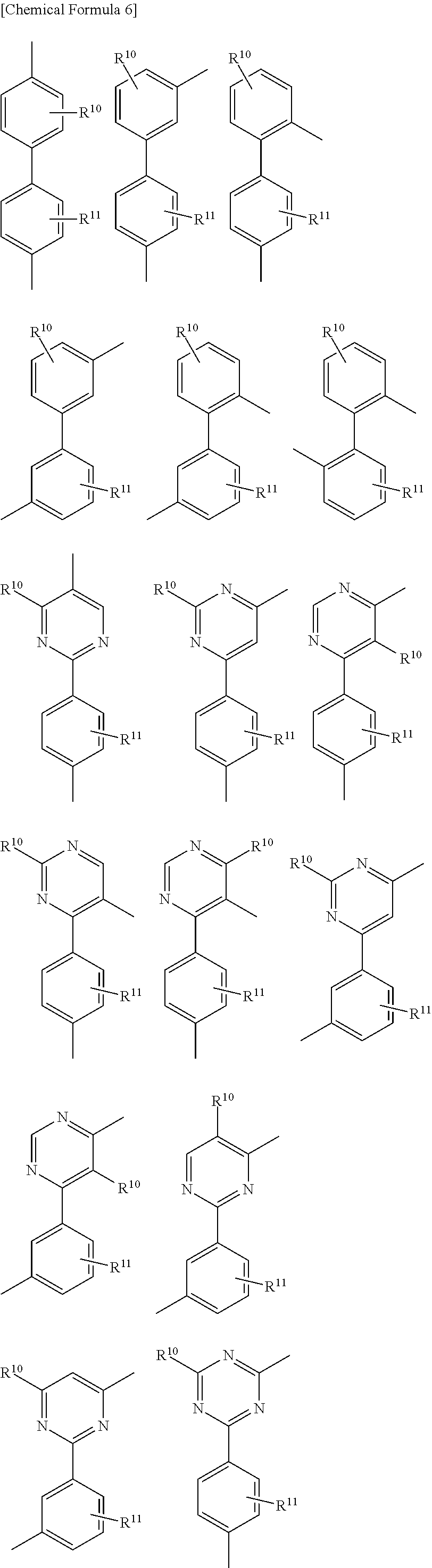


Cz more preferably has any one of the following structures.


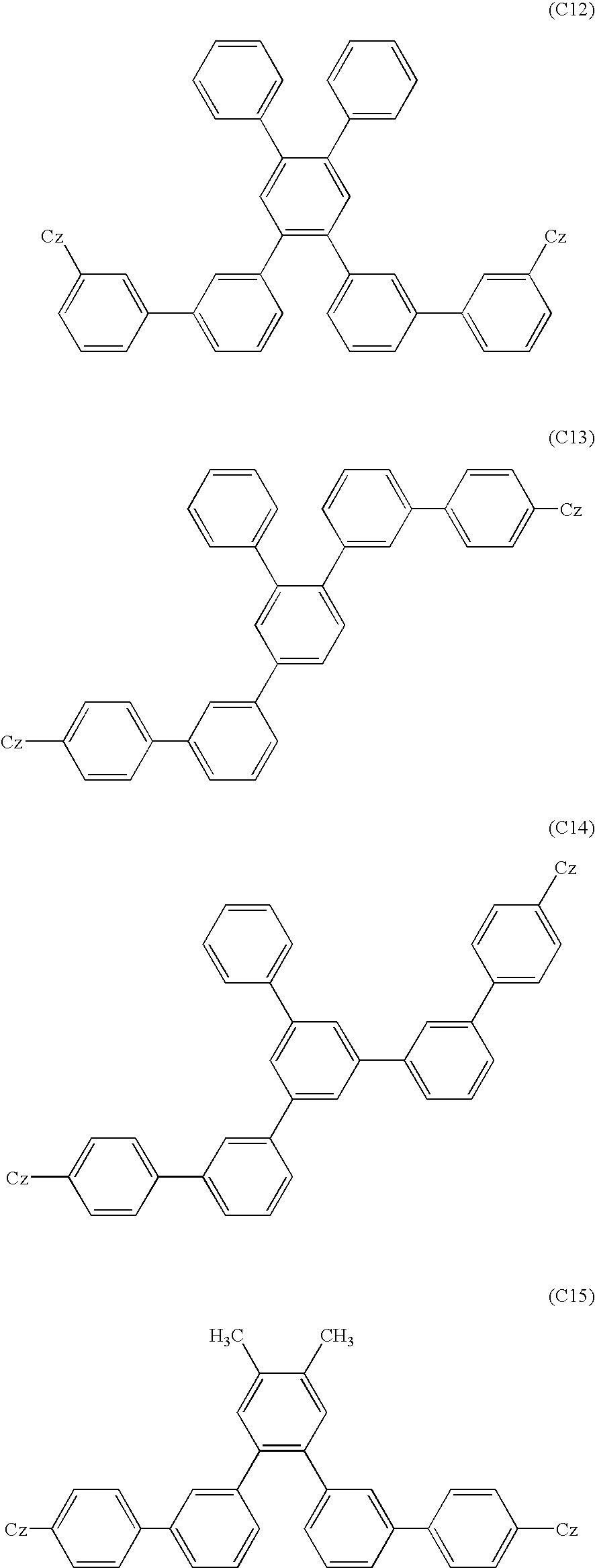


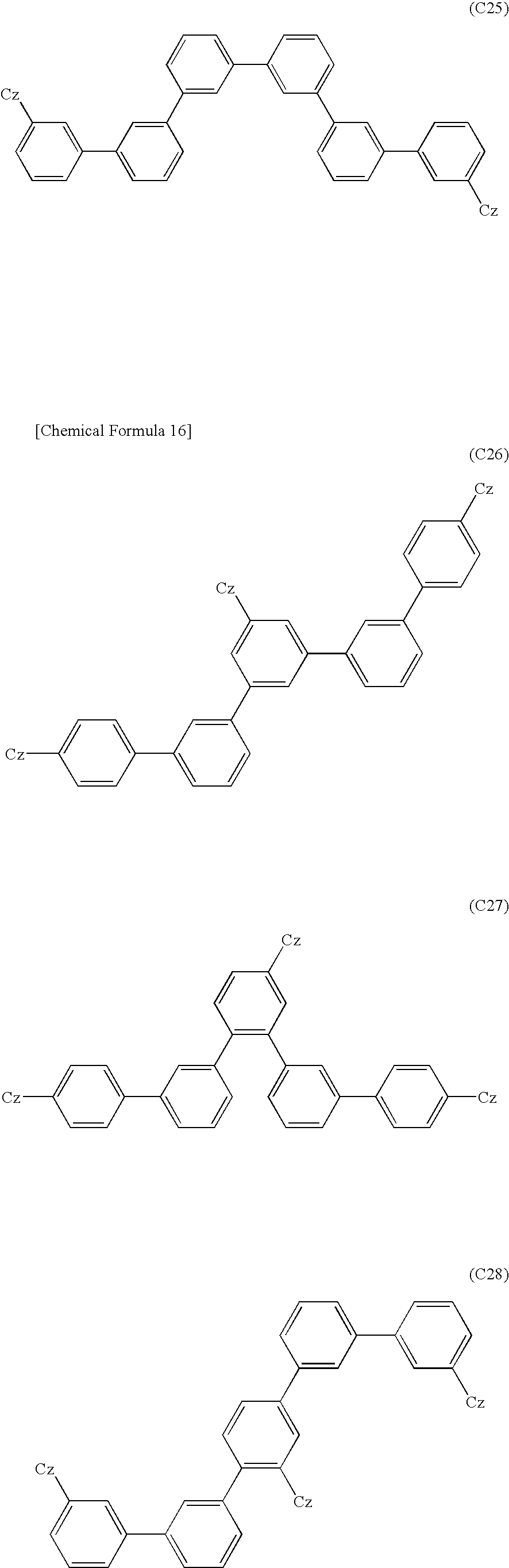


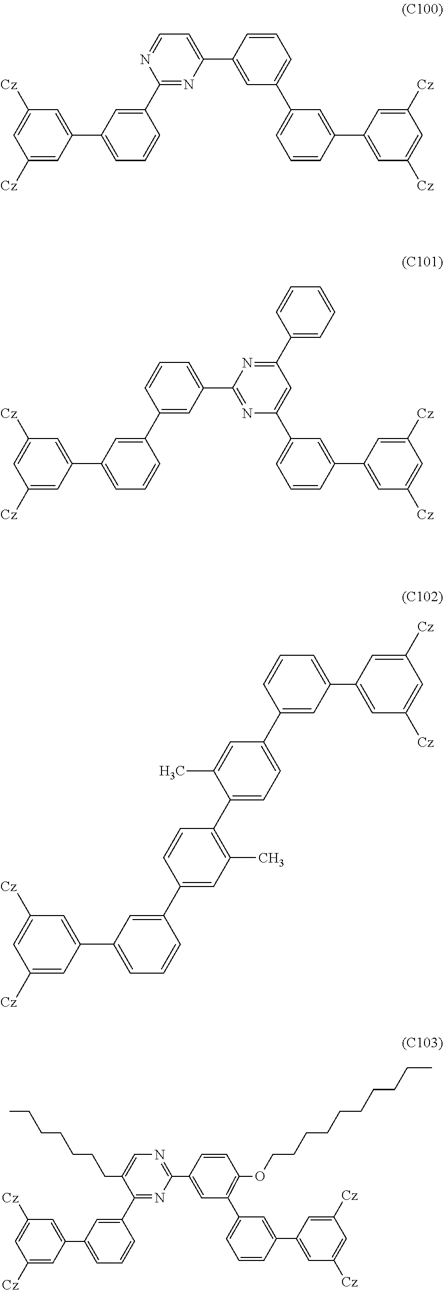


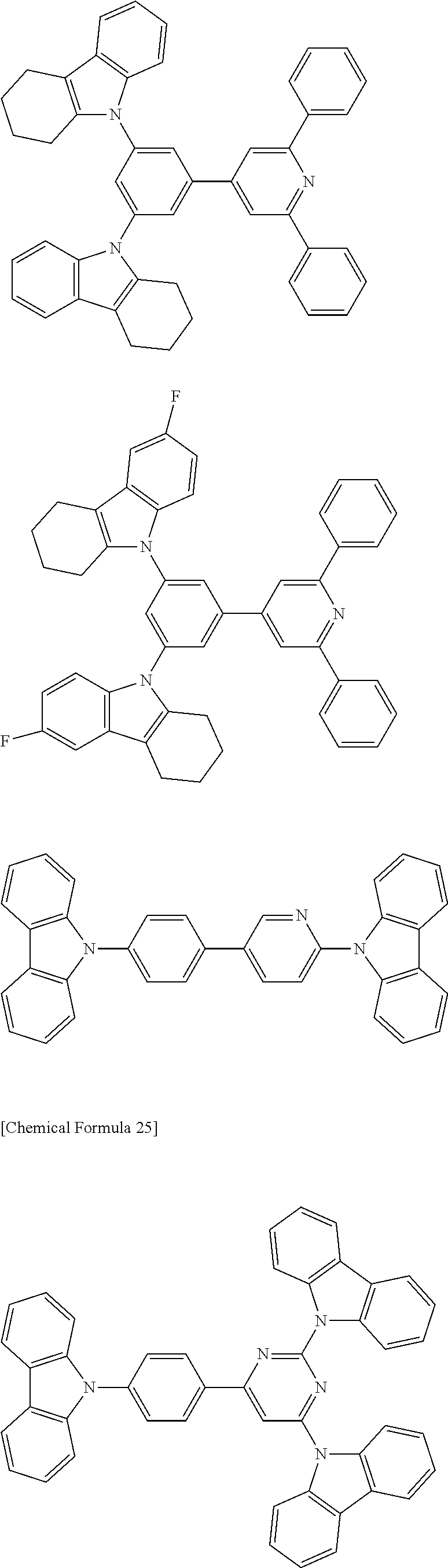


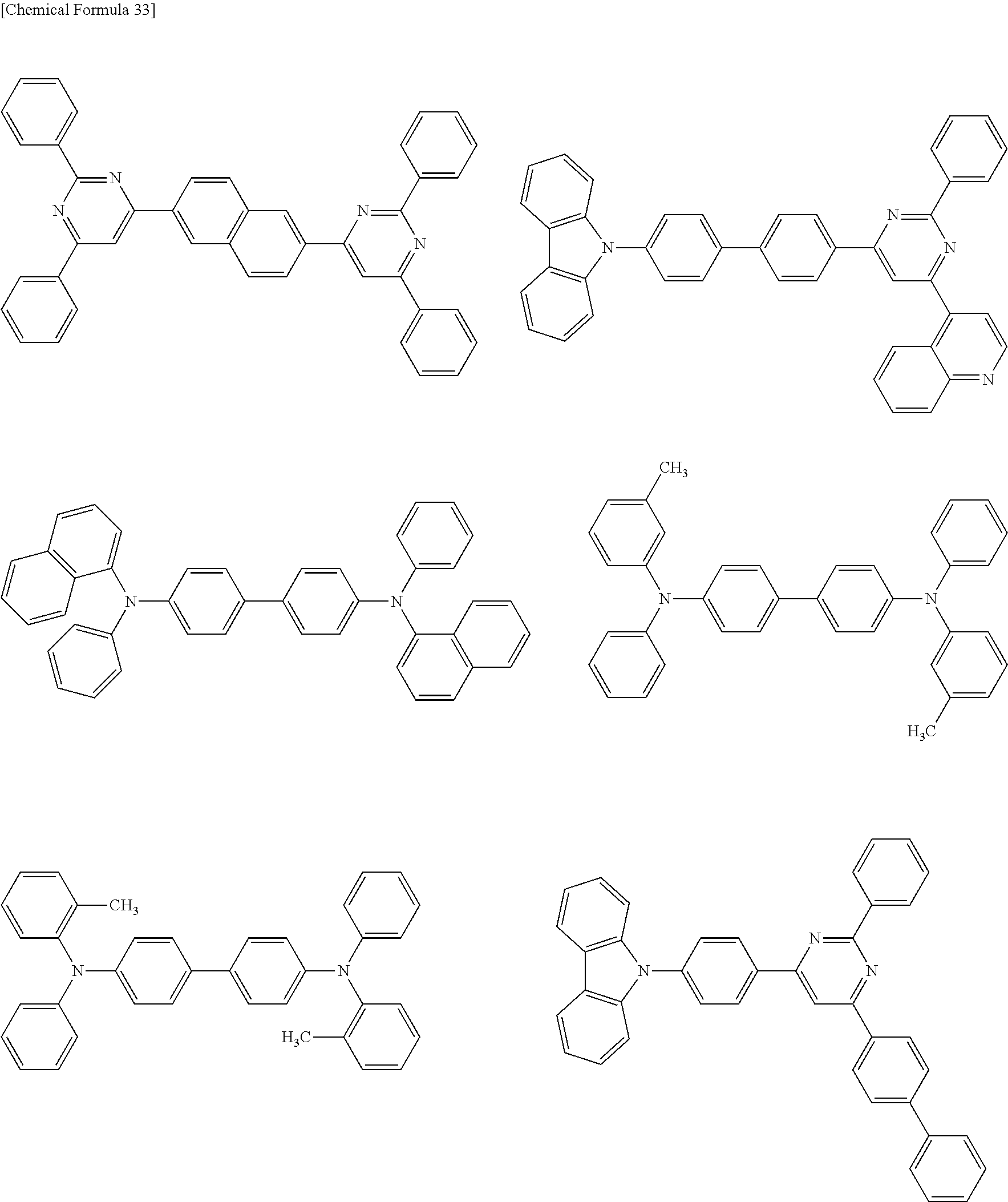


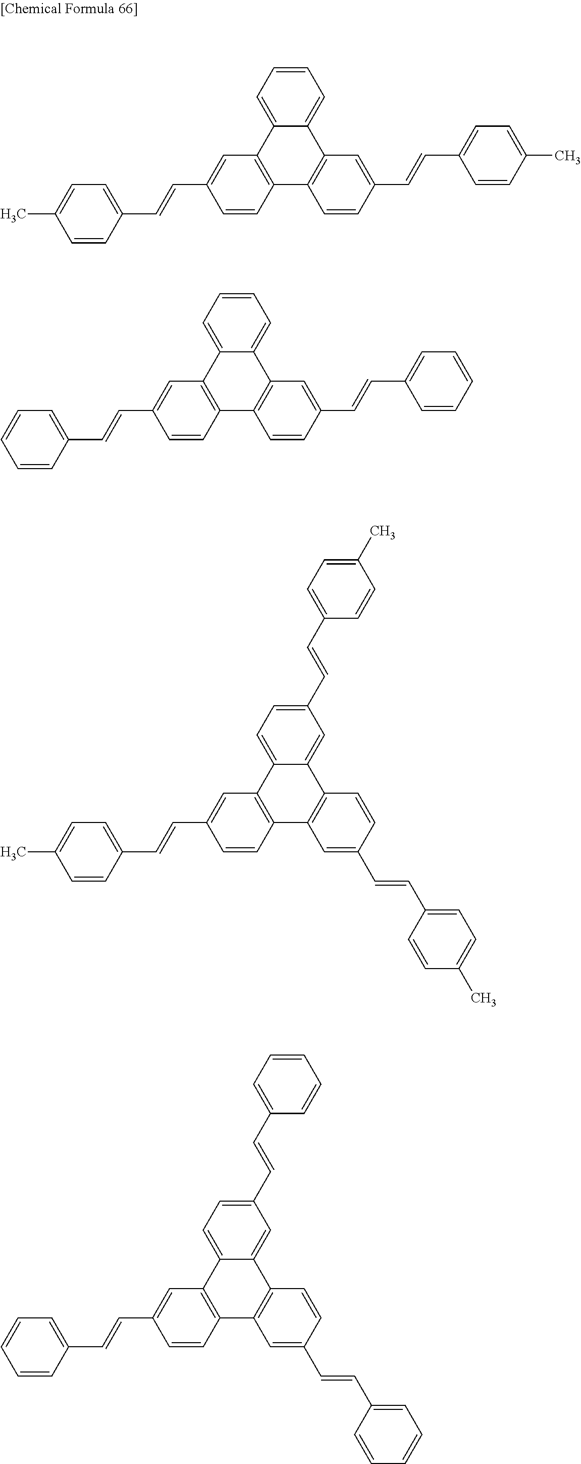


Np—(Np)n—Np (41)


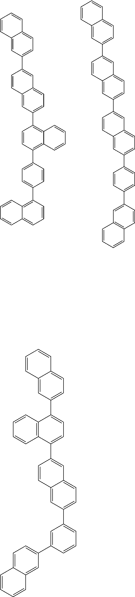


In the formula: n is 1 or 2; Ar1 is a substituent represented by the general formula (57) or (58); Ar2 is a substituent represented by the general formula (59); Ar3 is a substituent represented by the general formula (60) or (61); and R1 to R3 each independently represent a hydrogen atom, linear or branched alkyl group having 6 or less carbon atoms, alicyclic alkyl group, substituted or unsubstituted aromatic ring, substituted or unsubstituted heteroaromatic ring, alkoxy group, amino group, cyano group, silyl group, ester group, carbonyl group or halogen.
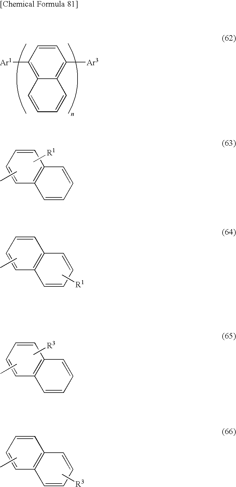
In the formula: n is 1 or 2; Ar1 is a substituent represented by the general formula (63) or (64); Ar3 is a substituent represented by the general formula (65) or (66); and R1 and R3 each independently represent a hydrogen atom, linear or branched alkyl group having 6 or less carbon atoms, alicyclic alkyl group, substituted or unsubstituted aromatic ring, substituted or unsubstituted heteroaromatic ring, alkoxy group, amino group, cyano group, silyl group, ester group, carbonyl group or halogen.

In the formula: n is 1 or 2; Ar1 is a substituent represented by the general formula (68) or (69); Ar3 is a substituent represented by the general formula (70) or (71); and R1 and R3 each independently represent a hydrogen atom, linear or branched alkyl group having 6 or less carbon atoms, alicyclic alkyl group, substituted or unsubstituted aromatic ring, substituted or unsubstituted heteroaromatic ring, alkoxy group, amino group, cyano group, silyl group, ester group, carbonyl group or halogen.

In the formula: n is 1 or 2; Ar1 is a substituent represented by the general formula (73) or (74); Ar3 is a substituent represented by the general formula (75) or (76); and R1 and R3 each independently represent a hydrogen atom, linear or branched alkyl group having 6 or less carbon atoms, alicyclic alkyl group, substituted or unsubstituted aromatic ring, substituted or unsubstituted heteroaromatic ring, alkoxy group, amino group, cyano group, silyl group, ester group, carbonyl group or halogen.

In the formula: n is 1 or 2; Ar1 is a substituent represented by the general formula (78) or (79); Ar3 is a substituent represented by the general formula (80) or (81); and R1 and R3 each independently represent a hydrogen atom, linear or branched alkyl group having 6 or less carbon atoms, alicyclic alkyl group, substituted or unsubstituted aromatic ring, substituted or unsubstituted heteroaromatic ring, alkoxy group, amino group, cyano group, silyl group, ester group, carbonyl group or halogen.


In the formula, R1 to R6 each are an independent group suitably selected from the group consisting of hydrogen, alkoxy group having 1 to 4 carbon atoms, alkyl group having 1 to 4 carbon atoms and substituted or unsubstituted amino group. n is an integer of 2 to 4.


Ra—Ar1—Rb (141)
Ra—Ar1—Ar2—Rb (142)
Ra—Ar1—Ar2—Ar3—Rb (143)


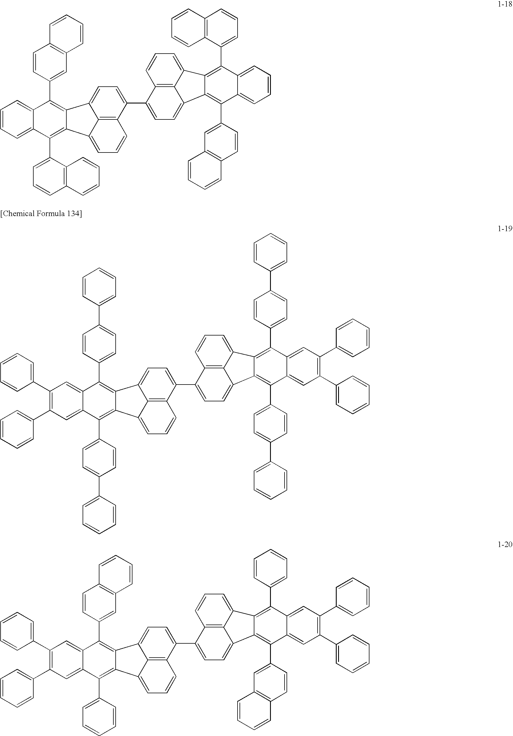


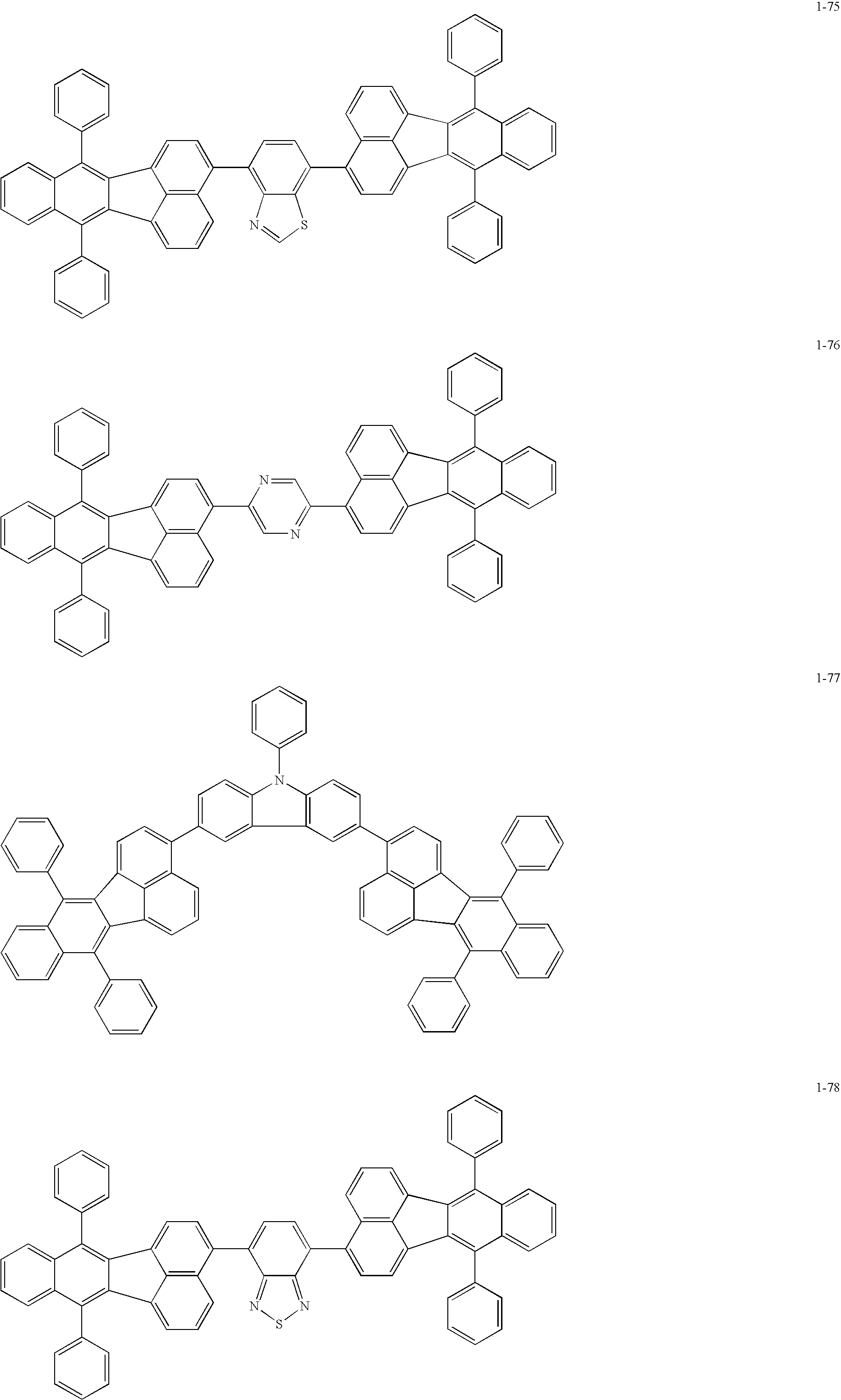


In the formula, Ar17, Ar18, Ar19, Ar21, Ar22 and Ar25 each represent a substituted or unsubstituted arylene group. Ar17, Ar19 and Ar22 may be the same as or different from Ar18, Ar21 and Ar25 respectively. Ar20, Ar23 and Ar24 each represent a substituted or unsubstituted arylene group. Ar23 and Ar24 may be mutually the same or different.


In the formula, X represents a carbon atom or a nitrogen atom. Z1 and Z2 each independently represent an atom group capable of forming a nitrogen-containing heterocycle.


HAr-L1-Ar1—Ar2
In the formula, HAr represents a substituted or unsubstituted nitrogen-containing heterocycle having 3 to 40 carbon atoms; L1 represents a single bond, a substituted or unsubstituted arylene group having 6 to 40 carbon atoms, or a substituted or unsubstituted heteroarylene group having 3 to 40 carbon atoms; Ar1 represents a substituted or unsubstituted divalent aromatic hydrocarbon group having 6 to 40 carbon atoms; and Ar2 represents a substituted or unsubstituted aryl group having 6 to 40 carbon atoms, or a substituted or unsubstituted heteroaryl group having 3 to 40 carbon atoms.


In the formula, R1 to R4 each independently represent a hydrogen atom, a substituted or unsubstituted aliphatic group, a substituted or unsubstituted alicyclic group, a substituted or unsubstituted carbocyclic aromatic ring group, or substituted or unsubstituted heterocyclic group. X1 and X2 each independently represent an oxygen atom, a sulfur atom or a dicyanomethylene group.


In the formula, R5, R6, R7, R8 and R9, which may be mutually the same or different, each represent a hydrogen atom, a saturated or unsaturated alkoxyl group, an alkyl group, an amino group or an alkylamino group. At least one of R5, R6, R7, R8 and R9 represents a saturated or unsaturated alkoxyl group, an alkyl group, an amino group or an alkylamino group.

In the formula, Ar211 to Ar213 and Ar221 to Ar223 each represent a substituted or unsubstituted arylene group having 6 to 50 ring carbon atoms or a substituted or unsubstituted heteroarylene group having 5 to 50 ring atoms. Ar203 to Ar208 each represent a substituted or unsubstituted aryl group having 6 to 50 ring carbon atoms or a substituted or unsubstituted heteroaryl group having 5 to 50 ring atoms. a to c and p to r each represent an integer of 0 to 3. Ar203 and Ar204, Ar205 and Ar206, and Ar207 and Ar208 may be respectively linked together to form saturated or unsaturated rings.

In the formula, Ar231 to Ar234 each represent a substituted or unsubstituted aryl group having 6 to 50 ring carbon atoms or a substituted or unsubstituted heteroaryl group having 5 to 50 ring atoms. L represents a single bond, a substituted or unsubstituted arylene group having 6 to 50 ring carbon atoms or a substituted or unsubstituted heteroarylene group having 5 to 50 ring atoms. x is an integer of 0 to 5.
Ar232 and Ar233 may be linked together to form saturated or unsaturated ring. Examples of the substituted or unsubstituted aryl group and arylene group having 6 to 50 ring carbon atoms, and of the substituted or unsubstituted heteroaryl group and heteroarylene group having 5 to 50 ring atoms are the same as enumerated above.

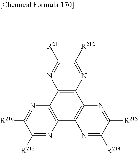
R211 to R216 each represent a substituent, preferably an electron absorbing group such as cyano group, nitro group, sulfonyl group, carbonyl group, trifluoromethyl group and halogen.

Af=Ip−Eg(S)


| TABLE 1 | |||
| Chromaticity | |||
| (CIE color | |||
| EQE | Time until Half-Life | system) | |
| (%) | T50@1000 cd/m2 (h) | x | y | |
| Example 1 | 12.6 | 1000 | 0.459 | 0.220 |
| Example 2 | 12.8 | 1250 | 0.298 | 0.361 |
| Example 3 | 12.2 | 1300 | 0.311 | 0.488 |
| Example 4 | 12.1 | 1000 | 0.441 | 0.394 |
| Example 5 | 14.5 | 1300 | 0.344 | 0.492 |
| Example 6 | 15.5 | 1400 | 0.329 | 0.567 |
| Example 7 | 16.6 | 500 | 0.355 | 0.439 |
| Example 8 | 17.0 | 650 | 0.341 | 0.479 |
| Example 9 | 12.4 | 500 | 0.335 | 0.370 |
| Example 10 | 13.3 | 800 | 0.454 | 0.226 |
| Example 11 | 12.1 | 600 | 0.427 | 0.219 |
| Example 12 | 12.3 | 950 | 0.462 | 0.243 |
| Example 13 | 11.8 | 900 | 0.479 | 0.255 |
| Example 14 | 16.8 | 550 | 0.356 | 0.428 |
| Example 15 | 13.4 | 1300 | 0.296 | 0.366 |
| Example 16 | 17.1 | 350 | 0.368 | 0.445 |
| Example 17 | 16.6 | 500 | 0.352 | 0.402 |
| Example 18 | 16.3 | 400 | 0.377 | 0.398 |
| Example 19 | 12.5 | 1500 | 0.291 | 0.324 |
| Example 20 | 13.9 | 2000 | 0.298 | 0.331 |
| Example 21 | 16.5 | 350 | 0.275 | 0.352 |
| Example 22 | 14.7 | 3000 | 0.342 | 0.398 |
| Example 23 | 13.9 | 2200 | 0.329 | 0.354 |
| Example 24 | 15.1 | 2500 | 0.361 | 0.375 |
| Comparative 1 | 16.7 | 150 | 0.300 | 0.426 |
| Comparative 2 | 5.1 | 300 | 0.311 | 0.341 |
| TABLE 2 | |||||
| Ip | Ea | Eg(S) | Eg(T) | ||
| Material | (eV) | (eV) | (eV) | (eV) | |
| H1 | 5.88 | 2.64 | 3.24 | 2.38 | |
| H2 | 5.98 | 2.41 | 3.57 | 2.89 | |
| H3 | 6.04 | 2.55 | 3.49 | 2.44 | |
| A1 | 6.00 | 2.70 | 3.30 | 2.60 | |
| A2 | 6.10 | 2.80 | 3.30 | 2.60 | |
| A3 | 6.00 | 2.70 | 3.30 | 2.60 | |
| RD | — | — | — | 2.03 | |
| BD | 5.47 | 2.67 | 2.80 | — | |
| BD2 | 5.85 | 2.73 | 3.12 | — | |
| BD3 | 5.38 | 2.59 | 2.79 | — | |
| BD4 | 5.92 | 3.00 | 2.92 | — | |
| GD | 5.50 | 3.00 | 2.50 | — | |
| Ir(ppy)3 | — | — | — | 2.56 | |
| Ir(Ph-ppy)3 | — | — | — | 2.52 | |
| CBP | 6.06 | 2.50 | 3.56 | 2.81 | |
Claims (11)
Applications Claiming Priority (3)
| Application Number | Priority Date | Filing Date | Title |
|---|---|---|---|
| JP2007-179116 | 2007-07-07 | ||
| JP2007179116 | 2007-07-07 | ||
| PCT/JP2008/062137 WO2009008349A1 (en) | 2007-07-07 | 2008-07-04 | Organic el element and organic el material-containing solution |
Publications (2)
| Publication Number | Publication Date |
|---|---|
| US20100270539A1 US20100270539A1 (en) | 2010-10-28 |
| US9082995B2 true US9082995B2 (en) | 2015-07-14 |
Family
ID=40228526
Family Applications (1)
| Application Number | Title | Priority Date | Filing Date |
|---|---|---|---|
| US12/667,893 Active 2030-07-28 US9082995B2 (en) | 2007-07-07 | 2008-07-04 | Organic EL element and organic EL material-containing solution |
Country Status (7)
| Country | Link |
|---|---|
| US (1) | US9082995B2 (en) |
| EP (1) | EP2166590A4 (en) |
| JP (1) | JP5357023B2 (en) |
| KR (1) | KR20100057593A (en) |
| CN (1) | CN101730947A (en) |
| TW (1) | TW200920178A (en) |
| WO (1) | WO2009008349A1 (en) |
Cited By (11)
| Publication number | Priority date | Publication date | Assignee | Title |
|---|---|---|---|---|
| US20150280160A1 (en) * | 2014-03-28 | 2015-10-01 | Lg Display Co., Ltd. | Organic Light Emitting Device |
| US9431615B2 (en) * | 2014-09-19 | 2016-08-30 | Samsung Display Co., Ltd. | Organic light-emitting device emitting delayed fluorescence |
| US9590208B2 (en) | 2012-03-14 | 2017-03-07 | Semiconductor Energy Laboratory Co., Ltd. | Light-emitting element, light-emitting device, electronic device, and lighting device |
| US10361389B2 (en) | 2012-08-03 | 2019-07-23 | Semiconductor Energy Laboratory Co., Ltd. | Light-emitting element, light-emitting device, display device, electronic appliance, and lighting device |
| US10439005B2 (en) | 2013-08-26 | 2019-10-08 | Semiconductor Energy Laboratory Co., Ltd. | Light-emitting element, display module, lighting module, light-emitting device, display device, electronic appliance, and lighting device |
| US10686153B2 (en) | 2014-05-13 | 2020-06-16 | Semiconductor Energy Laboratory Co., Ltd. | Exciplex light-emitting device |
| US10756287B2 (en) | 2009-12-01 | 2020-08-25 | Semiconductor Energy Laboratory Co., Ltd. | Light-emitting element, light-emitting device, electronic device, and lighting device |
| US10903440B2 (en) | 2015-02-24 | 2021-01-26 | Semiconductor Energy Laboratory Co., Ltd. | Light-emitting element, light-emitting device, electronic device, and lighting device |
| US11018313B2 (en) | 2012-08-10 | 2021-05-25 | Semiconductor Energy Laboratory Co., Ltd. | Light-emitting element, light-emitting device, display device, electronic device, and lighting device |
| US11387422B2 (en) | 2014-05-30 | 2022-07-12 | Semiconductor Energy Laboratory Co., Ltd. | Light-emitting element, light-emitting device, electronic device, and lighting device |
| US11495763B2 (en) | 2012-02-09 | 2022-11-08 | Semiconductor Energy Laboratory Co., Ltd. | Light-emitting element |
Families Citing this family (21)
| Publication number | Priority date | Publication date | Assignee | Title |
|---|---|---|---|---|
| JP2009221442A (en) * | 2008-03-19 | 2009-10-01 | Toyo Ink Mfg Co Ltd | Material for organic electroluminescent element and organic electroluminescent element |
| KR20120052231A (en) | 2009-10-16 | 2012-05-23 | 이데미쓰 고산 가부시키가이샤 | Fluorene-containing aromatic compound, material for organic electroluminescent element, and organic electroluminescent element using same |
| JP4637270B1 (en) * | 2010-01-15 | 2011-02-23 | 富士フイルム株式会社 | Organic electroluminescence device |
| JP4644751B1 (en) * | 2010-01-15 | 2011-03-02 | 富士フイルム株式会社 | Organic electroluminescence device |
| KR102004629B1 (en) | 2010-08-20 | 2019-07-26 | 유니버셜 디스플레이 코포레이션 | Bicarbazole compounds for oleds |
| EP2433929B1 (en) | 2010-09-27 | 2013-10-23 | Semiconductor Energy Laboratory Co, Ltd. | Organic Compound, Light-Emitting Element, Light-Emitting Device, Electronic Device, and Lighting Device |
| TWI428312B (en) * | 2010-10-29 | 2014-03-01 | Nat Univ Tsing Hua | 9,10-bisphenylphenanthrene derivative and organic light emitting diode using the same |
| KR101896729B1 (en) | 2010-12-20 | 2018-09-07 | 이데미쓰 고산 가부시키가이샤 | Aromatic heterocycle derivative and organic electroluminescent element using same |
| GB2505834A (en) | 2011-07-04 | 2014-03-12 | Cambridge Display Tech Ltd | Organic light emitting composition, device and method |
| US9209406B2 (en) | 2011-11-22 | 2015-12-08 | Idemitsu Kosan Co., Ltd. | Aromatic heterocyclic derivative, material for organic electroluminescent element, and organic electroluminescent element |
| TWI540779B (en) * | 2012-05-30 | 2016-07-01 | 友達光電股份有限公司 | Organic light-emitting device |
| WO2013182046A1 (en) * | 2012-06-06 | 2013-12-12 | 广东阿格蕾雅光电材料有限公司 | Organic electronic material and organic electroluminescent device |
| US9859517B2 (en) | 2012-09-07 | 2018-01-02 | Nitto Denko Corporation | White organic light-emitting diode |
| JP6113993B2 (en) * | 2012-10-03 | 2017-04-12 | 出光興産株式会社 | Organic electroluminescence device |
| US20140131665A1 (en) * | 2012-11-12 | 2014-05-15 | Universal Display Corporation | Organic Electroluminescent Device With Delayed Fluorescence |
| US10950803B2 (en) * | 2014-10-13 | 2021-03-16 | Universal Display Corporation | Compounds and uses in devices |
| JP6941116B2 (en) * | 2016-11-25 | 2021-09-29 | コニカミノルタ株式会社 | Compositions for organic electroluminescent devices and organic materials |
| WO2018217067A1 (en) * | 2017-05-26 | 2018-11-29 | 삼성에스디아이 주식회사 | Phosphorescent host composition, organic optoelectronic diode, and display device |
| KR102232510B1 (en) * | 2017-05-26 | 2021-03-26 | 삼성에스디아이 주식회사 | Composition for phosphorescent host, organic optoelectronic device and display device |
| KR20180137772A (en) | 2017-06-19 | 2018-12-28 | 삼성에스디아이 주식회사 | Organic optoelectric device and display device |
| KR20210083012A (en) * | 2019-12-26 | 2021-07-06 | 엘지디스플레이 주식회사 | Organic Light Emitting Device and Display Device Using the Same |
Citations (40)
| Publication number | Priority date | Publication date | Assignee | Title |
|---|---|---|---|---|
| JPH09241629A (en) | 1996-03-08 | 1997-09-16 | Idemitsu Kosan Co Ltd | Organic electroluminescent element |
| JP2001250690A (en) | 1999-12-28 | 2001-09-14 | Idemitsu Kosan Co Ltd | White system organic electroluminescence element |
| US20020182441A1 (en) | 2000-08-11 | 2002-12-05 | Trustee Of Princeton University | Organometallic compounds and emission-shifting organic electrophosphorescence |
| JP2003257670A (en) | 2002-02-28 | 2003-09-12 | Eastman Kodak Co | Organic light emitting diode device |
| JP2003317946A (en) | 2002-04-23 | 2003-11-07 | Konica Minolta Holdings Inc | Organic el element and manufacturing method for organic el element |
| WO2004016575A1 (en) | 2002-08-12 | 2004-02-26 | Idemitsu Kosan Co., Ltd. | Oligoarylene derivatives and organic electroluminescent devices made by using the same |
| JP2004506305A (en) | 2000-08-11 | 2004-02-26 | ザ、トラスティーズ オブ プリンストン ユニバーシティ | Organometallic compounds and radiation-transfer organic electrophosphors |
| WO2004018588A1 (en) | 2002-07-19 | 2004-03-04 | Idemitsu Kosan Co., Ltd. | Organic electroluminescent devices and organic luminescent medium |
| US20040124766A1 (en) | 2002-10-24 | 2004-07-01 | Satoshi Nakagawa | Organic electroluminescent device |
| WO2004060026A1 (en) | 2002-12-26 | 2004-07-15 | Semiconductor Energy Laboratory Co., Ltd. | Organic light emitting element |
| JP2004221045A (en) | 2002-11-18 | 2004-08-05 | Idemitsu Kosan Co Ltd | Organic electroluminescent element |
| US20040169461A1 (en) | 2002-06-04 | 2004-09-02 | Takashi Moriyama | Organic light-emitting element and display device |
| JP2005019413A (en) | 2003-06-26 | 2005-01-20 | Eastman Kodak Co | Organic light emitting diode (oled) device |
| US20050073245A1 (en) | 2003-10-06 | 2005-04-07 | Xiong Gong | White electrophosphorescence from semiconducting polymer blends |
| JP2005123205A (en) | 2002-10-24 | 2005-05-12 | Toyota Industries Corp | Organic el element |
| US20050158584A1 (en) * | 1997-12-01 | 2005-07-21 | Thompson Mark E. | OLEDs doped with phosphorescent compounds |
| WO2005079118A1 (en) | 2004-02-13 | 2005-08-25 | Idemitsu Kosan Co., Ltd. | Organic electroluminescent device |
| JP2005235787A (en) | 2005-04-28 | 2005-09-02 | Idemitsu Kosan Co Ltd | Organic electroluminescence element |
| US20050221124A1 (en) * | 2004-04-02 | 2005-10-06 | Seok-Hwan Hwang | Fluorene-based compound and organic electroluminescent display device using the same |
| WO2005117500A1 (en) | 2004-05-27 | 2005-12-08 | Idemitsu Kosan Co., Ltd. | White organic electroluminescent device |
| US20060066225A1 (en) * | 2004-09-29 | 2006-03-30 | Canon Kabushiki Kaisha | Organic electroluminescent device and display apparatus |
| WO2006038020A1 (en) | 2004-10-08 | 2006-04-13 | Cambridge Display Technology Limited | Light emitting device |
| JP2006120689A (en) | 2004-10-19 | 2006-05-11 | Konica Minolta Holdings Inc | Organic electroluminescence element, display device and illumination device |
| JP2006120821A (en) | 2004-10-21 | 2006-05-11 | Konica Minolta Holdings Inc | Organic electroluminescent element, lighting device and indication device |
| WO2006062078A1 (en) | 2004-12-08 | 2006-06-15 | Idemitsu Kosan Co., Ltd. | Organic electroluminescent device |
| JP2006172762A (en) | 2004-12-13 | 2006-06-29 | Toyota Industries Corp | Organic el element |
| JP2006190759A (en) | 2005-01-05 | 2006-07-20 | Idemitsu Kosan Co Ltd | Organic electroluminescent element |
| JP2007019070A (en) | 2005-07-05 | 2007-01-25 | Konica Minolta Holdings Inc | Organic electroluminescent element, liquid crystal display, and light fixture |
| JP2007027620A (en) | 2005-07-21 | 2007-02-01 | Konica Minolta Holdings Inc | Organic electroluminescence element, liquid crystal display and lighting system |
| JP2007059310A (en) | 2005-08-26 | 2007-03-08 | Konica Minolta Holdings Inc | Organic electroluminescence element and lighting system |
| WO2007029426A1 (en) | 2005-09-05 | 2007-03-15 | Idemitsu Kosan Co., Ltd. | Blue light emitting organic electroluminescence element |
| WO2007029806A1 (en) | 2005-09-09 | 2007-03-15 | Idemitsu Kosan Co., Ltd. | Azaaromatic compounds having azafluoranthene skeletons and organic electroluminescent devices made by using the same |
| WO2007032162A1 (en) | 2005-09-16 | 2007-03-22 | Idemitsu Kosan Co., Ltd. | Pyrene derivative and organic electroluminescence device making use of the same |
| JP2007073814A (en) | 2005-09-08 | 2007-03-22 | Idemitsu Kosan Co Ltd | Organic electroluminescence element using polyarylamine |
| JP2007509502A (en) | 2003-10-22 | 2007-04-12 | イーストマン コダック カンパニー | Stabilized white light emitting OLED device |
| US20070120453A1 (en) * | 2005-11-30 | 2007-05-31 | Seok-Hwan Hwang | Full-color electroluminescent display device and method of fabricating the same |
| US20070138947A1 (en) * | 2005-12-21 | 2007-06-21 | Lg.Philips Lcd Co., Ltd. | Organic light emitting devices |
| US20080074034A1 (en) * | 2006-09-22 | 2008-03-27 | Jou Jwo-Huei | Organic Light Emitting Diode Device and Light Emitting Layer Manufacture Method Thereof |
| US20080193773A1 (en) * | 2006-12-29 | 2008-08-14 | Che-Hsiung Hsu | Compositions of electrically conducting polymers made with ultra-pure fully -fluorinated acid polymers |
| US20080213624A1 (en) * | 2007-02-28 | 2008-09-04 | E. I. Du Pont De Nemours And Company | Organic electronic device |
-
2008
- 2008-07-04 JP JP2009522609A patent/JP5357023B2/en active Active
- 2008-07-04 KR KR1020107002487A patent/KR20100057593A/en not_active Application Discontinuation
- 2008-07-04 EP EP08790868A patent/EP2166590A4/en not_active Withdrawn
- 2008-07-04 US US12/667,893 patent/US9082995B2/en active Active
- 2008-07-04 TW TW097125268A patent/TW200920178A/en unknown
- 2008-07-04 WO PCT/JP2008/062137 patent/WO2009008349A1/en active Application Filing
- 2008-07-04 CN CN200880023728.9A patent/CN101730947A/en active Pending
Patent Citations (45)
| Publication number | Priority date | Publication date | Assignee | Title |
|---|---|---|---|---|
| JPH09241629A (en) | 1996-03-08 | 1997-09-16 | Idemitsu Kosan Co Ltd | Organic electroluminescent element |
| US20050158584A1 (en) * | 1997-12-01 | 2005-07-21 | Thompson Mark E. | OLEDs doped with phosphorescent compounds |
| JP2001250690A (en) | 1999-12-28 | 2001-09-14 | Idemitsu Kosan Co Ltd | White system organic electroluminescence element |
| US20020168544A1 (en) | 1999-12-28 | 2002-11-14 | Idemitsu Kosan Co., Ltd. | Organic electroluminescence device emitting white light |
| US20020182441A1 (en) | 2000-08-11 | 2002-12-05 | Trustee Of Princeton University | Organometallic compounds and emission-shifting organic electrophosphorescence |
| JP2004506305A (en) | 2000-08-11 | 2004-02-26 | ザ、トラスティーズ オブ プリンストン ユニバーシティ | Organometallic compounds and radiation-transfer organic electrophosphors |
| JP2003257670A (en) | 2002-02-28 | 2003-09-12 | Eastman Kodak Co | Organic light emitting diode device |
| JP2003317946A (en) | 2002-04-23 | 2003-11-07 | Konica Minolta Holdings Inc | Organic el element and manufacturing method for organic el element |
| US20040169461A1 (en) | 2002-06-04 | 2004-09-02 | Takashi Moriyama | Organic light-emitting element and display device |
| WO2004018588A1 (en) | 2002-07-19 | 2004-03-04 | Idemitsu Kosan Co., Ltd. | Organic electroluminescent devices and organic luminescent medium |
| WO2004016575A1 (en) | 2002-08-12 | 2004-02-26 | Idemitsu Kosan Co., Ltd. | Oligoarylene derivatives and organic electroluminescent devices made by using the same |
| US20070035238A1 (en) | 2002-10-24 | 2007-02-15 | Satoshi Nakagawa | Organic electroluminescent device |
| JP2005123205A (en) | 2002-10-24 | 2005-05-12 | Toyota Industries Corp | Organic el element |
| US20040124766A1 (en) | 2002-10-24 | 2004-07-01 | Satoshi Nakagawa | Organic electroluminescent device |
| JP2004221045A (en) | 2002-11-18 | 2004-08-05 | Idemitsu Kosan Co Ltd | Organic electroluminescent element |
| WO2004060026A1 (en) | 2002-12-26 | 2004-07-15 | Semiconductor Energy Laboratory Co., Ltd. | Organic light emitting element |
| JP2005019413A (en) | 2003-06-26 | 2005-01-20 | Eastman Kodak Co | Organic light emitting diode (oled) device |
| US20050073245A1 (en) | 2003-10-06 | 2005-04-07 | Xiong Gong | White electrophosphorescence from semiconducting polymer blends |
| JP2007509502A (en) | 2003-10-22 | 2007-04-12 | イーストマン コダック カンパニー | Stabilized white light emitting OLED device |
| WO2005079118A1 (en) | 2004-02-13 | 2005-08-25 | Idemitsu Kosan Co., Ltd. | Organic electroluminescent device |
| US20070159083A1 (en) | 2004-02-13 | 2007-07-12 | Idemitsu Kosan Co., Ltd. | Organic electroluminescent device |
| CN1918946A (en) | 2004-02-13 | 2007-02-21 | 出光兴产株式会社 | organic electroluminescent element |
| US20050221124A1 (en) * | 2004-04-02 | 2005-10-06 | Seok-Hwan Hwang | Fluorene-based compound and organic electroluminescent display device using the same |
| WO2005117500A1 (en) | 2004-05-27 | 2005-12-08 | Idemitsu Kosan Co., Ltd. | White organic electroluminescent device |
| US20060066225A1 (en) * | 2004-09-29 | 2006-03-30 | Canon Kabushiki Kaisha | Organic electroluminescent device and display apparatus |
| WO2006038020A1 (en) | 2004-10-08 | 2006-04-13 | Cambridge Display Technology Limited | Light emitting device |
| JP2006120689A (en) | 2004-10-19 | 2006-05-11 | Konica Minolta Holdings Inc | Organic electroluminescence element, display device and illumination device |
| JP2006120821A (en) | 2004-10-21 | 2006-05-11 | Konica Minolta Holdings Inc | Organic electroluminescent element, lighting device and indication device |
| WO2006062078A1 (en) | 2004-12-08 | 2006-06-15 | Idemitsu Kosan Co., Ltd. | Organic electroluminescent device |
| JP2006172762A (en) | 2004-12-13 | 2006-06-29 | Toyota Industries Corp | Organic el element |
| JP2006190759A (en) | 2005-01-05 | 2006-07-20 | Idemitsu Kosan Co Ltd | Organic electroluminescent element |
| JP2005235787A (en) | 2005-04-28 | 2005-09-02 | Idemitsu Kosan Co Ltd | Organic electroluminescence element |
| JP2007019070A (en) | 2005-07-05 | 2007-01-25 | Konica Minolta Holdings Inc | Organic electroluminescent element, liquid crystal display, and light fixture |
| JP2007027620A (en) | 2005-07-21 | 2007-02-01 | Konica Minolta Holdings Inc | Organic electroluminescence element, liquid crystal display and lighting system |
| JP2007059310A (en) | 2005-08-26 | 2007-03-08 | Konica Minolta Holdings Inc | Organic electroluminescence element and lighting system |
| WO2007029426A1 (en) | 2005-09-05 | 2007-03-15 | Idemitsu Kosan Co., Ltd. | Blue light emitting organic electroluminescence element |
| JP2007073814A (en) | 2005-09-08 | 2007-03-22 | Idemitsu Kosan Co Ltd | Organic electroluminescence element using polyarylamine |
| WO2007029806A1 (en) | 2005-09-09 | 2007-03-15 | Idemitsu Kosan Co., Ltd. | Azaaromatic compounds having azafluoranthene skeletons and organic electroluminescent devices made by using the same |
| WO2007032162A1 (en) | 2005-09-16 | 2007-03-22 | Idemitsu Kosan Co., Ltd. | Pyrene derivative and organic electroluminescence device making use of the same |
| US20070120453A1 (en) * | 2005-11-30 | 2007-05-31 | Seok-Hwan Hwang | Full-color electroluminescent display device and method of fabricating the same |
| US20070138947A1 (en) * | 2005-12-21 | 2007-06-21 | Lg.Philips Lcd Co., Ltd. | Organic light emitting devices |
| JP2007173827A (en) | 2005-12-21 | 2007-07-05 | Lg Phillips Lcd Co Ltd | Organic light emitting device |
| US20080074034A1 (en) * | 2006-09-22 | 2008-03-27 | Jou Jwo-Huei | Organic Light Emitting Diode Device and Light Emitting Layer Manufacture Method Thereof |
| US20080193773A1 (en) * | 2006-12-29 | 2008-08-14 | Che-Hsiung Hsu | Compositions of electrically conducting polymers made with ultra-pure fully -fluorinated acid polymers |
| US20080213624A1 (en) * | 2007-02-28 | 2008-09-04 | E. I. Du Pont De Nemours And Company | Organic electronic device |
Non-Patent Citations (10)
| Title |
|---|
| Extended European Search Report issued Mar. 6, 2012, in European Patent Application No. 08790868.7. |
| Gang Cheng, et al., "Improved efficiency for white organic light-emitting devices based on phosphor sensitized fluorescence", Applied Physics Letters, vol. 88, No. 8, XP-012083026, Feb. 24, 2006, pp. 83512-1 to 83512-3. |
| Hiroshi Kanno, et al., "White Organic light-emitting device based on a compound fluorescent-phosphor-sensitized-fluorescent emission layer", Applied Physics Letters, vol. 89, No. 14, Oct. 5, 2006, pp. 143516-1 to 143516-3. |
| Office Action issued Dec. 15, 2010 in China Application No. 200880023728.9 (With English Translation). |
| Shizuo Tokito, et al., "Confinement of triplet energy on phosphorescent molecules for highly-efficient organic blue-light-emitting devices", Applied Physics Letters, vol. 83, No. 3, XP-012035549, Jul. 21, 2003, pp. 569-571. |
| Sun, Y., et al., "Management of Singlet and Triplet Excitons for Efficient White Organic Light-emitting Devices", Nature, vol. 440, pp. 908-912 (2006). |
| U.S. Appl. No. 12/667,939, filed Jan. 6, 2010, Nishimura, et al. |
| U.S. Appl. No. 12/668,035, filed Jan. 7, 2010, Nishimura, et al. |
| U.S. Appl. No. 12/668,110, filed Jan. 7, 2010, Nishimura, et al. |
| U.S. Appl. No. 12/668,111, filed Jan. 7, 2010, Nishimura, et al. |
Cited By (23)
| Publication number | Priority date | Publication date | Assignee | Title |
|---|---|---|---|---|
| US10756287B2 (en) | 2009-12-01 | 2020-08-25 | Semiconductor Energy Laboratory Co., Ltd. | Light-emitting element, light-emitting device, electronic device, and lighting device |
| US11997860B2 (en) | 2012-02-09 | 2024-05-28 | Semiconductor Energy Laboratory Co., Ltd. | Light-emitting element |
| US11495763B2 (en) | 2012-02-09 | 2022-11-08 | Semiconductor Energy Laboratory Co., Ltd. | Light-emitting element |
| US10062867B2 (en) | 2012-03-14 | 2018-08-28 | Semiconductor Energy Laboratory Co., Ltd. | Light-emitting element, light-emitting device, electronic device, and lighting device |
| US9590208B2 (en) | 2012-03-14 | 2017-03-07 | Semiconductor Energy Laboratory Co., Ltd. | Light-emitting element, light-emitting device, electronic device, and lighting device |
| US10361389B2 (en) | 2012-08-03 | 2019-07-23 | Semiconductor Energy Laboratory Co., Ltd. | Light-emitting element, light-emitting device, display device, electronic appliance, and lighting device |
| US10862059B2 (en) | 2012-08-03 | 2020-12-08 | Semiconductor Energy Laboratory Co., Ltd. | Light-emitting element, light-emitting device, display device, electronic appliance, and lighting device |
| US11937439B2 (en) | 2012-08-03 | 2024-03-19 | Semiconductor Energy Laboratory Co., Ltd. | Light-emitting element, light-emitting device, display device, electronic appliance, and lighting device |
| US11322709B2 (en) | 2012-08-03 | 2022-05-03 | Semiconductor Energy Laboratory Co., Ltd. | Light-emitting element, light-emitting device, display device, electronic appliance, and lighting device |
| US11018313B2 (en) | 2012-08-10 | 2021-05-25 | Semiconductor Energy Laboratory Co., Ltd. | Light-emitting element, light-emitting device, display device, electronic device, and lighting device |
| US11690239B2 (en) | 2012-08-10 | 2023-06-27 | Semiconductor Energy Laboratory Co., Ltd. | Light-emitting element, light-emitting device, display device, electronic device, and lighting device |
| US10439005B2 (en) | 2013-08-26 | 2019-10-08 | Semiconductor Energy Laboratory Co., Ltd. | Light-emitting element, display module, lighting module, light-emitting device, display device, electronic appliance, and lighting device |
| US11825718B2 (en) | 2013-08-26 | 2023-11-21 | Semiconductor Energy Laboratory Co., Ltd. | Light-emitting element, display module, lighting module, light-emitting device, display device, electronic appliance, and lighting device |
| US11049908B2 (en) | 2013-08-26 | 2021-06-29 | Semiconductor Energy Laboratory Co., Ltd. | Light-emitting element, display module, lighting module, light-emitting device, display device, electronic appliance, and lighting device |
| US9570701B2 (en) * | 2014-03-28 | 2017-02-14 | Lg Display Co., Ltd. | Organic light emitting device |
| US20150280160A1 (en) * | 2014-03-28 | 2015-10-01 | Lg Display Co., Ltd. | Organic Light Emitting Device |
| US10686153B2 (en) | 2014-05-13 | 2020-06-16 | Semiconductor Energy Laboratory Co., Ltd. | Exciplex light-emitting device |
| US11158832B2 (en) | 2014-05-13 | 2021-10-26 | Semiconductor Energy Laboratory Co., Ltd. | Light-emitting device with exciplex light-emitting layers |
| US11864403B2 (en) | 2014-05-13 | 2024-01-02 | Semiconductor Energy Laboratory Co., Ltd. | Light-emitting device comprising first to third light-emitting layers |
| US11387422B2 (en) | 2014-05-30 | 2022-07-12 | Semiconductor Energy Laboratory Co., Ltd. | Light-emitting element, light-emitting device, electronic device, and lighting device |
| US11832465B2 (en) | 2014-05-30 | 2023-11-28 | Semiconductor Energy Laboratory Co., Ltd. | Light-emitting element, light-emitting device, electronic device, and lighting device |
| US9431615B2 (en) * | 2014-09-19 | 2016-08-30 | Samsung Display Co., Ltd. | Organic light-emitting device emitting delayed fluorescence |
| US10903440B2 (en) | 2015-02-24 | 2021-01-26 | Semiconductor Energy Laboratory Co., Ltd. | Light-emitting element, light-emitting device, electronic device, and lighting device |
Also Published As
| Publication number | Publication date |
|---|---|
| EP2166590A1 (en) | 2010-03-24 |
| EP2166590A4 (en) | 2012-04-04 |
| CN101730947A (en) | 2010-06-09 |
| TW200920178A (en) | 2009-05-01 |
| JP5357023B2 (en) | 2013-12-04 |
| US20100270539A1 (en) | 2010-10-28 |
| WO2009008349A1 (en) | 2009-01-15 |
| JPWO2009008349A1 (en) | 2010-09-09 |
| KR20100057593A (en) | 2010-05-31 |
Similar Documents
| Publication | Publication Date | Title |
|---|---|---|
| US9082995B2 (en) | Organic EL element and organic EL material-containing solution | |
| US8436343B2 (en) | Organic EL device | |
| US8294142B2 (en) | Organic EL device | |
| US10079343B2 (en) | Organic el element and solution containing organic el material | |
| US8426036B2 (en) | Organic EL device and anthracene derivative | |
| US20100171109A1 (en) | Organic el device | |
| US8207526B2 (en) | Organic EL device | |
| US8211552B2 (en) | Organic electroluminescence device | |
| US9324950B2 (en) | Organic electroluminescence device | |
| US9112171B2 (en) | Organic light emitting device and materials for use in same | |
| US8883323B2 (en) | Organic electroluminescence device | |
| JP5480364B2 (en) | Organic electroluminescence device | |
| US8154195B2 (en) | Organic electroluminescence device and material for organic electroluminescence device | |
| EP2166586A1 (en) | Organic electroluminescent device | |
| US20120126205A1 (en) | Organic electroluminescence device | |
| US20090045731A1 (en) | Organic electroluminescence device and material for organic electroluminescence device | |
| EP2418707B1 (en) | Organic electroluminescent element and material for organic electroluminescent element | |
| US8039129B2 (en) | Organic electroluminescence device and material for organic electroluminescence device | |
| US20130306957A1 (en) | Organic electroluminescent element |
Legal Events
| Date | Code | Title | Description |
|---|---|---|---|
| AS | Assignment |
Owner name: IDEMITSU KOSAN CO., LTD., JAPAN Free format text: ASSIGNMENT OF ASSIGNORS INTEREST;ASSIGNORS:NISHIMURA, KAZUKI;HOSOKAWA, CHISHIO;IWAKUMA, TOSHIHIRO;AND OTHERS;REEL/FRAME:023767/0798 Effective date: 20091225 |
|
| STCF | Information on status: patent grant |
Free format text: PATENTED CASE |
|
| FEPP | Fee payment procedure |
Free format text: PAYOR NUMBER ASSIGNED (ORIGINAL EVENT CODE: ASPN); ENTITY STATUS OF PATENT OWNER: LARGE ENTITY |
|
| MAFP | Maintenance fee payment |
Free format text: PAYMENT OF MAINTENANCE FEE, 4TH YEAR, LARGE ENTITY (ORIGINAL EVENT CODE: M1551); ENTITY STATUS OF PATENT OWNER: LARGE ENTITY Year of fee payment: 4 |
|
| MAFP | Maintenance fee payment |
Free format text: PAYMENT OF MAINTENANCE FEE, 8TH YEAR, LARGE ENTITY (ORIGINAL EVENT CODE: M1552); ENTITY STATUS OF PATENT OWNER: LARGE ENTITY Year of fee payment: 8 |