US9076563B2 - Anti-scatter collimators for detector systems of multi-slice X-ray computed tomography systems - Google Patents
Anti-scatter collimators for detector systems of multi-slice X-ray computed tomography systems Download PDFInfo
- Publication number
- US9076563B2 US9076563B2 US13/908,897 US201313908897A US9076563B2 US 9076563 B2 US9076563 B2 US 9076563B2 US 201313908897 A US201313908897 A US 201313908897A US 9076563 B2 US9076563 B2 US 9076563B2
- Authority
- US
- United States
- Prior art keywords
- detector
- ray
- axis
- scatter
- detector modules
- Prior art date
- Legal status (The legal status is an assumption and is not a legal conclusion. Google has not performed a legal analysis and makes no representation as to the accuracy of the status listed.)
- Active - Reinstated, expires
Links
- 238000002591 computed tomography Methods 0.000 title claims abstract description 61
- 239000011159 matrix material Substances 0.000 claims abstract description 13
- 230000005855 radiation Effects 0.000 claims abstract description 6
- 230000003247 decreasing effect Effects 0.000 claims description 2
- 239000011295 pitch Substances 0.000 description 11
- 239000000463 material Substances 0.000 description 5
- 238000004519 manufacturing process Methods 0.000 description 4
- 230000002238 attenuated effect Effects 0.000 description 3
- 238000003384 imaging method Methods 0.000 description 3
- 238000010521 absorption reaction Methods 0.000 description 2
- QWUZMTJBRUASOW-UHFFFAOYSA-N cadmium tellanylidenezinc Chemical compound [Zn].[Cd].[Te] QWUZMTJBRUASOW-UHFFFAOYSA-N 0.000 description 2
- 238000006243 chemical reaction Methods 0.000 description 2
- 238000010586 diagram Methods 0.000 description 2
- 230000003993 interaction Effects 0.000 description 2
- 230000000903 blocking effect Effects 0.000 description 1
- 238000001514 detection method Methods 0.000 description 1
- 238000003745 diagnosis Methods 0.000 description 1
- 238000005259 measurement Methods 0.000 description 1
- 239000000203 mixture Substances 0.000 description 1
- 230000035945 sensitivity Effects 0.000 description 1
Images


Classifications
-
- G—PHYSICS
- G21—NUCLEAR PHYSICS; NUCLEAR ENGINEERING
- G21K—TECHNIQUES FOR HANDLING PARTICLES OR IONISING RADIATION NOT OTHERWISE PROVIDED FOR; IRRADIATION DEVICES; GAMMA RAY OR X-RAY MICROSCOPES
- G21K1/00—Arrangements for handling particles or ionising radiation, e.g. focusing or moderating
- G21K1/02—Arrangements for handling particles or ionising radiation, e.g. focusing or moderating using diaphragms, collimators
- G21K1/025—Arrangements for handling particles or ionising radiation, e.g. focusing or moderating using diaphragms, collimators using multiple collimators, e.g. Bucky screens; other devices for eliminating undesired or dispersed radiation
-
- A—HUMAN NECESSITIES
- A61—MEDICAL OR VETERINARY SCIENCE; HYGIENE
- A61B—DIAGNOSIS; SURGERY; IDENTIFICATION
- A61B6/00—Apparatus or devices for radiation diagnosis; Apparatus or devices for radiation diagnosis combined with radiation therapy equipment
- A61B6/02—Arrangements for diagnosis sequentially in different planes; Stereoscopic radiation diagnosis
- A61B6/03—Computed tomography [CT]
- A61B6/032—Transmission computed tomography [CT]
-
- A—HUMAN NECESSITIES
- A61—MEDICAL OR VETERINARY SCIENCE; HYGIENE
- A61B—DIAGNOSIS; SURGERY; IDENTIFICATION
- A61B6/00—Apparatus or devices for radiation diagnosis; Apparatus or devices for radiation diagnosis combined with radiation therapy equipment
- A61B6/42—Arrangements for detecting radiation specially adapted for radiation diagnosis
- A61B6/4291—Arrangements for detecting radiation specially adapted for radiation diagnosis the detector being combined with a grid or grating
-
- G—PHYSICS
- G01—MEASURING; TESTING
- G01T—MEASUREMENT OF NUCLEAR OR X-RADIATION
- G01T1/00—Measuring X-radiation, gamma radiation, corpuscular radiation, or cosmic radiation
- G01T1/16—Measuring radiation intensity
- G01T1/161—Applications in the field of nuclear medicine, e.g. in vivo counting
- G01T1/164—Scintigraphy
- G01T1/1641—Static instruments for imaging the distribution of radioactivity in one or two dimensions using one or several scintillating elements; Radio-isotope cameras
- G01T1/1648—Ancillary equipment for scintillation cameras, e.g. reference markers, devices for removing motion artifacts, calibration devices
Definitions
- the present disclosure relates to multi-slice X-ray Computed Tomography (CT) systems.
- X-rays are used to image internal structures and features of a region of a subject or an object.
- subject and “object” shall include anything capable of being imaged.
- the imaging is performed by an X-ray CT system, which images internal structures and features of a plurality of thin planar slices or a 3D volume of a region of an object using X-rays.
- the imaging objects include human bodies.
- An X-ray CT system generally comprises an X-ray source that provides a cone-shaped X-ray beam and an array of closely spaced X-ray detectors that face the X-ray source.
- the X-ray source and the array of detectors are mounted in a gantry so that a patient being imaged with the CT system, generally lying on an appropriate support couch, can be positioned within the gantry between the X-ray source and the array of detectors.
- the gantry and the couch are moveable relative to each other so that the X-ray source and the detector array can be positioned axially at desired locations along the patient's body.
- the gantry comprises a stationary structure referred to as a stator and a rotary element referred to as a rotor, which is mounted to the stator so that the rotor is rotatable about the axial direction.
- the X-ray source and the array of detectors are mounted on the rotor.
- Angular positions of the rotor about the axial direction are controllable so that the X-ray source can be positioned at desired angles, referred to as view angles, around a patient's body.
- the X-ray source is positioned at an axial position of the slice and the X-ray source is rotated around the slice to illuminate the slice with X-rays from a plurality of different view angles.
- detectors in the array of detectors generate signals responsive to the intensity of X-rays from the source that pass through the slice.
- the signals are processed to determine the amounts, by which X-rays from the X-ray source are attenuated over various path lengths through the slice that the X-rays traverse, in passing though the slice from the X-ray source to the detectors.
- the amounts, by which the X-rays are attenuated, are used to determine the X-ray absorption coefficients of materials in the slice as a function of position in the slice.
- the absorption coefficients are used to generate an image of the slice and identify compositions and densities of tissues in the slice.
- the X-ray detectors comprised in a detector array of CT system are generally packaged in a plurality of modules, hereinafter referred to as detector modules, each of which comprises a plurality of X-ray detector elements.
- detector modules each of which comprises a plurality of X-ray detector elements.
- Most modern CT systems are multi-slice CT systems designed to simultaneously image a plurality of slices of a patient.
- the X-ray detector elements in each detector module of a multi-slice CT scanner are arranged in a matrix of rows and columns.
- the X-ray detector matrices of any two CT detector modules in a CT system are substantially identical and comprise a same number of rows of detector elements and a same number of columns of detector elements.
- the modules are positioned one adjacent to and contiguous with the other in a closely packed array with their rows of detectors aligned end to end so that the X-ray detector elements form a plurality of long parallel rows of X-ray detector elements.
- a multi-slice X-ray CT system is usually named or featured by the maximum number of slices that it can simultaneously image, for example, an 8-slice CT system means that it can simultaneously image at most 8 slices; a 16-slice CT system can simultaneously image at most 16 slices.
- the X-ray detector elements in each long row of the detector array lie on an arc of a circle having its center located at a focal point of the CT system's X-ray source, and the design of these detector elements and the detector modules is specifically determined by the radius of the circle, which is hereinafter referred to as focusing distance.
- the design of X-ray detector modules placed on the arc of one focusing distance of one CT system cannot therefore be used on another CT system of a different focusing distance.
- Each detector element in a scintillator array is comprised of a finite active area for detecting X-ray photons and generating second-energy photons or electric charges when using X-ray direct conversion materials. Detector elements are surrounded by non-active areas, referred hereafter as gaps, which do not generate responses for X-ray photons.
- An X-ray detector array typically includes an anti-scatter collimator having a plurality of anti-scatter plates for collimating x-ray beams received at each detector element: a scintillator for converting x-rays to light energy adjacent to the collimator, and a photodiode for receiving the light energy from the coupled scintillator and producing electric charges therefrom.
- the anti-scatter plates of the collimator are placed at the locations of the gaps of the detector modules to very tight and exact tolerances. This alignment of the detector modules with the anti-scatter plates of the collimator can be very costly for manufacturing because of required very tight and exact tolerances.
- a detector system for a multi-slice X-ray Computed Tomography (CT) system comprises at least one X-ray source, comprises: a plurality of X-ray detector modules for detecting X-ray photons; wherein each of the detector modules is divided into individual detector elements organized in a matrix fashion with element rows (z-axis for row direction) and element columns (x-axis for column direction) for detecting X-ray photons; wherein the individual detector elements are interspaced by gaps (areas that do not detect radiation), which are also organized in a matrix fashion with gap rows and gap columns; and an anti-scatter collimator comprising a plurality of anti-scatter plates placed above the detector modules and aligned to focus on the X-ray source; wherein some or all of the anti-scatter plates are placed above the detector elements; wherein those anti-scatter plates that are placed above the detector elements block
- the anti-scatter plates parallel with the z-axis may be placed above some or all element columns of the detector modules but not above any gap columns of the detector modules; the anti-scatter plates parallel with the z-axis may not be placed between any of two detector modules next to each other along the x-axis.
- the anti-scatter plates parallel with the z-axis may be placed above some or all element columns of the detector modules but not above any middle gap columns of the detector modules; wherein the anti-scatter plates parallel with the z-axis may also be placed between any of two detector modules next to each other along the x-axis.
- the edge element column width of the detector modules may be smaller than the middle element column width of the detector modules.
- the nominal value of the thickness of the anti-scatter plates may equal to the difference between the edge element column width and the middle element column width of the detector modules.
- CT Computed Tomography
- the detector system comprises: a plurality of X-ray detector modules for detecting X-ray photons; wherein each detector module is divided into individual detector elements organized in a matrix fashion with element rows (z-axis for row direction) and element columns (x-axis for column direction) for detecting X-ray photons; wherein individual detector elements are interspaced by gaps (areas that do not detect radiation), which are also organized in matrix fashion with gap rows and gap columns; and an anti-scatter collimator comprising a plurality of anti-scatter plates, which is placed above the detector modules and aligned to focus on the X-ray source; wherein some or all of the anti-scatter plates are placed above the detector elements; wherein those anti-scatter plates that are placed above the detector elements block a portion of primary X-ray photons from the X-ray source in addition to scattered X-ray photons from reaching the detector elements.
- FIG. 1 illustrates a schematic functional diagram of a prior art multi-slice X-ray CT system.
- FIG. 2A illustrates prior art detector modules placed side by side to form a CT detector system.
- FIG. 2B illustrates a prior art arrangement of anti-scatter plates and detector modules of a CT detector system.
- FIG. 2C shows a cross-sectional view illustrating a prior art arrangement of anti-scatter plates and detector modules of a CT detector system.
- FIG. 3A illustrates an arrangement of anti-scatter plates of an anti-scatter collimator and detector modules of a CT detector system in accordance with one embodiment of the present disclosure.
- FIG. 3B shows a cross-sectional view illustrating an arrangement of anti-scatter plates of an anti-scatter collimator and detector modules of a CT detector system in accordance with one embodiment of the present disclosure.
- FIG. 4A illustrates an arrangement of anti-scatter plates of an anti-scatter collimator and detector modules of a CT detector system in accordance with one embodiment of the present disclosure.
- FIG. 4B shows a cross-sectional view illustrating an arrangement of anti-scatter plates of an anti-scatter collimator and detector modules of a CT detector system in accordance with one embodiment of the present disclosure.
- FIG. 1 shows a schematic functional diagram of a prior art multi-slice X-ray CT system 100 .
- a multi-slice CT system typically comprises an X-ray source 110 , which generates a cone-shaped X-ray beam 140 .
- the X-ray beam 140 passes through a pre-patient collimator 130 , which allows X-ray beam to illuminate only the targeted area and blocks X-ray beam in unwanted area.
- a patient usually lies down within the scanner's scanning Field Of View (FOV) 150 , where the X-ray beam 140 illuminates.
- the X-ray detector system 120 receives X-ray photons and converts to analog signals that are proportional to X-ray photon energies.
- FOV Field Of View
- the X-ray CT system 100 also comprises a gantry 160 , which includes a rotational part 162 and a stationary part 164 .
- the X-ray source 110 , the collimator 130 and the detector system 120 are mounted on the rotational part 162 of the gantry 160 .
- the rotational part 162 rotates around the rotation center C 170 .
- the distance 182 between the focal spot S, which sometimes is interchangeably referred to as X-ray source position, of the X-ray source 110 and the rotation center C, which is interchangeably called iso-center, is hereinafter referred to as R sc
- the distance 180 between the focal spot S of the X-ray source 110 and the detector system D is hereinafter referred to as focusing distance R sd .
- Different CT systems may have different R sc , R sd , or/and scanning FOV.
- y-axis The direction from the iso-center to the focal spot of the X-ray source is hereinafter referred to as y-axis, and the direction perpendicular to the imaging plane or the rotation plane is hereinafter referred to as z-axis, and the direction perpendicular to the y-axis within the rotation plane is hereinafter referred to as x-axis.
- FIG. 2A illustrates prior art detector modules placed side by side to form a CT detector system.
- a CT detector system is comprised of many detector modules 200 placed side by side along an arced support structure. Each detector module is divided into individual detector elements 201 in a matrix fashion with rows and columns. The row direction is along the z-axis and the column direction is along the x-axis.
- An element column 211 or 212 is defined as a plurality of detector elements along the z-axis at a given column position (position along the x-axis); and an element row 231 or 232 is defined as a plurality of detector elements along the x-axis at a given row position (position along the z-axis).
- Edge element columns 212 of a detector module are the two element columns next to the edges of a detector module, and middle element columns 211 of a detector module are all the element columns except the edge element columns of a detector module.
- Edge element rows 232 of a detector module are the two element rows next to the edges of a detector module, and middle element rows 231 of a detector module are all the element rows except the edge element rows of a detector module.
- Each detector element 201 receives X-ray photons and converts into second energy light photons when using scintillating material; or directly into electric charges when using direct conversion materials such as CZT (Cadmium Zinc Telluride).
- the individual detector elements 201 are interspaced by gaps 202 that do not detect X-ray photons usually are filled with high-Z materials or masks for blocking X-ray photons.
- the gaps 202 are also formed in a matrix fashion with rows and columns.
- a middle gap column 221 is defined as the gap between two element columns, an edge gap column 222 is between a detector module edge parallel to the z-axis and an edge element column; middle gap columns and/or edge gap columns are referred to hereafter as gap columns.
- a middle gap row 241 is defined as the gap between two element rows of a detector module; an edge gap row 242 is between a detector module edge parallel to the x-axis and an edge element row of a detector module; middle gap rows and/or edge gap rows are referred to hereafter as gap rows.
- the distances between the centers of two neighboring detector elements are referred to as pitch.
- the pitch along the x-axis is denoted by cdx
- the pitch along the z-axis is denoted by cdz.
- the dimensions of each individual detector are denoted by cpx along the x-axis (element column width) and cpz along the z-axis (element row height) respectively.
- the dimensions of the gaps are denoted by cgx along the x-axis (gap column width) and cgz along the z-axis (gap row height).
- the edge column gap width is denoted by egx.
- the distance between two neighboring modules is denoted by mx.
- the element column width of the two edge element columns may be different from that of the middle element columns; the edge element column width is denoted by epx.
- the detector pitches cdx and cdz determine the spatial resolution of a CT system, such as MTF (Modulation Transfer Function) and SSP (Slice Sensitivity Profile). Given specific detector pitches, it is important to have the gap column width cgx and the gap row height cgz as small as possible (or have the element column width cpx and the element row height cpz as large as possible) so that each individual detector element receives as much X-ray photons as possible to have enough SNR (signal to noise ratio) in the reconstructed images to be used for diagnosis, thus reducing the radiation dose to patients.
- MTF Modulation Transfer Function
- SSP Silicon Sensitivity Profile
- module to module spacing may be needed.
- An example of the module to module spacing m ⁇ 0.1 mm.
- the detector pitch between the two neighboring edge element columns of two neighboring detector modules may be different from the detector pitch within the detector module because of added module to module spacing.
- the detector pitch between the two neighboring edge element columns of the two neighboring detector modules may be maintained the same as the detector pitch within the detector module.
- FIG. 2B illustrates a prior art arrangement of anti-scatter plates of an anti-scatter collimator and detector modules of a CT detector system.
- FIG. 2C shows a cross-sectional view illustrating a prior art arrangement of anti-scatter plates of an anti-scatter collimator and detector modules of a CT detector system.
- the anti-scatter plates 250 parallel with the z-axis are placed above detector modules, and are aligned to focus on an X-ray source of a CT system.
- the anti-scatter plates 250 are placed above the gap columns 221 and 222 of the detector modules and the spacing 223 between two neighboring detector modules; the anti-scatter plates 250 are not placed above the middle element columns 221 or the edge element columns 222 .
- the thickness 251 of the anti-scatter plates is smaller than the column gap width cgx as well as the gap between two neighboring modules 2egx+mx, so that the anti-scatter plates do not block primary X-ray photons 260 from reaching the individual detector elements.
- the primary X-ray photons 260 are the X-ray photons emitted from the X-ray source; these primary X-ray photons 260 have been attenuated if there are scanned objects or patients along the path.
- the scattered X-ray photons (or scatters) 270 are the X-ray photons generated by the interaction of primary X-ray photons with scanned objects or patients; and the directions of the scatters are typically uniformly distributed around an interaction point. Therefore placing the anti-scatter plates aligned to focus on the X-ray source above the detector modules reduces the amount of scatters from reaching the individual detector elements, improving the primary to scatter ratio.
- the thickness of the anti-scatter plates is, for example, constrained to be smaller than the gap column width so that the anti-scatter plates do not block the primary photons from reaching the detector elements, resulting in very tight tolerance requirement on the thickness of the anti-scatter plates as well as the high precision and tight tolerance requirements on the placement locations for the anti-scatter plates; such tight tolerance and high precision requirements make the manufacturing and assembly of a CT detector system very costly.
- FIG. 3A illustrates an arrangement of anti-scatter plates of an anti-scatter collimator and detector modules of a CT detector system in accordance with one embodiment of the present disclosure.
- FIG. 3B shows a cross-sectional view illustrating an arrangement of anti-scatter plates of an anti-scatter collimator and detector modules of a CT detector system in accordance with one embodiment of the present disclosure.
- anti-scatter plates 350 are placed above the element columns 311 and 312 of the detector modules 300 instead of gap columns 321 and 322 of the detector modules 300 . Since the element column width is much larger than the gap column width, the precision and tolerance requirements for placing the anti-scatter plates can be reduced, thus lowering the manufacturing and assembly cost for the CT detector systems.
- the effective element column width is the difference between the element column width and the thickness of the anti-scatter plates, or the effective gap column width is the sum of the gap column width and the thickness of the anti-scatter plates.
- the gap column width of the detector module can be reduced, for example, to 50 um, because of no need to accommodate the thickness of the anti-scatter plates to be within the gap column.
- the detector modules have substantially same element column width for all the element columns; each anti-scatter plate 350 is placed above the center of each element column 311 or 312 ; no anti-scatter plates are placed above the gap columns 321 or 322 of the detector modules or above the spacing 323 between the two neighboring detector modules 300 along the x-axis.
- a detector system comprises 37 detector modules with each detector module comprising 24 columns by 32 rows of detector elements; detector modules are placed side by side along the arc centered at the X-ray source; anti-scatter plates are aligned to focus on the X-ray source and placed above the center of each element column of each detector module, resulting in 888 (24 columns/module and 37 modules) anti-scatter plates 350 for an entire detector system.
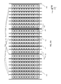
- FIG. 4A illustrates an arrangement of anti-scatter plates of an anti-scatter collimator and detector modules of a CT detector system in accordance with one embodiment of the present disclosure.
- FIG. 4B shows a cross-sectional view illustrating an arrangement of anti-scatter plates of an anti-scatter collimator and detector modules of a CT detector system in accordance with one embodiment of the present disclosure.
- anti-scatter plates 450 are placed above the middle element columns 411 of the detector modules 400 but not on the edge element columns 412 ; anti-scatter plates 450 are also placed above the spacing 423 between two neighboring detector modules 400 .
- a detector system comprises 37 detector modules with each detector module comprising 24 columns by 32 rows of detector elements; detector modules are placed side by side along the arc centered at the X-ray source; anti-scatter plates are aligned to focus on the X-ray source and placed above the center of each element column of each detector module, resulting in 852 (22 middle element columns/module and 37 modules+38 at module spacing including both ends) anti-scatter plates for an entire detector system.
- the edge element column width of the detector modules 400 is smaller than the middle element column width of the detector modules 400 .
- the edge element column width is 0.80 mm
- the middle element column width is 0.915 mm.
- the nominal value of the thickness of the anti-scatter plates 450 may be the difference between the middle element column width and the edge element column width.
- the nominal value of the thickness of the anti-scatter plates is 0.115 mm for the previous example.
- the anti-scatter plate pitch 451 as shown in FIG. 4B which is the distance between two neighboring anti-scatter plates, is arranged in a non-decreasing fashion from the center of a detector module to the two edges of the detector module.
- the anti-scatter plates for each detector module are arranged in the same fashion for the entire anti-scatter collimator of the detector system, resulting in a cyclical function of anti-scatter plate pitch with respect to the fan angle for the entire detector system.
- the anti-scatter collimator comprises two dimensional anti-scatter plates placed along the x-axis and along the z-axis. It will be understood by those skilled in the art that the anti-scatter plates parallel with the x-axis may also be placed above the element rows of the detector modules instead of the gap rows of the detector modules to reduce the tolerance and precision requirements for the manufacturing and assembly of the anti-scatter collimators. While this disclosure has been particularly shown and described with references to the embodiments thereof, it will be understood by those skilled in the art that various changes in forms and details may be made therein without departing from the spirit and scope of the disclosure as defined by the following claims.
Landscapes
- Health & Medical Sciences (AREA)
- Engineering & Computer Science (AREA)
- Life Sciences & Earth Sciences (AREA)
- Physics & Mathematics (AREA)
- Medical Informatics (AREA)
- High Energy & Nuclear Physics (AREA)
- Molecular Biology (AREA)
- Biomedical Technology (AREA)
- General Health & Medical Sciences (AREA)
- Nuclear Medicine, Radiotherapy & Molecular Imaging (AREA)
- Optics & Photonics (AREA)
- Spectroscopy & Molecular Physics (AREA)
- Surgery (AREA)
- Animal Behavior & Ethology (AREA)
- Biophysics (AREA)
- Pathology (AREA)
- Radiology & Medical Imaging (AREA)
- Heart & Thoracic Surgery (AREA)
- Veterinary Medicine (AREA)
- Public Health (AREA)
- General Engineering & Computer Science (AREA)
- General Physics & Mathematics (AREA)
- Pulmonology (AREA)
- Theoretical Computer Science (AREA)
- Apparatus For Radiation Diagnosis (AREA)
- Measurement Of Radiation (AREA)
Abstract
Description
Claims (11)
Priority Applications (2)
| Application Number | Priority Date | Filing Date | Title |
|---|---|---|---|
| US13/908,897 US9076563B2 (en) | 2013-06-03 | 2013-06-03 | Anti-scatter collimators for detector systems of multi-slice X-ray computed tomography systems |
| CN201410233577.7A CN104161535B (en) | 2013-06-03 | 2014-05-29 | The backscattering collimator of the detection system of multilamellar X-ray computerized tomography system |
Applications Claiming Priority (1)
| Application Number | Priority Date | Filing Date | Title |
|---|---|---|---|
| US13/908,897 US9076563B2 (en) | 2013-06-03 | 2013-06-03 | Anti-scatter collimators for detector systems of multi-slice X-ray computed tomography systems |
Publications (2)
| Publication Number | Publication Date |
|---|---|
| US20140355734A1 US20140355734A1 (en) | 2014-12-04 |
| US9076563B2 true US9076563B2 (en) | 2015-07-07 |
Family
ID=51905681
Family Applications (1)
| Application Number | Title | Priority Date | Filing Date |
|---|---|---|---|
| US13/908,897 Active - Reinstated 2033-12-30 US9076563B2 (en) | 2013-06-03 | 2013-06-03 | Anti-scatter collimators for detector systems of multi-slice X-ray computed tomography systems |
Country Status (2)
| Country | Link |
|---|---|
| US (1) | US9076563B2 (en) |
| CN (1) | CN104161535B (en) |
Cited By (3)
| Publication number | Priority date | Publication date | Assignee | Title |
|---|---|---|---|---|
| US20140314200A1 (en) * | 2012-09-19 | 2014-10-23 | Nuctech Company Limited | Ct security inspection system for baggage and detector arrangement thereof |
| EP3208607A1 (en) * | 2016-02-19 | 2017-08-23 | Morpho Detection, LLC | Detector assemblies and methods for helical ct scanning |
| CN110199209A (en) * | 2016-07-28 | 2019-09-03 | 德国史密斯海曼简化股份公司 | Scattering imaging |
Families Citing this family (12)
| Publication number | Priority date | Publication date | Assignee | Title |
|---|---|---|---|---|
| US9968314B1 (en) | 2015-04-14 | 2018-05-15 | Sebring Mechanical Design, Inc. | Steerable X-ray imaging detector module |
| EP3353576B1 (en) * | 2015-09-24 | 2020-07-01 | Prismatic Sensors AB | Modular x-ray detector |
| US10186340B2 (en) | 2016-01-21 | 2019-01-22 | FMI Medical Systems Co., Ltd. | Anti-scatter collimator for high speed rotation |
| US10314553B2 (en) | 2016-01-21 | 2019-06-11 | FMI Medical Systems Co., Ltd. | Focal spot position control using pre-patient collimator with beam tracking |
| US10401507B2 (en) * | 2016-03-24 | 2019-09-03 | Kabushiki Kaisha Toshiba | Collimator, radiation detector, and radiation examination apparatus |
| US10216983B2 (en) | 2016-12-06 | 2019-02-26 | General Electric Company | Techniques for assessing group level cognitive states |
| US11350892B2 (en) * | 2016-12-16 | 2022-06-07 | General Electric Company | Collimator structure for an imaging system |
| US10222489B2 (en) | 2017-03-13 | 2019-03-05 | General Electric Company | Pixel-design for use in a radiation detector |
| US10191162B2 (en) * | 2017-05-05 | 2019-01-29 | Prismatic Sensors Ab | Radiation hard silicon detectors for x-ray imaging |
| US10631815B2 (en) * | 2017-05-10 | 2020-04-28 | General Electric Company | Scatter correction technique for use with a radiation detector |
| CN107582089B (en) * | 2017-09-29 | 2021-06-29 | 上海联影医疗科技股份有限公司 | Collimator, imaging apparatus, focus position tracking method, and correction method |
| US11009471B2 (en) * | 2018-09-12 | 2021-05-18 | Illinois Tool Works Inc. | Dynamic radiation collimation for non destructive analysis of test objects |
Citations (22)
| Publication number | Priority date | Publication date | Assignee | Title |
|---|---|---|---|---|
| US6215843B1 (en) * | 1996-10-30 | 2001-04-10 | Kabushiki Kaisha Toshiba | X-ray CT scanner using X-ray detector acquiring multi-slice data of unequal slice pitches |
| US20030076929A1 (en) * | 2001-10-23 | 2003-04-24 | Siemens Aktiengesellschaft | X-ray detector/stray radiation grid and gamma detector/collimator arrangements |
| US6687333B2 (en) * | 1999-01-25 | 2004-02-03 | Vanderbilt University | System and method for producing pulsed monochromatic X-rays |
| US6733266B1 (en) | 1998-06-26 | 2004-05-11 | General Electric Company | System for fabricating anti-scatter x-ray grid |
| US6778637B2 (en) | 2002-09-20 | 2004-08-17 | Koninklijke Philips Electronics, N.V. | Method and apparatus for alignment of anti-scatter grids for computed tomography detector arrays |
| US20040208277A1 (en) * | 2003-04-21 | 2004-10-21 | Kotoko Morikawa | Radiation computed tomography apparatus and tomographic image producing method |
| US6934354B2 (en) | 2003-05-02 | 2005-08-23 | General Electric Company | Collimator assembly having multi-piece components |
| US7027553B2 (en) * | 2003-12-29 | 2006-04-11 | Ge Medical Systems Global Technology Company, Llc | Systems and methods for generating images by using monochromatic x-rays |
| US20070019779A1 (en) * | 2005-07-19 | 2007-01-25 | Ge Medical Systems Global Technology Company, Llc | X-ray CT apparatus |
| US20070025518A1 (en) * | 2003-06-01 | 2007-02-01 | Simha Levene | Anti-scattering x-ray collimator for ct scanners |
| US7564940B2 (en) | 2003-07-22 | 2009-07-21 | Koninklijke Philips Electronics N.V. | Radiation mask for two dimensional CT detector |
| US20090225953A1 (en) * | 2008-03-10 | 2009-09-10 | Ludwig Danzer | Scattered radiation collimator element, scattered radiation collimator, radiation detector unit and method for producing a scattered radiation absorber element |
| US7590215B2 (en) * | 2004-06-07 | 2009-09-15 | Koninklijke Philips Electronics N.V. | Coherent-scatter computer tomograph |
| US7734017B2 (en) | 2004-08-12 | 2010-06-08 | Koninklijke Philips Electronics N.V. | Anti-scatter-grid for a radiation detector |
| US20100163738A1 (en) * | 2008-12-30 | 2010-07-01 | Ludwig Danzer | Radiation detector, light detector arrangement, production method and imaging system |
| US20100189211A1 (en) * | 2007-07-11 | 2010-07-29 | Koninklijke Philips Electronics N.V. | X-ray souce for measuring radiation |
| US20110075804A1 (en) * | 2009-09-29 | 2011-03-31 | Jan Boese | X-ray imaging method and x-ray imaging system |
| US20120069954A1 (en) * | 2010-09-22 | 2012-03-22 | Toshiba Medical Systems Corporation | X-ray computed tomography apparatus, radiation detector, and method of manufacturing radiation detector |
| US8262288B2 (en) | 2010-01-21 | 2012-09-11 | Analogic Corporation | Focal spot position determiner |
| US20120300907A1 (en) * | 2011-05-26 | 2012-11-29 | Siemens Aktiengesellschaft | Grid module of a scattered-radiation grid, modular scattered-radiation grid, ct detector and ct system |
| US20130163715A1 (en) * | 2011-12-21 | 2013-06-27 | Ge Medical Systems Global Technology Company, Llc | Radiation tomography system, radiation detecting device, and spatial resolution changing method for radiation tomography |
| US20130168567A1 (en) * | 2011-12-28 | 2013-07-04 | General Electric Company | Collimator for a pixelated detector |
Family Cites Families (6)
| Publication number | Priority date | Publication date | Assignee | Title |
|---|---|---|---|---|
| US6618466B1 (en) * | 2002-02-21 | 2003-09-09 | University Of Rochester | Apparatus and method for x-ray scatter reduction and correction for fan beam CT and cone beam volume CT |
| JP3942178B2 (en) * | 2003-07-29 | 2007-07-11 | ジーイー・メディカル・システムズ・グローバル・テクノロジー・カンパニー・エルエルシー | X-ray CT system |
| US8183535B2 (en) * | 2009-02-11 | 2012-05-22 | Mats Danielsson | Silicon detector assembly for X-ray imaging |
| WO2011010995A1 (en) * | 2009-07-21 | 2011-01-27 | Analogic Corporation | Anti-scatter grid or collimator |
| US9078569B2 (en) * | 2012-08-20 | 2015-07-14 | Zhengrong Ying | Configurable data measurement and acquisition systems for multi-slice X-ray computed tomography systems |
| US9285327B2 (en) * | 2013-02-06 | 2016-03-15 | Zhengrong Ying | Adjustable photon detection systems for multi-slice X-ray computed tomography systems |
-
2013
- 2013-06-03 US US13/908,897 patent/US9076563B2/en active Active - Reinstated
-
2014
- 2014-05-29 CN CN201410233577.7A patent/CN104161535B/en active Active
Patent Citations (22)
| Publication number | Priority date | Publication date | Assignee | Title |
|---|---|---|---|---|
| US6215843B1 (en) * | 1996-10-30 | 2001-04-10 | Kabushiki Kaisha Toshiba | X-ray CT scanner using X-ray detector acquiring multi-slice data of unequal slice pitches |
| US6733266B1 (en) | 1998-06-26 | 2004-05-11 | General Electric Company | System for fabricating anti-scatter x-ray grid |
| US6687333B2 (en) * | 1999-01-25 | 2004-02-03 | Vanderbilt University | System and method for producing pulsed monochromatic X-rays |
| US20030076929A1 (en) * | 2001-10-23 | 2003-04-24 | Siemens Aktiengesellschaft | X-ray detector/stray radiation grid and gamma detector/collimator arrangements |
| US6778637B2 (en) | 2002-09-20 | 2004-08-17 | Koninklijke Philips Electronics, N.V. | Method and apparatus for alignment of anti-scatter grids for computed tomography detector arrays |
| US20040208277A1 (en) * | 2003-04-21 | 2004-10-21 | Kotoko Morikawa | Radiation computed tomography apparatus and tomographic image producing method |
| US6934354B2 (en) | 2003-05-02 | 2005-08-23 | General Electric Company | Collimator assembly having multi-piece components |
| US20070025518A1 (en) * | 2003-06-01 | 2007-02-01 | Simha Levene | Anti-scattering x-ray collimator for ct scanners |
| US7564940B2 (en) | 2003-07-22 | 2009-07-21 | Koninklijke Philips Electronics N.V. | Radiation mask for two dimensional CT detector |
| US7027553B2 (en) * | 2003-12-29 | 2006-04-11 | Ge Medical Systems Global Technology Company, Llc | Systems and methods for generating images by using monochromatic x-rays |
| US7590215B2 (en) * | 2004-06-07 | 2009-09-15 | Koninklijke Philips Electronics N.V. | Coherent-scatter computer tomograph |
| US7734017B2 (en) | 2004-08-12 | 2010-06-08 | Koninklijke Philips Electronics N.V. | Anti-scatter-grid for a radiation detector |
| US20070019779A1 (en) * | 2005-07-19 | 2007-01-25 | Ge Medical Systems Global Technology Company, Llc | X-ray CT apparatus |
| US20100189211A1 (en) * | 2007-07-11 | 2010-07-29 | Koninklijke Philips Electronics N.V. | X-ray souce for measuring radiation |
| US20090225953A1 (en) * | 2008-03-10 | 2009-09-10 | Ludwig Danzer | Scattered radiation collimator element, scattered radiation collimator, radiation detector unit and method for producing a scattered radiation absorber element |
| US20100163738A1 (en) * | 2008-12-30 | 2010-07-01 | Ludwig Danzer | Radiation detector, light detector arrangement, production method and imaging system |
| US20110075804A1 (en) * | 2009-09-29 | 2011-03-31 | Jan Boese | X-ray imaging method and x-ray imaging system |
| US8262288B2 (en) | 2010-01-21 | 2012-09-11 | Analogic Corporation | Focal spot position determiner |
| US20120069954A1 (en) * | 2010-09-22 | 2012-03-22 | Toshiba Medical Systems Corporation | X-ray computed tomography apparatus, radiation detector, and method of manufacturing radiation detector |
| US20120300907A1 (en) * | 2011-05-26 | 2012-11-29 | Siemens Aktiengesellschaft | Grid module of a scattered-radiation grid, modular scattered-radiation grid, ct detector and ct system |
| US20130163715A1 (en) * | 2011-12-21 | 2013-06-27 | Ge Medical Systems Global Technology Company, Llc | Radiation tomography system, radiation detecting device, and spatial resolution changing method for radiation tomography |
| US20130168567A1 (en) * | 2011-12-28 | 2013-07-04 | General Electric Company | Collimator for a pixelated detector |
Cited By (6)
| Publication number | Priority date | Publication date | Assignee | Title |
|---|---|---|---|---|
| US20140314200A1 (en) * | 2012-09-19 | 2014-10-23 | Nuctech Company Limited | Ct security inspection system for baggage and detector arrangement thereof |
| US9864091B2 (en) * | 2012-09-19 | 2018-01-09 | Nuctech Company Limited | CT security inspection system for baggage and detector arrangement thereof |
| EP3208607A1 (en) * | 2016-02-19 | 2017-08-23 | Morpho Detection, LLC | Detector assemblies and methods for helical ct scanning |
| US10058293B2 (en) | 2016-02-19 | 2018-08-28 | Morpho Detection, Llc | Detector assemblies and methods for helical CT scanning |
| CN110199209A (en) * | 2016-07-28 | 2019-09-03 | 德国史密斯海曼简化股份公司 | Scattering imaging |
| CN110199209B (en) * | 2016-07-28 | 2021-07-30 | 德国史密斯海曼简化股份公司 | Scatter imaging |
Also Published As
| Publication number | Publication date |
|---|---|
| US20140355734A1 (en) | 2014-12-04 |
| CN104161535A (en) | 2014-11-26 |
| CN104161535B (en) | 2016-06-29 |
Similar Documents
| Publication | Publication Date | Title |
|---|---|---|
| US9076563B2 (en) | Anti-scatter collimators for detector systems of multi-slice X-ray computed tomography systems | |
| US6696686B1 (en) | SPECT for breast cancer detection | |
| JP6043474B2 (en) | Volumetric computed tomography system with tileable multi-plane detector | |
| US10393890B2 (en) | X-ray imaging device | |
| US9835733B2 (en) | Apparatus for detecting X-rays | |
| US7439514B1 (en) | Adjustable pinhole collimators method and system | |
| US8873703B2 (en) | X ray imaging system with scatter radiation correction and method of using same | |
| US9116248B2 (en) | Detector array having effective size larger than actual size | |
| US7569826B2 (en) | Adjustable collimators method and system | |
| US7339174B1 (en) | Combined slit/pinhole collimator method and system | |
| EP2424436B1 (en) | Computed tomography scanning system | |
| EP1802998B1 (en) | Detector for nuclear medicine | |
| US9285327B2 (en) | Adjustable photon detection systems for multi-slice X-ray computed tomography systems | |
| US20140050296A1 (en) | Configurable data measurement and acquisition systems for multi-slice x-ray computed tomography systems | |
| US9089266B2 (en) | Tilted detector array for medical imaging systems including computed tomography | |
| US10492746B2 (en) | Spherical detector for CT system | |
| EP2747656B1 (en) | Whole-body spect system | |
| US20100246753A1 (en) | Fourth Generation Computed Tomography Scanner | |
| JP4508305B2 (en) | Tomographic system and scintillator therefor | |
| JP6395703B2 (en) | Radiation detector and X-ray CT apparatus provided with the same | |
| JP2004337609A (en) | Collimator assembly for computer tomography system | |
| JP5242080B2 (en) | X-ray detector and X-ray CT apparatus | |
| US7470907B2 (en) | Cross-slit collimator method and system | |
| US10473796B2 (en) | Scintillating array with alignment features | |
| US20050161609A1 (en) | X-ray detector module for spectrally resolved measurements |
Legal Events
| Date | Code | Title | Description |
|---|---|---|---|
| STCF | Information on status: patent grant |
Free format text: PATENTED CASE |
|
| FEPP | Fee payment procedure |
Free format text: SURCHARGE FOR LATE PAYMENT, SMALL ENTITY (ORIGINAL EVENT CODE: M2554); ENTITY STATUS OF PATENT OWNER: SMALL ENTITY |
|
| MAFP | Maintenance fee payment |
Free format text: PAYMENT OF MAINTENANCE FEE, 4TH YR, SMALL ENTITY (ORIGINAL EVENT CODE: M2551); ENTITY STATUS OF PATENT OWNER: SMALL ENTITY Year of fee payment: 4 |
|
| FEPP | Fee payment procedure |
Free format text: MAINTENANCE FEE REMINDER MAILED (ORIGINAL EVENT CODE: REM.); ENTITY STATUS OF PATENT OWNER: SMALL ENTITY |
|
| LAPS | Lapse for failure to pay maintenance fees |
Free format text: PATENT EXPIRED FOR FAILURE TO PAY MAINTENANCE FEES (ORIGINAL EVENT CODE: EXP.); ENTITY STATUS OF PATENT OWNER: SMALL ENTITY |
|
| PRDP | Patent reinstated due to the acceptance of a late maintenance fee |
Effective date: 20230825 |
|
| FEPP | Fee payment procedure |
Free format text: PETITION RELATED TO MAINTENANCE FEES FILED (ORIGINAL EVENT CODE: PMFP); ENTITY STATUS OF PATENT OWNER: SMALL ENTITY Free format text: PETITION RELATED TO MAINTENANCE FEES GRANTED (ORIGINAL EVENT CODE: PMFG); ENTITY STATUS OF PATENT OWNER: SMALL ENTITY Free format text: SURCHARGE, PETITION TO ACCEPT PYMT AFTER EXP, UNINTENTIONAL. (ORIGINAL EVENT CODE: M2558); ENTITY STATUS OF PATENT OWNER: SMALL ENTITY |
|
| MAFP | Maintenance fee payment |
Free format text: PAYMENT OF MAINTENANCE FEE, 8TH YR, SMALL ENTITY (ORIGINAL EVENT CODE: M2552); ENTITY STATUS OF PATENT OWNER: SMALL ENTITY Year of fee payment: 8 |
|
| STCF | Information on status: patent grant |
Free format text: PATENTED CASE |
|
| FP | Lapsed due to failure to pay maintenance fee |
Effective date: 20230707 |