TECHNICAL FIELD
The present invention relates to a linear-reciprocating device for linearly reciprocating a moving block along a guide rail so as to interpose a lot of balls between the moving block and the guide rail.
BACKGROUND ART
In order to linearly reciprocate an object to be transported such as a workpiece or a jig and a tool, a linear-reciprocating device is used so as to linearly reciprocate a moving block such as a slider or a table, to which the object to be transported is attached, along a guide rail of a support base. The support base is provided with a drive rod that reciprocates freely in a longitudinal direction of the support base, a protruding end of the drive rod is connected to a distal end of a moving member by a connection block, and the moving member is linearly reciprocated by the reciprocation of the drive rod. The drive rod is driven by a driving source such as a pneumatic cylinder or an electric motor.
By attaching the moving block to the guide rail via balls so as to interpose a lot of balls between the moving block and the guide rail, the moving block which reciprocates along the guide rail can be driven with a small rolling resistance. A lot of balls are housed inside a ball rolling path which is formed of a rolling groove having an almost semicircular shape and being provided to the moving block and a rolling groove having an almost semicircular shape and being provided to the guide rail, and the balls are moved while rolling inside the ball rolling path when the moving block is driven.
The following two types are known as such a ball slider that the moving block is attached to the guide rail via the balls. One of them is an infinite guide type provided with a return hole, that is, a ball circulation hole provided separately from the ball rolling path for circulating the balls between the ball circulation hole and the ball rolling path. The other is a finite guide type in which the balls are not circulated. Patent Document 1 describes the infinite guide type ball slider.
PRIOR ART DOCUMENT
Patent Document
- Patent Document 1: Japanese Patent Application Laid-Open Publication No. 2007-57104
DISCLOSURE OF THE INVENTION
Problems to be Solved by the Invention
In a conventional infinite guide type ball slider, return lid members which communicate between the ball rolling path and the ball circulation hole are provided to both ends of the moving block. Therefore, when the moving block is moved to a position at which the moving block is protruded from an end of the guide rail, the balls fall out of the ball rolling groove, and therefore, the moving block cannot be driven to a position at which an end of the moving block is protruded from the guide rail.
For example, in a linear-reciprocating device of such a type that the driving source for driving the moving block is housed in the support base provided with the guide rail, the moving block is protruded from a distal end of the support base or guide rail when the drive rod driven by the driving source so as to be protruded from the support base is connected to the moving block. Practically, such a protruding structure is impossible, and therefore, the following structure is practically adopted. It is required to protrude a drive member reciprocated by the driving source inside the support base from a slit formed on the guide rail so that a slider or the drive member is engaged with an inner surface of the moving block, and therefore, the structure of the guide rail is complicated. If the structures of the guide rail and the slider are complicated, their heights are increased, and therefore, the linear-reciprocating device cannot be downsized.
A preferred aim of the present invention is to achieve the downsizing of the linear-reciprocating device.
Means for Solving the Problems
A linear-reciprocating device of the present invention has a feature of a linear-reciprocating device for linearly reciprocating a moving block attached to a guide rail provided to a support base so as to freely reciprocate, and the linear-reciprocating device includes: a first ball rolling groove formed on a side surface of the guide rail so as to face a side surface of a guide groove which is formed on an inner surface of the moving block and into which the guide rail is inserted; a second ball rolling groove formed on a base end side of the guide groove and forming a ball rolling path together with the first ball rolling groove; a lot of balls housed in the ball rolling path and in a ball circulation hole formed along the ball rolling path; a return lid member provided to a base end of the moving block to form a base-end-side ball return path for communication between the ball rolling path and the ball circulation hole; and a return block provided to a longitudinal-directional middle area of the moving block to form a middle-side ball return path for communication between the ball rolling path and the ball circulation hole. In the linear-reciprocating device, the moving block is guided by the balls to a position at which a distal end of the moving block is protruded from a distal end of the guide rail.
The linear-reciprocating device of the present invention has such a feature that an attachment concave portion to which the return block is attached is formed in a longitudinal-directional middle area of an inner surface of the moving block. The linear-reciprocating device of the present invention has such a feature that an abutment surface on which the return block is abutted is formed in a longitudinal-directional middle area of an inner surface of the moving block. The linear-reciprocating device of the present invention has such a feature that the first ball rolling groove is provided to both sides of the guide rail, and that the second ball rolling groove is provided to both side surfaces of the guide groove of the moving block. The linear-reciprocating device of the present invention has such a feature that the two return lid members provided to both sides of the moving block are integrally formed with each other by a connecting portion.
The linear-reciprocating device of the present invention has such a feature that the two return blocks provided to both sides of the moving block are integrally formed with each other by a connecting portion. The linear-reciprocating device of the present invention has such a feature that the ball circulation hole is formed at a horizontal position along a surface of the guide rail with respect to the ball rolling path. The linear-reciprocating device of the present invention has such a feature that a guide fit hole in which a return groove is formed on each of the return lid member and the return block is provided, and that a return groove for forming the ball return path together with the above-described return groove is provided to a return guide fitted into the guide fit hole. The linear-reciprocating device of the present invention has such a feature that the return guides attached to the return lid member and the return block are formed in the same shape as each other. The linear-reciprocating device of the present invention has such a feature that a drive rod provided to the support base is connected to a distal end of the moving block, and that the moving block is reciprocated by the drive rod protruded from a distal end surface of the support base.
Effects of the Invention
In a linear-reciprocating device of the present invention, a ball rolling path is formed of a first ball rolling groove provided to a guide rail and a second ball rolling groove provided on a base end side of a moving block. A ball circulation hole which is communicated into the ball rolling path is provided to the base end. A middle-side ball return path which communicates between the ball rolling path and the ball circulation hole is provided in a longitudinal-directional middle area of the moving block. Therefore, the moving block can be moved to a position at which the moving block is protruded while rolling balls from a distal end of the guide rail.
Since the moving block can be moved to the position at which the moving block is protruded from the distal end of the guide rail, a drive rod for driving the moving block can be provided to a support base, and the drive rod can be connected to a distal end of the moving block. In this manner, in comparison with a case that the drive source and the moving block are connected to each other inside the support base, a structure of the linear-reciprocating device is not complicated, and the linear-reciprocating device can be downsized by forming a thickness of the structure to be thin. Since the guide rail is provided to the support base, the drive source for driving the drive rod can be protruded into the guide rail so as to downsize the linear-reciprocating device including the guide rail and the support base.
BRIEF DESCRIPTIONS OF THE DRAWINGS
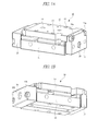
FIG. 1A is a perspective view of a linear-reciprocating device as viewed from above in a state that a moving block moves backward, and FIG. 1B is a perspective view of the linear-reciprocating device illustrated in FIG. 1A as viewed from below;
FIG. 2A is a perspective view of a linear-reciprocating device as viewed from above in a state that a moving block moves forward, and FIG. 2B is a perspective view of the linear-reciprocating device illustrated in FIG. 2A as viewed from below;
FIG. 3 is a cross-sectional view of FIG. 1A;
FIG. 4 is a cross-sectional view taken along a line 4-4 in FIG. 3;
FIG. 5 is a cross-sectional view taken along a line 5-5 in FIG. 3;
FIG. 6 is an exploded perspective view of a return lid member, a return block, and inner surfaces of the moving block from which the return lid member and the return block are detached, as viewed from above;
FIG. 7 is an enlarged perspective view of the return lid member illustrated in FIG. 6;
FIG. 8 is an exploded perspective view of a return guide and the return lid member from which the return guide is detached;
FIG. 9 is an enlarged perspective view of the return block illustrated in FIG. 6;
FIG. 10 is an exploded perspective view of the return guide and the return block from which the return guide is detached;
FIG. 11 is a perspective view illustrating a modification example of the return lid member;
FIG. 12 is a perspective view of the return lid member illustrated in FIG. 11 as view from an opposite side;
FIG. 13 is a perspective view illustrating a modification example of the return block;
FIG. 14 is a perspective view of the return block illustrated in FIG. 13 as view from an opposite side;
FIG. 15 is a perspective view illustrating a modification example of the moving block;
FIG. 16 is a cross-sectional view illustrating a modification example of the linear-reciprocating device; and
FIG. 17 is a cross-sectional view illustrating a modification example of a driving source of the linear-reciprocating device.
BEST MODE FOR CARRYING OUT THE INVENTION
Hereinafter, an embodiment of the present invention will be described in detail based on drawings. As illustrated in FIGS. 1 and 2, a linear-reciprocating device 10 includes a support base 11. As illustrated in FIGS. 4 and 5, in the drawing, a guide rail 12 is formed in a width-directional middle area of an upper surface of the support base 11 so as to protrude upward and extend in the longitudinal direction. A moving table, that is, a moving block 13 is attached along the guide rail 12 so as to freely linearly reciprocate. In order to drive the moving block 13, a driving source is housed inside the support base 11. A drive rod 14 driven by the driving source is protruded from a distal end of the support base 11 as illustrated in FIG. 2A. A linear motor 15 having the drive rod 14 as a movable member is used as the driving source, and the linear motor 15 has a magnet 16 attached to the drive rod 14 and a coil 17 that is housed inside the support base 11 so as to surround the magnet 16 as illustrated in FIGS. 4 and 5.
A connection block 18 is fixed to the distal end of the drive rod 14 by a screw member 19, and the connection block 18 is also fixed to a distal end of the moving block 13 by a screw member 19 a. The drive rod 14 is connected to the distal end of the moving block 13, that is, one end thereof, and the other end opposite to the distal end serves as a base end. An electric power supply block 20 is attached to a base end surface of the support base 11 by a screw member 19 b, and a non-illustrated signal cable for supplying a drive signal to the coil 17 of the linear motor is connected to the electric power supply block 20.
As illustrated in FIGS. 3 to 5, ball rolling grooves 21 a and 21 b each of which has an almost semi-circular cross-sectional shape are provided on both side surfaces 12 a and 12 b of the guide rail 12 over the whole length of the guide rail 12 as a first rolling groove. As illustrated in FIG. 6, a guide groove 22 to which the guide rail 12 is inserted is provided to the width-directional middle area of an inner surface of the moving block 13 over the whole length. When the moving block 13 is attached to the support base 11, the guide rail 12 is inserted into the guide groove 22 so that the both side surfaces 12 a and 12 b of the guide rail 12 face both side surfaces 22 a and 22 b of the guide groove 22, respectively.
On an inner side surface of the guide groove 22 at the base end of the moving block 13, ball rolling grooves 23 a and 23 b each of which has an almost semi-circular cross-sectional shape are provided as a second rolling groove. A ball rolling path 24 a is formed of the ball rolling grooves 21 a and 23 a facing each other, and a ball rolling path 24 b is formed of the ball rolling grooves 21 b and 23 b facing each other.
Return holes, that is, ball circulation holes 25 a and 25 b are formed on the base end of the moving block 13, and the ball circulation holes 25 a and 25 b are in parallel with the ball rolling paths 24 a and 24 b, respectively. A looped infinite circulation path is formed of a pair of the ball rolling path 24 a and the ball circulation hole 25 a, and a circulation path is similarly formed of a pair of the ball rolling path 24 b and the ball circulation hole 25 b. A lot of balls 26 are housed in each circulation path. The ball circulation holes 25 a and 25 b are formed in parallel with the ball rolling paths 24 a and 24 b on a horizontal plane along the surface of the guide rail 12, respectively.
By providing the guide rail 12 integrally on the support base 11 and providing the guide groove 22 into which the guide rail 12 is inserted on the inner surface of the moving block 13, the moving block 13 is attached to the guide rail 12 so as to straddle the guide rail 12. The ball circulation holes 25 a and 25 b are formed in parallel with the ball rolling paths 24 a and 24 b on the horizontal plane along the surface of the guide rail 12, respectively. In addition, as illustrated in FIGS. 4 and 5, the linear motor 15 is housed so as to protrude from the support base 11 into the guide rail 12. In this manner, a total thickness of the support base 11 and the moving block 13 can be reduced, so that a height of the linear-reciprocating device 10 in an up-and-down direction in FIGS. 4 and 5 can be reduced.
As illustrated in FIG. 3, to the base end surface of the moving block 13, a return lid member 27 a that communicates between the ball rolling path 24 a and the ball circulation hole 25 a and a return lid member 27 b that communicates between the ball rolling path 24 b and the ball circulation hole 25 b are attached. On the base end side of the moving block 13, the return lid member 27 a communicates between the ball rolling path 24 a and the ball circulation hole 25 a, and the return lid member 27 b communicates between the ball rolling path 24 b and the ball circulation hole 25 b. As illustrated in FIG. 3, a circular protrusion 28 is provided to abutment surfaces of the return lid members 27 a and 27 b, respectively, and a fit hole 29 with which the protrusion 28 is fitted is provided to the base end surface of the moving block 13. Each of the return lid members 27 a and 27 b is fastened to the moving block 13 by a screw member 30 screwed with a female screw that is provided to the moving block 13 so as to be coaxial with the fit hole 29.
Attachment concave portions 31 a and 31 b are provided to the inner surface of the moving block 13 so as to be positioned in a longitudinal-directional middle area. To the attachment concave portions 31 a and 31 b, the return blocks 32 a and 32 b are provided, respectively. The return block 32 a communicates between the ball rolling path 24 a and the ball circulation hole 25 a in the longitudinal-directional middle area of the moving block 13, and the return block 32 b communicates between the ball rolling path 24 b and the ball circulation hole 25 b in the longitudinal-directional middle area of the moving block 13. In order to fix each of the return blocks 32 b and 32 b to the moving block 13, a screw member 33 screwed into a screw hole formed on the moving block 13 is attached to an attachment hole 34 provided to the return blocks 32 b and 32 b.
When the moving block 13 linearly reciprocates, the moving block 13 moves along the guide rail 12 via a lot of balls 26, and therefore, a rolling resistance applied to the moving block 13 is reduced, and the moving block 13 can be reciprocated smoothly with a small power. When the moving block 13 is driven, the balls 26 are circulated inside the looped continuous circulation path. The ball rolling paths 24 a and 24 b are provided on the base end side of the moving block 13, and the balls 26 do not fall off the inside of the circulation path even if the distal end of the moving block 13 protrudes from the distal end of the guide rail 12 as illustrated in FIG. 2.
In this manner, even if the moving block 13 moves to a position at which the moving block 13 protrudes from the guide rail 12 of the support base 11, the balls 26 can be interposed between the moving block 13 and the guide rail 12. That is, even if the drive rod 14 protruding from the distal end surface of the support base 11 is connected to the distal end of the moving block 13, the moving block 13 can be driven by the drive rod 14. In order to restrict a moving-forward limitation position of the moving block 13, a stopper 35 is attached to the distal end surface of the support base 11 as illustrated in FIG. 3.
While each of the support base 11 and the moving block 13 is made of a metal material, each of the return lid members 27 a and 27 b and the return blocks 32 a and 32 b is made of a resin material. As illustrated in FIG. 6, the return lid members 27 a and 27 b are provided integrally to both ends of a first connecting portion 36 so as to protrude from the first connecting portion 36. A guide groove 37 into which the guide rail 12 is inserted is formed of the return lid members 27 a and 27 b and the first connecting portion 36. Similarly, the return blocks 32 a and 32 b are provided integrally to both ends of a second connecting portion 38 so as to protrude from the second connecting portion 38. A guide groove 39 into which the guide rail 12 is inserted is formed of the return blocks 32 a and 32 b and the second connecting portion 38. On the inner surface of the moving block 13, an attachment groove to which the second connecting portion 38 is attached is provided so as to be continuous from the attachment concave portions 31 a and 31 b.
As illustrated in FIG. 8, guide fit holes 41 a and 41 b each having a semi-circular cross-sectional surface are formed on the return lid members 27 a and 27 b, and first return grooves 42 a and 42 b opened to the guide fit holes 41 a and 41 b are also formed on the return lid members 27 a and 27 b, respectively. Each of the first return grooves 42 a and 42 b has an almost semi-circular cross-sectional surface, and extends in the longitudinal direction as a semi-circular shape. Each of return guides 43 a and 43 b each of which has an almost semi-circular cross-sectional surface is fitted to the guide fit holes 41 a and 41 b, and the return guides 43 a and 43 b are provided with second return grooves 45 a and 45 b which form base-end-side ball return paths 44 a and 44 b together with the return grooves 42 a and 42 b, respectively. As similar to the return grooves 42 a and 42 b, each of the second return grooves 45 a and 45 b has an almost semi-circular cross-sectional surface, and extends in the longitudinal direction as a semi-circular shape.
In order to fix the return guides 43 a and 43 b to the return lid members 27 a and 27 b, attachment holes 47 a and 47 b to which pins 46 are attached are provided to the return guides 43 a and 43 b, and fit holes 48 a and 48 b to which the pins 46 are attached are provided ti the return lid members 27 a and 27 b as illustrated in FIG. 6, respectively.
Similarly as illustrated in FIG. 10, guide fit holes 51 a and 51 b each of which has a semi-circular cross-sectional surface are formed on the return blocks 32 a and 32 b, and return grooves 52 a and 52 b opened to the guide fit holes 51 a and 51 b are also provided to the return blocks 32 a and 32 b, respectively. Each of the return grooves 52 a and 52 b has an almost semi-circular cross-sectional surface, and extends in the longitudinal direction as a semi-circular shape. Return guides 53 a and 53 b each having an almost semi-circular cross-sectional surface are fitted to the guide fit holes 51 a and 51 b, and return grooves 55 a and 55 b for forming middle-side ball return paths 54 a and 54 b together with the return grooves 52 a and 52 b are provided to the return guides 53 a and 53 b, respectively. As similar to the return grooves 52 a and 52 b, each of the return grooves 55 a and 55 b has an almost semi-circular cross-sectional surface, and extends in the longitudinal direction as a semi-circular shape.
In order to fix the return guides 53 a and 53 b to the return blocks 32 a and 32 b, respectively, attachment holes 57 a and 57 b to which a pin 56 is attached are provided to the return guides 53 a and 53 b, and, fit holes 58 a and 58 b to which the pin 56 is attached are provided to the return blocks 32 a and 32 b as illustrated in FIG. 10, respectively.
The return guides 43 a and 43 b are fixed to the return lid members 27 a and 27 b by using the pin 46. However, the return guides 43 a and 43 b may be fixed to the return lid members 27 a and 27 b by using a snap fit manner, welding, or bonding, or may be fixed to the guide fit holes 41 a and 41 b by using a press fit manner. As similar to the return guides 43 a and 43 b, the return guides 53 a and 53 b may be fixed to the return blocks 32 a and 32 b.
As illustrated in FIGS. 1 and 2, a plurality of screw holes 61 are provided outside the guide rail 12 in a width direction, the screw holes 61 each being screwed with a screw member for fixing the support base 11 to a not-illustrated board, and screw holes 62 are also provided on both left and right side surfaces. A plurality of screw holes 63 and a plurality of positioning holes 64 are provided to the moving block 13, the screw holes 63 to which a member to be transported such as a jig and tool arranged on an outer surface of the moving block 13 is attached, and the positioning holes 64 which positions the member to be transported.
To one linear-reciprocating device 10, four return guides 43 a, 43 b, 53 a, and 53 b are attached. These return guides have the same shape as each other, so that any return guide can be mounted on the return lid members 27 a and 27 b and the return blocks 32 a and 32 b. In this manner, components can be easily managed in the assembly of the linear-reciprocating device 10.
As described above, since two return lid members 27 a and 27 b are connected integrally to each other by the first connecting portion 36, both return lid members 27 a and 27 b can be simultaneously attached to the moving block 13 by one attachment operation. Similarly, since two return blocks 32 a and 32 b are connected integrally to each other by the second connecting portion 38, both return blocks 32 a and 32 b can be simultaneously attached to the moving block 13 by one attachment operation. If the return lid members 27 a and 27 b are separation forms, each of them is separately attached to the moving block 13. Similarly, if the return blocks 32 a and 32 b are separation forms, each of them is separately attached to the moving block 13.
FIG. 11 is a perspective view illustrating the return lid members 27 a and 27 b as a modification example, FIG. 12 is a perspective view of the return lid members of FIG. 11 as viewed from an opposite side, FIG. 13 is a perspective view of the return blocks 32 a and 32 b as a modification example, and FIG. 14 is a perspective view of the return blocks of FIG. 13 as viewed from an opposite side. In these drawings, common components with the above-described components are denoted by the same reference symbols.
The return lid members 27 a and 27 b illustrated in FIGS. 11 and 12 are separation forms, and therefore, each of them is separately attached to the moving block 13. Similarly, the return blocks 32 a and 32 b illustrated in FIGS. 13 and 14 are also separation forms, and therefore, each of them is separately attached to the moving block 13.
FIG. 15 is a perspective view illustrating a modification example of the moving block 13. Although the guide groove 22 is provided to this moving block 13 on a base end side, and the guide groove 22 is not provided thereto on a distal end side. The return lid members 27 a and 27 b illustrated in FIG. 7 or 11 are attached to the base end surface of the moving block 13, and the return blocks 32 a and 32 b illustrated in FIG. 9 or 13 are attached to the moving block 13 so as to be abutted onto an abutment surface 65 provided in a longitudinal-directional middle area of the moving block 13.
FIG. 16 is a cross-sectional view illustrating a modification example of the linear-reciprocating device 10, and FIG. 16 illustrates the same part as FIG. 15.
As illustrated in FIG. 16, in this linear-reciprocating device 10, two ball rolling grooves 21 a and 21 a are provided to a side surface 12 a of the guide rail 12 so as to vertically interpose a gap therebetween, and two ball rolling grooves 21 b and 21 b are provided to a side surface 12 b of the guide rail 12 so as to vertically interpose a gap therebetween. Two vertically-arranged ball rolling grooves 23 a and 23 a are provided to a side surface 22 a of the guide groove 22 so as to face the two ball rolling grooves 21 a and 21 a, and two vertically-arranged ball rolling grooves 23 b and 23 b are provided to a side surface 22 b of the guide groove 22 so as to face the two ball rolling grooves 21 b and 21 b.
FIG. 17 is a cross-sectional view illustrating a modification example of the driving source of the linear-reciprocating device 10. While the linear motor 15 is housed as the driving source inside the support base 11 in the above-described linear-reciprocating device 10, a pneumatic cylinder 70 is housed as the driving source inside the support base 11 in the linear-reciprocating device 10 illustrated in FIG. 17.
A cylinder hole 71 is provided into the support base 11, and a piston 72 is attached to the base end of the drive rod 14. A cover 73 is attached to the base end of the support base 11, and a cover 74 thorough which the drive rod 14 penetrates is attached to the distal end of the support base 11. The cylinder hole 71 is partitioned by the piston 72 into a pneumatic chamber 71 a for moving the rod forward and a pneumatic chamber 71 b for moving the rod backward, and compressed air is supplied from a not-illustrated inlet/outlet port to each of the pneumatic chambers 71 a and 71 b. By supplying the compressed air to the pneumatic chamber 71 a, the moving block 13 is moved forward from a moving-backward limit position illustrated in FIG. 17 toward a moving-forward limit position. On the other hand, by supplying the compressed air to the pneumatic chamber 71 b, the moving block 13 is moved backward from the moving-forward limit position toward the moving-backward limit position.
As described above, the moving block 13 is driven to be reciprocated by the drive rod 14 between the moving-backward limit position illustrated in FIG. 1 and the moving-forward limit position illustrated in FIG. 2. In this reciprocation, the moving block 13 is supported via the balls 26 circulating between the guide rail 12 and the moving block 13, and therefore, can be smoothly reciprocated.
The balls 26 are circulated through the ball rolling paths 24 a and 24 b and the ball circulation holes 25 a and 25 b provided on the base end side of the moving block 13, and therefore, the moving block 13 can be moved to a position at which the moving block 13 is protruded from the distal end of the guide rail 12. On the other hand, when a slit for connecting a drive member such as a slider with the moving block 13 is conventionally provided to the support base 11, a height of the linear-reciprocating device 10 increases. However, since the moving block 13 is driven by the drive rod 14 protruded from the distal end surface of the support base 11 as illustrated, a small linear-reciprocating device 10 having a small height can be provided even when the moving block 13 is driven by the driving source provided to the support base 11.
If the guide rail 12 is attached to the support base 11 so that the support base 11 and the guide rail 12 are member separately formed from each other, and if the driving source is provided inside the support base 11, a large height of the linear-reciprocating device including the support base 11 and the guide rail 12 cannot be avoided. On the other hand, if the support base 11 and the guide rail 12 are integrally formed with each other so that the guide rail 12 is inserted into the guide groove 22 formed on the inner surface of the moving block 13 and so that the moving block 13 is attached to the guide rails 12 to straddle between the guide rails 12, the driving source can be embedded even inside the guide rail 12, which results in the small height of the linear-reciprocating device. In this manner, the linear-reciprocating device 10 can be downsized.
The present invention is not limited to the above-described embodiment and various modifications can be made within the scope of the present invention. For example, in the above-described linear-reciprocating device 10, the moving block 13 is driven by the driving source provided inside the support base 11. However, other aspect that the moving block 13 is driven by the driving source arranged outside the support base 11 may be adopted.
INDUSTRIAL APPLICABILITY
This linear-reciprocating device is applied to move an object to be transported such as a workpiece or a jig and a tool.