US9050170B2 - Ophthalmic laser treatment apparatus - Google Patents

Ophthalmic laser treatment apparatus Download PDF

Info

Publication number
US9050170B2
US9050170B2 US13/073,217 US201113073217A US9050170B2 US 9050170 B2 US9050170 B2 US 9050170B2 US 201113073217 A US201113073217 A US 201113073217A US 9050170 B2 US9050170 B2 US 9050170B2
Authority
US
United States
Prior art keywords
irradiation
pattern
irradiation pattern
spot
laser beam
Prior art date
Legal status (The legal status is an assumption and is not a legal conclusion. Google has not performed a legal analysis and makes no representation as to the accuracy of the status listed.)
Active, expires
Application number
US13/073,217
Other versions
US20110245815A1 (en
Inventor
Hitoshi Abe
Current Assignee (The listed assignees may be inaccurate. Google has not performed a legal analysis and makes no representation or warranty as to the accuracy of the list.)
Nidek Co Ltd
Original Assignee
Nidek Co Ltd
Priority date (The priority date is an assumption and is not a legal conclusion. Google has not performed a legal analysis and makes no representation as to the accuracy of the date listed.)
Filing date
Publication date
Application filed by Nidek Co Ltd filed Critical Nidek Co Ltd
Assigned to NIDEK CO., LTD. reassignment NIDEK CO., LTD. ASSIGNMENT OF ASSIGNORS INTEREST (SEE DOCUMENT FOR DETAILS). Assignors: ABE, HITOSHI
Publication of US20110245815A1 publication Critical patent/US20110245815A1/en
Priority to US14/703,275 priority Critical patent/US9308129B2/en
Application granted granted Critical
Publication of US9050170B2 publication Critical patent/US9050170B2/en
Active legal-status Critical Current
Adjusted expiration legal-status Critical

Links

Images

Classifications

    • AHUMAN NECESSITIES
    • A61MEDICAL OR VETERINARY SCIENCE; HYGIENE
    • A61FFILTERS IMPLANTABLE INTO BLOOD VESSELS; PROSTHESES; DEVICES PROVIDING PATENCY TO, OR PREVENTING COLLAPSING OF, TUBULAR STRUCTURES OF THE BODY, e.g. STENTS; ORTHOPAEDIC, NURSING OR CONTRACEPTIVE DEVICES; FOMENTATION; TREATMENT OR PROTECTION OF EYES OR EARS; BANDAGES, DRESSINGS OR ABSORBENT PADS; FIRST-AID KITS
    • A61F9/00Methods or devices for treatment of the eyes; Devices for putting-in contact lenses; Devices to correct squinting; Apparatus to guide the blind; Protective devices for the eyes, carried on the body or in the hand
    • A61F9/007Methods or devices for eye surgery
    • A61F9/008Methods or devices for eye surgery using laser
    • A61F9/00821Methods or devices for eye surgery using laser for coagulation
    • AHUMAN NECESSITIES
    • A61MEDICAL OR VETERINARY SCIENCE; HYGIENE
    • A61BDIAGNOSIS; SURGERY; IDENTIFICATION
    • A61B18/00Surgical instruments, devices or methods for transferring non-mechanical forms of energy to or from the body
    • A61B2018/00571Surgical instruments, devices or methods for transferring non-mechanical forms of energy to or from the body for achieving a particular surgical effect
    • A61B2018/00589Coagulation
    • AHUMAN NECESSITIES
    • A61MEDICAL OR VETERINARY SCIENCE; HYGIENE
    • A61BDIAGNOSIS; SURGERY; IDENTIFICATION
    • A61B18/00Surgical instruments, devices or methods for transferring non-mechanical forms of energy to or from the body
    • A61B2018/00988Means for storing information, e.g. calibration constants, or for preventing excessive use, e.g. usage, service life counter
    • AHUMAN NECESSITIES
    • A61MEDICAL OR VETERINARY SCIENCE; HYGIENE
    • A61BDIAGNOSIS; SURGERY; IDENTIFICATION
    • A61B18/00Surgical instruments, devices or methods for transferring non-mechanical forms of energy to or from the body
    • A61B18/18Surgical instruments, devices or methods for transferring non-mechanical forms of energy to or from the body by applying electromagnetic radiation, e.g. microwaves
    • A61B18/20Surgical instruments, devices or methods for transferring non-mechanical forms of energy to or from the body by applying electromagnetic radiation, e.g. microwaves using laser
    • A61B2018/2015Miscellaneous features
    • A61B2018/2025Miscellaneous features with a pilot laser
    • AHUMAN NECESSITIES
    • A61MEDICAL OR VETERINARY SCIENCE; HYGIENE
    • A61BDIAGNOSIS; SURGERY; IDENTIFICATION
    • A61B18/00Surgical instruments, devices or methods for transferring non-mechanical forms of energy to or from the body
    • A61B18/18Surgical instruments, devices or methods for transferring non-mechanical forms of energy to or from the body by applying electromagnetic radiation, e.g. microwaves
    • A61B18/20Surgical instruments, devices or methods for transferring non-mechanical forms of energy to or from the body by applying electromagnetic radiation, e.g. microwaves using laser
    • A61B2018/2035Beam shaping or redirecting; Optical components therefor
    • A61B2018/20351Scanning mechanisms
    • A61B2018/20359Scanning mechanisms by movable mirrors, e.g. galvanometric
    • AHUMAN NECESSITIES
    • A61MEDICAL OR VETERINARY SCIENCE; HYGIENE
    • A61BDIAGNOSIS; SURGERY; IDENTIFICATION
    • A61B18/00Surgical instruments, devices or methods for transferring non-mechanical forms of energy to or from the body
    • A61B18/18Surgical instruments, devices or methods for transferring non-mechanical forms of energy to or from the body by applying electromagnetic radiation, e.g. microwaves
    • A61B18/20Surgical instruments, devices or methods for transferring non-mechanical forms of energy to or from the body by applying electromagnetic radiation, e.g. microwaves using laser
    • A61B2018/2035Beam shaping or redirecting; Optical components therefor
    • A61B2018/205545Arrangements for particular spot shape, e.g. square or annular
    • AHUMAN NECESSITIES
    • A61MEDICAL OR VETERINARY SCIENCE; HYGIENE
    • A61BDIAGNOSIS; SURGERY; IDENTIFICATION
    • A61B18/00Surgical instruments, devices or methods for transferring non-mechanical forms of energy to or from the body
    • A61B18/18Surgical instruments, devices or methods for transferring non-mechanical forms of energy to or from the body by applying electromagnetic radiation, e.g. microwaves
    • A61B18/20Surgical instruments, devices or methods for transferring non-mechanical forms of energy to or from the body by applying electromagnetic radiation, e.g. microwaves using laser
    • A61B2018/2035Beam shaping or redirecting; Optical components therefor
    • A61B2018/205547Controller with specific architecture or programmatic algorithm for directing scan path, spot size or shape, or spot intensity, fluence or irradiance
    • AHUMAN NECESSITIES
    • A61MEDICAL OR VETERINARY SCIENCE; HYGIENE
    • A61FFILTERS IMPLANTABLE INTO BLOOD VESSELS; PROSTHESES; DEVICES PROVIDING PATENCY TO, OR PREVENTING COLLAPSING OF, TUBULAR STRUCTURES OF THE BODY, e.g. STENTS; ORTHOPAEDIC, NURSING OR CONTRACEPTIVE DEVICES; FOMENTATION; TREATMENT OR PROTECTION OF EYES OR EARS; BANDAGES, DRESSINGS OR ABSORBENT PADS; FIRST-AID KITS
    • A61F9/00Methods or devices for treatment of the eyes; Devices for putting-in contact lenses; Devices to correct squinting; Apparatus to guide the blind; Protective devices for the eyes, carried on the body or in the hand
    • A61F9/007Methods or devices for eye surgery
    • A61F9/008Methods or devices for eye surgery using laser
    • A61F2009/00861Methods or devices for eye surgery using laser adapted for treatment at a particular location
    • A61F2009/00863Retina
    • AHUMAN NECESSITIES
    • A61MEDICAL OR VETERINARY SCIENCE; HYGIENE
    • A61FFILTERS IMPLANTABLE INTO BLOOD VESSELS; PROSTHESES; DEVICES PROVIDING PATENCY TO, OR PREVENTING COLLAPSING OF, TUBULAR STRUCTURES OF THE BODY, e.g. STENTS; ORTHOPAEDIC, NURSING OR CONTRACEPTIVE DEVICES; FOMENTATION; TREATMENT OR PROTECTION OF EYES OR EARS; BANDAGES, DRESSINGS OR ABSORBENT PADS; FIRST-AID KITS
    • A61F9/00Methods or devices for treatment of the eyes; Devices for putting-in contact lenses; Devices to correct squinting; Apparatus to guide the blind; Protective devices for the eyes, carried on the body or in the hand
    • A61F9/007Methods or devices for eye surgery
    • A61F9/008Methods or devices for eye surgery using laser
    • A61F2009/00897Scanning mechanisms or algorithms

Definitions

  • the present invention relates to an ophthalmic laser treatment apparatus for treatment a patient's eye by irradiation a laser beam thereto.
  • a photocoagulation apparatus As one of ophthalmic laser treatment apparatuses, a photocoagulation apparatus is known.
  • photocoagulation treatment e.g., panretinal photocoagulation treatment
  • a treatment laser beam is sequentially irradiated on a spot-by-spot basis to fundus tissues of a patient's eye to thermally photocoagulate the tissues.
  • a visible aiming beam is first irradiated for aiming of the treatment laser beam (for example, see JP 2002-224154A).
  • a scanning unit including a galvano mirror and others is installed in a laser-beam delivery unit to scan a treatment laser beam in the form of a spot onto fundus tissues based on a plurality of irradiation patterns of spot positions set in advance (for example, see JP 2006-524515A and JP 2009-514564A).
  • This apparatus stores in advance a plurality of predetermined irradiation patterns in a memory, for example, a pattern of spots arranged in a square matrix of 3 ⁇ 3, 5 ⁇ 5, or others, a pattern of spots arranged in a circular form (including a fan-like form), and others so that a desired irradiation pattern is selectable by an operator according to the condition of the tissues.
  • the aiming beam is also irradiated based on the irradiation patterns.
  • the irradiation patterns stored in the memory are typical arrangement patterns of spots. All combination patterns are not always prepared in advance. If all irradiation patterns are stored in the memory, a selection procedure to select a desired pattern is complex and hence operationality is poor. However, if only the previously prepared irradiation patterns are available, one or some spots may fall on a treatment area to which laser irradiation should be avoided according on the condition of the area.
  • an irradiation pattern of 5 ⁇ 5 spots is selected for irradiating a laser beam to a wide range of eye fundus is assumed.
  • a part of the spots i.e., spots S 14 and S 25 , are likely to fall on a blood vessel V.
  • a circular arc pattern (a circular arc irradiation pattern of spots arranged in a circular arc with a predetermined curvature) is selected from the irradiation patterns stored in the memory.
  • the laser beam of this circular arc pattern is repeated plural times to arrange the spots in a circular form.
  • the spots could not be arranged in the circular form depending on the condition and the curvature of the fundus of the patient's eye.
  • the present invention has been made to solve the above problems and has a purpose to provide an ophthalmic laser treatment apparatus capable of performing efficient and appropriate treatment by effectively utilizing previously prepared irradiation patterns.
  • an ophthalmic laser treatment apparatus for treating a patient's eye by irradiating a treatment laser beam thereto, comprising: an irradiation unit including a treatment laser source, and a scanner for scanning an irradiation spot of the treatment beam from the laser source onto a tissue of the patient's eye in two dimensions; a memory for storing a plurality of predetermined irradiation patterns in each of which a plurality of the irradiation spots of the treatment beam are arranged in a predetermined arrangement; an irradiation pattern selecting unit including a selection switch for inputting a signal to select a desired irradiation pattern from the irradiation patterns stored in the memory; an irradiation pattern changing unit including a change switch for inputting a signal to change a part of the arrangement of the irradiation pattern in which the irradiation spots are arranged on the basis of the selected irradiation pattern by the irradiation pattern
  • FIG. 1 is a schematic configuration view of optical systems and a control system in an ophthalmic laser treatment apparatus
  • FIG. 2 is a perspective view of a scanner
  • FIG. 3 is a view showing one example of patterns
  • FIGS. 4A and 4B are explanatory views of laser irradiation in a 5 ⁇ 5 irradiation pattern
  • FIG. 5 is a view showing an example of a screen for an irradiation pattern changing mode related to a 5 ⁇ 5 irradiation pattern
  • FIGS. 6A and 6B are explanatory views of laser irradiation in a 3 ⁇ 3 irradiation pattern
  • FIG. 7 is a view showing an example of a screen for an irradiation pattern changing mode related to a 3 ⁇ 3 irradiation pattern
  • FIG. 8 is a view showing an example of a screen for a changing mode of a circular arc pattern
  • FIGS. 9A and 9B are schematic explanatory views showing a state where spots in the circular arc pattern are irradiated onto a fundus.
  • FIGS. 10A , 10 B, and 10 C are views showing an example of changing a curve (a curvature) of a circular arc pattern.
  • FIG. 1 is a schematic configuration view showing optical systems and a control system in an ophthalmic laser treatment apparatus for performing photocoagulation treatment of a fundus, and others.
  • An ophthalmic laser treatment apparatus 1 roughly includes a laser source unit 10 , a laser irradiation optical system 40 , an observation optical system 30 , an illumination optical system 60 , a controller 70 , and an operation unit 80 .
  • the laser source unit 10 includes a treatment laser source 11 for emitting a treatment laser beam, an aiming light source 12 for emitting a visible aiming laser beam (an aiming beam), a beam splitter (a combiner) 13 for combining the treatment laser beam and the aiming beam, and a focusing lens 14 .
  • the beam splitter 13 reflects most of the treatment laser beam and transmits a part of the aiming beam.
  • the combined laser beam is focused by the focusing lens 14 to enter an incident end face of an optical fiber 20 for delivering the laser beam to the laser irradiation optical system 40 .
  • a first shutter 15 is placed between the laser source 11 and the beam splitter 13 to block the treatment laser beam.
  • a second shutter 16 is placed on an optical path of the aiming beam from the aiming light source 12 and the treatment laser beam from the treatment laser source 11 .
  • the second shutter 16 is a safety shutter that is closed in case an abnormality occurs, but also may be used for enabling or blocking irradiation of the aiming beam during scanning of the aiming beam.
  • the first shutter 15 also may be used for enabling or blocking irradiation of the treatment laser beam.
  • Each shutter may be replaced with a galvano mirror having a function of switching optical paths.
  • the laser irradiation optical system 40 is configured as a delivery unit (an irradiation unit) mounted in a slit lamp (not shown) in the present embodiment.
  • a laser beam (the treatment laser beam and the aiming beam) emitted from the optical fiber 20 passes through a relay lens 41 , zoom lenses 42 movable in an optical axis direction to change a spot size of the laser beam, a mirror 43 , and a collimator lens 44 .
  • the laser beam then passes through a scanner 50 , an objective lens 45 , and a reflection mirror 49 and is irradiated onto a fundus of a patient's eye E.
  • the scanner 50 consists of a scanning optical system including a scanner mirror for moving an irradiation direction (an irradiation position) of the laser beam in two dimensions.
  • the scanner 50 includes a first galvano mirror (a galvano scanner) 51 and a second galvano mirror 55 .
  • the first galvano mirror 51 includes a first mirror 52 for reflecting the laser beam and an actuator 53 serving as a drive part for driving (rotating) the mirror 52 .
  • the second galvano mirror 55 includes a second mirror 56 and an actuator 57 .
  • the laser beam having passed through each optical element of the laser irradiation optical system 40 is reflected by the reflection mirror 49 and irradiated onto the fundus which is a target plane (onto the tissues) of the eye E through a contact lens CL.
  • the zoom lenses 42 are held in a lens cam not shown.
  • the lens cam is rotated by operation of an operator to move each zoom lens 42 in an optical axis direction.
  • the positions of the zoom lenses 42 are detected by an encoder 42 a attached to the lens cam.
  • the controller 70 receives positional information (a detection signal) of each lens from the encoder 42 a and obtains a spot size of the laser beam.
  • the scanner 50 is controlled based on a command signal from the controller 70 to form the laser beam (the spot) in a two-dimensional pattern on the target plane.
  • the reflection mirror 49 is connected to a mechanism (a hand-operated manipulator), not shown, which is operated by the operator, to tilt the optical axis of the laser beam in two dimensions.
  • FIG. 2 is a perspective view of the scanner 50 .
  • the mirror 52 is attached to the actuator 53 to swing a reflection plane in an x-direction.
  • the mirror 56 is attached to the actuator 57 to swing a reflection plane in a y-direction.
  • the rotation axis of the mirror 52 coincides with a y-axis and the rotation axis of the mirror 56 coincides with a z-axis.
  • the actuators 53 and 57 are connected to and separately driven by the controller 70 .
  • Each of the actuators 53 and 57 contains a motor and a potentiometer (both not shown).
  • the mirrors 52 and 56 are independently rotated (swung) based on command signals from the controller 70 . At that time, positional information representing how much the mirrors 52 and 56 have been rotated is transmitted from the potentiometers of the actuators 53 and 57 to the controller 70 . Accordingly, the controller 70 ascertains the rotational positions of the mirrors 52 and 56 with respect to the command signals.
  • the observation optical system (an observation unit) 30 and the illumination optical system (an illumination unit) 60 are installed in the slit lamp.
  • the observation optical system 30 includes an objective lens and further a variable magnification optical system (a variable magnification unit), a protection filter, erect prisms, a field diaphragm, eyepieces, and others.
  • the illumination optical system 60 for illuminating the eye E with slit light includes an illumination light source, a condenser lens, a slit, a projection lens, and others.
  • the operation unit 80 includes a touch panel display 82 used for setting laser irradiation conditions, and changing and inputting irradiation patterns.
  • the display 82 is provided with various panel switches (for inputting a designation signal and others) for setting parameters of the laser irradiation conditions. Further, signals are input in regard to the coordinates of the display 82 , thus enabling input of a signal to designate a spot position and others.
  • the display 82 has a graphical user interface function enabling a user to visually check and set numerical values and others.
  • a setting part 83 for output power of the treatment laser beam for items of the irradiation conditions, there are prepared a setting part 83 for output power of the treatment laser beam, a setting part 84 for an irradiation time (a pulse width), a setting part 85 for a halt time (a time interval of irradiation of the treatment laser beam), a setting part 86 for irradiation patterns of the treatment laser beam (arrangement patterns of spot positions of the treatment laser beam to be formed on the target plane), a mode setting part 87 (a mode selector) for setting an aiming mode, a details setting switch 88 , a Menu switch 82 a for calling up other setting parts and others, etc.
  • the mode setting part 87 With the mode setting part 87 , a plurality of aiming modes is selectively set.
  • numeral values can be set. For instance, when an operator touches the switch 86 a , selectable options are displayed in a pull-down menu. When the operator chooses a numeral value from the options, a set value in that item is determined. A plurality of irradiation patterns (or scanning patterns) is previously prepared to be selectable by the operator on the display 82 .
  • the irradiation patterns prepared by an apparatus manufacturer for example, there are a pattern of spots arranged in a square matrix of 2 ⁇ 2, 3 ⁇ 3, 4 ⁇ 4 or other (a square pattern), a pattern of spots arranged in a circular arc form (a circular arc pattern), a pattern of spots arranged in an outer circumferential direction and an inner circumferential direction to form a fan-like form (a fan-like pattern), a pattern of spots arranged in a circular form (a circular pattern), a divisional pattern of the circular pattern (a circular divisional pattern), a linear pattern of spots arranged in a linear form, and other patterns. They are stored in the memory 71 .
  • the irradiation pattern is selectable from the plurality of irradiation patterns stored in the memory 71 by use of the switch 86 a on the setting part 86 .
  • a selected irradiation pattern is displayed on the screen of the setting part 86 . Further, the information of the spot size of the laser beam changed by movement of the zoom lenses 42 is displayed on the display 82 .
  • the controller 70 irradiates the laser beam based on the settings of various parameters to form a pattern of the treatment laser beam on the target plane. Specifically, the controller 70 controls the light source 11 and controls the scanner 50 based on the set pattern to form the pattern of the treatment laser beam on the target plane (the fundus).
  • FIG. 3 shows one example of the patterns of spot positions.
  • this pattern is configured by arranging spots S in a 3 ⁇ 3 square matrix.
  • the spots S represent both the aiming beam and the treatment laser beam.
  • the treatment laser beam and the aiming beam are scanned by the scanner 50 to form the pattern on the target plane.
  • the spot S starts to be irradiated from a start position SP and is scanned toward an end position GP in two dimensions.
  • the laser beam is scanned to sequentially move from one to adjacent spots S so as to enable movement between spots S as efficient as possible.
  • the interval between the spots S can be arbitrarily set in a range from 0.5 to 2 times the spot diameter by use of the spot interval setting part 89 on the display 82 .
  • the spots S are arranged at equal intervals in vertical and horizontal directions.
  • This apparatus is provided with a pattern changing function of changing a part of arrangement of the irradiation pattern in which the spots are arranged on the basis of an irradiation pattern selected by the switch 86 a or changing the shape of spot arrangement.
  • a pattern changing function of the present apparatus a pattern changing function of changing a part of the arrangement of the irradiation pattern in which the spots are arranged on the basis of the irradiation pattern is first explained, in which one or some spots are deleted from or added to the spots in the selected irradiation pattern. Prior to a surgical operation, conditions for the operation are set. For panretinal photocoagulation treatment, it is assumed that a spot size of the treatment laser beam is set to 200 ⁇ m and a 5 ⁇ 5 square pattern is selected as the irradiation pattern in advance, respectively.
  • the operator observes the fundus illuminated by illumination light from the illumination optical system 60 , through the observation optical system 30 , and also observes the spot position of the irradiated aiming beam, and moves the slit lamp (including the observation optical system 30 and the illumination optical system 60 ) containing the laser irradiation optical system 40 with respect to the eye E to aim the beam to a treatment area.
  • the aiming light source 12 and the scanner 50 are controlled to operate based on the selected irradiation pattern so that the operator observes the spot position in the irradiation pattern by visual persistence of the aiming beam.
  • the driving of the galvano mirrors 51 and 55 of the scanner 50 is stopped and the aiming beam is irradiated with a pulse width of constant time.
  • the aiming beam is not irradiated. If the speed (cycle) of one scan to each spot position is higher than the visual persistence time of a human eye, all the spots are simultaneously observed by the operator. If the speed of one scan is slower than the visual persistence time, all the spots are not simultaneously observed. Thus, the operator can identify the irradiation order of the spots.
  • irradiation of the treatment laser beam is started upon input of a trigger signal from the footswitch 81 .
  • the driving of the galvano mirrors 51 and 55 is stopped and the treatment laser source 11 is driven to irradiate the treatment laser beam for a set irradiation time.
  • the emission of the laser beam from the treatment laser source 11 is stopped.
  • the driving of the scanner 50 and the driving of the treatment laser source 11 are controlled based on the irradiation pattern, thereby sequentially irradiating the treatment laser beam to each spot position.
  • the operator moves the slit lamp installed with the laser irradiation optical system 40 or moves the reflection mirror 49 to sequentially move the irradiation region of the 5 ⁇ 5 spot pattern with respect to the treatment area on the fundus and performs laser irradiation.
  • a relatively wide irradiation region for the 5 ⁇ 5 spot pattern may fall on a portion (a thick blood vessel or others) that should not undergo laser irradiation. This case is exemplified in FIG. 4A .
  • spots S 14 and S 25 fall on the blood vessel V.
  • it takes time and labor to conduct laser irradiation to the remaining part of the region T 2 leading to poor efficiency.
  • the pattern changing function of deleting or adding one or some spots from/to the spots in the selected pattern is used.
  • a spot deletion/addition mode is selected by the “Menu” switch 82 a on the display 82
  • the screen of the display 82 is changed to a screen 90 shown in FIG. 5 .
  • spots P in a currently selected irradiation pattern are graphically displayed.
  • the position(s) in which the spot(s) is to be deleted or added is designated.
  • a touch panel function of the display 82 is used as a spot position designating device (a change signal input device).
  • the position designating device also may be configured as a switch. In this case, a cursor appearing on the screen is moved to a desired position and this position is designated by the switch.
  • spot positions P 14 and P 25 corresponding to the spots S 14 and S 25 in FIG. 4A are designated, these spots are caused to disappear.
  • the irradiation pattern is changed, so that the aiming beam and the treatment laser beam are not irradiated to the positions from which the spots deleted.
  • the changed irradiation pattern is stored in a temporary storage area of the memory 71 .
  • the scanner 50 and the aiming light source 12 are driven based on the changed irradiation pattern, thereby irradiating the spot of the aiming beam in the changed pattern as shown in FIG. 4B .
  • the treatment laser source 11 is caused to emit the treatment laser beam and simultaneously the scanner 50 is activated based on the changed irradiation pattern, thereby sequentially irradiating the treatment laser beam onto the fundus.
  • the driving of the treatment laser source 11 and the scanner 50 is controlled to perform laser irradiation by skipping the spots S 14 and S 25 in FIG. 4A .
  • FIG. 7 is a view showing an example of a changed screen for the irradiation pattern changing mode in the case of the 3 ⁇ 3 spot irradiation pattern.
  • circular spots P representing the currently selected 3 ⁇ 3 irradiation pattern is graphically displayed.
  • cross marks M are displayed to represent spot positions in which spots can be added.
  • Each cross mark M is displayed in a position determined according to an arrangement rule of spots in the selected irradiation pattern (i.e., in a position based on the arrangement rule).
  • spots can be added up to the 5 ⁇ 5 square arrangement.
  • the maximum number of addable spots is determined based on a relationship between the setting information of the spot size determined by movement of the zoom lenses 42 , the setting information of spot intervals determined by the spot interval setting part 89 , and a maximum scannable range.
  • the irradiation pattern of the spot positions is changed (a change signal in inputted).
  • the changed irradiation pattern is stored in the temporary storage area of the memory 71 .
  • the added spots P are determined according to the arrangement rule of the initially selected irradiation pattern of 3 ⁇ 3.
  • the positions of additional spots are determined in a grid arrangement extending from the 3 ⁇ 3 pattern. It is to be noted that the additional spot position(s) is determined by snapping a position designated at the touch of the screen to a position near the touched position and defined by the arrangement rule.
  • the scanner 50 and the aiming light source 12 are activated based on the changed irradiation pattern. Accordingly, the spots are additionally observed in the spot positions S 35 and S 45 as well as the 3 ⁇ 3 spots in the region T 3 as shown in FIG. 6B .
  • the treatment laser source 11 is caused to emit the treatment laser beam and the scanner 50 is activated based on the changed irradiation pattern, thereby sequentially irradiating the treatment laser beam to the spot positions in FIG. 6B . It is therefore possible to efficiently perform treatment according to the treatment area.
  • the irradiation pattern is changed by deleting or adding one or some spots from/to the previously prepared irradiation pattern, the treatment can be efficiently performed and the time needed for the surgical operation can be shortened. Since the previously prepared patterns are utilized, the irradiation patterns can be set more efficiently as compared with the case of designing all spot positions from first to last. Both deletion and addition of spot(s) can be applied to the selected pattern.
  • the irradiation pattern changed as above can be additionally stored at the press of the switch 93 into the memory 71 as one of the irradiation patterns selectable by the switch 86 a .
  • a pattern changing function of changing a curve (a curvature) of the selected circular arc pattern will be explained below.
  • a spot size of the treatment laser beam is set to 200 ⁇ m and also a circular arc pattern consisting of spots arranged in a circular arc form is selected as the irradiation pattern in advance, respectively.
  • FIG. 8 shows an example of a screen appearing on the display 82 when the circular arc pattern is selected by the switch 86 a and the circular pattern changing mode is selected by the “Menu” switch 82 a .
  • spots P in the currently selected circular arc pattern are graphically displayed.
  • a signal representing the rotation angle is inputted by switches 101 a and 101 b .
  • the circular arc pattern is rotated clockwise by the switch 101 a and counterclockwise by the switch 101 b .
  • the signal input to rotate the circular arc pattern may be conducted by use of a touch function.
  • the spots P are rotated relative to the center of the circular arc and a signal representing the rotation angle is inputted (the rotation angle is determined).
  • FIG. 9A is a schematic explanatory view showing a state where spots (an aiming beam) of a circular arc pattern are irradiated to a fundus F.
  • the spots are irradiated in a circle centered on a center CO 1 (e.g., a central fovea) of the fundus F.
  • a circular arc pattern Ar 1 is selected by the switch 86 a and the curve of this pattern Ar 1 is along a circle R 1 with a radius r 1 from the center CO 1 .
  • the pattern changing function of changing the curve of a circular arc of a selected circular arc pattern is used.
  • the curve of the circular arc Ar on which the spots P are arranged is changed on the indication part 100 .
  • a signal to change a curve of a circular arc pattern which is a signal to change the irradiation pattern, is inputted by the operation of the switches 102 a and 102 b .
  • the switch 102 a is used to change the curve of the circular arc Ar to have a smaller diameter and the switch 102 b is used to change the curve of the circular arc Ar to have a larger diameter.
  • the spot interval D is set by the controller 70 so as to approximately coincide with a previously set value. This enables laser irradiation of the spots arranged at equal intervals.
  • the operator operates the switches 102 a and 102 b for change of curve, adjusts the curve of the circular arc pattern while observing the aiming beam scanned based on the irradiation pattern (a pattern on the fundus), and changes to a circular arc pattern Ar 2 so as to coincide with the circle R 2 of a treatment area according to the curve (the curvature) of the fundus as shown in FIG. 9B . Accordingly, it is easy for the operator to set the irradiation pattern while observing the aiming beam in real time. Since the rotation angle of the circular arc pattern Ar 2 is set by the switches 101 a and 101 b , the spots in the pattern Ar 2 can be arranged along the circle R 2 of the treatment area. Positioning of the pattern Ars in rightward/leftward and upward/downward directions can be performed by moving the slit lamp including the optical systems or two-dimensionally tilting the reflection mirror 49 by a manipulator.
  • Changing the curve of the circular arc pattern may be performed on the indication part 100 by the touch panel function of the display 82 , instead of using the switches 102 a and 102 b .
  • a center spot S 3 is touched and dragged upwards or downwards with respect to the displayed spots in the initially selected circular arc pattern, thereby changing a curve (a curvature) Ac 1 of the circular arc pattern.
  • the arrangement form of the spots is changed.
  • the spot S 3 is dragged downwards, as shown in FIG. 10B
  • the curve Ac 1 is changed to a gentler curve Ac 1 .
  • the spot S 3 is dragged upwards, as shown in FIG.
  • the curve Ac 1 is changed to a sharper curve Ac 3 .
  • the curve of the circular arc pattern may be changed to an elliptic form by dragging. Touching and dragging a leftmost spot S 1 or a rightmost spot S 5 in FIG. 10A can also freely change the curve.
  • the use of the touch function of the display 82 allows free change of the curve (the curvature) of the circular arc pattern.
  • the arrangement of the spots S is set by the controller 70 so that the spot intervals D between the spots S are maintained as (almost equal to) a value set by the spot interval setting part 89 . This enables irradiation of the laser beam with the uniform spot arrangement.
  • the curve changing function for the circular arc pattern in combination with the aforementioned pattern changing function of deleting or adding the spot(s). For instance, when the circular arc pattern Ar 2 is rotated to arrange new sports in a position continuous or adjacent to the previous spots along the circle R 2 or an initially or previously irradiated area as shown in FIG. 9B , if one or some of the new spots are likely to overlap the previous spot(s), the pattern is changed by deleting the spot(s) which are likely to overlap the previous spot(s). On the other hand, if one or some spots are short when the circular arc pattern Ar 2 is rotated to be continuous with another pattern Ar 2 , the pattern is changed by adding one or some spots.
  • the changed circular arc pattern can be additionally stored at the press of the switch 93 into the memory 71 as one of the irradiation patterns selectable by the switch 86 a .
  • the changed pattern is to be utilized again, it is therefore possible to save the time and trouble of creating the changed irradiation pattern.
  • treatment can be performed by setting the circular arc pattern can according to the curved target plane (herein, the fundus F). Accordingly, the spots of the treatment laser beam can be equally spaced over the wide range of the fundus. This makes it possible to effectively conduct treatment such as photocoagulation. Since the apparatus is configured to change the curve of the previously prepared circular arc pattern, there is no need to design the circular arc pattern for each patient's eye, resulting in improved efficiency in surgical operations.
  • the circular arc pattern is explained as the pattern consisting of the spots arranged in a line. This includes patterns (a fan-like pattern, a circular segmental pattern) consisting of spots arranged in plural circular-arc lines. The above function of changing the circular patterns may be effectively applied to these patterns.
  • the scanner 50 may include a member for e.g. tilting a single mirror in x- and y-directions.
  • scanning of a laser beam or the like may be conducted by tilting a lens.

Abstract

An ophthalmic laser treatment apparatus for treating a patient's eye by irradiating a treatment laser beam thereto, comprises: an irradiation unit including a treatment laser source, and a scanner for scanning an irradiation spot of the treatment beam from the laser source onto a tissue of the patient's eye in two dimensions; a memory for storing a plurality of predetermined irradiation patterns in each of which a plurality of the irradiation spots of the treatment beam are arranged in a predetermined arrangement; an irradiation pattern selecting unit including a selection switch for inputting a signal to select a desired irradiation pattern from the irradiation patterns stored in the memory; an irradiation pattern changing unit including a change switch for inputting a signal to change a part of the arrangement of the irradiation pattern in which the irradiation spots are arranged on the basis of the selected irradiation pattern by the irradiation pattern selecting unit; and a control unit for controlling driving of the irradiation unit to sequentially irradiate the treatment beam based on the irradiation pattern changed by the irradiation pattern changing unit.

Description

CROSS-REFERENCE TO RELATED APPLICATIONS
This application is based upon and claims the benefit of priority from the prior Japanese Patent Application No. 2010-084684, filed Mar. 31, 2010, the entire contents of which are incorporated herein by reference.
TECHNICAL FIELD
The present invention relates to an ophthalmic laser treatment apparatus for treatment a patient's eye by irradiation a laser beam thereto.
BACKGROUND ART
As one of ophthalmic laser treatment apparatuses, a photocoagulation apparatus is known. For photocoagulation treatment (e.g., panretinal photocoagulation treatment), a treatment laser beam is sequentially irradiated on a spot-by-spot basis to fundus tissues of a patient's eye to thermally photocoagulate the tissues. For irradiation of the treatment laser beam, a visible aiming beam is first irradiated for aiming of the treatment laser beam (for example, see JP 2002-224154A). In recent years, an apparatus has been proposed in which a scanning unit including a galvano mirror and others is installed in a laser-beam delivery unit to scan a treatment laser beam in the form of a spot onto fundus tissues based on a plurality of irradiation patterns of spot positions set in advance (for example, see JP 2006-524515A and JP 2009-514564A). This apparatus stores in advance a plurality of predetermined irradiation patterns in a memory, for example, a pattern of spots arranged in a square matrix of 3×3, 5×5, or others, a pattern of spots arranged in a circular form (including a fan-like form), and others so that a desired irradiation pattern is selectable by an operator according to the condition of the tissues. Further, the aiming beam is also irradiated based on the irradiation patterns.
SUMMARY OF INVENTION Technical Problem
Meanwhile, the irradiation patterns stored in the memory are typical arrangement patterns of spots. All combination patterns are not always prepared in advance. If all irradiation patterns are stored in the memory, a selection procedure to select a desired pattern is complex and hence operationality is poor. However, if only the previously prepared irradiation patterns are available, one or some spots may fall on a treatment area to which laser irradiation should be avoided according on the condition of the area.
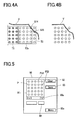
For instance, the case where an irradiation pattern of 5×5 spots is selected for irradiating a laser beam to a wide range of eye fundus is assumed. After termination of laser irradiation to a region T1, when a laser beam is to be irradiated to an adjacent region T2 according to the 5×5 irradiation pattern as shown in FIG. 4A, a part of the spots, i.e., spots S14 and S25, are likely to fall on a blood vessel V. For avoiding laser irradiation to the blood vessel V, when a 4×4 pattern is selected and a laser beam is irradiated to a region T2 a, a remaining part of the region T2 has to undergo laser irradiation of another pattern or each one spot as shown in FIG. 4B. These works are troublesome for an operator and lower treatment efficiency. Even if an apparatus includes a function of freely designing spot positions according to a treatment area, it takes time and labor to design all spots from first to last.
When photocoagulation is to be conducted on a circular area with a predetermined diameter (e.g., an annular area centered on the macula) on the fundus, a circular arc pattern (a circular arc irradiation pattern of spots arranged in a circular arc with a predetermined curvature) is selected from the irradiation patterns stored in the memory. The laser beam of this circular arc pattern is repeated plural times to arrange the spots in a circular form. However, even when only the laser irradiation in the selected circular arc pattern is repeated plural times, the spots could not be arranged in the circular form depending on the condition and the curvature of the fundus of the patient's eye. For instance, if photocoagulation is conducted on a wide area of the fundus based on a skewed irradiation pattern because the curvature of the circular arc pattern does not conform with the curvature of the fundus, the spots are not irradiated at uniform intervals onto the fundus. If various circular arc patterns having different curvatures are stored in the memory, a selection procedure to select a circular arc pattern with a desired curvature is complex, leading to poor operationality. Even if the apparatus has the function of freely designing the spot positions, such operation needs much time and labor to design all the spots into a circular pattern with a desired curvature.
The present invention has been made to solve the above problems and has a purpose to provide an ophthalmic laser treatment apparatus capable of performing efficient and appropriate treatment by effectively utilizing previously prepared irradiation patterns.
Solution to Problem
To achieve the above purpose, one aspect of the invention provides an ophthalmic laser treatment apparatus for treating a patient's eye by irradiating a treatment laser beam thereto, comprising: an irradiation unit including a treatment laser source, and a scanner for scanning an irradiation spot of the treatment beam from the laser source onto a tissue of the patient's eye in two dimensions; a memory for storing a plurality of predetermined irradiation patterns in each of which a plurality of the irradiation spots of the treatment beam are arranged in a predetermined arrangement; an irradiation pattern selecting unit including a selection switch for inputting a signal to select a desired irradiation pattern from the irradiation patterns stored in the memory; an irradiation pattern changing unit including a change switch for inputting a signal to change a part of the arrangement of the irradiation pattern in which the irradiation spots are arranged on the basis of the selected irradiation pattern by the irradiation pattern selecting unit; and a control unit for controlling driving of the irradiation unit to sequentially irradiate the treatment beam based on the irradiation pattern changed by the irradiation pattern changing unit.
Advantageous Effects of Invention
According to the present invention, it is possible to perform efficient and appropriate treatment by effectively utilize previously prepared irradiation patterns.
BRIEF DESCRIPTION OF DRAWINGS
FIG. 1 is a schematic configuration view of optical systems and a control system in an ophthalmic laser treatment apparatus;
FIG. 2 is a perspective view of a scanner;
FIG. 3 is a view showing one example of patterns;
FIGS. 4A and 4B are explanatory views of laser irradiation in a 5×5 irradiation pattern;
FIG. 5 is a view showing an example of a screen for an irradiation pattern changing mode related to a 5×5 irradiation pattern;
FIGS. 6A and 6B are explanatory views of laser irradiation in a 3×3 irradiation pattern;
FIG. 7 is a view showing an example of a screen for an irradiation pattern changing mode related to a 3×3 irradiation pattern;
FIG. 8 is a view showing an example of a screen for a changing mode of a circular arc pattern;
FIGS. 9A and 9B are schematic explanatory views showing a state where spots in the circular arc pattern are irradiated onto a fundus; and
FIGS. 10A, 10B, and 10C are views showing an example of changing a curve (a curvature) of a circular arc pattern.
DESCRIPTION OF EMBODIMENTS
A detailed description of a preferred embodiment of the present invention will now be given referring to the accompanying drawings. FIG. 1 is a schematic configuration view showing optical systems and a control system in an ophthalmic laser treatment apparatus for performing photocoagulation treatment of a fundus, and others.
An ophthalmic laser treatment apparatus 1 roughly includes a laser source unit 10, a laser irradiation optical system 40, an observation optical system 30, an illumination optical system 60, a controller 70, and an operation unit 80. The laser source unit 10 includes a treatment laser source 11 for emitting a treatment laser beam, an aiming light source 12 for emitting a visible aiming laser beam (an aiming beam), a beam splitter (a combiner) 13 for combining the treatment laser beam and the aiming beam, and a focusing lens 14. The beam splitter 13 reflects most of the treatment laser beam and transmits a part of the aiming beam. The combined laser beam is focused by the focusing lens 14 to enter an incident end face of an optical fiber 20 for delivering the laser beam to the laser irradiation optical system 40. A first shutter 15 is placed between the laser source 11 and the beam splitter 13 to block the treatment laser beam. Further, a second shutter 16 is placed on an optical path of the aiming beam from the aiming light source 12 and the treatment laser beam from the treatment laser source 11. The second shutter 16 is a safety shutter that is closed in case an abnormality occurs, but also may be used for enabling or blocking irradiation of the aiming beam during scanning of the aiming beam. The first shutter 15 also may be used for enabling or blocking irradiation of the treatment laser beam. Each shutter may be replaced with a galvano mirror having a function of switching optical paths.
The laser irradiation optical system 40 is configured as a delivery unit (an irradiation unit) mounted in a slit lamp (not shown) in the present embodiment. A laser beam (the treatment laser beam and the aiming beam) emitted from the optical fiber 20 passes through a relay lens 41, zoom lenses 42 movable in an optical axis direction to change a spot size of the laser beam, a mirror 43, and a collimator lens 44. The laser beam then passes through a scanner 50, an objective lens 45, and a reflection mirror 49 and is irradiated onto a fundus of a patient's eye E. The scanner 50 consists of a scanning optical system including a scanner mirror for moving an irradiation direction (an irradiation position) of the laser beam in two dimensions. The scanner 50 includes a first galvano mirror (a galvano scanner) 51 and a second galvano mirror 55. The first galvano mirror 51 includes a first mirror 52 for reflecting the laser beam and an actuator 53 serving as a drive part for driving (rotating) the mirror 52. Similarly, the second galvano mirror 55 includes a second mirror 56 and an actuator 57. The laser beam having passed through each optical element of the laser irradiation optical system 40 is reflected by the reflection mirror 49 and irradiated onto the fundus which is a target plane (onto the tissues) of the eye E through a contact lens CL.
The zoom lenses 42 are held in a lens cam not shown. The lens cam is rotated by operation of an operator to move each zoom lens 42 in an optical axis direction. The positions of the zoom lenses 42 are detected by an encoder 42 a attached to the lens cam. The controller 70 receives positional information (a detection signal) of each lens from the encoder 42 a and obtains a spot size of the laser beam. The scanner 50 is controlled based on a command signal from the controller 70 to form the laser beam (the spot) in a two-dimensional pattern on the target plane. The reflection mirror 49 is connected to a mechanism (a hand-operated manipulator), not shown, which is operated by the operator, to tilt the optical axis of the laser beam in two dimensions.
The structure of the scanner 50 will be explained. FIG. 2 is a perspective view of the scanner 50. The mirror 52 is attached to the actuator 53 to swing a reflection plane in an x-direction. On the other hand, the mirror 56 is attached to the actuator 57 to swing a reflection plane in a y-direction. In the present embodiment, the rotation axis of the mirror 52 coincides with a y-axis and the rotation axis of the mirror 56 coincides with a z-axis. Further, the actuators 53 and 57 are connected to and separately driven by the controller 70. Each of the actuators 53 and 57 contains a motor and a potentiometer (both not shown). The mirrors 52 and 56 are independently rotated (swung) based on command signals from the controller 70. At that time, positional information representing how much the mirrors 52 and 56 have been rotated is transmitted from the potentiometers of the actuators 53 and 57 to the controller 70. Accordingly, the controller 70 ascertains the rotational positions of the mirrors 52 and 56 with respect to the command signals.
The observation optical system (an observation unit) 30 and the illumination optical system (an illumination unit) 60 are installed in the slit lamp. The observation optical system 30 includes an objective lens and further a variable magnification optical system (a variable magnification unit), a protection filter, erect prisms, a field diaphragm, eyepieces, and others. The illumination optical system 60 for illuminating the eye E with slit light includes an illumination light source, a condenser lens, a slit, a projection lens, and others.
To the controller 70, there are connected a memory 71, the light sources 11 and 12, the encoder 42 a, the actuators 53 and 57, the operation unit 80, and a footswitch 81 serving as a device for inputting a trigger for irradiation of the laser beam. The operation unit 80 includes a touch panel display 82 used for setting laser irradiation conditions, and changing and inputting irradiation patterns. The display 82 is provided with various panel switches (for inputting a designation signal and others) for setting parameters of the laser irradiation conditions. Further, signals are input in regard to the coordinates of the display 82, thus enabling input of a signal to designate a spot position and others. The display 82 has a graphical user interface function enabling a user to visually check and set numerical values and others. For items of the irradiation conditions, there are prepared a setting part 83 for output power of the treatment laser beam, a setting part 84 for an irradiation time (a pulse width), a setting part 85 for a halt time (a time interval of irradiation of the treatment laser beam), a setting part 86 for irradiation patterns of the treatment laser beam (arrangement patterns of spot positions of the treatment laser beam to be formed on the target plane), a mode setting part 87 (a mode selector) for setting an aiming mode, a details setting switch 88, a Menu switch 82 a for calling up other setting parts and others, etc. With the mode setting part 87, a plurality of aiming modes is selectively set.
At the touch of each item on the display 82, numeral values can be set. For instance, when an operator touches the switch 86 a, selectable options are displayed in a pull-down menu. When the operator chooses a numeral value from the options, a set value in that item is determined. A plurality of irradiation patterns (or scanning patterns) is previously prepared to be selectable by the operator on the display 82. As the irradiation patterns prepared by an apparatus manufacturer, for example, there are a pattern of spots arranged in a square matrix of 2×2, 3×3, 4×4 or other (a square pattern), a pattern of spots arranged in a circular arc form (a circular arc pattern), a pattern of spots arranged in an outer circumferential direction and an inner circumferential direction to form a fan-like form (a fan-like pattern), a pattern of spots arranged in a circular form (a circular pattern), a divisional pattern of the circular pattern (a circular divisional pattern), a linear pattern of spots arranged in a linear form, and other patterns. They are stored in the memory 71. The irradiation pattern is selectable from the plurality of irradiation patterns stored in the memory 71 by use of the switch 86 a on the setting part 86. A selected irradiation pattern is displayed on the screen of the setting part 86. Further, the information of the spot size of the laser beam changed by movement of the zoom lenses 42 is displayed on the display 82.
When the footswitch 81 is pressed down by the operator, the controller 70 irradiates the laser beam based on the settings of various parameters to form a pattern of the treatment laser beam on the target plane. Specifically, the controller 70 controls the light source 11 and controls the scanner 50 based on the set pattern to form the pattern of the treatment laser beam on the target plane (the fundus).
FIG. 3 shows one example of the patterns of spot positions. As shown in the figure, this pattern is configured by arranging spots S in a 3×3 square matrix. Herein, the spots S represent both the aiming beam and the treatment laser beam. Based on such pattern, the treatment laser beam and the aiming beam are scanned by the scanner 50 to form the pattern on the target plane. The spot S starts to be irradiated from a start position SP and is scanned toward an end position GP in two dimensions. In the present embodiment, as indicated by arrows in the figure, the laser beam is scanned to sequentially move from one to adjacent spots S so as to enable movement between spots S as efficient as possible.
The interval between the spots S can be arbitrarily set in a range from 0.5 to 2 times the spot diameter by use of the spot interval setting part 89 on the display 82. In the case of the square pattern shown in FIG. 3, the spots S are arranged at equal intervals in vertical and horizontal directions.
In the apparatus configured as above, treatment operations by irradiating the treatment laser beam will be explained below. This apparatus is provided with a pattern changing function of changing a part of arrangement of the irradiation pattern in which the spots are arranged on the basis of an irradiation pattern selected by the switch 86 a or changing the shape of spot arrangement. As an example of the pattern changing function of the present apparatus, a pattern changing function of changing a part of the arrangement of the irradiation pattern in which the spots are arranged on the basis of the irradiation pattern is first explained, in which one or some spots are deleted from or added to the spots in the selected irradiation pattern. Prior to a surgical operation, conditions for the operation are set. For panretinal photocoagulation treatment, it is assumed that a spot size of the treatment laser beam is set to 200 μm and a 5×5 square pattern is selected as the irradiation pattern in advance, respectively.
The operator observes the fundus illuminated by illumination light from the illumination optical system 60, through the observation optical system 30, and also observes the spot position of the irradiated aiming beam, and moves the slit lamp (including the observation optical system 30 and the illumination optical system 60) containing the laser irradiation optical system 40 with respect to the eye E to aim the beam to a treatment area. During aiming, the aiming light source 12 and the scanner 50 are controlled to operate based on the selected irradiation pattern so that the operator observes the spot position in the irradiation pattern by visual persistence of the aiming beam. Specifically, at each spot position, the driving of the galvano mirrors 51 and 55 of the scanner 50 is stopped and the aiming beam is irradiated with a pulse width of constant time. During movement of the spot to a next position, the aiming beam is not irradiated. If the speed (cycle) of one scan to each spot position is higher than the visual persistence time of a human eye, all the spots are simultaneously observed by the operator. If the speed of one scan is slower than the visual persistence time, all the spots are not simultaneously observed. Thus, the operator can identify the irradiation order of the spots.
After the aiming beam is aligned with the treatment area by the operator who observes the aiming beam, irradiation of the treatment laser beam is started upon input of a trigger signal from the footswitch 81. At each spot position, the driving of the galvano mirrors 51 and 55 is stopped and the treatment laser source 11 is driven to irradiate the treatment laser beam for a set irradiation time. During movement of the spot, the emission of the laser beam from the treatment laser source 11 is stopped. The driving of the scanner 50 and the driving of the treatment laser source 11 are controlled based on the irradiation pattern, thereby sequentially irradiating the treatment laser beam to each spot position.
The operator moves the slit lamp installed with the laser irradiation optical system 40 or moves the reflection mirror 49 to sequentially move the irradiation region of the 5×5 spot pattern with respect to the treatment area on the fundus and performs laser irradiation. In the course of this treatment, such a relatively wide irradiation region for the 5×5 spot pattern may fall on a portion (a thick blood vessel or others) that should not undergo laser irradiation. This case is exemplified in FIG. 4A. Specifically, after the termination of laser irradiation to the region T1, when the aiming beam is aimed at the adjacent region T2, a part of the spots, i.e., spots S14 and S25, fall on the blood vessel V. To avoid this, it is conceivable to select a 4×4 irradiation pattern or others from the irradiation patterns stored in the memory 71 and perform laser irradiation to the region T2 a. However, it takes time and labor to conduct laser irradiation to the remaining part of the region T2, leading to poor efficiency.
In this case, therefore, the pattern changing function of deleting or adding one or some spots from/to the spots in the selected pattern is used. When a spot deletion/addition mode is selected by the “Menu” switch 82 a on the display 82, the screen of the display 82 is changed to a screen 90 shown in FIG. 5. In an indication part 91, spots P in a currently selected irradiation pattern are graphically displayed. When a spot position(s) is touched on the screen of the indication part 91, the position(s) in which the spot(s) is to be deleted or added is designated. In the present apparatus, specifically, a touch panel function of the display 82 is used as a spot position designating device (a change signal input device). Instead of the touch panel function, the position designating device also may be configured as a switch. In this case, a cursor appearing on the screen is moved to a desired position and this position is designated by the switch.
In the example shown in FIG. 5, when spot positions P14 and P25 corresponding to the spots S14 and S25 in FIG. 4A are designated, these spots are caused to disappear. Thus, the irradiation pattern is changed, so that the aiming beam and the treatment laser beam are not irradiated to the positions from which the spots deleted. The changed irradiation pattern is stored in a temporary storage area of the memory 71. When the spot positions P14 and P25 from which the spots have disappeared are designated again, these spots are displayed again on the screen.
The scanner 50 and the aiming light source 12 are driven based on the changed irradiation pattern, thereby irradiating the spot of the aiming beam in the changed pattern as shown in FIG. 4B. When a trigger signal is inputted by the foot switch 81, the treatment laser source 11 is caused to emit the treatment laser beam and simultaneously the scanner 50 is activated based on the changed irradiation pattern, thereby sequentially irradiating the treatment laser beam onto the fundus. Specifically, the driving of the treatment laser source 11 and the scanner 50 is controlled to perform laser irradiation by skipping the spots S14 and S25 in FIG. 4A.
In FIG. 5, when a signal is inputted by a “Clear” switch 92, the irradiation pattern changed on the indication part 91 is cleared and returned to the original 5×5 irradiation pattern. Accordingly, for a next region, laser irradiation can be performed easily in the originally selected pattern. As an alternative, it may be arranged to clear the irradiation pattern temporarily stored in the memory 71 after the laser irradiation is executed by input of the trigger signal, and display the initial 5×5 irradiation pattern again.
On the other hand, an example of adding spot(s) to the selected irradiation pattern is explained below. For instance, it is assumed that a 3×3 spot pattern is selected from the irradiation patterns stored in the memory 71. When the 3×3 spot pattern is aligned with a region T3 close to the blood vessel V as shown in FIG. 6A, next 3×3 spots for a region T4 adjacent to the region T3 are likely to fall on the blood vessel V due to its state. In this case, it takes time and labor to individually irradiate the laser beam on each of spot positions S35 and S45 in the region T4. Therefore, the pattern changing function of adding spot(s) is used.
FIG. 7 is a view showing an example of a changed screen for the irradiation pattern changing mode in the case of the 3×3 spot irradiation pattern. In the indication part 91, circular spots P representing the currently selected 3×3 irradiation pattern is graphically displayed. Around the 3×3 spots P, cross marks M are displayed to represent spot positions in which spots can be added. Each cross mark M is displayed in a position determined according to an arrangement rule of spots in the selected irradiation pattern (i.e., in a position based on the arrangement rule). In this example, spots can be added up to the 5×5 square arrangement. The maximum number of addable spots is determined based on a relationship between the setting information of the spot size determined by movement of the zoom lenses 42, the setting information of spot intervals determined by the spot interval setting part 89, and a maximum scannable range.
On the screen of the indication part 91 in FIG. 7, when spot positions M35 and M45 are designated at the touch thereof, marks M located in those positions are changed to the circular marks representing the spots P. Thus, the irradiation pattern of the spot positions is changed (a change signal in inputted). The changed irradiation pattern is stored in the temporary storage area of the memory 71. The added spots P are determined according to the arrangement rule of the initially selected irradiation pattern of 3×3. In this example, specifically, the positions of additional spots are determined in a grid arrangement extending from the 3×3 pattern. It is to be noted that the additional spot position(s) is determined by snapping a position designated at the touch of the screen to a position near the touched position and defined by the arrangement rule. When the signal is inputted by the “Clear” switch 92, the irradiation pattern changed on the indication part 91 is cleared and the initially selected pattern is displayed again.
The scanner 50 and the aiming light source 12 are activated based on the changed irradiation pattern. Accordingly, the spots are additionally observed in the spot positions S35 and S45 as well as the 3×3 spots in the region T3 as shown in FIG. 6B. When the trigger signal is inputted, the treatment laser source 11 is caused to emit the treatment laser beam and the scanner 50 is activated based on the changed irradiation pattern, thereby sequentially irradiating the treatment laser beam to the spot positions in FIG. 6B. It is therefore possible to efficiently perform treatment according to the treatment area.
As above, since the irradiation pattern is changed by deleting or adding one or some spots from/to the previously prepared irradiation pattern, the treatment can be efficiently performed and the time needed for the surgical operation can be shortened. Since the previously prepared patterns are utilized, the irradiation patterns can be set more efficiently as compared with the case of designing all spot positions from first to last. Both deletion and addition of spot(s) can be applied to the selected pattern.
The irradiation pattern changed as above can be additionally stored at the press of the switch 93 into the memory 71 as one of the irradiation patterns selectable by the switch 86 a. When the changed irradiation pattern is to be utilized again, the time and trouble of creating the irradiation pattern by deleting and/or adding the spot(s) as mentioned above.
As an example of the pattern changing function of changing the shape of spot arrangement with respect to the irradiation pattern selected by the switch 86 a, a pattern changing function of changing a curve (a curvature) of the selected circular arc pattern will be explained below. Prior to a surgical operation, conditions for the operation are set. For panretinal photocoagulation treatment, it is assumed that a spot size of the treatment laser beam is set to 200 μm and also a circular arc pattern consisting of spots arranged in a circular arc form is selected as the irradiation pattern in advance, respectively.
FIG. 8 shows an example of a screen appearing on the display 82 when the circular arc pattern is selected by the switch 86 a and the circular pattern changing mode is selected by the “Menu” switch 82 a. In an indication part 100, spots P in the currently selected circular arc pattern are graphically displayed. When this circular arc pattern is to be rotated by a desired rotation angle, a signal representing the rotation angle is inputted by switches 101 a and 101 b. The circular arc pattern is rotated clockwise by the switch 101 a and counterclockwise by the switch 101 b. The signal input to rotate the circular arc pattern may be conducted by use of a touch function. For instance, when the operator touches and drags one spot P in the irradiation pattern displayed on the indication part 100 in a desired direction to rotate the irradiation pattern, the spots P are rotated relative to the center of the circular arc and a signal representing the rotation angle is inputted (the rotation angle is determined).
FIG. 9A is a schematic explanatory view showing a state where spots (an aiming beam) of a circular arc pattern are irradiated to a fundus F. For photocoagulation treatment, the spots are irradiated in a circle centered on a center CO1 (e.g., a central fovea) of the fundus F. In FIG. 9A, a circular arc pattern Ar1 is selected by the switch 86 a and the curve of this pattern Ar1 is along a circle R1 with a radius r1 from the center CO1. When the circular arc pattern Ar1 is to be rotated, a signal representing a rotation angle is inputted by the switches 101 a and 101 b, thereby rotating this pattern Ar1 along the circle R1. In FIG. 9A, the curve of the pattern Ar1 is along the circle R1 with the radius r1 from the center C01. Accordingly, rotation of the pattern Ar1 enables the laser beam to be irradiated as spots arranged in the circle R1 with the radius r1.
However, when treatment is to be performed by arranging the spots in a circle R2 with a larger radius r2 than the radius r1, this treatment could not be conducted by use of the selected circular arc pattern Ar1. In this case, even when the pattern Ar1 is rotated, each spot is not arranged just on the circle R2. Thus, even if the laser beam is irradiated in the circular arc pattern Ar1 as it is, the treatment that arranges spots at equal intervals could not be performed. For photocoagulation on a wide area such as panretinal photocoagulation treatment (PRT) and others, preferably, a treatment laser beam is irradiated so as to arrange spots (coagulation spots) at equal intervals.
In the above case, the pattern changing function of changing the curve of a circular arc of a selected circular arc pattern is used. In FIG. 8, when switches 102 a and 102 b are operated, the curve of the circular arc Ar on which the spots P are arranged is changed on the indication part 100. In other words, a signal to change a curve of a circular arc pattern, which is a signal to change the irradiation pattern, is inputted by the operation of the switches 102 a and 102 b. The switch 102 a is used to change the curve of the circular arc Ar to have a smaller diameter and the switch 102 b is used to change the curve of the circular arc Ar to have a larger diameter. At that time, even when the curve of the circular arc Ar is changed, the spot interval D is set by the controller 70 so as to approximately coincide with a previously set value. This enables laser irradiation of the spots arranged at equal intervals.
The operator operates the switches 102 a and 102 b for change of curve, adjusts the curve of the circular arc pattern while observing the aiming beam scanned based on the irradiation pattern (a pattern on the fundus), and changes to a circular arc pattern Ar2 so as to coincide with the circle R2 of a treatment area according to the curve (the curvature) of the fundus as shown in FIG. 9B. Accordingly, it is easy for the operator to set the irradiation pattern while observing the aiming beam in real time. Since the rotation angle of the circular arc pattern Ar2 is set by the switches 101 a and 101 b, the spots in the pattern Ar2 can be arranged along the circle R2 of the treatment area. Positioning of the pattern Ars in rightward/leftward and upward/downward directions can be performed by moving the slit lamp including the optical systems or two-dimensionally tilting the reflection mirror 49 by a manipulator.
Changing the curve of the circular arc pattern may be performed on the indication part 100 by the touch panel function of the display 82, instead of using the switches 102 a and 102 b. For instance, as shown in FIG. 10A, a center spot S3 is touched and dragged upwards or downwards with respect to the displayed spots in the initially selected circular arc pattern, thereby changing a curve (a curvature) Ac1 of the circular arc pattern. As the curve changes, the arrangement form of the spots is changed. When the spot S3 is dragged downwards, as shown in FIG. 10B, the curve Ac1 is changed to a gentler curve Ac1. When the spot S3 is dragged upwards, as shown in FIG. 10C, the curve Ac1 is changed to a sharper curve Ac3. It is to be noted that the curve of the circular arc pattern may be changed to an elliptic form by dragging. Touching and dragging a leftmost spot S1 or a rightmost spot S5 in FIG. 10A can also freely change the curve. As above, the use of the touch function of the display 82 allows free change of the curve (the curvature) of the circular arc pattern. In the case where the curve of the circular arc pattern is changed as above, the arrangement of the spots S is set by the controller 70 so that the spot intervals D between the spots S are maintained as (almost equal to) a value set by the spot interval setting part 89. This enables irradiation of the laser beam with the uniform spot arrangement.
It is convenient to use the curve changing function for the circular arc pattern in combination with the aforementioned pattern changing function of deleting or adding the spot(s). For instance, when the circular arc pattern Ar2 is rotated to arrange new sports in a position continuous or adjacent to the previous spots along the circle R2 or an initially or previously irradiated area as shown in FIG. 9B, if one or some of the new spots are likely to overlap the previous spot(s), the pattern is changed by deleting the spot(s) which are likely to overlap the previous spot(s). On the other hand, if one or some spots are short when the circular arc pattern Ar2 is rotated to be continuous with another pattern Ar2, the pattern is changed by adding one or some spots.
Further, in the similar manner to the above case for deletion/addition of spot(s), the changed circular arc pattern can be additionally stored at the press of the switch 93 into the memory 71 as one of the irradiation patterns selectable by the switch 86 a. When the changed pattern is to be utilized again, it is therefore possible to save the time and trouble of creating the changed irradiation pattern.
As above, treatment can be performed by setting the circular arc pattern can according to the curved target plane (herein, the fundus F). Accordingly, the spots of the treatment laser beam can be equally spaced over the wide range of the fundus. This makes it possible to effectively conduct treatment such as photocoagulation. Since the apparatus is configured to change the curve of the previously prepared circular arc pattern, there is no need to design the circular arc pattern for each patient's eye, resulting in improved efficiency in surgical operations. In the above embodiment, the circular arc pattern is explained as the pattern consisting of the spots arranged in a line. This includes patterns (a fan-like pattern, a circular segmental pattern) consisting of spots arranged in plural circular-arc lines. The above function of changing the circular patterns may be effectively applied to these patterns.
The present invention may be embodied in other specific forms without departing from the essential characteristics thereof. For instance, the scanner 50 may include a member for e.g. tilting a single mirror in x- and y-directions. As an alternative, scanning of a laser beam or the like may be conducted by tilting a lens.
REFERENCE SIGNS LIST
  • 1 Ophthalmic laser treatment apparatus
  • 10 Laser source unit
  • 20 Optical fiber
  • 30 Observation optical system
  • 40 Laser irradiation optical system
  • 50 Scanner
  • 60 Illumination optical system
  • 70 Controller
  • 80 Operation unit
  • 90 Screen
  • 100 Indication part

Claims (2)

The invention claimed is:
1. An ophthalmic laser treatment apparatus for treating a patient's eye by irradiating a treatment laser beam thereto, comprising:
an irradiation unit including a treatment laser source, and a scanner configured to scan an irradiation spot of the treatment laser beam from the laser source onto a tissue of the patient's eye in two dimensions;
a memory configured to store a plurality of predetermined irradiation patterns in each of which a plurality of the irradiation spots of the treatment laser beam are arranged in a predetermined arrangement;
an irradiation pattern selecting unit including a selection switch configured to input a signal to select a desired irradiation pattern from the irradiation patterns stored in the memory;
an irradiation pattern changing unit including a touch panel configured to input a signal to change a part of the arrangement of the irradiation pattern in which the irradiation spots are arranged on the basis of the selected irradiation pattern by the irradiation pattern selecting unit;
a control unit configured to control driving of the irradiation unit to sequentially irradiate the treatment laser beam based on the irradiation pattern changed by the irradiation pattern changing unit; and
an aiming light source designed to emit an aiming beam, wherein
the irradiation pattern is configured to be changed during a surgical operation,
the control unit is configured to display the currently selected irradiation pattern on the touch panel,
when the irradiation pattern is changed, the control unit is configured to irradiate an aiming beam based on the changed irradiation pattern,
when a trigger signal to irradiate the treatment laser beam is inputted, the control unit is configured to irradiate the treatment laser beam based on the changed irradiation pattern,
when a signal to add a spot is input via the touch panel, the control unit is configured to execute an arrangement rule of irradiation spots in the selected irradiation pattern and add a spot in the selected irradiation pattern based on the arrangement rule, and
when a signal to delete a spot is input, the control unit is configured to delete the spot from the selected irradiation pattern based on the input signal.
2. A method of using an ophthalmic laser treatment apparatus for treating a patient's eye by irradiating a treatment laser beam thereto, comprising the steps of:
scanning with a scanner an irradiation spot of the treatment laser beam from a treatment laser source of an irradiation unit onto a tissue of the patient's eye in two dimensions;
storing on a memory a plurality of predetermined irradiation patterns in each of which a plurality of the irradiation spots of the treatment laser beam are arranged in a predetermined arrangement;
inputting a signal by a selection switch of an irradiation pattern selecting unit to select a desired irradiation pattern from the irradiation patterns stored in the memory;
inputting a signal on a touch panel of an irradiation pattern changing unit to change a part of the arrangement of the irradiation pattern in which the irradiation spots are arranged on the basis of the selected irradiation pattern by the irradiation pattern selecting unit;
driving the irradiation unit controlled by a control unit to sequentially irradiate the treatment laser beam based on the irradiation pattern changed by the irradiation pattern changing unit; and
emitting an aiming beam of an aiming light source, wherein
the irradiation pattern is changed during a surgical operation,
the control unit displays the currently selected irradiation pattern on the touch panel,
when the irradiation pattern is changed, the control unit irradiates an aiming beam based on the changed irradiation pattern,
when a trigger signal to irradiate the treatment laser beam is inputted, the control unit irradiates the treatment laser beam based on the changed irradiation pattern,
when a signal to add a spot is input via the touch panel, the control unit executes an arrangement rule of irradiation spots in the selected irradiation pattern and adds a spot in the selected irradiation pattern based on the arrangement rule, and
when a signal to delete a spot is input, the control unit deletes the spot from the selected irradiation pattern based on the input signal.
US13/073,217 2010-03-31 2011-03-28 Ophthalmic laser treatment apparatus Active 2033-08-24 US9050170B2 (en)

Priority Applications (1)

Application Number Priority Date Filing Date Title
US14/703,275 US9308129B2 (en) 2010-03-31 2015-05-04 Ophthalmic laser treatment apparatus

Applications Claiming Priority (2)

Application Number Priority Date Filing Date Title
JP2010084684A JP5601610B2 (en) 2010-03-31 2010-03-31 Ophthalmic laser treatment device
JP2010-084684 2010-03-31

Related Child Applications (1)

Application Number Title Priority Date Filing Date
US14/703,275 Division US9308129B2 (en) 2010-03-31 2015-05-04 Ophthalmic laser treatment apparatus

Publications (2)

Publication Number Publication Date
US20110245815A1 US20110245815A1 (en) 2011-10-06
US9050170B2 true US9050170B2 (en) 2015-06-09

Family

ID=44117381

Family Applications (2)

Application Number Title Priority Date Filing Date
US13/073,217 Active 2033-08-24 US9050170B2 (en) 2010-03-31 2011-03-28 Ophthalmic laser treatment apparatus
US14/703,275 Active US9308129B2 (en) 2010-03-31 2015-05-04 Ophthalmic laser treatment apparatus

Family Applications After (1)

Application Number Title Priority Date Filing Date
US14/703,275 Active US9308129B2 (en) 2010-03-31 2015-05-04 Ophthalmic laser treatment apparatus

Country Status (3)

Country Link
US (2) US9050170B2 (en)
EP (1) EP2371327B1 (en)
JP (1) JP5601610B2 (en)

Families Citing this family (11)

* Cited by examiner, † Cited by third party
Publication number Priority date Publication date Assignee Title
US10238541B2 (en) 2011-10-19 2019-03-26 Iridex Corporation Short duration pulse grid pattern laser treatment and methods
US20130110093A1 (en) 2011-10-19 2013-05-02 Iridex Corporation Slit lamp grid pattern laser treatment adapter
US9849034B2 (en) * 2011-11-07 2017-12-26 Alcon Research, Ltd. Retinal laser surgery
JP5956884B2 (en) * 2012-09-13 2016-07-27 株式会社トプコン Laser therapy device
CN104685393A (en) 2012-09-24 2015-06-03 艾瑞黛克斯公司 Hybrid device identifier
JP6040688B2 (en) * 2012-09-28 2016-12-07 株式会社ニデック Ophthalmic laser treatment device
KR101421654B1 (en) * 2012-11-13 2014-07-22 주식회사 루트로닉 Apparatus for treating ocular and control method thereof
JP6236882B2 (en) * 2013-06-03 2017-11-29 株式会社ニデック Laser therapy device
JP6937564B2 (en) * 2016-11-08 2021-09-22 株式会社トプコン Ophthalmic laser system
JP7427891B2 (en) * 2019-09-17 2024-02-06 株式会社ニデック Laser treatment device and laser treatment control program
US20240099889A1 (en) * 2022-09-28 2024-03-28 Nidek Co., Ltd. Ophthalmic laser treatment device

Citations (21)

* Cited by examiner, † Cited by third party
Publication number Priority date Publication date Assignee Title
JPH02161930A (en) 1988-12-16 1990-06-21 Topcon Corp Laser scanning type light freezing device
US5906609A (en) 1997-02-05 1999-05-25 Sahar Technologies Method for delivering energy within continuous outline
US5938657A (en) 1997-02-05 1999-08-17 Sahar Technologies, Inc. Apparatus for delivering energy within continuous outline
WO2000013629A1 (en) 1998-09-04 2000-03-16 Sunrise Technologies International, Inc. Radiation treatment system and methods for correcting vision
JP2001149403A (en) 1999-11-26 2001-06-05 Nidek Co Ltd Photocoagulator
EP1210915A2 (en) 2000-12-01 2002-06-05 Nidek Co., Ltd. Laser treatment apparatus
US20020099363A1 (en) 2001-01-23 2002-07-25 Woodward Benjamin W. Radiation treatment system and method of using same
JP2002224154A (en) 2001-02-01 2002-08-13 Nidek Co Ltd Laser treatment device
US6585725B1 (en) 1999-04-20 2003-07-01 Nidek Co., Ltd. Laser irradiation method for laser treatment and laser treatment apparatus
US20040073200A1 (en) 2002-02-12 2004-04-15 Visx,Incorporated Flexible scanning beam imaging system
WO2005065116A2 (en) 2003-12-24 2005-07-21 The Board Of Trustees Of The Leland Stanford Junior University Patterned laser treatment of the retina
US7173745B2 (en) 2001-04-27 2007-02-06 Q-Vis Limited Optical beam delivery configuration
WO2007035855A2 (en) 2005-09-19 2007-03-29 Optimedica Corporation System and method for generating treatment patterns
US20070121069A1 (en) 2005-11-16 2007-05-31 Andersen Dan E Multiple spot photomedical treatment using a laser indirect ophthalmoscope
WO2007082102A2 (en) 2006-01-12 2007-07-19 Optimedica Corporation Optical delivery systems and methods of providing adjustable beam diameter, spot size and/or spot shape
US20080015553A1 (en) 2006-07-12 2008-01-17 Jaime Zacharias Steering laser treatment system and method of use
WO2008112292A1 (en) 2007-03-13 2008-09-18 Optimedica Corporation Apparatus for creating ocular surgical and relaxing incisions
US20090093798A1 (en) * 2007-10-05 2009-04-09 Steven Thomas Charles Semi-automated ophthalmic photocoagulation method and apparatus
CN101553280A (en) 2005-09-19 2009-10-07 眼科医疗公司 System and method for generating treatment patterns
US20110178512A1 (en) 2005-01-10 2011-07-21 Blumenkranz Mark S Method and apparatus for patterned plasma-mediated laser trephination of the lens capsule and three dimensional phaco-segmentation
US20110202046A1 (en) 2010-01-22 2011-08-18 Optimedica Corporation Method and apparatus for automated placement of scanned laser capsulorhexis incisions

Family Cites Families (2)

* Cited by examiner, † Cited by third party
Publication number Priority date Publication date Assignee Title
US6099522A (en) * 1989-02-06 2000-08-08 Visx Inc. Automated laser workstation for high precision surgical and industrial interventions
DE102009021604A1 (en) * 2009-05-15 2010-11-18 Carl Zeiss Meditec Ag Method for marking coagulation sites on a retina and system for coagulation of the retina

Patent Citations (27)

* Cited by examiner, † Cited by third party
Publication number Priority date Publication date Assignee Title
JPH02161930A (en) 1988-12-16 1990-06-21 Topcon Corp Laser scanning type light freezing device
US5906609A (en) 1997-02-05 1999-05-25 Sahar Technologies Method for delivering energy within continuous outline
US5938657A (en) 1997-02-05 1999-08-17 Sahar Technologies, Inc. Apparatus for delivering energy within continuous outline
JP2002524144A (en) 1998-09-04 2002-08-06 サンライズ テクノロジィース インターナショナル インコーポレイテッド Radiotherapy systems and methods for correcting vision
WO2000013629A1 (en) 1998-09-04 2000-03-16 Sunrise Technologies International, Inc. Radiation treatment system and methods for correcting vision
US6585725B1 (en) 1999-04-20 2003-07-01 Nidek Co., Ltd. Laser irradiation method for laser treatment and laser treatment apparatus
JP2001149403A (en) 1999-11-26 2001-06-05 Nidek Co Ltd Photocoagulator
EP1210915A2 (en) 2000-12-01 2002-06-05 Nidek Co., Ltd. Laser treatment apparatus
US20020099363A1 (en) 2001-01-23 2002-07-25 Woodward Benjamin W. Radiation treatment system and method of using same
JP2002224154A (en) 2001-02-01 2002-08-13 Nidek Co Ltd Laser treatment device
US6673061B2 (en) 2001-02-01 2004-01-06 Nidek Co., Ltd. Laser treatment apparatus
US7173745B2 (en) 2001-04-27 2007-02-06 Q-Vis Limited Optical beam delivery configuration
US20040073200A1 (en) 2002-02-12 2004-04-15 Visx,Incorporated Flexible scanning beam imaging system
WO2005065116A2 (en) 2003-12-24 2005-07-21 The Board Of Trustees Of The Leland Stanford Junior University Patterned laser treatment of the retina
JP2006524515A (en) 2003-12-24 2006-11-02 ザ・ボード・オブ・トラスティーズ・オブ・ザ・レランド・スタンフォード・ジュニア・ユニバーシティ Retina patterned laser treatment method
US20110178512A1 (en) 2005-01-10 2011-07-21 Blumenkranz Mark S Method and apparatus for patterned plasma-mediated laser trephination of the lens capsule and three dimensional phaco-segmentation
JP2009514564A (en) 2005-09-19 2009-04-09 オプティメディカ・コーポレイション System and method for generating treatment patterns
US20070129775A1 (en) 2005-09-19 2007-06-07 Mordaunt David H System and method for generating treatment patterns
CN101553280A (en) 2005-09-19 2009-10-07 眼科医疗公司 System and method for generating treatment patterns
WO2007035855A2 (en) 2005-09-19 2007-03-29 Optimedica Corporation System and method for generating treatment patterns
US20070121069A1 (en) 2005-11-16 2007-05-31 Andersen Dan E Multiple spot photomedical treatment using a laser indirect ophthalmoscope
WO2007082102A2 (en) 2006-01-12 2007-07-19 Optimedica Corporation Optical delivery systems and methods of providing adjustable beam diameter, spot size and/or spot shape
US20070189664A1 (en) 2006-01-12 2007-08-16 Andersen Dan E Optical delivery systems and methods of providing adjustable beam diameter, spot size and/or spot shape
US20080015553A1 (en) 2006-07-12 2008-01-17 Jaime Zacharias Steering laser treatment system and method of use
WO2008112292A1 (en) 2007-03-13 2008-09-18 Optimedica Corporation Apparatus for creating ocular surgical and relaxing incisions
US20090093798A1 (en) * 2007-10-05 2009-04-09 Steven Thomas Charles Semi-automated ophthalmic photocoagulation method and apparatus
US20110202046A1 (en) 2010-01-22 2011-08-18 Optimedica Corporation Method and apparatus for automated placement of scanned laser capsulorhexis incisions

Non-Patent Citations (11)

* Cited by examiner, † Cited by third party
Title
Aug. 13, 2013 Office Action issued in U.S. Appl. No. 13/073,256.
Aug. 19, 2013 Office Action issued in U.S. Appl. No. 13/073,278.
Dec. 13, 2012 Office Action issued in U.S. Appl. No. 13/073,278.
European Search Report issued in European Patent Application No. 11160163.9 mailed Aug. 8, 2011.
European Search Report issued in European Patent Application No. 11160416.1 mailed Jul. 13, 2011.
Feb. 12, 2015 Office Action issued in U.S. Appl. No. 13/073,256.
Jan. 2, 2013 Office Action issued in U.S. Appl. No. 13/073,256.
Japanese Office Action dated Feb. 4, 2014 issued in Japanese Patent Application No. 2010-084684 (with partial translation).
Jun. 5, 2014 Office Action issued in U.S. Appl. No. 13/073,256.
U.S. Appl. No. 13/073,256, filed Mar. 28, 2011 in the name of Abe.
U.S. Appl. No. 13/073,278, filed Mar. 28, 2011 in the name of Yokosuka et al.

Also Published As

Publication number Publication date
US20110245815A1 (en) 2011-10-06
EP2371327B1 (en) 2013-01-16
US20150230986A1 (en) 2015-08-20
JP2011212349A (en) 2011-10-27
US9308129B2 (en) 2016-04-12
EP2371327A1 (en) 2011-10-05
JP5601610B2 (en) 2014-10-08

Similar Documents

Publication Publication Date Title
US9308129B2 (en) Ophthalmic laser treatment apparatus
US9724236B2 (en) Ophthalmic laser treatment apparatus
JP5578550B2 (en) Ophthalmic laser treatment device
US8512319B2 (en) Ophthalmic laser treatment apparatus
EP1926446B1 (en) System and method for generating treatment patterns
US9901485B2 (en) Ophthalmic laser treatment apparatus
JP5627898B2 (en) Ophthalmic laser treatment device
JP2010158331A (en) Ophthalmic laser treatment apparatus
JP6830810B2 (en) Ophthalmic laser system
JP5562713B2 (en) Ophthalmic laser treatment device
CN101553280A (en) System and method for generating treatment patterns
EP0960609B1 (en) Laser treatment apparatus
JP5928516B2 (en) Ophthalmic laser treatment device
CN210044259U (en) Laser therapeutic device
JP5800169B2 (en) Ophthalmic laser treatment device
JP7088169B2 (en) Laser treatment device for ophthalmology
JP7099848B2 (en) Ophthalmic laser system
JP2017176558A (en) Ophthalmic laser treatment apparatus
JP6972620B2 (en) Laser treatment device for ophthalmology
JP2019058577A (en) Ophthalmological laser treatment apparatus

Legal Events

Date Code Title Description
AS Assignment

Owner name: NIDEK CO., LTD., JAPAN

Free format text: ASSIGNMENT OF ASSIGNORS INTEREST;ASSIGNOR:ABE, HITOSHI;REEL/FRAME:026109/0471

Effective date: 20110314

STCF Information on status: patent grant

Free format text: PATENTED CASE

MAFP Maintenance fee payment

Free format text: PAYMENT OF MAINTENANCE FEE, 4TH YEAR, LARGE ENTITY (ORIGINAL EVENT CODE: M1551); ENTITY STATUS OF PATENT OWNER: LARGE ENTITY

Year of fee payment: 4

MAFP Maintenance fee payment

Free format text: PAYMENT OF MAINTENANCE FEE, 8TH YEAR, LARGE ENTITY (ORIGINAL EVENT CODE: M1552); ENTITY STATUS OF PATENT OWNER: LARGE ENTITY

Year of fee payment: 8