US9032071B2 - Systems and methods for representing a SAS fabric - Google Patents
Systems and methods for representing a SAS fabric Download PDFInfo
- Publication number
- US9032071B2 US9032071B2 US13/556,667 US201213556667A US9032071B2 US 9032071 B2 US9032071 B2 US 9032071B2 US 201213556667 A US201213556667 A US 201213556667A US 9032071 B2 US9032071 B2 US 9032071B2
- Authority
- US
- United States
- Prior art keywords
- sas
- devices
- directly attached
- entry point
- point switch
- Prior art date
- Legal status (The legal status is an assumption and is not a legal conclusion. Google has not performed a legal analysis and makes no representation as to the accuracy of the status listed.)
- Expired - Fee Related, expires
Links
Images


Classifications
-
- G—PHYSICS
- G06—COMPUTING; CALCULATING OR COUNTING
- G06F—ELECTRIC DIGITAL DATA PROCESSING
- G06F13/00—Interconnection of, or transfer of information or other signals between, memories, input/output devices or central processing units
- G06F13/14—Handling requests for interconnection or transfer
-
- G—PHYSICS
- G06—COMPUTING; CALCULATING OR COUNTING
- G06F—ELECTRIC DIGITAL DATA PROCESSING
- G06F13/00—Interconnection of, or transfer of information or other signals between, memories, input/output devices or central processing units
- G06F13/38—Information transfer, e.g. on bus
- G06F13/40—Bus structure
- G06F13/4004—Coupling between buses
- G06F13/4022—Coupling between buses using switching circuits, e.g. switching matrix, connection or expansion network
Definitions
- the original small computer system interface (SCSI) protocol was developed to provide a common interface that could be used across peripheral platforms and system applications. Multiple generations of the parallel SCSI protocol successively doubled bandwidths, while also increasing signal degradation, and signal skew.
- SAS Serial Attached SCSI
- the SAS architecture solves the parallel SCSI problems of bus contention, clock skew, and signal degradation at higher signaling rates, thereby providing performance headroom to meet enterprise storage needs. Further, serial attached SCSI devices provide access to multiple storage facilities over a single bus.
- FIG. 1 is a block diagram of devices in an example SAS fabric
- FIG. 2 is a block diagram of an example client and SAS switch in the SAS fabric
- FIG. 3 is a process flow diagram of a method for generating a visual representation of the SAS fabric
- FIG. 4 is a block diagram of a system for representing the SAS fabric.
- FIG. 5 is a block diagram showing a tangible, non-transitory, machine-readable medium that stores code for generating a visual representation of the SAS fabric.
- a SAS fabric represents a network of computing devices accessing storage using the SAS protocol.
- Visual representations, e.g., device trees, of a SAS fabric are useful for maintaining and administrating the SAS fabric.
- a device tree of the SAS fabric may include a large data model, which makes it impractical to store on an individual device.
- maintaining a data model of an entire SAS fabric is expensive in terms of system RAM usage, especially for a maximum configuration SAS fabric. To make it possible to see the entire SAS fabric from each SAS switch would mean maintaining a data model of N maximum configurations, which is not technically feasible, nor practical.
- a representation of the entire SAS fabric may be generated using any switch in the fabric as a single point of access. This may be done while having each SAS switch maintain a data model that meets the constraints of the typical SAS switch.
- FIG. 1 is a block diagram of devices in an example SAS fabric 100 .
- the SAS fabric 100 includes clients 102 , initiators 104 , targets 106 , and SAS switches 108 .
- the clients 102 are computing devices that read and write data, commands to, and from, targets 106 , i.e., storage devices.
- the data and commands are routed along the SAS fabric 100 in the form of packets, which are formatted according to various communication protocols.
- the clients 102 include an initiator 104 .
- the initiator 104 may be an array controller containing the ports that interface with the SAS fabric 100 .
- Clients 102 , targets 106 , and SAS switches 108 are also connected to each other via Ethernet.
- the targets 106 may include SAS hard drives and serial advanced technology attachment (SATA) hard drives, which advantageously share an electrical and physical connection interface.
- SATA serial advanced technology attachment
- the SAS switches 108 establish connections between initiators 104 , targets 106 , and other SAS switches 108 by receiving packets in one port, and routing the packets to another port based on an SAS address of the target 106 .
- the SAS switch 108 typically uses three routing methods: direct, table, and subtractive.
- the SAS switch 108 uses direct routing to forward commands and data to targets 106 that are directly attached.
- the SAS switch 108 uses table routing to forward commands and data to another SAS switch 108 or expander-based SAS device.
- the expander-based SAS device is any device that contains a SAS expander, such as a storage enclosure that contains SAS expanders.
- Connecting SAS switches together enables the creation of large SAS fabrics 100 .
- the number of initiators 104 and targets 106 in a SAS fabric 100 can be expanded merely by expanding the sizes of routing tables in the SAS switches 108 .
- the SAS switch 108 has the view of the entire SAS fabric 100 .
- maintaining such a view for large SAS fabrics may exceed the available memory on the SAS switch 108 .
- the information available from each SAS switch 108 is limited to information about the initiators 104 and targets 106 that are directly attached to the SAS switch 108 .
- Connected SAS switches are also referred to herein as trunked SAS switches.
- the example SAS fabric 100 can generate a visual representation of the entire SAS fabric 100 from the perspective of a single SAS switch 108 . This may be done while maintaining a data model on the SAS switches 108 that does not exceed typical technical, e.g., memory, constraints.
- FIG. 2 is a block diagram of an example client 102 and SAS switch 108 in the SAS fabric 100 .
- the client 102 includes initiator 104 with ports 202 .
- the client 102 also includes a web browser 204 , and device tree 206 .
- the web browser 204 queries the SAS switch 108 in an exchange that generates a visual representation of the SAS fabric 100 , e.g., device tree 206 .
- the device tree 206 represents all the devices (initiators 104 , targets 106 , SAS switches 108 ) in the SAS fabric 100 from the perspective of the queried SAS switch 108 .
- the device tree 206 may be displayed on the client 102 , and may be rendered graphically by the web browser 204 using client-side techniques such as JavaScript, dynamic hypertext markup language (DHTML), hypertext markup language version 5 (HTML5), extensible markup language (XML), and so on. It is understood that the device tree 206 is an example visual representation. However, other representations are possible in example implementations.
- client-side techniques such as JavaScript, dynamic hypertext markup language (DHTML), hypertext markup language version 5 (HTML5), extensible markup language (XML), and so on. It is understood that the device tree 206 is an example visual representation. However, other representations are possible in example implementations.
- the SAS switch 108 includes SAS switch ports 208 , a web server 210 , a data model 212 , and a device tree generator 214 .
- the web server 210 may process hypertext transfer protocol (HTTP) requests from the client 102 , or other devices in, or in communication with, the SAS fabric 100 .
- HTTP hypertext transfer protocol
- the data model 212 includes data about all of the initiators 104 and targets 106 attached directly to the SAS switch ports 208 .
- the data model 212 may also include peripheral information, such as cabling details and access information.
- the data model 212 does not model details of all of the initiators 104 and targets 106 attached to other SAS switches 108 , although some exceptions exists, such as route table information and the like.
- the data model 212 may include a directory of each SAS switch 108 in the SAS fabric 100 , and the number of hops away from this SAS switch 108 .
- a hop represents a network link disposed between the SAS switches 108 .
- the other SAS switches may be represented as stubs (not shown) within the data model 212 .
- the stubs contain the IP address of the other SAS switches 108 .
- the location of each stub in the data model 212 is related to the number of hops for the corresponding SAS switch 108 .
- the web server 210 may invoke the device tree generator 214 .
- the device tree generator 214 provides the data model 212 to the client 204 , using a data-interchange format, such as JavaScript object notation (JSON) XML, HTML5, and the like.
- JSON JavaScript object notation
- a client-side application 220 may use the data model 212 , and stubs to display the device tree 206 including the entire SAS fabric 100 .
- the client-side application 220 retrieves data models 212 from SAS switches that are not connected to the entry point.
- the entry point is the SAS switch 108 which receives the device tree request from the client 204 .
- the displayed device tree 206 is generated by combining these data models 212 .
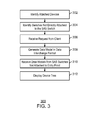
- FIG. 3 is a process flow diagram of a method 300 for generating a visual representation of the SAS fabric 100 .
- the method 300 may be performed by the client 204 and the device tree generator 214 . Further, blocks 302 - 304 are performed for each SAS switch 108 in the fabric 100 . However, blocks 306 - 320 are performed for the entry point.
- the method 300 begins at block 302 , where the device tree generator 214 identifies the devices that are directly attached to the SAS switch 108 .
- the SAS switch 108 performs Discovery for the full SAS fabric 100 . Discovery is a process whereby the device tree generator 214 crawls the full SAS fabric 100 to discover all attached devices.
- the SAS switch 108 does not record detailed device information of end devices that are not directly attached to the SAS switch 108 performing the Discovery. For example, if SAS switch # 1 performs Discovery, and determines that SAS switch # 2 has a storage enclosure with hard drives, SAS switch # 1 does not record the hard drive serial numbers. However, if SAS switch # 1 has a storage enclosure with hard drives directly connected to one of its ports, SAS switch # 1 records the hard drive serial numbers. In this way, each SAS switch 108 is merely configured with enough resources, e.g., RAM, to maintain a data model 212 of devices directly attached. Information about the SAS fabric 100 , such as IP addresses of the attached devices, may be stored in the data model 212 .
- the device tree generator 214 identifies the SAS switches 108 that are in the SAS fabric, but not directly attached to a particular SAS switch 108 .
- the IP addresses and hop distances of these “un-attached” SAS switches may be stored in the stubs of the data model 212 .
- the device tree generator 214 for the entry point receives a request for SAS fabric information from the client 204 .
- the device tree generator 214 generates the data model 212 in a data interchange format, such as JSON.
- the data interchange format may direct the client-side application 220 to generate the representation for display.
- a server device outside the SAS fabric 100 may generate the data-interchange-formatted data model 212 in response to a request from the SAS switch 106 .
- the client-side application 220 dynamically retrieves data models 212 from the SAS switches 108 that are not directly connected to the entry point. This may be done using cross-domain techniques, such as asynchronous JavaScript (AJAX).
- AJAX asynchronous JavaScript
- the client 204 displays the device tree 206 . This may be done by graphically rendering the device tree 206 , representation of the SAS fabric 100 , including all of the trunked SAS switches 108 .
- FIG. 4 is a block diagram of a system 400 for representing the SAS fabric 100 .
- the functional blocks and devices shown in FIG. 4 may comprise hardware elements, software elements, or some combination of software and hardware.
- the hardware elements may include circuitry.
- the software elements may include computer code stored as machine-readable instructions on a non-transitory, computer-readable medium.
- the functional blocks and devices of the system 400 are but one example of functional blocks and devices that may be implemented in an example. Specific functional blocks may be defined based on design considerations for a particular electronic device.
- the system 400 may include a coordinator server 402 , and a SAS fabric 404 , in communication over a network 406 .
- the coordinator server 402 may include a processor 408 , which may be connected through a bus 410 to a display 412 , a keyboard 414 , an input device 416 , and an output device, such as a printer 418 .
- the input devices 416 may include devices such as a mouse or touch screen.
- the server node 402 may also be connected through the bus 410 to a network interface card 420 .
- the network interface card 420 may connect the server 402 to the network 406 .
- the network 406 may be a local area network, a wide area network, such as the Internet, or another network configuration.
- the network 406 may include routers, switches, modems, or any other kind of interface device used for interconnection. In one example, the network 406 may be the Internet.
- the coordinator server 402 may have other units operatively coupled to the processor 412 through the bus 410 . These units may include non-transitory, computer-readable storage media, such as storage 422 .
- the storage 422 may include media for the long-term storage of operating software and data, such as hard drives.
- the storage 422 may also include other types of non-transitory, computer-readable media, such as read-only memory and random access memory.
- the storage 422 may include the machine readable instructions used in examples of the present techniques.
- the storage 422 may include SAS fabric representation generator 424 . Similar to the device tree generator 214 , the SAS fabric representation generator 424 may provide the data model 212 in an interchange data format to a client of the SAS fabric, whereby the client generates a visual representation of the SAS fabric 404 on the display 412 .
- FIG. 5 is a block diagram showing a tangible, non-transitory, machine-readable medium that stores code for generating a visual representation of an SAS fabric.
- the machine-readable medium is generally referred to by the reference number 500 .
- the machine-readable medium 500 may correspond to any typical storage device that stores computer-implemented instructions, such as programming code or the like. As shown, the machine-readable medium may be connected to a processor, over an interconnect 504 or other bus. Moreover, the machine-readable medium 500 may be included in the storage 422 shown in FIG. 4 .
- the medium 500 includes a SAS fabric representation generator 508 may store a data model representing devices directly attached to an SAS switch, and SAS switches in the SAS fabric that are not directly attached.
- the SAS fabric generator 508 provides the data model to a client that generates the visual representation.
- the data model is provided in a data interchange format.
- FIG. 5 The block diagram of FIG. 5 is not intended to indicate that the tangible, non-transitory computer-readable medium 500 is to include all of the components shown in FIG. 4 . Further, any number of additional components may be included within the tangible, non-transitory computer-readable medium 500 , depending on the details of a specific implementation.
Abstract
Description
Claims (20)
Priority Applications (1)
| Application Number | Priority Date | Filing Date | Title |
|---|---|---|---|
| US13/556,667 US9032071B2 (en) | 2012-07-24 | 2012-07-24 | Systems and methods for representing a SAS fabric |
Applications Claiming Priority (1)
| Application Number | Priority Date | Filing Date | Title |
|---|---|---|---|
| US13/556,667 US9032071B2 (en) | 2012-07-24 | 2012-07-24 | Systems and methods for representing a SAS fabric |
Publications (2)
| Publication Number | Publication Date |
|---|---|
| US20140032737A1 US20140032737A1 (en) | 2014-01-30 |
| US9032071B2 true US9032071B2 (en) | 2015-05-12 |
Family
ID=49996022
Family Applications (1)
| Application Number | Title | Priority Date | Filing Date |
|---|---|---|---|
| US13/556,667 Expired - Fee Related US9032071B2 (en) | 2012-07-24 | 2012-07-24 | Systems and methods for representing a SAS fabric |
Country Status (1)
| Country | Link |
|---|---|
| US (1) | US9032071B2 (en) |
Citations (31)
| Publication number | Priority date | Publication date | Assignee | Title |
|---|---|---|---|---|
| US6792511B2 (en) | 2002-08-16 | 2004-09-14 | Hewlett-Packard Development Company, L.P. | Dual cache module support for array controller |
| US6966003B1 (en) * | 2001-01-12 | 2005-11-15 | 3Com Corporation | System and method for switching security associations |
| US7028177B2 (en) | 2002-01-31 | 2006-04-11 | Hewlett-Packard Development Company, L.P. | Array controller ROM cloning in redundant controllers |
| US20060101171A1 (en) * | 2004-11-05 | 2006-05-11 | Grieff Thomas W | SAS expander |
| US20060194386A1 (en) | 2005-02-25 | 2006-08-31 | Dell Products L.P. | Method and apparatus for supporting port aggregation of serial attached SCSI wide ports via virtual ports |
| US20070121819A1 (en) * | 2003-12-05 | 2007-05-31 | Microsoft Corporation | System and method for media-enabled messaging having publish-and-send feature |
| US20070162592A1 (en) * | 2006-01-06 | 2007-07-12 | Dell Products L.P. | Method for zoning data storage network using SAS addressing |
| US20080028107A1 (en) * | 2006-07-28 | 2008-01-31 | Jacob Cherian | System and method for automatic reassignment of shared storage on blade replacement |
| US20080126857A1 (en) * | 2006-08-14 | 2008-05-29 | Robert Beverley Basham | Preemptive Data Protection for Copy Services in Storage Systems and Applications |
| US20080168374A1 (en) | 2007-01-06 | 2008-07-10 | International Business Machines Corporation | Method to manage external indicators for different sas port types |
| US20080189723A1 (en) * | 2007-02-06 | 2008-08-07 | International Business Machines Corporation | RAID Array Data Member Copy Offload in High Density Packaging |
| US20080228897A1 (en) | 2007-03-12 | 2008-09-18 | Ko Michael A | Layering serial attached small computer system interface (sas) over ethernet |
| US20100064085A1 (en) | 2008-09-05 | 2010-03-11 | Johnson Stephen B | Combining multiple SAS expanders to provide single sas expander functionality |
| US20100122107A1 (en) * | 2008-11-13 | 2010-05-13 | International Business Machines Corporation | Physical Interface Macros (PHYS) Supporting Heterogeneous Electrical Properties |
| US20110145452A1 (en) * | 2009-12-16 | 2011-06-16 | Lsi Corporation | Methods and apparatus for distribution of raid storage management over a sas domain |
| US20110218779A1 (en) * | 2010-03-05 | 2011-09-08 | Vasant Palisetti | Identification of Critical Enables Using MEA and WAA Metrics |
| US20110246692A1 (en) * | 2010-03-31 | 2011-10-06 | International Business Machines Corporation | Implementing Control Using A Single Path In A Multiple Path Interconnect System |
| US20110283028A1 (en) * | 2010-05-13 | 2011-11-17 | International Business Machines Corporation | Implementing network manager quarantine mode |
| US20120166582A1 (en) * | 2010-12-22 | 2012-06-28 | May Patents Ltd | System and method for routing-based internet security |
| US20120284435A1 (en) * | 2011-05-03 | 2012-11-08 | Myrah Michael G | Zone group manager virtual phy |
| US20120311222A1 (en) * | 2011-06-02 | 2012-12-06 | International Business Machines Corporation | Implementing device physical location identification in serial attached scsi (sas) fabric using resource path groups |
| US20130067164A1 (en) * | 2011-09-09 | 2013-03-14 | Vinu Velayudhan | Methods and structure for implementing logical device consistency in a clustered storage system |
| US20130145064A1 (en) * | 2005-12-02 | 2013-06-06 | Branislav Radovanovic | Scalable Data Storage Architecture And Methods Of Eliminating I/O Traffic Bottlenecks |
| US8477616B1 (en) * | 2001-06-05 | 2013-07-02 | Avaya Inc. | Method for achieving high-availability of itineraries in a real-time network scheduled packet routing system |
| US20130201316A1 (en) * | 2012-01-09 | 2013-08-08 | May Patents Ltd. | System and method for server based control |
| US20130246683A1 (en) * | 2012-03-13 | 2013-09-19 | Balaji Natrajan | Sas fabric discovery |
| US20130275648A1 (en) * | 2012-04-17 | 2013-10-17 | Sohail Hameed | Determination of a zoned portion of a service delivery system |
| US8589607B1 (en) * | 2012-08-07 | 2013-11-19 | Lsi Corporation | Methods and structure for hardware management of serial advanced technology attachment (SATA) DMA non-zero offsets in a serial attached SCSI (SAS) expander |
| US20140040510A1 (en) * | 2012-07-31 | 2014-02-06 | Michael G. Myrah | Staged discovery in a data storage fabric |
| US20140040648A1 (en) * | 2012-07-31 | 2014-02-06 | Paul Miller | Power management for devices in a data storage fabric |
| US20140052845A1 (en) * | 2012-08-17 | 2014-02-20 | Vmware, Inc. | Discovery of storage area network devices for a virtual machine |
-
2012
- 2012-07-24 US US13/556,667 patent/US9032071B2/en not_active Expired - Fee Related
Patent Citations (32)
| Publication number | Priority date | Publication date | Assignee | Title |
|---|---|---|---|---|
| US6966003B1 (en) * | 2001-01-12 | 2005-11-15 | 3Com Corporation | System and method for switching security associations |
| US8477616B1 (en) * | 2001-06-05 | 2013-07-02 | Avaya Inc. | Method for achieving high-availability of itineraries in a real-time network scheduled packet routing system |
| US7028177B2 (en) | 2002-01-31 | 2006-04-11 | Hewlett-Packard Development Company, L.P. | Array controller ROM cloning in redundant controllers |
| US6792511B2 (en) | 2002-08-16 | 2004-09-14 | Hewlett-Packard Development Company, L.P. | Dual cache module support for array controller |
| US20070121819A1 (en) * | 2003-12-05 | 2007-05-31 | Microsoft Corporation | System and method for media-enabled messaging having publish-and-send feature |
| US7644168B2 (en) * | 2004-11-05 | 2010-01-05 | Hewlett-Packard Development Company, L.P. | SAS expander |
| US20060101171A1 (en) * | 2004-11-05 | 2006-05-11 | Grieff Thomas W | SAS expander |
| US20060194386A1 (en) | 2005-02-25 | 2006-08-31 | Dell Products L.P. | Method and apparatus for supporting port aggregation of serial attached SCSI wide ports via virtual ports |
| US20130145064A1 (en) * | 2005-12-02 | 2013-06-06 | Branislav Radovanovic | Scalable Data Storage Architecture And Methods Of Eliminating I/O Traffic Bottlenecks |
| US20070162592A1 (en) * | 2006-01-06 | 2007-07-12 | Dell Products L.P. | Method for zoning data storage network using SAS addressing |
| US20080028107A1 (en) * | 2006-07-28 | 2008-01-31 | Jacob Cherian | System and method for automatic reassignment of shared storage on blade replacement |
| US20080126857A1 (en) * | 2006-08-14 | 2008-05-29 | Robert Beverley Basham | Preemptive Data Protection for Copy Services in Storage Systems and Applications |
| US20080168374A1 (en) | 2007-01-06 | 2008-07-10 | International Business Machines Corporation | Method to manage external indicators for different sas port types |
| US20080189723A1 (en) * | 2007-02-06 | 2008-08-07 | International Business Machines Corporation | RAID Array Data Member Copy Offload in High Density Packaging |
| US20080228897A1 (en) | 2007-03-12 | 2008-09-18 | Ko Michael A | Layering serial attached small computer system interface (sas) over ethernet |
| US20100064085A1 (en) | 2008-09-05 | 2010-03-11 | Johnson Stephen B | Combining multiple SAS expanders to provide single sas expander functionality |
| US20100122107A1 (en) * | 2008-11-13 | 2010-05-13 | International Business Machines Corporation | Physical Interface Macros (PHYS) Supporting Heterogeneous Electrical Properties |
| US20110145452A1 (en) * | 2009-12-16 | 2011-06-16 | Lsi Corporation | Methods and apparatus for distribution of raid storage management over a sas domain |
| US20110218779A1 (en) * | 2010-03-05 | 2011-09-08 | Vasant Palisetti | Identification of Critical Enables Using MEA and WAA Metrics |
| US20110246692A1 (en) * | 2010-03-31 | 2011-10-06 | International Business Machines Corporation | Implementing Control Using A Single Path In A Multiple Path Interconnect System |
| US20110283028A1 (en) * | 2010-05-13 | 2011-11-17 | International Business Machines Corporation | Implementing network manager quarantine mode |
| US20120166582A1 (en) * | 2010-12-22 | 2012-06-28 | May Patents Ltd | System and method for routing-based internet security |
| US20120284435A1 (en) * | 2011-05-03 | 2012-11-08 | Myrah Michael G | Zone group manager virtual phy |
| US20120311222A1 (en) * | 2011-06-02 | 2012-12-06 | International Business Machines Corporation | Implementing device physical location identification in serial attached scsi (sas) fabric using resource path groups |
| US20130067164A1 (en) * | 2011-09-09 | 2013-03-14 | Vinu Velayudhan | Methods and structure for implementing logical device consistency in a clustered storage system |
| US20130201316A1 (en) * | 2012-01-09 | 2013-08-08 | May Patents Ltd. | System and method for server based control |
| US20130246683A1 (en) * | 2012-03-13 | 2013-09-19 | Balaji Natrajan | Sas fabric discovery |
| US20130275648A1 (en) * | 2012-04-17 | 2013-10-17 | Sohail Hameed | Determination of a zoned portion of a service delivery system |
| US20140040510A1 (en) * | 2012-07-31 | 2014-02-06 | Michael G. Myrah | Staged discovery in a data storage fabric |
| US20140040648A1 (en) * | 2012-07-31 | 2014-02-06 | Paul Miller | Power management for devices in a data storage fabric |
| US8589607B1 (en) * | 2012-08-07 | 2013-11-19 | Lsi Corporation | Methods and structure for hardware management of serial advanced technology attachment (SATA) DMA non-zero offsets in a serial attached SCSI (SAS) expander |
| US20140052845A1 (en) * | 2012-08-17 | 2014-02-20 | Vmware, Inc. | Discovery of storage area network devices for a virtual machine |
Also Published As
| Publication number | Publication date |
|---|---|
| US20140032737A1 (en) | 2014-01-30 |
Similar Documents
| Publication | Publication Date | Title |
|---|---|---|
| US9438495B2 (en) | Visualization of resources in a data center | |
| US9195709B2 (en) | Graph-based system and method of information storage and retrieval | |
| JP6542909B2 (en) | File operation method and apparatus | |
| US10193997B2 (en) | Encoded URI references in restful requests to facilitate proxy aggregation | |
| US20160321352A1 (en) | Systems and methods for providing dynamic indexer discovery | |
| US9128967B2 (en) | Storing graph data in a column-oriented data store | |
| CN104424199A (en) | Search method and device | |
| US10885085B2 (en) | System to organize search and display unstructured data | |
| CN108243079A (en) | A kind of method and apparatus that network access is carried out based on VPC | |
| CN112671648A (en) | SDN data transmission method, SDN, device and medium | |
| CN103500108B (en) | Installed System Memory access method, Node Controller and multicomputer system | |
| CN106648838B (en) | Resource pool management configuration method and device | |
| TWI505183B (en) | Shared memory system | |
| JP7379794B2 (en) | Processors and implementation methods, electronic devices, and storage media | |
| CN109600260A (en) | Distributed memory system High Availabitity arrrangement method, system and device | |
| US9032071B2 (en) | Systems and methods for representing a SAS fabric | |
| CN110362590A (en) | Data managing method, device, system, electronic equipment and computer-readable medium | |
| TWI543576B (en) | Method for configuring internet protocol address and server management system | |
| CN112804366A (en) | Method and device for resolving domain name | |
| US20180196653A1 (en) | Methods for adaptive placement of applications and devices thereof | |
| US11847049B2 (en) | Processing system that increases the memory capacity of a GPGPU | |
| JP6173748B2 (en) | Data dynamic display device, data dynamic display method, and data dynamic display program | |
| Ghuli et al. | Multidimensional canopy clustering on iterative MapReduce framework using Elefig tool | |
| US20160086195A1 (en) | Determine a company rank utilizing on-line social network data | |
| Gobjuka et al. | WiNV: A framework for web-based interactive scalable network visualization |
Legal Events
| Date | Code | Title | Description |
|---|---|---|---|
| AS | Assignment |
Owner name: HEWLETT-PACKARD DEVELOPMENT COMPANY, L.P., TEXAS Free format text: ASSIGNMENT OF ASSIGNORS INTEREST;ASSIGNORS:MYRAH, MICHAEL G;NATRAJAN, BALAJI;HAMEED, SOHAIL;SIGNING DATES FROM 20120721 TO 20120723;REEL/FRAME:028627/0742 |
|
| STCF | Information on status: patent grant |
Free format text: PATENTED CASE |
|
| AS | Assignment |
Owner name: HEWLETT PACKARD ENTERPRISE DEVELOPMENT LP, TEXAS Free format text: ASSIGNMENT OF ASSIGNORS INTEREST;ASSIGNOR:HEWLETT-PACKARD DEVELOPMENT COMPANY, L.P.;REEL/FRAME:037079/0001 Effective date: 20151027 |
|
| MAFP | Maintenance fee payment |
Free format text: PAYMENT OF MAINTENANCE FEE, 4TH YEAR, LARGE ENTITY (ORIGINAL EVENT CODE: M1551); ENTITY STATUS OF PATENT OWNER: LARGE ENTITY Year of fee payment: 4 |
|
| FEPP | Fee payment procedure |
Free format text: MAINTENANCE FEE REMINDER MAILED (ORIGINAL EVENT CODE: REM.); ENTITY STATUS OF PATENT OWNER: LARGE ENTITY |
|
| LAPS | Lapse for failure to pay maintenance fees |
Free format text: PATENT EXPIRED FOR FAILURE TO PAY MAINTENANCE FEES (ORIGINAL EVENT CODE: EXP.); ENTITY STATUS OF PATENT OWNER: LARGE ENTITY |
|
| STCH | Information on status: patent discontinuation |
Free format text: PATENT EXPIRED DUE TO NONPAYMENT OF MAINTENANCE FEES UNDER 37 CFR 1.362 |
|
| FP | Lapsed due to failure to pay maintenance fee |
Effective date: 20230512 |