US9025949B2 - Equalization delay agnostic protection switching in protected passive optical networks - Google Patents
Equalization delay agnostic protection switching in protected passive optical networks Download PDFInfo
- Publication number
- US9025949B2 US9025949B2 US13/682,705 US201213682705A US9025949B2 US 9025949 B2 US9025949 B2 US 9025949B2 US 201213682705 A US201213682705 A US 201213682705A US 9025949 B2 US9025949 B2 US 9025949B2
- Authority
- US
- United States
- Prior art keywords
- olt
- onus
- primary
- backup
- upstream
- Prior art date
- Legal status (The legal status is an assumption and is not a legal conclusion. Google has not performed a legal analysis and makes no representation as to the accuracy of the status listed.)
- Active, expires
Links
Images


Classifications
-
- H—ELECTRICITY
- H04—ELECTRIC COMMUNICATION TECHNIQUE
- H04B—TRANSMISSION
- H04B10/00—Transmission systems employing electromagnetic waves other than radio-waves, e.g. infrared, visible or ultraviolet light, or employing corpuscular radiation, e.g. quantum communication
- H04B10/03—Arrangements for fault recovery
- H04B10/032—Arrangements for fault recovery using working and protection systems
-
- H—ELECTRICITY
- H04—ELECTRIC COMMUNICATION TECHNIQUE
- H04B—TRANSMISSION
- H04B10/00—Transmission systems employing electromagnetic waves other than radio-waves, e.g. infrared, visible or ultraviolet light, or employing corpuscular radiation, e.g. quantum communication
- H04B10/27—Arrangements for networking
- H04B10/272—Star-type networks or tree-type networks
-
- H—ELECTRICITY
- H04—ELECTRIC COMMUNICATION TECHNIQUE
- H04J—MULTIPLEX COMMUNICATION
- H04J3/00—Time-division multiplex systems
- H04J3/02—Details
- H04J3/06—Synchronising arrangements
- H04J3/0635—Clock or time synchronisation in a network
- H04J3/0682—Clock or time synchronisation in a network by delay compensation, e.g. by compensation of propagation delay or variations thereof, by ranging
-
- H—ELECTRICITY
- H04—ELECTRIC COMMUNICATION TECHNIQUE
- H04J—MULTIPLEX COMMUNICATION
- H04J3/00—Time-division multiplex systems
- H04J3/16—Time-division multiplex systems in which the time allocation to individual channels within a transmission cycle is variable, e.g. to accommodate varying complexity of signals, to vary number of channels transmitted
- H04J3/1694—Allocation of channels in TDM/TDMA networks, e.g. distributed multiplexers
-
- H—ELECTRICITY
- H04—ELECTRIC COMMUNICATION TECHNIQUE
- H04Q—SELECTING
- H04Q11/00—Selecting arrangements for multiplex systems
- H04Q11/0001—Selecting arrangements for multiplex systems using optical switching
- H04Q11/0062—Network aspects
- H04Q11/0067—Provisions for optical access or distribution networks, e.g. Gigabit Ethernet Passive Optical Network (GE-PON), ATM-based Passive Optical Network (A-PON), PON-Ring
-
- H—ELECTRICITY
- H04—ELECTRIC COMMUNICATION TECHNIQUE
- H04Q—SELECTING
- H04Q11/00—Selecting arrangements for multiplex systems
- H04Q11/0001—Selecting arrangements for multiplex systems using optical switching
- H04Q11/0062—Network aspects
- H04Q2011/0079—Operation or maintenance aspects
- H04Q2011/0081—Fault tolerance; Redundancy; Recovery; Reconfigurability
Definitions
- This patent document relates to systems, devices and techniques for operating a passive optical network.
- a passive optical network is an optical network architecture based on point-to-multipoint (P2MP) topology in which a single optical fiber and multiple passive branching points are used to provide data communication services.
- a PON system can facilitate user access with a service provider communication facility to access telecommunication, information, entertainment, and other resources of the Internet.
- a PON system can include a central node, called an optical line terminal (OLT), which can be in connection with a single or multiple user nodes called optical network units (ONUs) via a passive optical distribution network (ODN).
- An OLT can be located at the access provider's communication facility (central office).
- An ONU can be located at or near the access user's premises.
- a primary and a backup ONT may be used.
- a switchover is performed (e.g., upon failure of the primary ONT) from the primary ONT to the backup ONT, it is beneficial to switch from the primary ONT to the backup ONT with minimum disruption and overheads.
- Techniques are needed for improved protection switching that is agnostic to overhead tasks such as estimation of equalization delays.
- This patent document provides, among others, systems, devices and techniques that are useful, in one aspect, for protection switching in protected passive optical networks (PONs) that are agnostic to (or independent of) equalization delay.
- PONs protected passive optical networks
- An ONT comprises a module for maintaining an operational state in a passive optical network, a module for estimating an upstream channel, a module for adjusting equalization delay and physical layer frame offset values and a module for switching from a backup mode to a primary mode of operation.
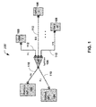
- FIG. 1 is a block diagram of one example of a Type B protected PON access network.
- FIG. 2 is a graphical representation of a method of setting up equalization delays in ranging in a PON access network.
- FIG. 3 is a graphical representation of backup optical line terminal reusing the primary ranging information.
- FIG. 4 is a flow chart representation of a process of operating an ONT in a PON.
- FIG. 5 is a block diagram representation of a portion of an ONT operable in a PON.
- This patent document discloses techniques for performing protection switching in protected passive optical networks (PONs) that are agnostic to (or independent of) equalization delay.
- PONs protected passive optical networks
- a PON system can use optical fiber to connect the user premises to the provider communication facility.
- the PON optical delivery/data network can include a point-to-multipoint (P2MP) optical fiber infrastructure where passive branching points can be represented by optical splitters are other similar passive optical devices. These passive ODN equipments can be deployed in street cabinets, closets, underground utility holes, cable chambers, and other installations and require no electrical power and little maintenance.
- the PON ODN can be attached to the optical line terminal (OLT), also called optical network terminal (ONT) with a single strain of optical fiber.
- the PON ODN can employ wavelength-division duplex or multiplexing methods to differentiate between downstream (from OLT to users) and upstream (from users to OLT) transmissions, i.e., downstream and upstream optical signals can be carried on different standardized wavelengths.
- Support of multiple users (ONUs) on the same ODN can be achieved using the methods of time-division multiplexing (TDM) in the downstream direction and time-division multiple access (TDMA) in the upstream direction.
- TDM time-division multiplexing
- TDMA time-division multiple access
- Standard-based PON systems such as Ethernet PON (EPON), Broadband PON (BPON), Gigabit PON (G-PON), 10 Gigabit/sec EPON (10G-PON), and X Gigabit/sec PON (XG-PON), can be distinguished based on one or more parameters, e.g., nominal transmission rates, optical layer parameters, or the link layer protocol and formats.
- These standard-based PON systems can share the TDMA method, which can also share associated vulnerabilities in the TDMA method.
- TDMA techniques all ONUs attached to their given ODN infrastructure can perform upstream transmission on the same wavelength, which may result in ONU interference with each other, unless the ONUs follow a strict access procedure.
- the respective standard can define a multiple access protocol, including procedures and data structures, by which the OLT is able to assign the exact transmission time slots to the individual ONUs. This assignment attempts to prevent interference in upstream transmissions by different ONUs, whereas the appropriate guard time slots serve to accommodate by using the possible transmission time drift.
- the guard times also alleviate any potential interference caused due to different propagation delays through the optical medium due to differences in the lengths of fiber medium between each ONU and the OLT.
- Various standards organizations e.g., IEEE and ITU have defined certain protection architectures based on the arrangement of OLTs and ONUs.
- Some example architectures include: Type A, Type B, Type B dual homing, Type C, Type D, and so on.
- a first stage splitter has 2 ports on the network-facing side, thus allowing “dual homing”, or duplication of the OLT and the feeder fiber between the OLT and the network-facing port of the first stage splitter.
- one OLT is designated as a primary
- the other OLT is designated as a backup which is used to replace or backup the primary when the primary fails.
- the backup OLT may not transmit downstream, but may remain powered up and listen to the upstream transmissions. In case of a failure of the primary OLT or the primary feeder cable, the backup OLT takes over control of the PON tree and resumes service to the subtending ONUs.
- the ONUs could be “ranged” with respect to the working OLT. That is, the logical distance between the OLT and each of the ONUs could be measured, and the corresponding equalization delay communicated to each individual ONU. Once the ONUs know and follow their assigned equalization delays, they appear at the same logical distance from the OLT, thus making their upstream transmissions aligned at a common upstream frame reference.
- a backup OLT may reside in the same facility (e.g., a network operator's central office) as the primary OLT and therefore may have a same length of optical fiber between itself and the ONUs served.
- the propagation delays to/from the backup OLT may be (almost) identical to that from the primary OLT. In such cases, when a backup OLT takes over after the failure of the primary OLT, performance of the optical network may not suffer.
- a backup OLT may be located at a location different from the primary OLT or the length of fiber between the backup OLT and the served ONUs may be different from that of the primary OLT. Therefore, for seamless switchover, in some embodiments, for correct ranging of the ONUs with respect to the backup OLT in case of protection switching, the backup OLT has either to pre-range the ONUs before the switchover event, or to re-range the ONUs after the switchover event.
- a backup OLT may immediately resume regular operations relying on the ONU's knowledge of the equalization delays obtained via the primary path, while optionally executing a limited set of maintenance operations.
- the set of Equalization Delays (EqDs) computed over the primary path (to/from the primary OLT) may remain valid for the backup path (to/from the backup OLT).
- the dual-homing ODN 100 includes two point-to-multipoint OLTs 102 , 104 that have distinct trunk segments (feeder fibers 110 ) and share a distribution segment composed of a 2 ⁇ N splitter 106 and a collection of drop fibers 112 respectively connected to ONUs 108 .
- any multistage splitting may be represented by an equivalent drop fiber between the first-stage splitter and the ONU 108 .
- OLTs 102 , 104 are two OLTs (e.g., identically modules in some implementations) and each can be switched between a primary mode of operation and a backup mode of operation.
- one of OLTs 102 , 104 can be the primary OLT while the other OLT (e.g., OLT 104 ) can be the backup OLT.
- the ODN 100 includes OLT ( 102 or 104 ), with the OLT including an operation state module that maintains an operational state in the ODN 100 , an upstream estimation module that estimates an upstream channel, a delay adjustment module that adjusts equalization delay and physical layer frame offset values, and a backup module that switches from a backup mode to a primary mode of operation when the OLT initially operates as the backup OLT while another OLT initially operates as the primary OLT.
- the effective fiber length of the primary feeder fiber be F 0
- the effective fiber length of the backup feeder fiber F 1
- the effective fiber lengths of the drop fibers D 1 , . . . , DN.
- the effective fiber length of the splitter and other passive elements of the ODN is negligible.
- P 1 , . . . PN denote the ONU response times.
- the ODN is constructed so that the following condition holds: R min ⁇ MAX ⁇ F 0 ,F 1 ⁇ +MAX i ( Di ) ⁇ R max Equation (1).
- a chart 200 is depicted, in which distance of various elements of PON are represented on the vertical axis 204 and time is represented on the horizontal axis 202 , in the process of ranging, the OLT selects the upstream PHY frame offset with respect to the downstream PHY frame (this parameter is also known as zero-distance equalization delay), and measures the round-trip time for each ONU.
- the round-trip time is composed of the round-trip propagation delay and the ONU response time.
- the OLT computes and communicates to the ONU the individual equalization delay, that is, the extra requisite delay that precisely aligns the ONU view on the start of an upstream PHY frame with the offset selected by the OLT.
- the adjusted round trip time (composed of the round-trip propagation delay, the ONU response time, AND equalizations delay) for all ONUs is equal to the selected PHY frame offset.
- Tmax The selected upstream PHY frame offset, Tmax, should at least be equal to the largest round-trip time among the ONUs in the system, and in practice does not have to exceed the upper bound based on the network design parameters: T max ⁇ R max( n 1+ n 2)/ c+P max Equation (2)
- n 1 and n 2 are refractive indices for the upstream and downstream wavelengths
- c is the speed of light
- Pmax is the maximum ONU response time established by the standard.
- T max ( F 0+ D *)( n 1+ n 2)/ c Equation (3)
- the OLT may schedule upstream transmissions within each PHY frame by relating them to the common upstream PHY frame reference in the bandwidth map.
- a chart 300 is shown illustrating how a backup OLT can reuse ranging information of a primary OLT.
- primary OLT having the feeder fiber length F 0 and backup OLT with feeder fiber length F 1 .
- the adjusted round-trip times for all ONUs remain identically equal to each other, albeit the upstream PHY frame offset changes.
- T max′ Eq Di +[( F 1 +Di )( n 1+ n 2)/ c+Pi];] Equation (5)
- T max′ ⁇ T max ( F 1 ⁇ F 0)( n 1+ n 2)/ c] Equation (6)
- the backup OLT may reuse the Equalization delays computed and communicated to the ONUs by the primary OLT, without performing ranging on its own and without even knowing the values of the primary EqDs.
- the backup OLT may construct bandwidth maps in a usual fashion by relating the upstream transmissions to the common upstream PHY frame reference. The backup OLT, however, should be ready to detect the upstream burst at an arbitrary time as the upstream PHY frame offset is not initially known after the switchover.
- the difference between the upstream PHY frame offset used by the backup OLT and that used by the primary OLT may only be a function of refractive index of their respective fiber drops and the difference in lengths of the fiber drops to the splitter.
- Tmax′ value used by the backup OLT may be adjusted from the Tmax value used by the primary OLT, without the backup OLT needing additional information about fiber drop lengths to the ONUs.
- the backup OLT can mitigate the drift by providing additional guard time between the upstream bursts in the bandwidth maps. Furthermore, depending on the mechanisms offered by the TC layer of a particular PON system, the backup OLT may reacquire the ranging information without service interruptions associated with opening of the quiet windows.
- the backup OLT prior to switchover, obtains the ODN design parameters and the value of the primary upstream PHY offset, Tmax, via an off-line management channel.
- the backup OLT proceeds as follows:
- the backup OLT ensures that the subtending ONUs are in the Operation state O5.
- O5 operational state an ONU is operating normally and following the transmission schedule (grants) communicated to the ONU from the OLT.
- this is achieved by virtue of well-formed downstream transmission.
- G-PON an individual directed POPUP message may be used, unless a broadcast modified POPUP message can be used to bring the ONUs in the POPUP state directly into the O5 state.
- the backup OLT schedules the upstream transmissions by forming a bandwidth map with extended guard times between the individual bursts relating them to yet unknown upstream PHY frame reference.
- the backup OLT detects the individual upstream transmissions and observes the adjusted round-trip times of the subtending ONUs.
- the adjusted round trip times may typically form a distribution with bounded support.
- the backup OLT selects the largest observed round-trip time as an interim upstream PHY frame offset.
- the backup OLT issues individual relative equalization delay adjustments to align the ONUs at the selected interim upstream PHY frame offset. This is done with an available Ranging_Time message in XG-PON and requires a modification of a Ranging-Time message in G-PON. Alternatively, this can be done with providing a modified physical layer operations, administration and maintenance (PLOAM) messaging channel functionality to learn the effective equalization delay and using the available Ranging_Time message with absolute semantics.
- PLOAM physical layer operations, administration and maintenance
- the backup OLT may adjust the upstream PHY frame offset at the desired value by issuing a broadcast relative equalization delay adjustment. This is with an available Ranging_Time message in XG-PON and requires a modification of a Ranging-Time message in G-PON.
- the backup OLT restores the normal guard times in the bandwidth maps.
- the backup OLT which has become the serving OLT, conducts service as usual, including discovery and admission of the newly activated ONUs for which it opens a quiet window and performs ranging with equalization delay calculation.
- FIG. 4 depicts a flow chart 400 of an example process of operating an ONT in a PON to provide the primary and backup operations.
- an operational state of is maintained in the PON.
- the backup ONT may maintain various operational parameters of the PON.
- an upstream channel is estimated. As previously discussed, the estimation of upstream channel may include measuring round trip delay times of all ONUs subtended by the backup OLT.
- equalization delay and physical layer frame offset values are adjusted.
- an ONT is switched from a backup mode to a primary mode of operation upon detecting a failure condition (e.g., failover due to a primary ONT stoppage).
- a failure condition e.g., failover due to a primary ONT stoppage.
- FIG. 5 is a block diagram representation of an ONT 500 that provides both the backup and primary modes of operation and the switching between the two modes.
- the module 502 is for maintaining an operational state in a passive optical network.
- the module 504 is for estimating an upstream channel.
- the module 506 is for adjusting equalization delay and physical layer frame offset values.
- the module 508 is for switching from a backup mode to a primary mode of operation.
- the backup OLT can perform equalization delay agnostic protection switching. It will also be appreciated that the backup OLT may be able to adjust upstream PHY frame offset parameter by initially using network side parameters known a priori, e.g., Equation (6), and then by performing measurements while serving as the primary OLT after the switchover.
- modules and the functional operations described in this document can be implemented in digital electronic circuitry, or in computer software, firmware, or hardware, including the structures disclosed in this document and their structural equivalents, or in combinations of one or more of them.
- the disclosed and other embodiments can be implemented as one or more computer program products, i.e., one or more modules of computer program instructions encoded on a computer readable medium for execution by, or to control the operation of, data processing apparatus.
- the computer readable medium can be a machine-readable storage device, a machine-readable storage substrate, a memory device, a composition of matter effecting a machine-readable propagated signal, or a combination of one or more them.
- data processing apparatus encompasses all apparatus, devices, and machines for processing data, including by way of example a programmable processor, a computer, or multiple processors or computers.
- the apparatus can include, in addition to hardware, code that creates an execution environment for the computer program in question, e.g., code that constitutes processor firmware, a protocol stack, a database management system, an operating system, or a combination of one or more of them.
- a propagated signal is an artificially generated signal, e.g., a machine-generated electrical, optical, or electromagnetic signal, that is generated to encode information for transmission to suitable receiver apparatus.
- a computer program (also known as a program, software, software application, script, or code) can be written in any form of programming language, including compiled or interpreted languages, and it can be deployed in any form, including as a stand alone program or as a module, component, subroutine, or other unit suitable for use in a computing environment.
- a computer program does not necessarily correspond to a file in a file system.
- a program can be stored in a portion of a file that holds other programs or data (e.g., one or more scripts stored in a markup language document), in a single file dedicated to the program in question, or in multiple coordinated files (e.g., files that store one or more modules, sub programs, or portions of code).
- a computer program can be deployed to be executed on one computer or on multiple computers that are located at one site or distributed across multiple sites and interconnected by a communication network.
- the processes and logic flows described in this document can be performed by one or more programmable processors executing one or more computer programs to perform functions by operating on input data and generating output.
- the processes and logic flows can also be performed by, and apparatus can also be implemented as, special purpose logic circuitry, e.g., an FPGA (field programmable gate array) or an ASIC (application specific integrated circuit).
- processors suitable for the execution of a computer program include, by way of example, both general and special purpose microprocessors, and any one or more processors of any kind of digital computer.
- a processor will receive instructions and data from a read only memory or a random access memory or both.
- the essential elements of a computer are a processor for performing instructions and one or more memory devices for storing instructions and data.
- a computer will also include, or be operatively coupled to receive data from or transfer data to, or both, one or more mass storage devices for storing data, e.g., magnetic, magneto optical disks, or optical disks.
- mass storage devices for storing data, e.g., magnetic, magneto optical disks, or optical disks.
- a computer need not have such devices.
- Computer readable media suitable for storing computer program instructions and data include all forms of non volatile memory, media and memory devices, including by way of example semiconductor memory devices, e.g., EPROM, EEPROM, and flash memory devices; magnetic disks, e.g., internal hard disks or removable disks; magneto optical disks; and CD ROM and DVD-ROM disks.
- semiconductor memory devices e.g., EPROM, EEPROM, and flash memory devices
- magnetic disks e.g., internal hard disks or removable disks
- magneto optical disks e.g., CD ROM and DVD-ROM disks.
- the processor and the memory can be supplemented by, or incorporated in, special purpose logic circuitry.
Abstract
Description
Rmin≦MAX{F0,F1}+MAXi(Di)≦Rmax Equation (1).
Tmax≦Rmax(n1+n2)/c+Pmax Equation (2)
Tmax=(F0+D*)(n1+n2)/c Equation (3)
EqDi=Tmax−[(F0+Di)(n1+n2)/c+Pi] Equation (4)
Tmax′=EqDi+[(F1+Di)(n1+n2)/c+Pi];] Equation (5)
Tmax′−Tmax=(F1−F0)(n1+n2)/c] Equation (6)
Claims (19)
Priority Applications (1)
| Application Number | Priority Date | Filing Date | Title |
|---|---|---|---|
| US13/682,705 US9025949B2 (en) | 2011-12-09 | 2012-11-20 | Equalization delay agnostic protection switching in protected passive optical networks |
Applications Claiming Priority (2)
| Application Number | Priority Date | Filing Date | Title |
|---|---|---|---|
| US201161569209P | 2011-12-09 | 2011-12-09 | |
| US13/682,705 US9025949B2 (en) | 2011-12-09 | 2012-11-20 | Equalization delay agnostic protection switching in protected passive optical networks |
Publications (2)
| Publication Number | Publication Date |
|---|---|
| US20130148956A1 US20130148956A1 (en) | 2013-06-13 |
| US9025949B2 true US9025949B2 (en) | 2015-05-05 |
Family
ID=47560477
Family Applications (1)
| Application Number | Title | Priority Date | Filing Date |
|---|---|---|---|
| US13/682,705 Active 2033-05-01 US9025949B2 (en) | 2011-12-09 | 2012-11-20 | Equalization delay agnostic protection switching in protected passive optical networks |
Country Status (5)
| Country | Link |
|---|---|
| US (1) | US9025949B2 (en) |
| CN (1) | CN103166697B (en) |
| FR (1) | FR2984045B1 (en) |
| GB (2) | GB2518996B (en) |
| HK (1) | HK1186587A1 (en) |
Cited By (3)
| Publication number | Priority date | Publication date | Assignee | Title |
|---|---|---|---|---|
| US20160073180A1 (en) * | 2014-09-04 | 2016-03-10 | Verizon Patent And Licensing Inc. | Maintaining channel-invariant optical network unit (onu) equalization delay in a passive optical network |
| US20170005722A1 (en) * | 2014-01-26 | 2017-01-05 | Zte Corporation | Method and Device for Detecting Rogue Behavior |
| US10547407B2 (en) * | 2017-10-19 | 2020-01-28 | Adtran, Inc. | Enhanced passive optical network |
Families Citing this family (15)
| Publication number | Priority date | Publication date | Assignee | Title |
|---|---|---|---|---|
| WO2013082804A1 (en) * | 2011-12-09 | 2013-06-13 | 华为技术有限公司 | Data communication method for optical network system, optical line terminal and optical network system |
| WO2013096283A1 (en) * | 2011-12-22 | 2013-06-27 | Tyco Electronices Corporation | Fiber optic wall plate with redundancy system |
| WO2013147655A1 (en) * | 2012-03-28 | 2013-10-03 | Telefonaktiebolaget Lm Ericsson (Publ) | An arrangement at a remote node, a remote node, a central office and respective methods therein for supervision of a wavelength division multiplexed passive optical network |
| US8953936B2 (en) * | 2012-10-01 | 2015-02-10 | Telefonaktiebolaget L M Ericsson (Publ) | Method for protection of multi-wavelength passive optical network |
| WO2014087994A1 (en) * | 2012-12-05 | 2014-06-12 | 日本電信電話株式会社 | Discovery method, optical communication method, and optical communication system |
| TWI487304B (en) * | 2012-12-07 | 2015-06-01 | Ind Tech Res Inst | Optical network failure recovery method |
| EP2997684B1 (en) * | 2013-05-15 | 2018-10-31 | ZTE Corporation | Using noisy window for uncalibrated optical network unit activation |
| JP6053232B2 (en) * | 2013-10-25 | 2016-12-27 | 日本電信電話株式会社 | Optical communication system and optical communication error recovery method |
| KR102132491B1 (en) * | 2014-02-24 | 2020-07-09 | 한국전자통신연구원 | Fast protection switching method for Passive Optical Network |
| US20160234582A1 (en) * | 2015-02-10 | 2016-08-11 | Daniel Ronald | Method and system for redundancy in a passive optical network |
| US10608735B2 (en) * | 2016-05-04 | 2020-03-31 | Adtran, Inc. | Systems and methods for performing optical line terminal (OLT) failover switches in optical networks |
| US10764027B2 (en) * | 2016-07-07 | 2020-09-01 | Cisco Technology, Inc. | Deterministic calibrated synchronized network interlink access |
| CN111343520A (en) * | 2020-02-27 | 2020-06-26 | 通鼎互联信息股份有限公司 | PON uplink data transmission method, system and device and PON system |
| CN111555832B (en) * | 2020-04-22 | 2022-02-18 | 中国电子科技集团公司第五十四研究所 | 1+1 hot backup dual-channel synchronization and maintenance method based on continuous frame positioning |
| US11764939B1 (en) * | 2022-07-14 | 2023-09-19 | Mellanox Technologies, Ltd. | Controlling latency of cable interconnections |
Citations (11)
| Publication number | Priority date | Publication date | Assignee | Title |
|---|---|---|---|---|
| US20020171895A1 (en) | 2001-04-25 | 2002-11-21 | Glory Telecommunications Co., Ltd. | Automatic ranging in a passive optical network |
| WO2009053708A1 (en) | 2007-10-24 | 2009-04-30 | British Telecommunications Public Limited Company | Optical communication |
| CN101547044A (en) | 2008-03-27 | 2009-09-30 | 华为技术有限公司 | Method, system and repeater for reducing time delay in switching main optical line terminal and spare optical line terminal |
| WO2009124484A1 (en) | 2008-04-09 | 2009-10-15 | 华为技术有限公司 | A method, system and device for transmitting data in optical network |
| WO2010031326A1 (en) | 2008-09-19 | 2010-03-25 | 华为技术有限公司 | Method for switching data link in the optical network system, optical line terminal and system |
| US20100166419A1 (en) | 2008-12-30 | 2010-07-01 | Broadlight, Ltd. | Techniques for protecting passive optical networks |
| CN101873166A (en) * | 2009-04-21 | 2010-10-27 | 中兴通讯股份有限公司 | Method for distance measurement in gigabit passive optical network system |
| EP2249499A1 (en) | 2009-05-04 | 2010-11-10 | Mitsubishi Electric R&D Centre Europe B.V. | Method for protecting a type b passive optical network (pon) and preparing an access control take over by a protection optical line termination (olt) with fast ranging |
| CN101909222A (en) | 2009-06-03 | 2010-12-08 | 华为技术有限公司 | Optical line terminal equipment, protection method and passive optical network system |
| WO2011022883A1 (en) | 2009-08-26 | 2011-03-03 | 华为技术有限公司 | Method, apparatus and system for optical network switching protection |
| WO2011062528A1 (en) | 2009-11-18 | 2011-05-26 | Telefonaktiebolaget L M Ericsson | Overhead adjustment scheme for passive optical networks |
Family Cites Families (2)
| Publication number | Priority date | Publication date | Assignee | Title |
|---|---|---|---|---|
| EP1213862A1 (en) * | 2000-12-11 | 2002-06-12 | Marconi Communications GmbH | Optical data network with protection switching |
| US6771908B2 (en) * | 2001-02-12 | 2004-08-03 | Lucent Technologies Inc. | Fast protection switching by snooping on downstream signals in an optical network |
-
2012
- 2012-11-20 US US13/682,705 patent/US9025949B2/en active Active
- 2012-11-22 FR FR1261139A patent/FR2984045B1/en active Active
- 2012-11-22 CN CN201210478388.7A patent/CN103166697B/en active Active
- 2012-11-22 GB GB1421204.7A patent/GB2518996B/en active Active
- 2012-11-22 GB GB1221002.7A patent/GB2498049B/en active Active
-
2013
- 2013-12-13 HK HK13113868.7A patent/HK1186587A1/en unknown
Patent Citations (15)
| Publication number | Priority date | Publication date | Assignee | Title |
|---|---|---|---|---|
| US20020171895A1 (en) | 2001-04-25 | 2002-11-21 | Glory Telecommunications Co., Ltd. | Automatic ranging in a passive optical network |
| WO2009053708A1 (en) | 2007-10-24 | 2009-04-30 | British Telecommunications Public Limited Company | Optical communication |
| CN101836379A (en) | 2007-10-24 | 2010-09-15 | 英国电讯有限公司 | Optical communication |
| EP2214344A1 (en) * | 2008-03-27 | 2010-08-04 | Huawei Technologies Co., Ltd. | Method system and repeater for reducing switch delay of main and spare optical line termination |
| CN101547044A (en) | 2008-03-27 | 2009-09-30 | 华为技术有限公司 | Method, system and repeater for reducing time delay in switching main optical line terminal and spare optical line terminal |
| WO2009124484A1 (en) | 2008-04-09 | 2009-10-15 | 华为技术有限公司 | A method, system and device for transmitting data in optical network |
| WO2010031326A1 (en) | 2008-09-19 | 2010-03-25 | 华为技术有限公司 | Method for switching data link in the optical network system, optical line terminal and system |
| US20100166419A1 (en) | 2008-12-30 | 2010-07-01 | Broadlight, Ltd. | Techniques for protecting passive optical networks |
| CN101873166A (en) * | 2009-04-21 | 2010-10-27 | 中兴通讯股份有限公司 | Method for distance measurement in gigabit passive optical network system |
| EP2249499A1 (en) | 2009-05-04 | 2010-11-10 | Mitsubishi Electric R&D Centre Europe B.V. | Method for protecting a type b passive optical network (pon) and preparing an access control take over by a protection optical line termination (olt) with fast ranging |
| CN101909222A (en) | 2009-06-03 | 2010-12-08 | 华为技术有限公司 | Optical line terminal equipment, protection method and passive optical network system |
| WO2011022883A1 (en) | 2009-08-26 | 2011-03-03 | 华为技术有限公司 | Method, apparatus and system for optical network switching protection |
| EP2426856A1 (en) | 2009-08-26 | 2012-03-07 | Huawei Technologies Co., Ltd. | Method, apparatus and system for optical network switching protection |
| US20120082449A1 (en) | 2009-08-26 | 2012-04-05 | Huawei Technologies Co., Ltd. | Method, device and system for optical network switching protection |
| WO2011062528A1 (en) | 2009-11-18 | 2011-05-26 | Telefonaktiebolaget L M Ericsson | Overhead adjustment scheme for passive optical networks |
Non-Patent Citations (4)
| Title |
|---|
| Office Action dated Jan. 23, 2015 for Chinese Patent Application No. 201210478388.7, filed Nov. 22, 2012 (6 pages). |
| Search and Examination Report dated Apr. 23, 2013 for UK Patent Application No. 1221002.7, filed Nov. 22, 2012 (7 pages). |
| Search and Examination Report dated Aug. 1, 2014 for UK Patent Application No. 1221002.7, filed Nov. 22, 2012 (5 pages). |
| Search and Examination Report dated Feb. 2, 2015 for UK Patent Application No. 1421204.7, filed Nov. 28, 2014 (4 pages). |
Cited By (5)
| Publication number | Priority date | Publication date | Assignee | Title |
|---|---|---|---|---|
| US20170005722A1 (en) * | 2014-01-26 | 2017-01-05 | Zte Corporation | Method and Device for Detecting Rogue Behavior |
| US9806802B2 (en) * | 2014-01-26 | 2017-10-31 | Xi'an Zhongxing New Software Co. Ltd. | Method and device for detecting rogue behavior |
| US20160073180A1 (en) * | 2014-09-04 | 2016-03-10 | Verizon Patent And Licensing Inc. | Maintaining channel-invariant optical network unit (onu) equalization delay in a passive optical network |
| US9473836B2 (en) * | 2014-09-04 | 2016-10-18 | Verizon Patent And Licensing Inc. | Maintaining channel-invariant optical network unit (ONU) equalization delay in a passive optical network |
| US10547407B2 (en) * | 2017-10-19 | 2020-01-28 | Adtran, Inc. | Enhanced passive optical network |
Also Published As
| Publication number | Publication date |
|---|---|
| GB2518996A (en) | 2015-04-08 |
| CN103166697A (en) | 2013-06-19 |
| GB201221002D0 (en) | 2013-01-09 |
| GB201421204D0 (en) | 2015-01-14 |
| HK1186587A1 (en) | 2014-03-14 |
| GB2498049A (en) | 2013-07-03 |
| FR2984045B1 (en) | 2018-04-13 |
| US20130148956A1 (en) | 2013-06-13 |
| CN103166697B (en) | 2016-03-02 |
| FR2984045A1 (en) | 2013-06-14 |
| GB2498049B (en) | 2015-03-11 |
| GB2518996B (en) | 2015-08-12 |
Similar Documents
| Publication | Publication Date | Title |
|---|---|---|
| US9025949B2 (en) | Equalization delay agnostic protection switching in protected passive optical networks | |
| US10148358B2 (en) | Broadband optical network apparatus and method | |
| US8655168B2 (en) | Passive optical network maintenance method, an optical network unit, and an optical line terminal | |
| US9473836B2 (en) | Maintaining channel-invariant optical network unit (ONU) equalization delay in a passive optical network | |
| US8818201B2 (en) | Optical communication | |
| AU2012385350B2 (en) | Wavelength negotiation method and apparatus of multi-wavelength passive optical network, and multi-wavelength passive optical network system | |
| CN102075238B (en) | Passive optical network and protection switching method thereof | |
| US20130034356A1 (en) | Rogue Optical Network Unit Mitigation in Multiple-Wavelength Passive Optical Networks | |
| EP3229486B1 (en) | Method and apparatus for detecting optical network unit, and passive optical network system | |
| US20070230958A1 (en) | Method and System for Maintenance of a Passive Optical Network | |
| US10020889B2 (en) | Channel ranging adjustment in multiple-wavelength passive optical networks (PONs) | |
| CN103378918B (en) | Channel method of adjustment and device | |
| US9167323B2 (en) | Method and system for quickly updating ranging results of optical network unit by optical line terminal | |
| US20090028553A1 (en) | Method and apparatus of detecting abnormal behavior in a passive optical network (PON) | |
| US9871614B2 (en) | WDM/TDM-PON system and transmission start time correction method thereof | |
| CN102149027A (en) | Passage switching method and system and downlink data transmitting method | |
| JP2011217298A (en) | Pon system, station-side device and terminal-side device thereof, and rtt correction method | |
| US10084592B2 (en) | Skew calculation in channel-bonded passive optical networks (PONs) | |
| CN103248418B (en) | A kind of primary channel changing method based on EPON and system | |
| CN103139669A (en) | Method and system for sending data | |
| US8879914B2 (en) | Low-energy optical network architecture | |
| WO2009017469A1 (en) | Method and apparatus of detecting abnormal behavior in a passive optical network (pon) | |
| Doo et al. | Design of a retimed long-reach GPON Extender using FPGA |
Legal Events
| Date | Code | Title | Description |
|---|---|---|---|
| AS | Assignment |
Owner name: ZTE CORPORATION, CHINA Free format text: ASSIGNMENT OF ASSIGNORS INTEREST;ASSIGNORS:GENG, DAN;ZHANG, WEILIANG;REEL/FRAME:035205/0520 Effective date: 20150319 Owner name: ZTE (USA) INC., TEXAS Free format text: ASSIGNMENT OF ASSIGNORS INTEREST;ASSIGNOR:KHOTIMSKY, DENIS ANDREYEVICH;REEL/FRAME:035205/0389 Effective date: 20130214 |
|
| STCF | Information on status: patent grant |
Free format text: PATENTED CASE |
|
| MAFP | Maintenance fee payment |
Free format text: PAYMENT OF MAINTENANCE FEE, 4TH YEAR, LARGE ENTITY (ORIGINAL EVENT CODE: M1551); ENTITY STATUS OF PATENT OWNER: LARGE ENTITY Year of fee payment: 4 |
|
| MAFP | Maintenance fee payment |
Free format text: PAYMENT OF MAINTENANCE FEE, 8TH YEAR, LARGE ENTITY (ORIGINAL EVENT CODE: M1552); ENTITY STATUS OF PATENT OWNER: LARGE ENTITY Year of fee payment: 8 |