US9011177B2 - High speed bypass cable assembly - Google Patents
High speed bypass cable assembly Download PDFInfo
- Publication number
- US9011177B2 US9011177B2 US13/987,296 US201113987296A US9011177B2 US 9011177 B2 US9011177 B2 US 9011177B2 US 201113987296 A US201113987296 A US 201113987296A US 9011177 B2 US9011177 B2 US 9011177B2
- Authority
- US
- United States
- Prior art keywords
- cable
- connector
- signal conductors
- shield
- signal
- Prior art date
- Legal status (The legal status is an assumption and is not a legal conclusion. Google has not performed a legal analysis and makes no representation as to the accuracy of the status listed.)
- Ceased, expires
Links
Images


Classifications
-
- H—ELECTRICITY
- H01—ELECTRIC ELEMENTS
- H01R—ELECTRICALLY-CONDUCTIVE CONNECTIONS; STRUCTURAL ASSOCIATIONS OF A PLURALITY OF MUTUALLY-INSULATED ELECTRICAL CONNECTING ELEMENTS; COUPLING DEVICES; CURRENT COLLECTORS
- H01R13/00—Details of coupling devices of the kinds covered by groups H01R12/70 or H01R24/00 - H01R33/00
- H01R13/646—Details of coupling devices of the kinds covered by groups H01R12/70 or H01R24/00 - H01R33/00 specially adapted for high-frequency, e.g. structures providing an impedance match or phase match
- H01R13/6461—Means for preventing cross-talk
-
- H—ELECTRICITY
- H01—ELECTRIC ELEMENTS
- H01B—CABLES; CONDUCTORS; INSULATORS; SELECTION OF MATERIALS FOR THEIR CONDUCTIVE, INSULATING OR DIELECTRIC PROPERTIES
- H01B11/00—Communication cables or conductors
-
- H—ELECTRICITY
- H01—ELECTRIC ELEMENTS
- H01R—ELECTRICALLY-CONDUCTIVE CONNECTIONS; STRUCTURAL ASSOCIATIONS OF A PLURALITY OF MUTUALLY-INSULATED ELECTRICAL CONNECTING ELEMENTS; COUPLING DEVICES; CURRENT COLLECTORS
- H01R13/00—Details of coupling devices of the kinds covered by groups H01R12/70 or H01R24/00 - H01R33/00
- H01R13/646—Details of coupling devices of the kinds covered by groups H01R12/70 or H01R24/00 - H01R33/00 specially adapted for high-frequency, e.g. structures providing an impedance match or phase match
- H01R13/6461—Means for preventing cross-talk
- H01R13/6471—Means for preventing cross-talk by special arrangement of ground and signal conductors, e.g. GSGS [Ground-Signal-Ground-Signal]
-
- H—ELECTRICITY
- H01—ELECTRIC ELEMENTS
- H01R—ELECTRICALLY-CONDUCTIVE CONNECTIONS; STRUCTURAL ASSOCIATIONS OF A PLURALITY OF MUTUALLY-INSULATED ELECTRICAL CONNECTING ELEMENTS; COUPLING DEVICES; CURRENT COLLECTORS
- H01R13/00—Details of coupling devices of the kinds covered by groups H01R12/70 or H01R24/00 - H01R33/00
- H01R13/648—Protective earth or shield arrangements on coupling devices, e.g. anti-static shielding
- H01R13/658—High frequency shielding arrangements, e.g. against EMI [Electro-Magnetic Interference] or EMP [Electro-Magnetic Pulse]
- H01R13/6591—Specific features or arrangements of connection of shield to conductive members
- H01R13/6592—Specific features or arrangements of connection of shield to conductive members the conductive member being a shielded cable
- H01R13/6593—Specific features or arrangements of connection of shield to conductive members the conductive member being a shielded cable the shield being composed of different pieces
-
- H—ELECTRICITY
- H05—ELECTRIC TECHNIQUES NOT OTHERWISE PROVIDED FOR
- H05K—PRINTED CIRCUITS; CASINGS OR CONSTRUCTIONAL DETAILS OF ELECTRIC APPARATUS; MANUFACTURE OF ASSEMBLAGES OF ELECTRICAL COMPONENTS
- H05K1/00—Printed circuits
- H05K1/02—Details
- H05K1/0213—Electrical arrangements not otherwise provided for
- H05K1/0237—High frequency adaptations
- H05K1/0243—Printed circuits associated with mounted high frequency components
-
- H—ELECTRICITY
- H05—ELECTRIC TECHNIQUES NOT OTHERWISE PROVIDED FOR
- H05K—PRINTED CIRCUITS; CASINGS OR CONSTRUCTIONAL DETAILS OF ELECTRIC APPARATUS; MANUFACTURE OF ASSEMBLAGES OF ELECTRICAL COMPONENTS
- H05K3/00—Apparatus or processes for manufacturing printed circuits
- H05K3/22—Secondary treatment of printed circuits
- H05K3/222—Completing of printed circuits by adding non-printed jumper connections
-
- H—ELECTRICITY
- H05—ELECTRIC TECHNIQUES NOT OTHERWISE PROVIDED FOR
- H05K—PRINTED CIRCUITS; CASINGS OR CONSTRUCTIONAL DETAILS OF ELECTRIC APPARATUS; MANUFACTURE OF ASSEMBLAGES OF ELECTRICAL COMPONENTS
- H05K2201/00—Indexing scheme relating to printed circuits covered by H05K1/00
- H05K2201/10—Details of components or other objects attached to or integrated in a printed circuit board
- H05K2201/10007—Types of components
- H05K2201/10189—Non-printed connector
-
- H—ELECTRICITY
- H05—ELECTRIC TECHNIQUES NOT OTHERWISE PROVIDED FOR
- H05K—PRINTED CIRCUITS; CASINGS OR CONSTRUCTIONAL DETAILS OF ELECTRIC APPARATUS; MANUFACTURE OF ASSEMBLAGES OF ELECTRICAL COMPONENTS
- H05K2201/00—Indexing scheme relating to printed circuits covered by H05K1/00
- H05K2201/10—Details of components or other objects attached to or integrated in a printed circuit board
- H05K2201/10227—Other objects, e.g. metallic pieces
- H05K2201/10356—Cables
-
- H—ELECTRICITY
- H05—ELECTRIC TECHNIQUES NOT OTHERWISE PROVIDED FOR
- H05K—PRINTED CIRCUITS; CASINGS OR CONSTRUCTIONAL DETAILS OF ELECTRIC APPARATUS; MANUFACTURE OF ASSEMBLAGES OF ELECTRICAL COMPONENTS
- H05K2201/00—Indexing scheme relating to printed circuits covered by H05K1/00
- H05K2201/10—Details of components or other objects attached to or integrated in a printed circuit board
- H05K2201/10431—Details of mounted components
- H05K2201/10439—Position of a single component
- H05K2201/10446—Mounted on an edge
-
- H—ELECTRICITY
- H05—ELECTRIC TECHNIQUES NOT OTHERWISE PROVIDED FOR
- H05K—PRINTED CIRCUITS; CASINGS OR CONSTRUCTIONAL DETAILS OF ELECTRIC APPARATUS; MANUFACTURE OF ASSEMBLAGES OF ELECTRICAL COMPONENTS
- H05K2201/00—Indexing scheme relating to printed circuits covered by H05K1/00
- H05K2201/10—Details of components or other objects attached to or integrated in a printed circuit board
- H05K2201/10613—Details of electrical connections of non-printed components, e.g. special leads
- H05K2201/10621—Components characterised by their electrical contacts
- H05K2201/10674—Flip chip
Definitions
- the Present Disclosure relates generally to cable interconnection systems, and more particularly, to bypass cable interconnection systems for transmitting high speed signals at low losses.
- Conventional cable interconnection systems are found in electronic devices such as routers and servers and the like, and are used to form a signal transmission line that extends between a primary chip member mounted on a printed circuit board of the device, such as an ASIC, and a connector mounted to the circuit board.
- the transmission line typically takes the form of a plurality of conductive traces that are etched, or otherwise formed on or as part of the printed circuit board. These traces extend between the chip member and a connector that provides a connection between one or more external plug connectors and the chip member.
- Circuit boards are usually formed from a material known as FR-4, which is inexpensive. However, FR-4 is known to promote losses in high speed signal transmission lines, and these losses make it undesirable to utilize FR-4 material for high speed applications (10 GHz and above).
- Custom materials for circuit boards are available that reduce such losses but the price of these materials severely increase the cost of the circuit board and, consequently, the electronic devices in which they are used.
- the overall length of the transmission line typically may well exceed 10 inches in length. These long lengths require that the signals traveling through the transmission line be amplified and repeated, thereby increasing the cost of the circuit board, and complicating the design inasmuch as additional board space is needed to accommodate these amplifiers and repeaters.
- the routing of the traces of such a transmission line in the FR-4 may require multiple turns and the transitions which occur at terminations affect the integrity of the signals transmitted thereby. It becomes difficult to route transmission line traces in a manner so as to achieve consistent impedance and a low signal loss therethrough.
- the Present Disclosure is therefore directed to a high speed, bypass cable assembly that defines a transmission line for transmitting high speed signals, 10 GHz and greater that removes the transmission line from on the circuit board and which has low loss characteristics.
- an improved high speed bypass cable assembly that defines a signal transmission line useful for high speed applications at 10 GHz or above and with low loss characteristics.
- an electrical connector assembly comprises a printed circuit board, a chip member, a termination member, a first connector member, a bypass cable member and a second connector member.
- the chip member and the termination member are mounted on the printed circuit board, with the termination member mounted toward the end of the printed circuit board.
- the first connector member is in electrical communication with the chip member at a first end
- the bypass cable member electrically connects the first connector member, where it is coupled at a second end thereof, and the termination member, at a first end.
- the second connector member disposed at a second end of the termination member, is in electrical communication with the termination member.
- the electrical connector is capable of the transmission of high speed signals.
- the bypass cable provides a transmission line therebetween that has a consistent geometry and structure that resists signal loss and maintains the system impedance at a consistent level without discontinuities.
- the cable bypass assembly provides a transmission line that is separate from the circuit board, and may include one or more associated signal wire pairs, such as is found in “twin-ax” cable.
- the wires of the bypass cable are configured at their opposite ends in two fashions. At a first end of the bypass cable, the wires are configured for a direct termination to a board mounted connector, and are arranged in a manner such that the conductors of the signal wires extend in alignment with terminal termination ends, or feet, of the board mounted connector.
- the shielding of the signal wires are rolled back upon the insulative coating of the wires and exterior shield extensions are preferably provided to ensure that the signal wire conductor leads are effectively shielded through the connection.
- the terminal tails need not be attached to the circuit board, either as surface mount or through hole tails, thereby significantly reducing losses and the impedance discontinuity that occurs in the tail to board mounting transition.
- the signal wires are terminated in a fashion so that they can either be connected directly to the chip member or to the board in close proximity to the chip member.
- the signal wire conductors are terminated to associated tail portions that are aligned with the conductors, similar to the termination which occurs at the first end. These tails are maintained in a desired spacing and are further completely shielded by a surrounding conductive enclosure to provide full EMI shielding and reduction of cross talk.
- the termination of the ends of the bypass cable assembly are done in a manner such that to the extent possible, the geometry of the conductors in the bypass cable is maintained through the termination of the cable to the board connector and/or the chip.
- FIG. 1 illustrates a perspective view of one embodiment of a high speed interconnect cable assembly, developed in accordance with the Present Disclosure
- FIG. 2 illustrates a perspective view of another embodiment of a high speed interconnect cable assembly, developed in accordance with the Present Disclosure
- FIG. 3 illustrates a perspective view of another embodiment of a high speed interconnect cable assembly, developed in accordance with the Present Disclosure
- FIG. 4 illustrates a perspective and inset view of the via transfer connector of the interconnect cable assembly of FIG. 3 ;
- FIG. 5 illustrates a perspective and inset view of the first connector member of the interconnect cable assembly of FIG. 3 ;
- FIG. 6 is a perspective view of a second embodiment of a cable bypass assembly constructed in accordance with the Present Disclosure
- FIG. 7 is a top plan view of the cable bypass assembly of FIG. 6 ;
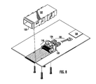
- FIG. 8 is an exploded view of the assembly of FIG. 6 , illustrating in greater detail the board connector to which the cable bypass assembly is terminated;
- FIG. 9 is a perspective view of the board mounted connector of FIG. 8 , with the first ends of the bypass assembly attached thereto;
- FIG. 10 is a partially exploded view of FIG. 9 ;
- FIG. 11 is a top plan view of FIG. 9 , with the EMI shield removed for clarity;
- FIG. 11A is a side elevational view of FIG. 11 ;
- FIG. 12 is perspective view of four pairs of signal wires terminated to the board connector terminal assembly and with one set of the shielding extensions removed for clarity;
- FIG. 12A is the same view as FIG. 12 , but taken from the rear thereof;
- FIG. 12B is a end view of two pairs of signal wires with an associated shielding extension in place, illustrating the relative alignments of the signal conductors with each other and to the shielding of the cables;
- FIG. 13 is a perspective view of one manner of terminating the ends of the cables of the cable bypass assembly which is opposite that of the termination to the board mounted connector;
- FIG. 13A is the same view as FIG. 13 , but with one of the exterior shielding components removed for clarity;
- FIG. 13B is the same view as FIG. 13A but with the lower shielding component removed and the terminal support in place on the terminals attached to the second end of the cable;
- FIG. 13C is the same view as FIG. 13B but with the terminal support removed for clarity;
- FIG. 13D is the same view as FIG. 13C , but taken from the other end thereof;
- FIG. 13E is a sectional view of FIG. 13 ;
- FIG. 14 is an embodiment of a termination structure for direct connection to a chip member
- FIG. 14A is an exploded view of FIG. 14 ;
- FIG. 14B is an enlarged detail view of FIG. 14A .
- FIG. 15 is a partially exploded view of an extent of flexible circuitry which may be used as a signal transmission line in cable bypass assemblies of the disclosure.
- FIG. 16 is a graph comparing the losses between 12-inch lengths of signal transmission lines incorporated on a circuit board made from FR-4 material and a cable bypass assembly constructed in accordance with the principles of the disclosure.
- representations of directions such as up, down, left, right, front and rear, used for explaining the structure and movement of the various elements of the Present Application are not absolute, but relative. These representations are appropriate when the elements are in the position shown in the Figures. If the description of the position of the elements changes, however, these representations are to be changed accordingly.
- FIGS. 1-5 provide various perspective views of some basic components of a high speed interconnect cable assembly, developed in accordance with the teachings and tenets of the Present Disclosure.
- high speed interconnect cable assembly 10 generally comprises chip member 12 mounted on printed circuit board member 14 , first connector member 16 interfacing between chip member 12 and bypass cable member 18 , and termination member 20 interfacing between bypass cable member 18 and second connector member 22 disposed at the edge of printed circuit board member 14 .
- chip member 12 may comprise a PHY Chip, or any other surface-mounted, physical layer device, known in the art, from which a high speed signal is generated, such as an ASIC and transmitted to a cable assembly.
- Chip member 12 is mounted to any currently-known printed circuit board, using preferably any of the various currently-known mounting means.
- an FR-4 type printed circuit board is used, in an effort to take advantage of its low cost and wide usage.
- the generated high speed signal may be any type of signal, but typically a data signal, generally having a frequency of 5 GHz and above, and most preferably and is a data signal having a frequency of 10 GHz or more.
- Bypass cable member 18 is connected to chip member 12 by means of first connector member 16 .
- First connector member 16 is capable of transmitting a signal greater than 10 GHz between chip member 12 and bypass cable member 18 .
- the interface between first connector member 16 and chip member 18 may be by any known means, including, for example, a plug-receptacle connection, a friction-based connection or the like. It is preferred that the interface be removable.
- First connector member 16 is preferably capable of receiving the high speed signal generated by the chip member and transmitting it to the bypass cable member without need for a repeater or an amplifier, and without having to use the conductive properties of printed circuit board 14 .
- bypass cable member 18 comprises a flexible circuit member, such as a cable, extending from first connector member 16 to termination member 20 .
- bypass cable member 18 is capable of receiving and carrying signals above 10 GHz.
- bypass cable member 18 includes one or more wire pairs that transmit differential signals at high speeds. Each such wire pair may have a ground, or drain, wire associated with it. Further, the pairs may be enclosed within bypass cable member 18 and within an associated cable shield.
- bypass cable member 18 is preferably capable of receiving the high speed signal generated by first connector member 18 and transmitting it to termination member 20 without need for a repeater or an amplifier, and without having to use the conductive properties of printed circuit board 14 .
- Termination member 20 is electrically connected to bypass cable member 18 , and receives the signal from bypass cable member 18 . Like all other elements in interconnection assembly 10 , termination member 20 is capable of receiving signals greater than 10 GHz. Preferably, termination member 20 is located at or near the edge of printed circuit board 14 . Termination member 20 may be mounted to the edge of printed circuit board 14 . Alternatively, termination member 20 may be “freestanding,” and not connected to any aspect of assembly 10 . Termination member 20 may receive bypass cable member 18 though any methods and means as currently described in the art.
- Second connector member 22 preferably provides one end of a male-female relationship with termination member 20 (with termination member 20 providing the second end). It is not imperative that second connector member 22 (or termination member 20 ) be specifically relegated to the male or female end, as the teachings of the Present Disclosure will nevertheless be realized.
- Second connector member 22 is preferably not disposed on any other aspect of interconnection assembly 10 of the Present Disclosure, i.e., second connector member 22 is not mounted on printed circuit board 14 . Second connector member 22 receives the signal from termination member 20 , and transmits the signal to its next or final destination.
- lamination member 24 may encompass all or part of multiple bypass cable members 18 for ease in assembly, as well as to maintain order on printed circuit board 14 and reduce the cost of assembly 10 .
- lamination member 24 may comprise a rigid, formable polymer material that can be molded over both first connector member 16 and bypass cable member 18 .
- bypass cable members 18 extend from chip members 12 , via first connector member 16 , towards first via transfer connectors 28 .
- Each via transfer connector 28 allows the signal being carried in bypass cable members 18 to pass through holes (or vias) in the printed circuit board where they connect with termination member 26 .
- FIG. 4 illustrates a perspective close up of the connection of via transfer connectors 28 to termination member (not shown in FIG. 4 ).
- each via transfer connector 28 houses the termination of bypass cable members 18 .
- Individual wires 30 extending from bypass cable members 18 are mounted within connector housing 32 .
- Connector housing 32 , along with individual wires 30 and a portion of bypass cable members 18 are overmolded with terminal housing 34 .
- Terminal housing 34 is then inserted into the via hole of the printed circuit board, where it couples to termination member.
- FIG. 5 illustrates a perspective close up of first connector member 16 .
- each first connector 16 houses the termination of bypass cable members 18 .
- Individual wires 36 extending from bypass cable members are overmolded with terminal housing 38 .
- Terminal housing 38 is then coupled to chip member 12 .
- FIGS. 6-13E illustrate another embodiment of a bypass cable assembly 100 constructed in accordance with the principles of the Present Disclosure.
- a circuit board 101 that is used in an electronic device (not shown) has mounted thereon a chip member 104 , such as an ASIC, at one location and a shielding cage 102 mounted to the circuit board at another location, remote from the one location.
- the shielding cage 102 houses a receptacle connector assembly 110 that includes a receptacle connector 112 configured to receive the mating blade (typically the leading edge of a circuit card) of an opposing, mating connector (not shown) in a elongated card-receiving slot 113 .
- the connector 112 may also include a channel 114 disposed underneath the card slot 113 to receive a polarizing member of the mating connector.
- the connector 112 is accessible through an opening 103 at one end of the shielding cage 102 .
- a portion of the shielding cage 102 extends past the edge of the circuit board 101 and out of the enclosure which houses the circuit board 101 .
- This opening 103 permits access to the connector 112 from the exterior of the device and permits the insertion of a mating connector, typically in the form of a plug connector, therein in order to connect the device to another device and permit the transfer of signals between them.
- a bypass cable assembly 105 is provided to connect together, the connector 112 and the chip member 104 , in order to form a signal transmission line extending therebetween for transmitting signals at high speeds of approximately 5 GHz and greater and preferably of approximately 10 GHz and greater.
- the cable assembly 105 includes a preselected length of cable 107 that has at a first end 107 a thereof, a first termination assembly and at a second and opposite end 107 b thereof, a second termination assembly.
- each cable 107 may be of the “twin-ax” type, in which a pair of signal conductors 144 A, 144 B are positioned in spaced-apart relationship within an insulative body 142 .
- This cable body 142 is surrounded by an outer conductive shielding layer 148 that is located underneath an exterior, insulative covering 140 and all of the cable elements may be formed as the single component illustrated.
- the structure of this particular type of twin-ax cable lends itself to uniformity throughout its length so that a consistent impedance profile is attained for the length of the cable.
- the cable assemblies 105 of this disclosure may include as few as one or two cables, or they may include greater numbers, such as the eight cables shown in FIGS. 6 , 9 & 11 .
- the cables 107 are used as the signal transmission lines.
- the cables 107 are made in a manner that controls their size, thickness and the position and spacing of the signal conductors 144 A, 144 B so as to define a constant impedance profile throughout the lengths of the cables. Accordingly, twin-ax type of cable is desirable as well as flexible circuitry where positioning of the conductors and insulators may be controlled to a high degree of tolerance. Problems with impedance profiles typically occur at the termination points of cables where the geometry of the cable disrupted in order to effect a termination.
- U.S. Pat. No. 6,454,605 issued Sep. 24, 2002 and assigned to the assignee of the Present Disclosure and which is hereby incorporated by reference, in its entirety.
- the cable assemblies of the Present Disclosure are terminated at their opposite ends 107 A, 107 B in a manner that seeks to reduce the modification of the cable geometry in order to reduce the magnitude of the aforementioned discontinuities and to prevent to the extent possible excessive loss, noise and crosstalk.
- the terminals 120 of the receptacle connector 112 have tail portions 132 that extend outwardly from the rear face of the terminal assembly supports 118 A, 118 B and contact portions 130 that extend forwardly within the card-receiving slot 113 of the body of the receptacle connector 112 .
- the terminal contact and tail portions 130 , 132 a , 132 b extend in a continuous, generally horizontal extent through the connector without any vertical terminal extents that would provide an interruption of the horizontal extent. Consequently, as used herein, the term uninterrupted means a generally horizontal extent without any vertical portions.
- “generally horizontal extent” also means that there are no vertical portions of the terminals that change the levels of the terminal contact and tail portions as would be found in terminals configured for surface mounting such as the low speed, power and status terminals 134 that are interposed between the high speed terminal sets. These non-high speed terminals 134 may be positioned with the use of a tail aligner block 116 or the like. In order to provide strain relief and to facilitate assembly, two cables may be held together by a block 106 applied to the cables 107 downstream of the termination areas.
- a “direct connection” is effected between the cable first end 107 A and the connector 112 , in a manner such that the signal terminal tail portions 132 a , 132 b are aligned with the exposed leads of the cable conductors 144 A, 144 B so that the exposed leads may be placed on the flat surfaces which the terminal tail portions 132 a , 132 b preferably provide.
- the inner shielding 148 of each cable 107 is pulled back over the exposed end of the cable and a shield extension 146 is provided for engaging these cable ends.
- the extension 146 is shown as a dual extension that can accommodate two cables.
- the shield extension 146 has what may be considered a cup portion 145 that is formed in a configuration that is generally complementary to the exterior configuration of the cable 107 , and it is provided with contact feet 146 a - c for contacting the associated terminal tail portions 132 c of ground terminals in the receptacle connector 112 .
- the dual shield extension 146 shown in the drawings has two such cup portions 145 and three contact feet. Two contact feet 146 a , 146 b are formed along the outer edges of the cup portion 145 , while the third contact foot 14 c is formed between the cup portions 145 .
- the contact surfaces 147 formed on the bottom of the contact feet are preferably aligned with each other along a common plane, shown as “H” in FIG. 12B .
- the conductors 144 A, 144 B of the cable 107 are also preferably aligned with the contact feet, along H as illustrated best in FIG. 12B .
- Terminals of the connector 112 for which high speed performance is not an issue such as low speed signal terminals and/or power and status terminals 134 , may be terminated in conventional manners mentioned above and they are shown in FIGS. 12 & 12A as surface mounted, and such terminals may be disposed between sets of high speed terminals as illustrated for additional separation between the high speed terminal sets.
- the shield extensions 146 provide as close as can be attained complete shielding at the direct termination to the board connector and they extend forwardly to completely cover the exposed ends of the cable signal conductors 144 A, 144 B as shown in FIG. 11 .
- the shield extension mounting feet 146 a - c thereof are spaced apart and contact opposing tail portions of ground terminals of the first connector 112 .
- the shield extension feet 146 a - c and the conductors 144 A, 144 B of the cables 107 can be soldered or welded in their attachment to the connector terminals and the shield extensions 146 may be attached to the cables 107 by contact, a conductive adhesive, soldering or other suitable means. In this manner, the cable geometry is closely replicated in the termination area and more effective shielding is provided than just an ordinary ground wire to ground terminal connection.
- An EMI housing 109 may be utilized to provide an enclosure, in combination with the shielding cage 102 about the cable termination area.
- FIGS. 13A-D illustrate one form of termination that may be applied to the second ends of the cables 107 , which may be either connected directly to the chip member or to the circuit board 101 in close proximity thereto.
- the exposed leads of the cable conductors 144 A, 144 B are attached to signal terminals 160 , shown as a pair of signal terminals 160 A, 160 B.
- These terminal preferably have flat tail portions 163 and through hole contact portions 162 .
- the flat tail portions 163 preferably provide a flat surface to which the exposed conductors 144 A, 144 B may be contacted and attached via solder, welding or the like.
- the signal terminal 160 may be held in by an insulative support 156 that as shown is molded over body portions of the terminal 160 , leaving the tail and contact portions 163 , 162 exposed for termination purposes.
- a shield collar 152 is provided that houses the signal terminal support 156 and substantially encloses the signal terminals with a conductive shield.
- the shield collar 152 has a shield extension 153 B that is similar in configuration to cable first end shield extensions 146 in that is has a cup portion 145 that contacts and receives the cable 107 and its inner shielding 148 therein.
- a cap member 153 is also provided and the cap member includes a block portion 154 that preferably abuts the terminal support 156 and which further preferably engages the shield collar 152 by way of tabs 156 that engage like holes 157 in the walls of the collar 152 .
- FIGS. 14-14B illustrate another embodiment of a manner or termination to a second connector.
- the second connector 200 is one that is used to attach directly to the chip member 104 , and typically to a top surface thereof.
- the second connector 200 has a housing 202 that receives a plurality of cables 204 , and the type of cables illustrated are of a different twin-ax structure, namely one in which each cable 204 contain a pair of signal wires 205 and a drain (ground) wire 206 .
- the signal wires 205 have signal conductors 207 running their length and surrounded by an outer insulative covering 208 and an outer covering 209 is provided that encloses a pair of the signal wires 205 and an associated drain wire 206 .
- a perforated base portion 210 of the housing 202 has a plurality of slots, or cavities 211 , each of which is configured to receive a single terminal 212 therein.
- LGA-style terminals are illustrated and each such terminal 212 includes a body portion 213 that engages the housing cavity 211 , a tail portion or mounting stub 214 that extends out of the cavity 211 and into contact with an exposed conductor 207 of the signal wires 205 , and a contact portion 215 that extend out of the opposite end of the cavity 211 .
- the second connector 200 also includes second cavities 216 that receive ground terminals (not shown) that are connected at their upper ends to the drain wires 206 and at their lower ends to the chip member 104 .
- the termination arrangement of this connector 200 also maintains, to the extent possible the geometry of the cables 204 through the connector termination, in the sense that the triangular arrangement of the three wires of each cable is maintained until the point where the drain wire is attached to the ground terminal and then the extent of the ground terminal is spaced from the ends of the signal wire terminals 212 as evidenced by the pattern of the first and second terminal cavities 211 , 216 .
- FIG. 15 illustrates an alternate construction for use as a signal transmission line in accordance with the disclosure and takes the form of an extent of flat flexible circuitry 300 .
- the extent includes a pair of signal conductors 302 that are spaced apart from each other and which run lengthwise between opposite ends of the cable 300 .
- the conductors 302 are surrounded on their top and bottom surfaces and sides by insulative portions 304 , 305 .
- Ground shields 306 are provided to enclose the signal conductors 302 , and although shown only as above and below the signal conductors 302 , it will be understood that they may be disposed alongside of the signal conductors. With this sort of structure, the signal conductors may be exposed and aligned with terminal tails, while the ground shield extended to cover the termination areas in a manner similar to that shown above.
- FIG. 16 is a graph comparing the loss between two 12-inch lengths of signal transmission lines, with one of the transmission lines comprising a pair of circuit traces formed in or on FR-4 circuit board material and the other transmission line comprising cables of the Present Disclosure. It can be seen from FIG. 16 that the use of the cable of the Present Disclosure leads to a very low loss transition that only breaks past the 5 dB mark at approximately the 20 GHz frequency. Within the range of testing error, we believe that the cables of the Present Disclosure have low loss characteristics of no greater than between about 5 dB and about 8 dB at frequencies greater than about 19 Ghz.
Abstract
Description
Claims (14)
Priority Applications (4)
| Application Number | Priority Date | Filing Date | Title |
|---|---|---|---|
| US13/987,296 US9011177B2 (en) | 2009-01-30 | 2011-02-14 | High speed bypass cable assembly |
| US15/271,903 USRE47342E1 (en) | 2009-01-30 | 2016-09-21 | High speed bypass cable assembly |
| US15/404,942 US20170125950A1 (en) | 2009-01-30 | 2017-01-12 | High Speed Bypass Cable Assembly |
| US15/715,939 USRE48230E1 (en) | 2009-01-30 | 2017-09-26 | High speed bypass cable assembly |
Applications Claiming Priority (3)
| Application Number | Priority Date | Filing Date | Title |
|---|---|---|---|
| US14868509P | 2009-01-30 | 2009-01-30 | |
| PCT/US2010/022738 WO2010088603A1 (en) | 2009-01-30 | 2010-02-01 | High speed interconnect cable assembly |
| US13/987,296 US9011177B2 (en) | 2009-01-30 | 2011-02-14 | High speed bypass cable assembly |
Related Parent Applications (2)
| Application Number | Title | Priority Date | Filing Date |
|---|---|---|---|
| PCT/US2010/022738 Continuation-In-Part WO2010088603A1 (en) | 2009-01-30 | 2010-02-01 | High speed interconnect cable assembly |
| US15/271,903 Continuation USRE47342E1 (en) | 2009-01-30 | 2016-09-21 | High speed bypass cable assembly |
Related Child Applications (2)
| Application Number | Title | Priority Date | Filing Date |
|---|---|---|---|
| US15/271,903 Reissue USRE47342E1 (en) | 2009-01-30 | 2016-09-21 | High speed bypass cable assembly |
| US15/715,939 Reissue USRE48230E1 (en) | 2009-01-30 | 2017-09-26 | High speed bypass cable assembly |
Publications (2)
| Publication Number | Publication Date |
|---|---|
| US20140041937A1 US20140041937A1 (en) | 2014-02-13 |
| US9011177B2 true US9011177B2 (en) | 2015-04-21 |
Family
ID=50065340
Family Applications (4)
| Application Number | Title | Priority Date | Filing Date |
|---|---|---|---|
| US13/987,296 Ceased US9011177B2 (en) | 2009-01-30 | 2011-02-14 | High speed bypass cable assembly |
| US15/271,903 Active 2032-12-19 USRE47342E1 (en) | 2009-01-30 | 2016-09-21 | High speed bypass cable assembly |
| US15/404,942 Abandoned US20170125950A1 (en) | 2009-01-30 | 2017-01-12 | High Speed Bypass Cable Assembly |
| US15/715,939 Active 2032-12-19 USRE48230E1 (en) | 2009-01-30 | 2017-09-26 | High speed bypass cable assembly |
Family Applications After (3)
| Application Number | Title | Priority Date | Filing Date |
|---|---|---|---|
| US15/271,903 Active 2032-12-19 USRE47342E1 (en) | 2009-01-30 | 2016-09-21 | High speed bypass cable assembly |
| US15/404,942 Abandoned US20170125950A1 (en) | 2009-01-30 | 2017-01-12 | High Speed Bypass Cable Assembly |
| US15/715,939 Active 2032-12-19 USRE48230E1 (en) | 2009-01-30 | 2017-09-26 | High speed bypass cable assembly |
Country Status (1)
| Country | Link |
|---|---|
| US (4) | US9011177B2 (en) |
Cited By (74)
| Publication number | Priority date | Publication date | Assignee | Title |
|---|---|---|---|---|
| US9437949B2 (en) * | 2014-09-26 | 2016-09-06 | Tyco Electronics Corporation | Electrical cable assembly configured to be mounted onto an array of electrical contacts |
| US9705273B2 (en) | 2013-11-26 | 2017-07-11 | Samtec, Inc. | Direct-attach connector |
| US9843135B2 (en) | 2015-07-31 | 2017-12-12 | Samtec, Inc. | Configurable, high-bandwidth connector |
| US20180006416A1 (en) * | 2015-01-11 | 2018-01-04 | Molex, Llc | Circuit board bypass assemblies and components therefor |
| US9985367B2 (en) | 2013-02-27 | 2018-05-29 | Molex, Llc | High speed bypass cable for use with backplanes |
| US10062984B2 (en) | 2013-09-04 | 2018-08-28 | Molex, Llc | Connector system with cable by-pass |
| USRE47342E1 (en) | 2009-01-30 | 2019-04-09 | Molex, Llc | High speed bypass cable assembly |
| US10276995B2 (en) | 2017-01-23 | 2019-04-30 | Foxconn Interconnect Technology Limited | Electrical adaptor for different plug module and electrical assembly having the same |
| US10348040B2 (en) | 2014-01-22 | 2019-07-09 | Amphenol Corporation | High speed, high density electrical connector with shielded signal paths |
| US10367280B2 (en) | 2015-01-11 | 2019-07-30 | Molex, Llc | Wire to board connectors suitable for use in bypass routing assemblies |
| US10424856B2 (en) | 2016-01-11 | 2019-09-24 | Molex, Llc | Routing assembly and system using same |
| US10424878B2 (en) | 2016-01-11 | 2019-09-24 | Molex, Llc | Cable connector assembly |
| US10541482B2 (en) | 2015-07-07 | 2020-01-21 | Amphenol Fci Asia Pte. Ltd. | Electrical connector with cavity between terminals |
| US10559930B2 (en) | 2018-04-04 | 2020-02-11 | Foxconn (Kunshan) Computer Connector Co. Ltd | Interconnection system |
| US10581210B2 (en) | 2018-07-30 | 2020-03-03 | Te Connectivity Corporation | Receptacle assembly having cabled receptacle connectors |
| US10651606B2 (en) | 2017-11-11 | 2020-05-12 | Foxconn (Kunshan) Computer Connector Co., Ltd. | Receptacle connector equipped with cable instead of mounting to PCB |
| US10680364B2 (en) | 2018-03-16 | 2020-06-09 | Te Connectivity Corporation | Direct mate pluggable module for a communication system |
| US10680388B2 (en) | 2018-03-16 | 2020-06-09 | Te Connectivity Corporation | Pluggable module for a communication system |
| US10680389B2 (en) | 2018-04-21 | 2020-06-09 | FOXCONN (KUNSHAN) COMPUTER CONNECTOR Co. | Interconnection system |
| US10700454B1 (en) | 2019-01-17 | 2020-06-30 | Te Connectivity Corporation | Cable connector and cable connector assembly for an electrical system |
| US10714237B1 (en) | 2019-02-13 | 2020-07-14 | Te Connectivity Corporation | Electrical connector assembly having differential pair cable assembly |
| US10720735B2 (en) | 2016-10-19 | 2020-07-21 | Amphenol Corporation | Compliant shield for very high speed, high density electrical interconnection |
| US10739828B2 (en) | 2015-05-04 | 2020-08-11 | Molex, Llc | Computing device using bypass assembly |
| US10811800B1 (en) * | 2019-08-05 | 2020-10-20 | Te Connectivity Corporation | Cable connector assembly for an integrated circuit assembly |
| US10840649B2 (en) | 2014-11-12 | 2020-11-17 | Amphenol Corporation | Organizer for a very high speed, high density electrical interconnection system |
| US10868393B2 (en) | 2018-05-17 | 2020-12-15 | Te Connectivity Corporation | Electrical connector assembly for a communication system |
| US10873161B2 (en) * | 2019-05-06 | 2020-12-22 | Te Connectivity Corporation | Receptacle assembly having cabled receptacle connector |
| US10886651B2 (en) | 2018-07-27 | 2021-01-05 | Foxconn (Kunshan) Computer Connector Co., Ltd. | Electrical connector assembly and electrical connector system using the same |
| US10903593B2 (en) | 2019-05-14 | 2021-01-26 | International Business Machines Corporation | Off the module cable assembly |
| US10931062B2 (en) | 2018-11-21 | 2021-02-23 | Amphenol Corporation | High-frequency electrical connector |
| US10944189B2 (en) | 2018-09-26 | 2021-03-09 | Amphenol East Asia Electronic Technology (Shenzhen) Co., Ltd. | High speed electrical connector and printed circuit board thereof |
| US10957997B2 (en) * | 2018-11-20 | 2021-03-23 | 3M Innovative Properties Company | High density connector assembly |
| US11025013B2 (en) | 2017-11-11 | 2021-06-01 | Foxconn (Kunshan) Computer Connector Co., Ltd. | Dual-sided receptacle connector |
| US11063379B2 (en) | 2015-03-18 | 2021-07-13 | Fci Usa Llc | Electrical cable assembly |
| US11070006B2 (en) | 2017-08-03 | 2021-07-20 | Amphenol Corporation | Connector for low loss interconnection system |
| US11101611B2 (en) | 2019-01-25 | 2021-08-24 | Fci Usa Llc | I/O connector configured for cabled connection to the midboard |
| US11125958B2 (en) | 2018-03-16 | 2021-09-21 | TE Connectivity Services Gmbh | Optical pluggable module for a communication system |
| US11146025B2 (en) | 2017-12-01 | 2021-10-12 | Amphenol East Asia Ltd. | Compact electrical connector |
| US11151300B2 (en) | 2016-01-19 | 2021-10-19 | Molex, Llc | Integrated routing assembly and system using same |
| US11169340B2 (en) * | 2018-03-21 | 2021-11-09 | Foxconn (Kunshan) Computer Connector Co., Ltd. | Interconnection system |
| US11189943B2 (en) | 2019-01-25 | 2021-11-30 | Fci Usa Llc | I/O connector configured for cable connection to a midboard |
| US11205877B2 (en) | 2018-04-02 | 2021-12-21 | Ardent Concepts, Inc. | Controlled-impedance compliant cable termination |
| US11211743B2 (en) | 2020-03-18 | 2021-12-28 | TE Connectivity Services Gmbh | Receptacle module and receptacle cage for a communication system |
| US11217942B2 (en) | 2018-11-15 | 2022-01-04 | Amphenol East Asia Ltd. | Connector having metal shell with anti-displacement structure |
| US11228123B2 (en) | 2018-12-17 | 2022-01-18 | Amphenol Corporation | High performance cable termination |
| US11264755B2 (en) | 2019-04-22 | 2022-03-01 | Amphenol East Asia Ltd. | High reliability SMT receptacle connector |
| US20220075132A1 (en) * | 2015-09-10 | 2022-03-10 | Samtec, Inc. | Rack-mountable equipment with a high-heat-dissipation module, and transceiver receptacle with increased cooling |
| US20220200210A1 (en) * | 2020-12-21 | 2022-06-23 | TE Connectivity Services Gmbh | Receptacle module and receptacle cage for a communication system |
| US11437762B2 (en) | 2019-02-22 | 2022-09-06 | Amphenol Corporation | High performance cable connector assembly |
| US11444398B2 (en) | 2018-03-22 | 2022-09-13 | Amphenol Corporation | High density electrical connector |
| US11469553B2 (en) | 2020-01-27 | 2022-10-11 | Fci Usa Llc | High speed connector |
| WO2022230579A1 (en) * | 2021-04-30 | 2022-11-03 | I-Pex株式会社 | Connector and assembly method |
| US20220360005A1 (en) * | 2021-05-07 | 2022-11-10 | Cisco Technology, Inc. | High density pinless twinax interconnect |
| US20220384971A1 (en) * | 2021-05-26 | 2022-12-01 | TE Connectivity Services Gmbh | Cable shield structure for electrical device |
| US11522310B2 (en) | 2012-08-22 | 2022-12-06 | Amphenol Corporation | High-frequency electrical connector |
| US11539171B2 (en) | 2016-08-23 | 2022-12-27 | Amphenol Corporation | Connector configurable for high performance |
| US11588277B2 (en) | 2019-11-06 | 2023-02-21 | Amphenol East Asia Ltd. | High-frequency electrical connector with lossy member |
| US11621523B2 (en) | 2017-06-07 | 2023-04-04 | Samtec, Inc. | Transceiver assembly array with fixed heatsink and floating transceivers |
| US11641082B2 (en) | 2015-09-23 | 2023-05-02 | Molex, Llc | Plug assembly and receptacle assembly with two rows |
| US11652307B2 (en) | 2020-08-20 | 2023-05-16 | Amphenol East Asia Electronic Technology (Shenzhen) Co., Ltd. | High speed connector |
| US11670879B2 (en) | 2020-01-28 | 2023-06-06 | Fci Usa Llc | High frequency midboard connector |
| US11710917B2 (en) | 2017-10-30 | 2023-07-25 | Amphenol Fci Asia Pte. Ltd. | Low crosstalk card edge connector |
| US11735852B2 (en) | 2019-09-19 | 2023-08-22 | Amphenol Corporation | High speed electronic system with midboard cable connector |
| US11757238B2 (en) | 2020-11-27 | 2023-09-12 | Foxconn (Kunshan) Computer Connector Co., Ltd. | Electrical connector assembly including a rear insulative body having upper and lower wire receiving slots and a pair of metallic shields having engagement tabs |
| EP4254674A1 (en) | 2022-03-31 | 2023-10-04 | Yamaichi Electronics Co., Ltd. | High-speed transmission device, cable assembly, and high-speed transmission connector |
| US11799230B2 (en) | 2019-11-06 | 2023-10-24 | Amphenol East Asia Ltd. | High-frequency electrical connector with in interlocking segments |
| US11799246B2 (en) | 2020-01-27 | 2023-10-24 | Fci Usa Llc | High speed connector |
| USD1002553S1 (en) | 2021-11-03 | 2023-10-24 | Amphenol Corporation | Gasket for connector |
| US11817655B2 (en) | 2020-09-25 | 2023-11-14 | Amphenol Commercial Products (Chengdu) Co., Ltd. | Compact, high speed electrical connector |
| US11817639B2 (en) | 2020-08-31 | 2023-11-14 | Amphenol Commercial Products (Chengdu) Co., Ltd. | Miniaturized electrical connector for compact electronic system |
| US11831106B2 (en) | 2016-05-31 | 2023-11-28 | Amphenol Corporation | High performance cable termination |
| US11870171B2 (en) | 2018-10-09 | 2024-01-09 | Amphenol Commercial Products (Chengdu) Co., Ltd. | High-density edge connector |
| US11942716B2 (en) | 2020-09-22 | 2024-03-26 | Amphenol Commercial Products (Chengdu) Co., Ltd. | High speed electrical connector |
| US11984678B2 (en) | 2023-04-19 | 2024-05-14 | Fci Usa Llc | I/O connector configured for cable connection to a midboard |
Families Citing this family (18)
| Publication number | Priority date | Publication date | Assignee | Title |
|---|---|---|---|---|
| CN104183986B (en) * | 2013-05-24 | 2017-06-20 | 富士康(昆山)电脑接插件有限公司 | Plug connector |
| JP2015181096A (en) * | 2014-03-04 | 2015-10-15 | ソニー・オリンパスメディカルソリューションズ株式会社 | Wiring connection device, camera head and endoscope system |
| EP2996446A1 (en) * | 2014-09-12 | 2016-03-16 | Alcatel Lucent | High speed routing module |
| WO2016048374A1 (en) | 2014-09-26 | 2016-03-31 | Hewlett Packard Enterprise Development Lp | Receptacle for connecting a multi-lane or one-lane cable |
| US10741963B2 (en) | 2015-02-27 | 2020-08-11 | Hewlett Packard Enterprise Development Lp | Cable assembly with conjoined one-lane cable assemblies |
| WO2016151562A1 (en) * | 2015-03-20 | 2016-09-29 | Samtec, Inc. | Hybrid electrical connector for high-frequency signals |
| US10389068B2 (en) | 2015-04-29 | 2019-08-20 | Hewlett Packard Enterprise Development Lp | Multiple cable housing assembly |
| TWI616740B (en) * | 2015-05-04 | 2018-03-01 | Molex Llc | Computing device |
| US10574001B2 (en) * | 2016-01-13 | 2020-02-25 | Molex, Llc | High power electrical connector |
| CN113036477B (en) | 2016-08-18 | 2022-09-09 | 申泰公司 | Cable assembly and method of manufacturing a cable assembly |
| CN109691244B (en) * | 2016-09-19 | 2022-07-19 | 英特尔公司 | Alternate circuit arrangement and method for long host routing |
| US10446959B2 (en) * | 2017-10-31 | 2019-10-15 | Seagate Technology Llc | Printed circuit board mounted cable apparatus and methods thereof |
| CN116014507A (en) | 2018-07-12 | 2023-04-25 | 申泰公司 | Cable connector system |
| WO2020076785A1 (en) | 2018-10-09 | 2020-04-16 | Samtec, Inc. | Cable connector systems |
| US10873160B2 (en) * | 2019-05-06 | 2020-12-22 | Te Connectivity Corporation | Receptacle assembly having cabled receptacle connector |
| CN210576567U (en) * | 2019-11-11 | 2020-05-19 | 东莞立讯技术有限公司 | Circuit arrangement |
| JP7470251B2 (en) | 2020-10-08 | 2024-04-17 | モレックス エルエルシー | Electrical connector assembly having horizontal to vertical wafer interconnects - Patents.com |
| CN114566842B (en) * | 2022-04-29 | 2022-07-26 | 苏州浪潮智能科技有限公司 | Signal switching device and signal transmission system |
Citations (14)
| Publication number | Priority date | Publication date | Assignee | Title |
|---|---|---|---|---|
| DE3447556A1 (en) | 1984-12-21 | 1986-07-10 | Heinrich-Hertz-Institut für Nachrichtentechnik Berlin GmbH, 1000 Berlin | Multilayer conductor connection |
| US4615578A (en) * | 1984-12-05 | 1986-10-07 | Raychem Corporation | Mass termination device and connection assembly |
| US4889500A (en) * | 1988-05-23 | 1989-12-26 | Burndy Corporation | Controlled impedance connector assembly |
| US6273758B1 (en) * | 2000-05-19 | 2001-08-14 | Molex Incorporated | Wafer connector with improved grounding shield |
| US20040229510A1 (en) * | 2002-12-30 | 2004-11-18 | Lloyd Brian Keith | Cable connector with shielded termination area |
| US7223915B2 (en) * | 2004-12-20 | 2007-05-29 | Tyco Electronics Corporation | Cable assembly with opposed inverse wire management configurations |
| US7654831B1 (en) * | 2008-07-18 | 2010-02-02 | Hon Hai Precision Ind. Co., Ltd. | Cable assembly having improved configuration for suppressing cross-talk |
| US7862344B2 (en) | 2008-08-08 | 2011-01-04 | Tyco Electronics Corporation | Electrical connector having reversed differential pairs |
| US8018733B2 (en) | 2007-04-30 | 2011-09-13 | Huawei Technologies Co., Ltd. | Circuit board interconnection system, connector assembly, circuit board and method for manufacturing a circuit board |
| US8419472B1 (en) | 2012-01-30 | 2013-04-16 | Tyco Electronics Corporation | Grounding structures for header and receptacle assemblies |
| US8439704B2 (en) | 2008-09-09 | 2013-05-14 | Molex Incorporated | Horizontally configured connector with edge card mounting structure |
| US20140041937A1 (en) * | 2009-01-30 | 2014-02-13 | Brian Keith Lloyd | High Speed Bypass Cable Assembly |
| US8690604B2 (en) | 2011-10-19 | 2014-04-08 | Tyco Electronics Corporation | Receptacle assembly |
| US8715003B2 (en) | 2009-12-30 | 2014-05-06 | Fci Americas Technology Llc | Electrical connector having impedance tuning ribs |
Family Cites Families (310)
| Publication number | Priority date | Publication date | Assignee | Title |
|---|---|---|---|---|
| US3007131A (en) | 1957-08-29 | 1961-10-31 | Sanders Associates Inc | Electrical connector for flexible layer cable |
| US3594613A (en) | 1969-04-15 | 1971-07-20 | Woodward Schumacher Electric C | Transformer connection |
| US3963319A (en) | 1974-12-12 | 1976-06-15 | Amp Incorporated | Coaxial ribbon cable terminator |
| US4025141A (en) | 1976-01-28 | 1977-05-24 | E. I. Du Pont De Nemours And Company | Electrical connector block |
| US4072387A (en) | 1976-02-20 | 1978-02-07 | Spectra-Strip Corporation | Multiple conductor connector unit and cable assembly |
| US4083615A (en) | 1977-01-27 | 1978-04-11 | Amp Incorporated | Connector for terminating a flat multi-wire cable |
| US4924179A (en) | 1977-12-12 | 1990-05-08 | Sherman Leslie H | Method and apparatus for testing electronic devices |
| US4157612A (en) | 1977-12-27 | 1979-06-12 | Bell Telephone Laboratories, Incorporated | Method for improving the transmission properties of a connectorized flat cable interconnection assembly |
| US4307926A (en) | 1979-04-20 | 1981-12-29 | Amp Inc. | Triaxial connector assembly |
| US4290664A (en) | 1979-09-28 | 1981-09-22 | Communications Systems, Inc. | Multiple outlet telephone line adapter |
| US4346355A (en) | 1980-11-17 | 1982-08-24 | Raytheon Company | Radio frequency energy launcher |
| US4417779A (en) | 1981-03-26 | 1983-11-29 | Thomas & Betts Corporation | PCB-Mountable connector for terminating flat cable |
| JPS6032402A (en) | 1983-08-01 | 1985-02-19 | Matsushita Electric Ind Co Ltd | Coaxial-strip line converting device |
| US4611186A (en) | 1983-09-08 | 1986-09-09 | Motorola, Inc. | Noncontacting MIC ground plane coupling using a broadband virtual short circuit gap |
| US4508403A (en) * | 1983-11-21 | 1985-04-02 | O.K. Industries Inc. | Low profile IC test clip |
| GB8505576D0 (en) * | 1985-03-05 | 1985-04-03 | Molex Inc | Electrical connector |
| US4639054A (en) | 1985-04-08 | 1987-01-27 | Intelligent Storage Inc. | Cable terminal connector |
| US4697862A (en) | 1985-05-29 | 1987-10-06 | E. I. Du Pont De Nemours And Company | Insulation displacement coaxial cable termination and method |
| US4679321A (en) | 1985-10-18 | 1987-07-14 | Kollmorgen Technologies Corporation | Method for making coaxial interconnection boards |
| US4724409A (en) | 1986-07-31 | 1988-02-09 | Raytheon Company | Microwave circuit package connector |
| JP2601867B2 (en) | 1988-03-31 | 1997-04-16 | 株式会社東芝 | Semiconductor integrated circuit mounting substrate, method of manufacturing the same, and semiconductor integrated circuit device |
| JPH0279571A (en) | 1988-09-14 | 1990-03-20 | Matsushita Electric Ind Co Ltd | Disk recording and reproducing device |
| JPH0357018Y2 (en) | 1988-12-06 | 1991-12-25 | ||
| US4948379A (en) | 1989-03-17 | 1990-08-14 | E. I. Du Pont De Nemours And Company | Separable, surface-mating electrical connector and assembly |
| FR2648627B1 (en) | 1989-06-15 | 1991-10-11 | Bull Sa | |
| US4984992A (en) | 1989-11-01 | 1991-01-15 | Amp Incorporated | Cable connector with a low inductance path |
| US5197893A (en) | 1990-03-14 | 1993-03-30 | Burndy Corporation | Connector assembly for printed circuit boards |
| JPH0414372U (en) | 1990-05-28 | 1992-02-05 | ||
| DE4104064A1 (en) | 1991-02-11 | 1992-08-13 | Elektronische Anlagen Gmbh | High power LC filter e.g. for Rf generator - has coils surrounded by magnetic cores with large surface contacts to filter housing |
| DE69230660T2 (en) | 1991-10-29 | 2000-12-07 | Sumitomo Wiring Systems | Wiring harness |
| JPH0559761U (en) | 1992-01-16 | 1993-08-06 | 国際電気株式会社 | Cable connection device |
| JP3415889B2 (en) | 1992-08-18 | 2003-06-09 | ザ ウィタカー コーポレーション | Shield connector |
| US5402088A (en) | 1992-12-03 | 1995-03-28 | Ail Systems, Inc. | Apparatus for the interconnection of radio frequency (RF) monolithic microwave integrated circuits |
| NL9300641A (en) | 1993-04-15 | 1994-11-01 | Framatome Connectors Belgium | Connector for coaxial and / or twinaxial cables. |
| US5435757A (en) | 1993-07-27 | 1995-07-25 | The Whitaker Corporation | Contact and alignment feature |
| NL9302007A (en) | 1993-11-19 | 1995-06-16 | Framatome Connectors Belgium | Connector for shielded cables. |
| US5487673A (en) | 1993-12-13 | 1996-01-30 | Rockwell International Corporation | Package, socket, and connector for integrated circuit |
| US5387130A (en) | 1994-03-29 | 1995-02-07 | The Whitaker Corporation | Shielded electrical cable assembly with shielding back shell |
| JP3211587B2 (en) | 1994-09-27 | 2001-09-25 | 住友電装株式会社 | Earth structure of shielded wire |
| US5509827A (en) | 1994-11-21 | 1996-04-23 | Cray Computer Corporation | High density, high bandwidth, coaxial cable, flexible circuit and circuit board connection assembly |
| JP3589726B2 (en) | 1995-01-31 | 2004-11-17 | 株式会社ルネサスソリューションズ | Emulator probe |
| US5876239A (en) | 1996-08-30 | 1999-03-02 | The Whitaker Corporation | Electrical connector having a light indicator |
| US6004139A (en) | 1997-06-24 | 1999-12-21 | International Business Machines Corporation | Memory module interface card adapter |
| JP3846094B2 (en) | 1998-03-17 | 2006-11-15 | 株式会社デンソー | Manufacturing method of semiconductor device |
| US6053770A (en) | 1998-07-13 | 2000-04-25 | The Whitaker Corporation | Cable assembly adapted with a circuit board |
| US6095872A (en) | 1998-10-21 | 2000-08-01 | Molex Incorporated | Connector having terminals with improved soldier tails |
| TW405772U (en) | 1998-12-31 | 2000-09-11 | Hon Hai Prec Ind Co Ltd | Electrical connector assembly |
| US6266712B1 (en) | 1999-03-27 | 2001-07-24 | Joseph Reid Henrichs | Optical data storage fixed hard disk drive using stationary magneto-optical microhead array chips in place of flying-heads and rotary voice-coil actuators |
| US6394842B1 (en) | 1999-04-01 | 2002-05-28 | Fujitsu Takamisawa Component Limited | Cable connecting structure |
| US6144559A (en) | 1999-04-08 | 2000-11-07 | Agilent Technologies | Process for assembling an interposer to probe dense pad arrays |
| US6454605B1 (en) | 1999-07-16 | 2002-09-24 | Molex Incorporated | Impedance-tuned termination assembly and connectors incorporating same |
| US6156981A (en) | 1999-08-06 | 2000-12-05 | Thomas & Betts International, Inc. | Switch for data connector jack |
| US6857899B2 (en) | 1999-10-08 | 2005-02-22 | Tensolite Company | Cable structure with improved grounding termination in the connector |
| US6217372B1 (en) | 1999-10-08 | 2001-04-17 | Tensolite Company | Cable structure with improved grounding termination in the connector |
| US6203376B1 (en) * | 1999-12-15 | 2001-03-20 | Molex Incorporated | Cable wafer connector with integrated strain relief |
| TW525318B (en) | 2000-03-31 | 2003-03-21 | Tyco Electronics Amp Kk | Electrical connector assembly |
| US6452789B1 (en) | 2000-04-29 | 2002-09-17 | Hewlett-Packard Company | Packaging architecture for 32 processor server |
| US6368120B1 (en) | 2000-05-05 | 2002-04-09 | 3M Innovative Properties Company | High speed connector and circuit board interconnect |
| US6371788B1 (en) | 2000-05-19 | 2002-04-16 | Molex Incorporated | Wafer connection latching assembly |
| US6535367B1 (en) | 2000-06-13 | 2003-03-18 | Bittree Incorporated | Electrical patching system |
| US6366471B1 (en) | 2000-06-30 | 2002-04-02 | Cisco Technology, Inc. | Holder for closely-positioned multiple GBIC connectors |
| US6812048B1 (en) | 2000-07-31 | 2004-11-02 | Eaglestone Partners I, Llc | Method for manufacturing a wafer-interposer assembly |
| US6273753B1 (en) | 2000-10-19 | 2001-08-14 | Hon Hai Precision Ind. Co., Ltd. | Twinax coaxial flat cable connector assembly |
| JP3851075B2 (en) | 2000-10-26 | 2006-11-29 | インターナショナル・ビジネス・マシーンズ・コーポレーション | Computer systems, electronic circuit boards and cards |
| US6843657B2 (en) | 2001-01-12 | 2005-01-18 | Litton Systems Inc. | High speed, high density interconnect system for differential and single-ended transmission applications |
| US7244890B2 (en) * | 2001-02-15 | 2007-07-17 | Integral Technologies Inc | Low cost shielded cable manufactured from conductive loaded resin-based materials |
| JP2002299523A (en) | 2001-03-30 | 2002-10-11 | Toshiba Corp | Semiconductor package |
| US20020157865A1 (en) * | 2001-04-26 | 2002-10-31 | Atsuhito Noda | Flexible flat circuitry with improved shielding |
| US6535397B2 (en) | 2001-05-31 | 2003-03-18 | Harris Corporation | Interconnect structure for interconnecting electronic modules |
| US6812560B2 (en) * | 2001-07-21 | 2004-11-02 | International Business Machines Corporation | Press-fit chip package |
| JP4198342B2 (en) | 2001-08-24 | 2008-12-17 | 日本圧着端子製造株式会社 | Shielded cable electrical connector, connector body thereof, and method of manufacturing the electrical connector |
| JP2003108512A (en) | 2001-09-27 | 2003-04-11 | Elpida Memory Inc | Data bus wiring method, memory system and memory module base board |
| US6489563B1 (en) | 2001-10-02 | 2002-12-03 | Hon Hai Precision Ind. Co., Ltd. | Electrical cable with grounding sleeve |
| US6722898B2 (en) * | 2001-10-17 | 2004-04-20 | Molex Incorporated | Connector with improved grounding means |
| US6652318B1 (en) | 2002-05-24 | 2003-11-25 | Fci Americas Technology, Inc. | Cross-talk canceling technique for high speed electrical connectors |
| US6592401B1 (en) | 2002-02-22 | 2003-07-15 | Molex Incorporated | Combination connector |
| NL1020115C2 (en) | 2002-03-05 | 2003-09-08 | Framatome Connectors Int | Connector suitable for coupling to a header with one or more side-ground pins and connector assembly comprising such connectors. |
| JP2003264348A (en) | 2002-03-07 | 2003-09-19 | Sony Corp | High frequency module |
| US6797891B1 (en) | 2002-03-18 | 2004-09-28 | Applied Micro Circuits Corporation | Flexible interconnect cable with high frequency electrical transmission line |
| KR100455901B1 (en) | 2002-03-26 | 2004-11-06 | 한국몰렉스 주식회사 | High speed communication cable connector assembly with stacking structure |
| KR100434230B1 (en) * | 2002-03-26 | 2004-06-04 | 한국몰렉스 주식회사 | High speed communication cable connector assembly |
| US6575772B1 (en) | 2002-04-09 | 2003-06-10 | The Ludlow Company Lp | Shielded cable terminal with contact pins mounted to printed circuit board |
| US7750446B2 (en) | 2002-04-29 | 2010-07-06 | Interconnect Portfolio Llc | IC package structures having separate circuit interconnection structures and assemblies constructed thereof |
| EP1506568B1 (en) | 2002-04-29 | 2016-06-01 | Samsung Electronics Co., Ltd. | Direct-connect signaling system |
| US6692262B1 (en) * | 2002-08-12 | 2004-02-17 | Huber & Suhner, Inc. | Connector assembly for coupling a plurality of coaxial cables to a substrate while maintaining high signal throughput and providing long-term serviceability |
| US6705893B1 (en) | 2002-09-04 | 2004-03-16 | Hon Hai Precision Ind. Co., Ltd. | Low profile cable connector assembly with multi-pitch contacts |
| US6903934B2 (en) | 2002-09-06 | 2005-06-07 | Stratos International, Inc. | Circuit board construction for use in small form factor fiber optic communication system transponders |
| US6863549B2 (en) * | 2002-09-25 | 2005-03-08 | Molex Incorporated | Impedance-tuned terminal contact arrangement and connectors incorporating same |
| US6685501B1 (en) * | 2002-10-03 | 2004-02-03 | Hon Hai Precision Ind. Co., Ltd. | Cable connector having improved cross-talk suppressing feature |
| JP2004153237A (en) | 2002-10-10 | 2004-05-27 | Nec Corp | Semiconductor device |
| US20040094328A1 (en) | 2002-11-16 | 2004-05-20 | Fjelstad Joseph C. | Cabled signaling system and components thereof |
| US8338713B2 (en) | 2002-11-16 | 2012-12-25 | Samsung Electronics Co., Ltd. | Cabled signaling system and components thereof |
| US6780069B2 (en) | 2002-12-12 | 2004-08-24 | 3M Innovative Properties Company | Connector assembly |
| US6786763B2 (en) | 2003-01-28 | 2004-09-07 | Hon Hai Precision Ind. Co., Ltd. | Cable end connector assembly having relatively simple structure and improved terminal structure |
| JP4131935B2 (en) | 2003-02-18 | 2008-08-13 | 株式会社東芝 | Interface module, LSI package with interface module, and mounting method thereof |
| US6916183B2 (en) | 2003-03-04 | 2005-07-12 | Intel Corporation | Array socket with a dedicated power/ground conductor bus |
| US6969270B2 (en) | 2003-06-26 | 2005-11-29 | Intel Corporation | Integrated socket and cable connector |
| US6870997B2 (en) | 2003-06-28 | 2005-03-22 | General Dynamics Advanced Information Systems, Inc. | Fiber splice tray for use in optical fiber hydrophone array |
| TWM249237U (en) | 2003-07-11 | 2004-11-01 | Hon Hai Prec Ind Co Ltd | Electrical connector |
| US7070446B2 (en) | 2003-08-27 | 2006-07-04 | Tyco Electronics Corporation | Stacked SFP connector and cage assembly |
| US7061096B2 (en) | 2003-09-24 | 2006-06-13 | Silicon Pipe, Inc. | Multi-surface IC packaging structures and methods for their manufacture |
| TWI222771B (en) * | 2003-10-06 | 2004-10-21 | Delta Electronics Inc | Network connector module |
| US7280372B2 (en) | 2003-11-13 | 2007-10-09 | Silicon Pipe | Stair step printed circuit board structures for high speed signal transmissions |
| DE10355456A1 (en) | 2003-11-27 | 2005-06-30 | Weidmüller Interface GmbH & Co. KG | Device and method for contacting a printed circuit board by means of a connector |
| US20050130490A1 (en) * | 2003-12-16 | 2005-06-16 | Samtec, Inc. | High speed cable assembly including finger grips |
| US20050142944A1 (en) | 2003-12-30 | 2005-06-30 | Yun Ling | High speed shielded internal cable/connector |
| US6824426B1 (en) * | 2004-02-10 | 2004-11-30 | Hon Hai Precision Ind. Co., Ltd. | High speed electrical cable assembly |
| TWM251379U (en) | 2004-02-11 | 2004-11-21 | Comax Technology Inc | Grounding structure of electrical connector |
| US7345359B2 (en) | 2004-03-05 | 2008-03-18 | Intel Corporation | Integrated circuit package with chip-side signal connections |
| TWM253972U (en) * | 2004-03-16 | 2004-12-21 | Comax Technology Inc | Electric connector with grounding effect |
| US7066770B2 (en) | 2004-04-27 | 2006-06-27 | Tyco Electronics Corporation | Interface adapter module |
| US7004793B2 (en) | 2004-04-28 | 2006-02-28 | 3M Innovative Properties Company | Low inductance shielded connector |
| US7421184B2 (en) | 2004-05-14 | 2008-09-02 | Molex Incorporated | Light pipe assembly for use with small form factor connector |
| US7044772B2 (en) * | 2004-06-01 | 2006-05-16 | Molex Incorporated | Electrical connector and cable assembly |
| JP4036378B2 (en) | 2004-06-07 | 2008-01-23 | 日本航空電子工業株式会社 | connector |
| US6971887B1 (en) | 2004-06-24 | 2005-12-06 | Intel Corporation | Multi-portion socket and related apparatuses |
| US20060001163A1 (en) | 2004-06-30 | 2006-01-05 | Mohammad Kolbehdari | Groundless flex circuit cable interconnect |
| US7086888B2 (en) * | 2004-08-03 | 2006-08-08 | Hon Hai Precision Ind. Co., Ltd. | Serial ATA cable assembly with small size |
| CN2731905Y (en) | 2004-08-07 | 2005-10-05 | 鸿富锦精密工业(深圳)有限公司 | Connection face of circuit board |
| US6910914B1 (en) | 2004-08-11 | 2005-06-28 | Hon Hai Precision Ind. Co., Ltd. | Shielded cable end connector assembly |
| JP4652742B2 (en) | 2004-08-11 | 2011-03-16 | 日本圧着端子製造株式会社 | connector |
| US7160117B2 (en) | 2004-08-13 | 2007-01-09 | Fci Americas Technology, Inc. | High speed, high signal integrity electrical connectors |
| JP4197668B2 (en) | 2004-08-17 | 2008-12-17 | 株式会社東芝 | LSI package with interface module, interface module and connection holding mechanism |
| US7148428B2 (en) * | 2004-09-27 | 2006-12-12 | Intel Corporation | Flexible cable for high-speed interconnect |
| US7083465B2 (en) * | 2004-10-12 | 2006-08-01 | Hon Hai Precision Ind. Co., Ltd. | Serial ATA interface connector with low profiled cable connector |
| US20060079102A1 (en) | 2004-10-13 | 2006-04-13 | The Ludlow Company Lp | Cable terminal with flexible contacts |
| US7413461B2 (en) * | 2004-12-17 | 2008-08-19 | Molex Incorporated | Connector guide with latch and connectors therefor |
| JP4663741B2 (en) | 2005-02-22 | 2011-04-06 | モレックス インコーポレイテド | Differential signal connector having wafer type structure |
| JP2006244732A (en) | 2005-02-28 | 2006-09-14 | Molex Inc | Connector for cable |
| US7175446B2 (en) | 2005-03-28 | 2007-02-13 | Tyco Electronics Corporation | Electrical connector |
| US20060228922A1 (en) | 2005-03-30 | 2006-10-12 | Morriss Jeff C | Flexible PCB connector |
| US7553190B2 (en) | 2005-03-31 | 2009-06-30 | Molex Incorporated | High-density, robust connector with dielectric insert |
| US7147512B2 (en) | 2005-04-19 | 2006-12-12 | Hon Hai Precision Ind. Co., Ltd. | Connector assembly |
| US7254038B2 (en) | 2005-04-21 | 2007-08-07 | Barracuda Networks, Inc. | Low profile expansion card for a system |
| US20060282724A1 (en) | 2005-06-14 | 2006-12-14 | Microsoft Corporation | Programmatically switched hot-plug PCI slots |
| US20060292898A1 (en) | 2005-06-23 | 2006-12-28 | 3M Innovative Properties Company | Electrical interconnection system |
| US20090291593A1 (en) | 2005-06-30 | 2009-11-26 | Prescott Atkinson | High frequency broadside-coupled electrical connector |
| JP2007048491A (en) | 2005-08-08 | 2007-02-22 | D D K Ltd | Electric connector |
| US7234944B2 (en) | 2005-08-26 | 2007-06-26 | Panduit Corp. | Patch field documentation and revision systems |
| US7621655B2 (en) | 2005-11-18 | 2009-11-24 | Cree, Inc. | LED lighting units and assemblies with edge connectors |
| US20070141871A1 (en) | 2005-12-19 | 2007-06-21 | 3M Innovative Properties Company | Boardmount header to cable connector assembly |
| JP4611222B2 (en) | 2006-02-20 | 2011-01-12 | 矢崎総業株式会社 | Connection structure of shielded wire |
| US7331816B2 (en) | 2006-03-09 | 2008-02-19 | Vitesse Semiconductor Corporation | High-speed data interface for connecting network devices |
| US7402048B2 (en) | 2006-03-30 | 2008-07-22 | Intel Corporation | Technique for blind-mating daughtercard to mainboard |
| US20070243741A1 (en) | 2006-04-18 | 2007-10-18 | Haven Yang | Plug/unplug moudle base |
| FR2900281B1 (en) | 2006-04-21 | 2008-07-25 | Axon Cable Soc Par Actions Sim | CONNECTOR FOR HIGH SPEED CONNECTION AND ELECTRONIC CARD HAVING SUCH A CONNECTOR |
| US7462924B2 (en) | 2006-06-27 | 2008-12-09 | Fci Americas Technology, Inc. | Electrical connector with elongated ground contacts |
| JP4825071B2 (en) | 2006-08-01 | 2011-11-30 | 株式会社フジクラ | Coaxial cable shield processing structure and coaxial cable connector |
| US7549897B2 (en) | 2006-08-02 | 2009-06-23 | Tyco Electronics Corporation | Electrical connector having improved terminal configuration |
| JP4882644B2 (en) | 2006-08-10 | 2012-02-22 | パナソニック電工株式会社 | Photoelectric conversion device |
| JP2008059857A (en) | 2006-08-30 | 2008-03-13 | Toshiba Corp | Wiring connection device |
| US7744403B2 (en) | 2006-11-29 | 2010-06-29 | 3M Innovative Properties Company | Connector for electrical cables |
| WO2008072322A1 (en) | 2006-12-13 | 2008-06-19 | Advantest Corporation | Coaxial cable unit and test device |
| EP2127035A2 (en) | 2006-12-20 | 2009-12-02 | Amphenol Corporation | Electrical connector assembly |
| CN201018034Y (en) * | 2007-01-17 | 2008-02-06 | 富士康(昆山)电脑接插件有限公司 | Cable connector assembly |
| US7452216B2 (en) * | 2007-03-27 | 2008-11-18 | Tyco Electronics Corporation | Transceiver receptacle assembly |
| US20080297988A1 (en) * | 2007-05-31 | 2008-12-04 | Tyco Electronics Corporation | Interconnect module with integrated signal and power delivery |
| US7744416B2 (en) * | 2007-06-07 | 2010-06-29 | Hon Hai Precision Ind. Co., Ltd. | High speed electrical connector assembly with shieldding system |
| US7540773B2 (en) | 2007-06-08 | 2009-06-02 | Hon Hai Precision Ind. Co., Ltd. | Connector assembly with improved strain relief structure |
| US7445471B1 (en) | 2007-07-13 | 2008-11-04 | 3M Innovative Properties Company | Electrical connector assembly with carrier |
| US7719843B2 (en) | 2007-07-17 | 2010-05-18 | Lsi Corporation | Multiple drive plug-in cable |
| US20090023330A1 (en) | 2007-07-17 | 2009-01-22 | Fci America's Technology Inc. | Systems For Electrically Connecting Processing Devices Such As Central Processing Units And Chipsets |
| JP4982826B2 (en) | 2007-08-09 | 2012-07-25 | 第一精工株式会社 | Electrical connector and manufacturing method thereof |
| TWI344727B (en) | 2007-09-03 | 2011-07-01 | Asustek Comp Inc | Connector |
| ITCO20070034A1 (en) * | 2007-10-17 | 2009-04-18 | Chen Hubert | CONNECTION BETWEEN ELECTRIC CABLE AND PRINTED CIRCUIT FOR HIGH DATA TRANSFER AND HIGH FREQUENCY SIGNAL TRANSFER SPEED |
| EP2212971A2 (en) | 2007-10-19 | 2010-08-04 | 3M Innovative Properties Company | Electrical connector assembly |
| JP5059571B2 (en) | 2007-12-05 | 2012-10-24 | 矢崎総業株式会社 | Female terminal bracket for PCB |
| US20090166082A1 (en) | 2007-12-27 | 2009-07-02 | Da-Yu Liu | Anti-electromagnetic-interference signal transmission flat cable |
| US7637767B2 (en) | 2008-01-04 | 2009-12-29 | Tyco Electronics Corporation | Cable connector assembly |
| JP4603587B2 (en) | 2008-01-25 | 2010-12-22 | 株式会社日本自動車部品総合研究所 | Card edge connector and assembly method thereof |
| JP4548802B2 (en) | 2008-01-29 | 2010-09-22 | 日本航空電子工業株式会社 | connector |
| CN201178210Y (en) | 2008-02-01 | 2009-01-07 | 富士康(昆山)电脑接插件有限公司 | Cable connector |
| US20090215309A1 (en) | 2008-02-22 | 2009-08-27 | Samtec, Inc. | Direct attach electrical connector |
| US8002583B2 (en) | 2008-03-14 | 2011-08-23 | Fci | Electrical connector system having electromagnetic interference shield and latching features |
| JP5162338B2 (en) | 2008-06-09 | 2013-03-13 | モレックス インコーポレイテド | Card edge connector |
| US7845984B2 (en) | 2008-07-01 | 2010-12-07 | Pulse Engineering, Inc. | Power-enabled connector assembly and method of manufacturing |
| US7744414B2 (en) | 2008-07-08 | 2010-06-29 | 3M Innovative Properties Company | Carrier assembly and system configured to commonly ground a header |
| JP5329140B2 (en) | 2008-07-11 | 2013-10-30 | 任天堂株式会社 | Operation system |
| JP5087487B2 (en) | 2008-07-22 | 2012-12-05 | 矢崎総業株式会社 | connector |
| US20100068944A1 (en) | 2008-09-18 | 2010-03-18 | 3M Innovative Properties Company | Electrical connector and circuit board interconnect |
| US7771207B2 (en) | 2008-09-29 | 2010-08-10 | Tyco Electronics Corporation | Assembly for interconnecting circuit boards |
| US7906730B2 (en) | 2008-09-29 | 2011-03-15 | Amphenol Corporation | Ground sleeve having improved impedance control and high frequency performance |
| US7892019B2 (en) | 2008-11-05 | 2011-02-22 | Oracle America, Inc. | SAS panel mount connector cable assembly with LEDs and a system including the same |
| JP5284759B2 (en) | 2008-11-17 | 2013-09-11 | 京セラコネクタプロダクツ株式会社 | Connector and connector manufacturing method |
| MY155071A (en) | 2008-12-12 | 2015-08-28 | Molex Inc | Resonance modifying connector |
| US8554136B2 (en) | 2008-12-23 | 2013-10-08 | Waveconnex, Inc. | Tightly-coupled near-field communication-link connector-replacement chips |
| JP5257088B2 (en) | 2009-01-15 | 2013-08-07 | 富士通オプティカルコンポーネンツ株式会社 | package |
| WO2010088603A1 (en) | 2009-01-30 | 2010-08-05 | Molex Incorporated | High speed interconnect cable assembly |
| JP4795444B2 (en) | 2009-02-09 | 2011-10-19 | ホシデン株式会社 | connector |
| JP5247509B2 (en) | 2009-02-10 | 2013-07-24 | キヤノン株式会社 | Electronics |
| TWM359141U (en) | 2009-02-13 | 2009-06-11 | All Best Electronics Co Ltd | Connector assembly |
| JP5291205B2 (en) | 2009-02-18 | 2013-09-18 | モレックス インコーポレイテド | Vertical connector for printed circuit boards |
| US8011950B2 (en) | 2009-02-18 | 2011-09-06 | Cinch Connectors, Inc. | Electrical connector |
| US9277649B2 (en) | 2009-02-26 | 2016-03-01 | Fci Americas Technology Llc | Cross talk reduction for high-speed electrical connectors |
| US20120003848A1 (en) | 2009-03-25 | 2012-01-05 | Molex Incorporated | High data rate connector system |
| US8036500B2 (en) | 2009-05-29 | 2011-10-11 | Avago Technologies Fiber Ip (Singapore) Pte. Ltd | Mid-plane mounted optical communications system and method for providing high-density mid-plane mounting of parallel optical communications modules |
| JP4948574B2 (en) | 2009-07-24 | 2012-06-06 | 株式会社デンソー | Card edge connector and assembly method thereof |
| JP4948575B2 (en) | 2009-07-24 | 2012-06-06 | 株式会社デンソー | Card edge connector and assembly method thereof |
| US7997933B2 (en) | 2009-08-10 | 2011-08-16 | 3M Innovative Properties Company | Electrical connector system |
| US7824197B1 (en) | 2009-10-09 | 2010-11-02 | Tyco Electronics Corporation | Modular connector system |
| US8926377B2 (en) | 2009-11-13 | 2015-01-06 | Amphenol Corporation | High performance, small form factor connector with common mode impedance control |
| US8475177B2 (en) | 2010-01-20 | 2013-07-02 | Ohio Associated Enterprises, Llc | Backplane cable interconnection |
| WO2011094656A2 (en) | 2010-02-01 | 2011-08-04 | 3M Innovative Properties Company | Electrical connector and assembly |
| US8267718B2 (en) | 2010-04-07 | 2012-09-18 | Panduit Corp. | High data rate electrical connector and cable assembly |
| JP5513232B2 (en) | 2010-04-14 | 2014-06-04 | 矢崎総業株式会社 | Electronic components |
| TWM391203U (en) | 2010-04-21 | 2010-10-21 | Advanced Connectek Inc | Socket connector suitable for using in transmission line |
| US8395900B2 (en) | 2010-06-09 | 2013-03-12 | Amazon Technologies, Inc. | Power routing device for expansion slot of computer system |
| ITTO20100677A1 (en) | 2010-08-04 | 2012-02-05 | Tyco Electronics Amp Italia Srl | ELECTRICAL CONNECTOR ACTIVATING A DIRECT CONTACT BETWEEN AN ELECTRIC CONDUCTOR AND A RESPECTIVE COUNTERPARTY |
| KR101929169B1 (en) | 2010-08-31 | 2018-12-13 | 쓰리엠 이노베이티브 프로퍼티즈 컴파니 | Shielded electrical cable in twinaxial configuration |
| BR112013003294A2 (en) | 2010-08-31 | 2016-06-14 | 3M Innovative Properties Co | "shielded electrical cable and shielded electrical tape cable" |
| CN202930668U (en) | 2010-09-27 | 2013-05-08 | Fci公司 | Electric connector with common grounded shield |
| US8911255B2 (en) | 2010-10-13 | 2014-12-16 | 3M Innovative Properties Company | Electrical connector assembly and system |
| JP5589778B2 (en) | 2010-11-05 | 2014-09-17 | 日立金属株式会社 | Connection structure and connection method for differential signal transmission cable and circuit board |
| WO2012078434A2 (en) | 2010-12-07 | 2012-06-14 | 3M Innovative Properties Company | Electrical cable connector and assembly |
| TW201225455A (en) | 2010-12-15 | 2012-06-16 | Hon Hai Prec Ind Co Ltd | Cable, heat-shrinkable tube with a shielding layer and method of manufacturing the cable |
| US8814595B2 (en) | 2011-02-18 | 2014-08-26 | Amphenol Corporation | High speed, high density electrical connector |
| DE102011005073A1 (en) | 2011-03-03 | 2012-09-06 | Würth Elektronik Ics Gmbh & Co. Kg | Tandem Multi Fork press-in pin |
| TWM410366U (en) | 2011-03-04 | 2011-08-21 | Concraft Holding Co Ltd | Electrical connector with equal-width connecting part |
| TWM408835U (en) | 2011-03-09 | 2011-08-01 | Bing Xu Prec Co Ltd | Connector and connector assembly |
| TWM411681U (en) | 2011-03-22 | 2011-09-11 | Tuton Technology Co Ltd | USB connector expansion module implemented through PCI-E bus |
| DE102011006867A1 (en) | 2011-04-06 | 2012-10-11 | Robert Bosch Gmbh | Connector for direct contacting on a printed circuit board |
| US8308491B2 (en) | 2011-04-06 | 2012-11-13 | Tyco Electronics Corporation | Connector assembly having a cable |
| US8764483B2 (en) | 2011-05-26 | 2014-07-01 | Fci Americas Technology Llc | Electrical connector |
| JP5672158B2 (en) | 2011-06-03 | 2015-02-18 | 株式会社オートネットワーク技術研究所 | Connector manufacturing method |
| EP2580814B1 (en) | 2011-07-01 | 2024-02-14 | Samtec, Inc. | Transceiver and interconnect system comprising the same |
| CN103650235B (en) | 2011-07-04 | 2015-03-25 | 华为技术有限公司 | Coupling arrangement |
| JP2013016394A (en) | 2011-07-05 | 2013-01-24 | Nec Network Products Ltd | Electronic component, connector and contact pin |
| US9490588B2 (en) | 2011-07-07 | 2016-11-08 | Molex, Llc | High performance cable with faraday ground sleeve |
| US20130017715A1 (en) | 2011-07-11 | 2013-01-17 | Toine Van Laarhoven | Visual Indicator Device and Heat Sink For Input/Output Connectors |
| CN103858284B (en) | 2011-08-08 | 2016-08-17 | 莫列斯公司 | There is the connector of tuning passage |
| CN202930658U (en) | 2011-08-12 | 2013-05-08 | Fci公司 | Electric connector and electric connector assembly |
| US20130040482A1 (en) | 2011-08-12 | 2013-02-14 | Hung Viet Ngo | Electrical connector with side-mounted latch |
| US8834190B2 (en) | 2011-08-12 | 2014-09-16 | Fci Americas Technology Llc | Electrical connector with latch |
| US8398433B1 (en) | 2011-09-13 | 2013-03-19 | All Best Electronics Co., Ltd. | Connector structure |
| JP5708424B2 (en) | 2011-10-05 | 2015-04-30 | 株式会社オートネットワーク技術研究所 | Electronic circuit unit with external connection |
| EP3413407B1 (en) | 2011-10-24 | 2023-06-07 | Ardent Concepts Inc. | Controlled-impedance cable termination using compliant interconnect elements |
| US8435074B1 (en) | 2011-11-14 | 2013-05-07 | Airborn, Inc. | Low-profile right-angle electrical connector assembly |
| US8784122B2 (en) | 2011-11-14 | 2014-07-22 | Airborn, Inc. | Low-profile right-angle electrical connector assembly |
| CN103166048A (en) | 2011-12-08 | 2013-06-19 | 鸿富锦精密工业(深圳)有限公司 | Slot device and main board with slot device installed |
| US8449330B1 (en) | 2011-12-08 | 2013-05-28 | Tyco Electronics Corporation | Cable header connector |
| US8517765B2 (en) | 2011-12-08 | 2013-08-27 | Tyco Electronics Corporation | Cable header connector |
| US9324678B2 (en) | 2011-12-20 | 2016-04-26 | Intel Corporation | Low profile zero/low insertion force package top side flex cable connector architecture |
| JP5794142B2 (en) | 2011-12-27 | 2015-10-14 | 日立金属株式会社 | Connection structure, connection method and differential signal transmission cable |
| US8535069B2 (en) | 2012-01-04 | 2013-09-17 | Hon Hai Precision Industry Co., Ltd. | Shielded electrical connector with ground pins embeded in contact wafers |
| US9136652B2 (en) | 2012-02-07 | 2015-09-15 | Fci Americas Technology Llc | Electrical connector assembly |
| US8804342B2 (en) | 2012-02-22 | 2014-08-12 | Tyco Electronics Corporation | Communication modules having connectors on a leading end and systems including the same |
| US8672707B2 (en) | 2012-02-22 | 2014-03-18 | Tyco Electronics Corporation | Connector assembly configured to align communication connectors during a mating operation |
| US9900101B2 (en) | 2012-04-30 | 2018-02-20 | Hewlett Packard Enterprise Development Lp | Transceiver module |
| US9246251B2 (en) | 2012-05-03 | 2016-01-26 | Molex, Llc | High density connector |
| US9040824B2 (en) | 2012-05-24 | 2015-05-26 | Samtec, Inc. | Twinaxial cable and twinaxial cable ribbon |
| JP6074289B2 (en) | 2012-05-25 | 2017-02-01 | 日本圧着端子製造株式会社 | Female connector and card edge connector |
| US8747158B2 (en) | 2012-06-19 | 2014-06-10 | Tyco Electronics Corporation | Electrical connector having grounding material |
| CN103579798B (en) | 2012-08-07 | 2016-08-03 | 泰科电子(上海)有限公司 | Electric connector and conducting terminal assembly thereof |
| US8888533B2 (en) | 2012-08-15 | 2014-11-18 | Tyco Electronics Corporation | Cable header connector |
| EP2888786B1 (en) | 2012-08-27 | 2021-11-10 | Amphenol FCI Asia Pte. Ltd. | High speed electrical connector |
| US20140073181A1 (en) | 2012-09-07 | 2014-03-13 | All Best Electronics Co., Ltd. | Ground unit and electrical connector using same |
| US20140073174A1 (en) | 2012-09-07 | 2014-03-13 | All Best Electronics Co., Ltd. | Electrical connector |
| US20140073173A1 (en) | 2012-09-07 | 2014-03-13 | All Best Electronics Co., Ltd. | Electrical connector |
| US9660364B2 (en) | 2012-10-17 | 2017-05-23 | Intel Corporation | System interconnect for integrated circuits |
| JP5880428B2 (en) | 2012-12-28 | 2016-03-09 | 株式会社オートネットワーク技術研究所 | Card edge connector |
| US8905767B2 (en) | 2013-02-07 | 2014-12-09 | Tyco Electronics Corporation | Cable assembly and connector module having a drain wire and a ground ferrule that are laser-welded together |
| US9142921B2 (en) | 2013-02-27 | 2015-09-22 | Molex Incorporated | High speed bypass cable for use with backplanes |
| US10164380B2 (en) | 2013-02-27 | 2018-12-25 | Molex, Llc | Compact connector system |
| US8845364B2 (en) | 2013-02-27 | 2014-09-30 | Molex Incorporated | High speed bypass cable for use with backplanes |
| US20140273551A1 (en) | 2013-03-14 | 2014-09-18 | Molex Incorporated | Cable module connector assembly suitable for use in blind-mate applications |
| US20140273594A1 (en) | 2013-03-14 | 2014-09-18 | Delphi Technologies, Inc. | Shielded cable assembly |
| US9118151B2 (en) | 2013-04-25 | 2015-08-25 | Intel Corporation | Interconnect cable with edge finger connector |
| US8992258B2 (en) | 2013-04-26 | 2015-03-31 | Delphi Technologies, Inc. | Electrical cable connector shield with positive retention locking feature |
| US9232676B2 (en) | 2013-06-06 | 2016-01-05 | Tyco Electronics Corporation | Spacers for a cable backplane system |
| CN104347973B (en) | 2013-08-01 | 2016-09-28 | 富士康(昆山)电脑接插件有限公司 | Connector assembly |
| CN104348015B (en) | 2013-08-01 | 2018-06-08 | 泰连公司 | For the spacer element of cable back board system |
| US9923292B2 (en) | 2013-08-07 | 2018-03-20 | Molex, Llc | Connector having a housing with closed loop terminals |
| EP3042420A4 (en) | 2013-09-04 | 2017-04-05 | Molex, LLC | Connector system with cable by-pass |
| DE102013110082B4 (en) | 2013-09-13 | 2019-08-08 | HARTING Electronics GmbH | Connectors |
| DE102013218441A1 (en) | 2013-09-13 | 2015-04-02 | Würth Elektronik Ics Gmbh & Co. Kg | Direct plug-in device with Vorjustiereinrichtung and relative to this sliding locking device |
| CN105580216A (en) | 2013-09-18 | 2016-05-11 | 富加宜(亚洲)私人有限公司 | Electrical connector assembly including polarization member |
| US9054432B2 (en) | 2013-10-02 | 2015-06-09 | All Best Precision Technology Co., Ltd. | Terminal plate set and electric connector including the same |
| US20150090491A1 (en) | 2013-10-02 | 2015-04-02 | Tyco Electronics Corporation | Electrical cable assembly having an electrical shield |
| CN105794052B (en) | 2013-11-27 | 2020-03-20 | 安费诺富加宜(亚洲)私人有限公司 | Electrical connector comprising a guide member |
| JP2015130326A (en) | 2013-12-10 | 2015-07-16 | デルファイ・テクノロジーズ・インコーポレーテッド | Shielded cable assembly |
| US9214768B2 (en) | 2013-12-17 | 2015-12-15 | Topconn Electronic (Kunshan) Co., Ltd. | Communication connector and transmission module thereof |
| US9209539B2 (en) | 2014-01-09 | 2015-12-08 | Tyco Electronics Corporation | Backplane or midplane communication system and connector |
| US9401563B2 (en) | 2014-01-16 | 2016-07-26 | Tyco Electronics Corporation | Cable header connector |
| CN104795695B (en) | 2014-01-17 | 2017-12-05 | 富士康(昆山)电脑接插件有限公司 | Micro coaxial cable connector assembly |
| US9356366B2 (en) | 2014-04-24 | 2016-05-31 | Tyco Electronics Corporation | Cable connector assembly for a communication system |
| US9166320B1 (en) | 2014-06-25 | 2015-10-20 | Tyco Electronics Corporation | Cable connector assembly |
| US9160123B1 (en) | 2014-07-21 | 2015-10-13 | Topconn Electronic (Kunshan) Co., Ltd. | Communication connector and transmission wafer thereof |
| US9559465B2 (en) | 2014-07-29 | 2017-01-31 | Tyco Electronics Corporation | High speed signal-isolating electrical connector assembly |
| US9413112B2 (en) | 2014-08-07 | 2016-08-09 | Tyco Electronics Corporation | Electrical connector having contact modules |
| US9847154B2 (en) | 2014-09-03 | 2017-12-19 | Te Connectivity Corporation | Communication cable including a helically-wrapped shielding tape |
| US9645172B2 (en) | 2014-10-10 | 2017-05-09 | Samtec, Inc. | Cable assembly |
| US9331432B1 (en) | 2014-10-21 | 2016-05-03 | Tyco Electronics Corporation | Electrical connector having bussed ground contacts |
| US9608590B2 (en) | 2014-11-18 | 2017-03-28 | Te Connectivity Corporation | Cable assembly having a signal-control component |
| TWI530690B (en) | 2015-01-06 | 2016-04-21 | 貝爾威勒電子股份有限公司 | Probe connector |
| US10367280B2 (en) | 2015-01-11 | 2019-07-30 | Molex, Llc | Wire to board connectors suitable for use in bypass routing assemblies |
| WO2016112379A1 (en) | 2015-01-11 | 2016-07-14 | Molex, Llc | Circuit board bypass assemblies and components therefor |
| US20160218455A1 (en) | 2015-01-26 | 2016-07-28 | Samtec, Inc. | Hybrid electrical connector for high-frequency signals |
| JP6444775B2 (en) | 2015-03-03 | 2018-12-26 | 富士通コンポーネント株式会社 | connector |
| US9859658B2 (en) | 2015-05-14 | 2018-01-02 | Te Connectivity Corporation | Electrical connector having resonance controlled ground conductors |
| TWM515214U (en) | 2015-05-15 | 2016-01-01 | 宣德科技股份有限公司 | High frequency electrical connector |
| US9543688B2 (en) | 2015-06-01 | 2017-01-10 | Chief Land Electronic Co., Ltd. | Electrical connector having terminals embedded in a packaging body |
| US9391407B1 (en) | 2015-06-12 | 2016-07-12 | Tyco Electronics Corporation | Electrical connector assembly having stepped surface |
| CN204966748U (en) | 2015-07-31 | 2016-01-13 | 富士康(昆山)电脑接插件有限公司 | Cable connector |
| CN205070057U (en) | 2015-07-31 | 2016-03-02 | 富士康(昆山)电脑接插件有限公司 | Electric connector |
| US9484673B1 (en) | 2015-08-17 | 2016-11-01 | All Best Precision Technology Co., Ltd. | Signal terminal of vertical bilayer electrical connector |
| CN205070095U (en) | 2015-09-15 | 2016-03-02 | 富士康(昆山)电脑接插件有限公司 | Electric connector |
| US9673570B2 (en) | 2015-09-22 | 2017-06-06 | Te Connectivity Corporation | Stacked cage having different size ports |
| TWM525568U (en) | 2015-11-12 | 2016-07-11 | 宣德科技股份有限公司 | Electrical connector |
| US9490587B1 (en) | 2015-12-14 | 2016-11-08 | Tyco Electronics Corporation | Communication connector having a contact module stack |
| US9666998B1 (en) | 2016-02-25 | 2017-05-30 | Te Connectivity Corporation | Ground contact module for a contact module stack |
-
2011
- 2011-02-14 US US13/987,296 patent/US9011177B2/en not_active Ceased
-
2016
- 2016-09-21 US US15/271,903 patent/USRE47342E1/en active Active
-
2017
- 2017-01-12 US US15/404,942 patent/US20170125950A1/en not_active Abandoned
- 2017-09-26 US US15/715,939 patent/USRE48230E1/en active Active
Patent Citations (15)
| Publication number | Priority date | Publication date | Assignee | Title |
|---|---|---|---|---|
| US4615578A (en) * | 1984-12-05 | 1986-10-07 | Raychem Corporation | Mass termination device and connection assembly |
| DE3447556A1 (en) | 1984-12-21 | 1986-07-10 | Heinrich-Hertz-Institut für Nachrichtentechnik Berlin GmbH, 1000 Berlin | Multilayer conductor connection |
| US4889500A (en) * | 1988-05-23 | 1989-12-26 | Burndy Corporation | Controlled impedance connector assembly |
| US6273758B1 (en) * | 2000-05-19 | 2001-08-14 | Molex Incorporated | Wafer connector with improved grounding shield |
| US20040229510A1 (en) * | 2002-12-30 | 2004-11-18 | Lloyd Brian Keith | Cable connector with shielded termination area |
| US6955565B2 (en) * | 2002-12-30 | 2005-10-18 | Molex Incorporated | Cable connector with shielded termination area |
| US7223915B2 (en) * | 2004-12-20 | 2007-05-29 | Tyco Electronics Corporation | Cable assembly with opposed inverse wire management configurations |
| US8018733B2 (en) | 2007-04-30 | 2011-09-13 | Huawei Technologies Co., Ltd. | Circuit board interconnection system, connector assembly, circuit board and method for manufacturing a circuit board |
| US7654831B1 (en) * | 2008-07-18 | 2010-02-02 | Hon Hai Precision Ind. Co., Ltd. | Cable assembly having improved configuration for suppressing cross-talk |
| US7862344B2 (en) | 2008-08-08 | 2011-01-04 | Tyco Electronics Corporation | Electrical connector having reversed differential pairs |
| US8439704B2 (en) | 2008-09-09 | 2013-05-14 | Molex Incorporated | Horizontally configured connector with edge card mounting structure |
| US20140041937A1 (en) * | 2009-01-30 | 2014-02-13 | Brian Keith Lloyd | High Speed Bypass Cable Assembly |
| US8715003B2 (en) | 2009-12-30 | 2014-05-06 | Fci Americas Technology Llc | Electrical connector having impedance tuning ribs |
| US8690604B2 (en) | 2011-10-19 | 2014-04-08 | Tyco Electronics Corporation | Receptacle assembly |
| US8419472B1 (en) | 2012-01-30 | 2013-04-16 | Tyco Electronics Corporation | Grounding structures for header and receptacle assemblies |
Non-Patent Citations (1)
| Title |
|---|
| "File:Wrt54gl-layout.jpg-Embedded Xinu", Internet Citation, Sep. 8, 2006. Retrieved from the Internet: URL:http://xinu.mscs.mu.edu/File:Wrt54gl-layout.jpg [retrieved on Sep. 23, 2014]. |
Cited By (118)
| Publication number | Priority date | Publication date | Assignee | Title |
|---|---|---|---|---|
| USRE47342E1 (en) | 2009-01-30 | 2019-04-09 | Molex, Llc | High speed bypass cable assembly |
| USRE48230E1 (en) | 2009-01-30 | 2020-09-29 | Molex, Llc | High speed bypass cable assembly |
| US11522310B2 (en) | 2012-08-22 | 2022-12-06 | Amphenol Corporation | High-frequency electrical connector |
| US11901663B2 (en) | 2012-08-22 | 2024-02-13 | Amphenol Corporation | High-frequency electrical connector |
| US10305204B2 (en) | 2013-02-27 | 2019-05-28 | Molex, Llc | High speed bypass cable for use with backplanes |
| US9985367B2 (en) | 2013-02-27 | 2018-05-29 | Molex, Llc | High speed bypass cable for use with backplanes |
| US10056706B2 (en) | 2013-02-27 | 2018-08-21 | Molex, Llc | High speed bypass cable for use with backplanes |
| US10069225B2 (en) | 2013-02-27 | 2018-09-04 | Molex, Llc | High speed bypass cable for use with backplanes |
| US10062984B2 (en) | 2013-09-04 | 2018-08-28 | Molex, Llc | Connector system with cable by-pass |
| US10181663B2 (en) | 2013-09-04 | 2019-01-15 | Molex, Llc | Connector system with cable by-pass |
| US9705273B2 (en) | 2013-11-26 | 2017-07-11 | Samtec, Inc. | Direct-attach connector |
| US11715914B2 (en) | 2014-01-22 | 2023-08-01 | Amphenol Corporation | High speed, high density electrical connector with shielded signal paths |
| US10847937B2 (en) | 2014-01-22 | 2020-11-24 | Amphenol Corporation | High speed, high density electrical connector with shielded signal paths |
| US10348040B2 (en) | 2014-01-22 | 2019-07-09 | Amphenol Corporation | High speed, high density electrical connector with shielded signal paths |
| US9437949B2 (en) * | 2014-09-26 | 2016-09-06 | Tyco Electronics Corporation | Electrical cable assembly configured to be mounted onto an array of electrical contacts |
| US11764523B2 (en) | 2014-11-12 | 2023-09-19 | Amphenol Corporation | Very high speed, high density electrical interconnection system with impedance control in mating region |
| US10855034B2 (en) | 2014-11-12 | 2020-12-01 | Amphenol Corporation | Very high speed, high density electrical interconnection system with impedance control in mating region |
| US10840649B2 (en) | 2014-11-12 | 2020-11-17 | Amphenol Corporation | Organizer for a very high speed, high density electrical interconnection system |
| US11114807B2 (en) * | 2015-01-11 | 2021-09-07 | Molex, Llc | Circuit board bypass assemblies and components therefor |
| US10367280B2 (en) | 2015-01-11 | 2019-07-30 | Molex, Llc | Wire to board connectors suitable for use in bypass routing assemblies |
| US11621530B2 (en) | 2015-01-11 | 2023-04-04 | Molex, Llc | Circuit board bypass assemblies and components therefor |
| US10637200B2 (en) | 2015-01-11 | 2020-04-28 | Molex, Llc | Circuit board bypass assemblies and components therefor |
| US20180006416A1 (en) * | 2015-01-11 | 2018-01-04 | Molex, Llc | Circuit board bypass assemblies and components therefor |
| US10135211B2 (en) * | 2015-01-11 | 2018-11-20 | Molex, Llc | Circuit board bypass assemblies and components therefor |
| US10784603B2 (en) | 2015-01-11 | 2020-09-22 | Molex, Llc | Wire to board connectors suitable for use in bypass routing assemblies |
| US11063379B2 (en) | 2015-03-18 | 2021-07-13 | Fci Usa Llc | Electrical cable assembly |
| US11003225B2 (en) | 2015-05-04 | 2021-05-11 | Molex, Llc | Computing device using bypass assembly |
| US10739828B2 (en) | 2015-05-04 | 2020-08-11 | Molex, Llc | Computing device using bypass assembly |
| US10541482B2 (en) | 2015-07-07 | 2020-01-21 | Amphenol Fci Asia Pte. Ltd. | Electrical connector with cavity between terminals |
| US11444397B2 (en) | 2015-07-07 | 2022-09-13 | Amphenol Fci Asia Pte. Ltd. | Electrical connector with cavity between terminals |
| US11955742B2 (en) | 2015-07-07 | 2024-04-09 | Amphenol Fci Asia Pte. Ltd. | Electrical connector with cavity between terminals |
| US10840622B2 (en) | 2015-07-07 | 2020-11-17 | Amphenol Fci Asia Pte. Ltd. | Electrical connector with cavity between terminals |
| US9843135B2 (en) | 2015-07-31 | 2017-12-12 | Samtec, Inc. | Configurable, high-bandwidth connector |
| US11372178B2 (en) | 2015-09-10 | 2022-06-28 | Samtec, Inc. | Rack-mountable equipment with a high-heat-dissipation module, and transceiver receptacle with increased cooling |
| US20220075132A1 (en) * | 2015-09-10 | 2022-03-10 | Samtec, Inc. | Rack-mountable equipment with a high-heat-dissipation module, and transceiver receptacle with increased cooling |
| US20220244475A1 (en) * | 2015-09-10 | 2022-08-04 | Samtec, Inc. | Rack-mountable equipment with a high-heat-dissipation module, and transceiver receptacle with increased cooling |
| US11650383B2 (en) * | 2015-09-10 | 2023-05-16 | Samtec, Inc. | Rack-mountable equipment with a high-heat-dissipation module, and transceiver receptacle with increased cooling |
| US11828908B2 (en) * | 2015-09-10 | 2023-11-28 | Samtec, Inc. | Rack-mountable equipment with a high-heat-dissipation module, and transceiver receptacle with increased cooling |
| US11641082B2 (en) | 2015-09-23 | 2023-05-02 | Molex, Llc | Plug assembly and receptacle assembly with two rows |
| US11108176B2 (en) | 2016-01-11 | 2021-08-31 | Molex, Llc | Routing assembly and system using same |
| US10424856B2 (en) | 2016-01-11 | 2019-09-24 | Molex, Llc | Routing assembly and system using same |
| US11688960B2 (en) | 2016-01-11 | 2023-06-27 | Molex, Llc | Routing assembly and system using same |
| US10797416B2 (en) | 2016-01-11 | 2020-10-06 | Molex, Llc | Routing assembly and system using same |
| US10424878B2 (en) | 2016-01-11 | 2019-09-24 | Molex, Llc | Cable connector assembly |
| US11842138B2 (en) * | 2016-01-19 | 2023-12-12 | Molex, Llc | Integrated routing assembly and system using same |
| US11151300B2 (en) | 2016-01-19 | 2021-10-19 | Molex, Llc | Integrated routing assembly and system using same |
| US20220004692A1 (en) * | 2016-01-19 | 2022-01-06 | Molex, Llc | Integrated routing assembly and system using same |
| US11831106B2 (en) | 2016-05-31 | 2023-11-28 | Amphenol Corporation | High performance cable termination |
| US11539171B2 (en) | 2016-08-23 | 2022-12-27 | Amphenol Corporation | Connector configurable for high performance |
| US10720735B2 (en) | 2016-10-19 | 2020-07-21 | Amphenol Corporation | Compliant shield for very high speed, high density electrical interconnection |
| US11387609B2 (en) | 2016-10-19 | 2022-07-12 | Amphenol Corporation | Compliant shield for very high speed, high density electrical interconnection |
| US10276995B2 (en) | 2017-01-23 | 2019-04-30 | Foxconn Interconnect Technology Limited | Electrical adaptor for different plug module and electrical assembly having the same |
| US11621523B2 (en) | 2017-06-07 | 2023-04-04 | Samtec, Inc. | Transceiver assembly array with fixed heatsink and floating transceivers |
| US11070006B2 (en) | 2017-08-03 | 2021-07-20 | Amphenol Corporation | Connector for low loss interconnection system |
| US11637401B2 (en) | 2017-08-03 | 2023-04-25 | Amphenol Corporation | Cable connector for high speed in interconnects |
| US11824311B2 (en) | 2017-08-03 | 2023-11-21 | Amphenol Corporation | Connector for low loss interconnection system |
| US11710917B2 (en) | 2017-10-30 | 2023-07-25 | Amphenol Fci Asia Pte. Ltd. | Low crosstalk card edge connector |
| US10651606B2 (en) | 2017-11-11 | 2020-05-12 | Foxconn (Kunshan) Computer Connector Co., Ltd. | Receptacle connector equipped with cable instead of mounting to PCB |
| US11025013B2 (en) | 2017-11-11 | 2021-06-01 | Foxconn (Kunshan) Computer Connector Co., Ltd. | Dual-sided receptacle connector |
| US11146025B2 (en) | 2017-12-01 | 2021-10-12 | Amphenol East Asia Ltd. | Compact electrical connector |
| US11125958B2 (en) | 2018-03-16 | 2021-09-21 | TE Connectivity Services Gmbh | Optical pluggable module for a communication system |
| US10680364B2 (en) | 2018-03-16 | 2020-06-09 | Te Connectivity Corporation | Direct mate pluggable module for a communication system |
| US10680388B2 (en) | 2018-03-16 | 2020-06-09 | Te Connectivity Corporation | Pluggable module for a communication system |
| US11169340B2 (en) * | 2018-03-21 | 2021-11-09 | Foxconn (Kunshan) Computer Connector Co., Ltd. | Interconnection system |
| US11444398B2 (en) | 2018-03-22 | 2022-09-13 | Amphenol Corporation | High density electrical connector |
| US11677188B2 (en) | 2018-04-02 | 2023-06-13 | Ardent Concepts, Inc. | Controlled-impedance compliant cable termination |
| US11205877B2 (en) | 2018-04-02 | 2021-12-21 | Ardent Concepts, Inc. | Controlled-impedance compliant cable termination |
| US10559930B2 (en) | 2018-04-04 | 2020-02-11 | Foxconn (Kunshan) Computer Connector Co. Ltd | Interconnection system |
| US10680389B2 (en) | 2018-04-21 | 2020-06-09 | FOXCONN (KUNSHAN) COMPUTER CONNECTOR Co. | Interconnection system |
| US10868393B2 (en) | 2018-05-17 | 2020-12-15 | Te Connectivity Corporation | Electrical connector assembly for a communication system |
| US10886651B2 (en) | 2018-07-27 | 2021-01-05 | Foxconn (Kunshan) Computer Connector Co., Ltd. | Electrical connector assembly and electrical connector system using the same |
| US10581210B2 (en) | 2018-07-30 | 2020-03-03 | Te Connectivity Corporation | Receptacle assembly having cabled receptacle connectors |
| US11757215B2 (en) | 2018-09-26 | 2023-09-12 | Amphenol East Asia Electronic Technology (Shenzhen) Co., Ltd. | High speed electrical connector and printed circuit board thereof |
| US10944189B2 (en) | 2018-09-26 | 2021-03-09 | Amphenol East Asia Electronic Technology (Shenzhen) Co., Ltd. | High speed electrical connector and printed circuit board thereof |
| US11870171B2 (en) | 2018-10-09 | 2024-01-09 | Amphenol Commercial Products (Chengdu) Co., Ltd. | High-density edge connector |
| US11217942B2 (en) | 2018-11-15 | 2022-01-04 | Amphenol East Asia Ltd. | Connector having metal shell with anti-displacement structure |
| US10957997B2 (en) * | 2018-11-20 | 2021-03-23 | 3M Innovative Properties Company | High density connector assembly |
| US10931062B2 (en) | 2018-11-21 | 2021-02-23 | Amphenol Corporation | High-frequency electrical connector |
| US11742620B2 (en) | 2018-11-21 | 2023-08-29 | Amphenol Corporation | High-frequency electrical connector |
| US11228123B2 (en) | 2018-12-17 | 2022-01-18 | Amphenol Corporation | High performance cable termination |
| US11705649B2 (en) | 2018-12-17 | 2023-07-18 | Amphenol Corporation | High performance cable termination |
| US10700454B1 (en) | 2019-01-17 | 2020-06-30 | Te Connectivity Corporation | Cable connector and cable connector assembly for an electrical system |
| US11637390B2 (en) | 2019-01-25 | 2023-04-25 | Fci Usa Llc | I/O connector configured for cable connection to a midboard |
| US11101611B2 (en) | 2019-01-25 | 2021-08-24 | Fci Usa Llc | I/O connector configured for cabled connection to the midboard |
| US11189943B2 (en) | 2019-01-25 | 2021-11-30 | Fci Usa Llc | I/O connector configured for cable connection to a midboard |
| US11715922B2 (en) | 2019-01-25 | 2023-08-01 | Fci Usa Llc | I/O connector configured for cabled connection to the midboard |
| US10714237B1 (en) | 2019-02-13 | 2020-07-14 | Te Connectivity Corporation | Electrical connector assembly having differential pair cable assembly |
| US11437762B2 (en) | 2019-02-22 | 2022-09-06 | Amphenol Corporation | High performance cable connector assembly |
| US11764522B2 (en) | 2019-04-22 | 2023-09-19 | Amphenol East Asia Ltd. | SMT receptacle connector with side latching |
| US11264755B2 (en) | 2019-04-22 | 2022-03-01 | Amphenol East Asia Ltd. | High reliability SMT receptacle connector |
| US10873161B2 (en) * | 2019-05-06 | 2020-12-22 | Te Connectivity Corporation | Receptacle assembly having cabled receptacle connector |
| US10903593B2 (en) | 2019-05-14 | 2021-01-26 | International Business Machines Corporation | Off the module cable assembly |
| US10811800B1 (en) * | 2019-08-05 | 2020-10-20 | Te Connectivity Corporation | Cable connector assembly for an integrated circuit assembly |
| US11735852B2 (en) | 2019-09-19 | 2023-08-22 | Amphenol Corporation | High speed electronic system with midboard cable connector |
| US11799230B2 (en) | 2019-11-06 | 2023-10-24 | Amphenol East Asia Ltd. | High-frequency electrical connector with in interlocking segments |
| US11588277B2 (en) | 2019-11-06 | 2023-02-21 | Amphenol East Asia Ltd. | High-frequency electrical connector with lossy member |
| US11799246B2 (en) | 2020-01-27 | 2023-10-24 | Fci Usa Llc | High speed connector |
| US11817657B2 (en) | 2020-01-27 | 2023-11-14 | Fci Usa Llc | High speed, high density direct mate orthogonal connector |
| US11469554B2 (en) | 2020-01-27 | 2022-10-11 | Fci Usa Llc | High speed, high density direct mate orthogonal connector |
| US11469553B2 (en) | 2020-01-27 | 2022-10-11 | Fci Usa Llc | High speed connector |
| US11670879B2 (en) | 2020-01-28 | 2023-06-06 | Fci Usa Llc | High frequency midboard connector |
| US11211743B2 (en) | 2020-03-18 | 2021-12-28 | TE Connectivity Services Gmbh | Receptacle module and receptacle cage for a communication system |
| US11652307B2 (en) | 2020-08-20 | 2023-05-16 | Amphenol East Asia Electronic Technology (Shenzhen) Co., Ltd. | High speed connector |
| US11817639B2 (en) | 2020-08-31 | 2023-11-14 | Amphenol Commercial Products (Chengdu) Co., Ltd. | Miniaturized electrical connector for compact electronic system |
| US11942716B2 (en) | 2020-09-22 | 2024-03-26 | Amphenol Commercial Products (Chengdu) Co., Ltd. | High speed electrical connector |
| US11817655B2 (en) | 2020-09-25 | 2023-11-14 | Amphenol Commercial Products (Chengdu) Co., Ltd. | Compact, high speed electrical connector |
| US11757238B2 (en) | 2020-11-27 | 2023-09-12 | Foxconn (Kunshan) Computer Connector Co., Ltd. | Electrical connector assembly including a rear insulative body having upper and lower wire receiving slots and a pair of metallic shields having engagement tabs |
| US20220200210A1 (en) * | 2020-12-21 | 2022-06-23 | TE Connectivity Services Gmbh | Receptacle module and receptacle cage for a communication system |
| US11489293B2 (en) * | 2020-12-21 | 2022-11-01 | Te Connectivity Solutions Gmbh | Receptacle module and receptacle cage for a communication system |
| WO2022230579A1 (en) * | 2021-04-30 | 2022-11-03 | I-Pex株式会社 | Connector and assembly method |
| US11777239B2 (en) * | 2021-05-07 | 2023-10-03 | Cisco Technology, Inc. | Twinaxial cable port structure coupled to an integrated circuit socket |
| US20220360005A1 (en) * | 2021-05-07 | 2022-11-10 | Cisco Technology, Inc. | High density pinless twinax interconnect |
| US11688963B2 (en) * | 2021-05-26 | 2023-06-27 | Te Connectivity Belgium | Cable shield structure for electrical device |
| US20220384971A1 (en) * | 2021-05-26 | 2022-12-01 | TE Connectivity Services Gmbh | Cable shield structure for electrical device |
| USD1002553S1 (en) | 2021-11-03 | 2023-10-24 | Amphenol Corporation | Gasket for connector |
| EP4254674A1 (en) | 2022-03-31 | 2023-10-04 | Yamaichi Electronics Co., Ltd. | High-speed transmission device, cable assembly, and high-speed transmission connector |
| EP4270667A1 (en) | 2022-03-31 | 2023-11-01 | Yamaichi Electronics Co., Ltd. | High-speed transmission connector |
| US11984678B2 (en) | 2023-04-19 | 2024-05-14 | Fci Usa Llc | I/O connector configured for cable connection to a midboard |
Also Published As
| Publication number | Publication date |
|---|---|
| USRE48230E1 (en) | 2020-09-29 |
| USRE47342E1 (en) | 2019-04-09 |
| US20140041937A1 (en) | 2014-02-13 |
| US20170125950A1 (en) | 2017-05-04 |
Similar Documents
| Publication | Publication Date | Title |
|---|---|---|
| USRE48230E1 (en) | High speed bypass cable assembly | |
| US10305204B2 (en) | High speed bypass cable for use with backplanes | |
| US8845364B2 (en) | High speed bypass cable for use with backplanes | |
| KR102092627B1 (en) | Route assembly and system using same | |
| CA2563655C (en) | Telecommunications connector | |
| TWI543484B (en) | An innovative cable termination scheme | |
| CN202678544U (en) | High-speed bypass cable assembly | |
| US20160218455A1 (en) | Hybrid electrical connector for high-frequency signals | |
| US20110306244A1 (en) | Cable connector assembly having an adapter plate for grounding | |
| US10170862B2 (en) | Electrical device having a ground bus terminated to a cable drain wire | |
| JP2020061166A (en) | Integrated routing assembly and system using same | |
| WO2017123614A1 (en) | Cable connector assembly | |
| US7285025B2 (en) | Enhanced jack with plug engaging printed circuit board | |
| WO2010088603A1 (en) | High speed interconnect cable assembly | |
| JP2017511576A (en) | Cable termination system | |
| WO2016151562A1 (en) | Hybrid electrical connector for high-frequency signals | |
| JP2010113813A (en) | Electrical connector | |
| CN116547872A (en) | High-speed male-female integrated connector and connector assembly | |
| CN115410768A (en) | Cable shielding structure for electrical device |
Legal Events
| Date | Code | Title | Description |
|---|---|---|---|
| STCF | Information on status: patent grant |
Free format text: PATENTED CASE |
|
| AS | Assignment |
Owner name: MOLEX INCORPORATED, ILLINOIS Free format text: ASSIGNMENT OF ASSIGNORS INTEREST;ASSIGNORS:LLOYD, BRIAN KEITH;HIRSCHY, CHRISTOPHER DAVID;AHMAD, MUNAWAR;AND OTHERS;SIGNING DATES FROM 20120227 TO 20120402;REEL/FRAME:038323/0152 Owner name: MOLEX, LLC, ILLINOIS Free format text: CHANGE OF NAME;ASSIGNOR:MOLEX INCORPORATED;REEL/FRAME:038468/0027 Effective date: 20150819 |
|
| AS | Assignment |
Owner name: MOLEX, LLC, ILLINOIS Free format text: CHANGE OF NAME;ASSIGNOR:MOLEX INCORPORATED;REEL/FRAME:038504/0988 Effective date: 20150819 |
|
| RF | Reissue application filed |
Effective date: 20160921 |
|
| RF | Reissue application filed |
Effective date: 20170926 |
|
| MAFP | Maintenance fee payment |
Free format text: PAYMENT OF MAINTENANCE FEE, 4TH YEAR, LARGE ENTITY (ORIGINAL EVENT CODE: M1551); ENTITY STATUS OF PATENT OWNER: LARGE ENTITY Year of fee payment: 4 |