US9008809B2 - Redundant control for a process control system - Google Patents
Redundant control for a process control system Download PDFInfo
- Publication number
- US9008809B2 US9008809B2 US13/410,463 US201213410463A US9008809B2 US 9008809 B2 US9008809 B2 US 9008809B2 US 201213410463 A US201213410463 A US 201213410463A US 9008809 B2 US9008809 B2 US 9008809B2
- Authority
- US
- United States
- Prior art keywords
- control device
- command
- main control
- backup
- redirection
- Prior art date
- Legal status (The legal status is an assumption and is not a legal conclusion. Google has not performed a legal analysis and makes no representation as to the accuracy of the status listed.)
- Active, expires
Links
- 238000004886 process control Methods 0.000 title claims abstract description 69
- 238000000034 method Methods 0.000 claims abstract description 24
- 238000012790 confirmation Methods 0.000 claims description 33
- 238000004891 communication Methods 0.000 claims description 23
- 238000004590 computer program Methods 0.000 claims description 5
- 230000004044 response Effects 0.000 claims description 3
- 230000006870 function Effects 0.000 description 26
- 238000013459 approach Methods 0.000 description 6
- 230000008569 process Effects 0.000 description 6
- 238000012986 modification Methods 0.000 description 5
- 230000004048 modification Effects 0.000 description 5
- 230000008901 benefit Effects 0.000 description 4
- 238000012544 monitoring process Methods 0.000 description 4
- 238000001514 detection method Methods 0.000 description 2
- 238000010586 diagram Methods 0.000 description 2
- 238000009826 distribution Methods 0.000 description 2
- 239000000284 extract Substances 0.000 description 2
- 230000007257 malfunction Effects 0.000 description 2
- 230000005540 biological transmission Effects 0.000 description 1
- 238000012937 correction Methods 0.000 description 1
- 238000001739 density measurement Methods 0.000 description 1
- 230000001419 dependent effect Effects 0.000 description 1
- 238000012423 maintenance Methods 0.000 description 1
- 238000004519 manufacturing process Methods 0.000 description 1
- 239000000523 sample Substances 0.000 description 1
- 238000003860 storage Methods 0.000 description 1
- 238000012546 transfer Methods 0.000 description 1
- 230000001052 transient effect Effects 0.000 description 1
- 238000012795 verification Methods 0.000 description 1
Images


Classifications
-
- G—PHYSICS
- G05—CONTROLLING; REGULATING
- G05B—CONTROL OR REGULATING SYSTEMS IN GENERAL; FUNCTIONAL ELEMENTS OF SUCH SYSTEMS; MONITORING OR TESTING ARRANGEMENTS FOR SUCH SYSTEMS OR ELEMENTS
- G05B9/00—Safety arrangements
- G05B9/02—Safety arrangements electric
- G05B9/03—Safety arrangements electric with multiple-channel loop, i.e. redundant control systems
Definitions
- the disclosure relates to process control systems, such as command redirection device a process control system.
- Substations in high and medium-voltage power networks include primary equipment such as electrical cables, lines, bus bars, switches, power transformers and instrument transformers, which are generally arranged in switch yards and/or bays. Such primary equipment is operated in an automated way via a process control system, for example a substation automation system.
- a process control system or substation automation system may include secondary devices or control devices, among which intelligent electronic devices (IED) may be responsible for protection, control, and monitoring of the primary equipment.
- the secondary devices can be assigned to hierarchical levels, i.e. the station level, the bay level, and the process level, the latter being separated from the bay level by a so-called process interface.
- the station level of the substation automation system may include an operator workstation with a human-machine interface and a gateway to a network control center.
- Intelligent electronic devices on the bay level also termed bay units or protection IEDs, in turn may be connected to each other within a bay and/or on the station level via an inter-bay or station bus primarily serving the purpose of exchanging commands and status information.
- Exemplary secondary devices on the process level can include comprise sensors for voltage (VT), current (CT) and gas density measurements, contact probes for sensing switch and transformer tap changer positions and/or actuators (I/O) for changing transformer tap positions, or for controlling a switch gear like circuit breakers or disconnectors.
- VT voltage
- CT current
- I/O actuators
- a communication standard for communication between the intelligent electronic devices of a substation has been introduced by the International Electronic Committee (IEC) as part of the standard IEC 61850 entitled “Communication networks and systems in substations”.
- IEC International Electronic Committee
- IEC 61850-8-1 specifies the manufacturing message specification (MMS, ISO/IEC 9506) protocol based on a reduced open system interconnection (OSI) protocol stack with the transmission control protocol (TCP) and Internet protocol (IP) in the transport and network layer, respectively, and Ethernet as physical media.
- MMS manufacturing message specification
- ISO/IEC 9506 ISO/IEC 9506
- TCP transmission control protocol
- IP Internet protocol
- IEC 61850-8-1 specifies the generic object oriented substation events (GOOSE) built directly on the Ethernet link layer of the communication stack.
- GOOSE generic object oriented substation events
- IEC 61850-9-2 specifies the sampled values (SV) protocol which also builds directly on the Ethernet link layer.
- Exemplary embodiments disclosed herein can relate to the field of control systems for power grids operations using the IEC 61850 standard.
- Control operations such as closing or opening primary switches, can be performed by a substation operator through a station-SCADA system.
- Such commands may not be directly sent to the primary equipments, but rather to an intelligent electronic device which performs the associated control function (for example interlocking verification) and then executes the operation (for example open the breaker).
- Known substation automation architectures may be made of one IED per bay for control operations (see FIG. 1 ).
- the control operations may be performed using the IEC 61850-8-1 protocol, meaning that communications between the station-SCADA system and any IED are based on MMS for control operations.
- Control operations may be based on the “select before operate” (SBO) principle. The operator first may send an order to select the primary equipment he wants to operate and then sends a second command to realize/execute the command. Finally, confirmation of the execution of the command may be sent back to the operator.
- SBO select before operate
- control may be exclusive, i.e. only one IED can control primary equipment at the same time.
- the control functions in known substation automation systems are generally not duplicated (see FIG. 2 ).
- the protection functions may be duplicated due to reasons of safety. In the case that a protection function malfunctions, a redundant protection function may take over the tasks of the malfunction protection function.
- redundancy may be (1) hardware redundancy, such as double or triple redundancy, (2) information redundancy, such as error detection and correction methods, (3) time redundancy, including transient fault detection methods such as Internet logic and (4) software redundancy, such as N-version programming.
- the known approaches for redundancy may be based on the hardware and hot redundancy concept.
- the other possibility may be a hot-standby redundancy concept.
- a hot-hot architecture both IEDs are running in parallel, while for a hot-standby architecture the standby IED is taken into active use, when the hot IED fails.
- both approaches can be realized by hard-wiring the inputs and outputs of both IEDs to the respective CT/VTs (sensor input) and breaker actuators (I/O).
- the technological progress on software virtualization may allow executing two different software systems on the same device as if it was executed on two different physical devices.
- the control functions can be redundant as well (see FIG. 3 ).
- a classical hot-hot redundancy may not be possible since the control operations should be exclusive, i.e. they should not be performed by two different IEDs at the same time (SBO, see above). Therefore, hot-standby redundancy architectures can be used.
- two main approaches may be considered for redundant control functions:
- IEDs may be duplicated.
- the station-SCADA system may be aware of the duplicated IEDs and first may interact with the original ones and then switch to the duplicated ones in case of a fault.
- the main drawback of this architecture is the need to modify the SCADA system which can be a very complex task.
- Another approach may be to have the duplicated IED checking at regular intervals the state of the original IED and in case of a failure to impersonate it, i.e. substituting its own IP address by the one of the original IED. While this approach is transparent towards the SCADA system, it can specify a complex task of impersonation at the IED level. Moreover, this task is even technically not durable with the operating systems running on the IEDs and can even be impossible if the original IED “freezes” without releasing its IP address.
- An exemplary command redirection device for a process control system such as a substation automation system
- the process control system comprising: a main control device for controlling primary equipment of a primary system; and a backup control device for controlling the primary equipment in case of a failure of the first control device, wherein the command redirection device is adapted to receive a control command destined to the main control device, and redirect, in the event of a failure of the main control device, said control command to the backup control device.
- An exemplary process control system for a primary system comprising: a command device for generating control commands for a piece of primary equipment; a main control device for controlling the piece of primary equipment of the primary system; a backup control device for controlling the piece of primary equipment in case of a failure of the first control device; and a command redirection device.
- An exemplary SCADA system comprising: a command redirection device, wherein the SCADA system is adapted for generating the control command.
- An exemplary method for a process control system of a primary system comprising: sending a control command to a main control device, the main control device being adapted for controlling a primary equipment of the primary system; detecting a failure of the main control device; and redirecting the control command for the main control device to a backup control device, if the failure of the main control device has been detected, the backup control device being adapted for controlling the primary equipment of the primary system.
- An exemplary computer-readable medium in which a computer program for a process control system of a primary system is stored, which, when the computer program is executed by a processor, the processor executes a method comprising: sending a control command to a main control device, the main control device being adapted for controlling a primary equipment of the primary system; detecting a failure of the main control device; and redirecting the control command for the main control device to a backup control device, if the failure of the main control device has been detected, the backup control device being adapted for controlling the primary equipment of the primary system.
- FIG. 1 shows a first substation automation system in accordance with an exemplary embodiment
- FIG. 2 shows a second substation automation system in accordance with an exemplary embodiment
- FIG. 3 shows a third substation automation system in accordance with an exemplary embodiment
- FIG. 4 shows a fourth substation automation system in accordance with an exemplary embodiment
- FIG. 5 shows a process control system in accordance with an exemplary embodiment
- FIG. 6 shows a flow diagram of a method for a process monitoring system in accordance with an exemplary embodiment
- FIG. 7 shows a first program element in accordance with an exemplary embodiment of the disclosure
- FIG. 8 shows a second program element in accordance with an exemplary embodiment of the disclosure.
- FIG. 9 shows a third program element in accordance with an exemplary embodiment of the disclosure.
- Exemplary embodiments of the disclosure provide redundant control to a process control system without necessitating major modifications to the devices of the process control system.
- An exemplary embodiment of the disclosure relates to a command redirection device for a process control system, in particular for a substation automation system.
- the process control system includes a main control device for controlling primary equipment of a primary system, a backup control device for controlling the primary equipment in case of a failure of the first control device, wherein the command redirection device is adapted to receive a control command destined to the main control device and to redirect, in the event of a failure of the main control device, said control command to the backup control device.
- transparent redundancy for control functions in electric substation automation may be provided.
- transparent redundancy of the control functions to the intelligent electronic devices and the station-SCADA system may be provided by introducing a dedicated device, i.e. the command redirection device, on the side of the interface of the station-SCADA system.
- the command redirection device which may also be called TCR (transparent control redundancy) device, may be connected to the station-SCADA system on one hand and to the station bus on the other hand, and act as a proxy for the station-SCADA when accessing the station bus.
- TCR transparent control redundancy
- the command redirection device may be in charge of redirecting the station-SCADA control commands to another intelligent electronic device in case of a failure, so that the station-SCADA system seems at all the times to communicate with the original intelligent electronic device.
- the redirection device Due to the redirection device, a modification of either the main and backup control devices, for example the intelligent electronic devices, or the process control system, for example a station-SCADA system, may be avoided. Therefore, redundant control may be implemented in legacy systems without major modifications.
- Such a command redirection device may have a low complexity and therefore may be reliable and cost-effective to implement control redundancy. Further, such a redirection device may allow to easily migrating secondary equipment functionality, i.e. the functionality of a main control device, to a redundant control scheme, i.e. a backup control device, without modifying any existing hardware and/or software systems.
- the command redirection device may have the benefit that redundant control can be achieved at low cost and with no software and/or hardware modifications of other components of the process control system.
- the command redirection device may be adapted to switch the communication from the process control system to the main control device in the case of a failure of the main control device to the backup control device. For example, a control command of the process control system is redirected to the backup control device, in case that the main control device has a failure.
- the process control system does not have to be aware of the backup control device and may solely send the control command to the main control device.
- the main control device may be an intelligent electronic device that may be programmed to control primary equipment, for example a switch, of the primary system which may be a medium voltage or industrial substation.
- the command redirection device can be adapted to detect a failure of the main control device. For example, every time the command redirection device receives a control command, the command redirection device may check, whether the main control device is operating properly. In the case, it detects that the main control device has a failure, it may redirect the control command to the backup control device.
- the control command includes an identification of the main control device, wherein for redirecting the control command, the command redirection device is adapted to modify the control command by replacing the identification of the main control device with an identification of the backup control device.
- the control command may be included in a data package sent from the process control system to the main control device.
- the command redirection device may extract the identification of the main control device from the data package and after that may check, if the main control device is working properly, or otherwise may be aware that the main control device is working properly. If the main control device has a failure, the command redirection device may replace the identification of the main control device with the identification of the backup control device.
- the command redirection device is adapted to request the identification of the backup control device by sending the identification of the main control device to an identification device, and to receive the requested backup identification from the identification device in response.
- the command redirection device does not have to be aware of which device of the process control system is the backup control device of the main control device.
- the command redirection device only has to extract the identification of the main control device and can request the identification of the backup control device from the identification device, which, for example, may be a database storing a list of all main control devices of the process control system and associated therewith the backup control devices of the process control system.
- the command redirection device may not know beforehand the different backup systems or backup control devices. Instead, when a failure is detected, the command redirection device may request the address or identification of the specific backup control device, for example a backup intelligent electronic device, from a central entity. This may add flexibility to the command redirection device which would have to be reprogrammed, if the addresses of the different control devices changed.
- the command redirection device has a first communication interface for connecting to a command device, the command device being adapted to generate the control command.
- the command device may be a further device of the process control system.
- it may be a human machine interface of the station-SCADA system.
- the command redirection device is adapted to receive the control command from the command device, wherein the command redirection device has a second communication interface for connection, via a data network, to the main control device and the backup control device, wherein the command redirection device is adapted for transmitting the control command to the main control device and the backup control device.
- the command redirection device may be connected for communication with a command device and may be connected for communication with the main control device and the backup control device.
- the command redirection device may be situated in the communication path between the command device and a switch of a communication network connecting the main control device and the backup control device.
- the command redirection device may be adapted to communicate with the IEC 61850, in particular with the IEC 61850-8, protocol.
- the communication may be with the command device and the main and backup control devices.
- the command redirection device may be independent of the vendors of the main and backup control devices and the process control system, in particular the intelligent electronic devices and a SCADA system.
- the command redirection device is adapted to modify a confirmation message confirming the execution of the control command and transmitted by backup control device by replacing an identification of the backup control device included in the confirmation message with an identification of the main control device.
- the main control device may send a confirmation, that the control function requested by the control command has been executed by the primary equipment connected to the main control device.
- the backup control device may send this confirmation.
- the command redirection device may modify the confirmation such that the system receiving the confirmation message, for example the command device that has generated the control command does not have to be aware that the backup control device has executed the control command and not the main control device.
- the main control device is adapted to confirm the execution of the control command by transmitting a first confirmation including an identification of the main control device to the command device
- the backup control device is adapted to confirm the execution of the control command by transmitting a second confirmation having an identification of the backup control device to the command device
- the process control system includes a further main control device for controlling a further primary equipment of the primary system.
- the main control device may be a first main control device and the process control system can include a further second main control device.
- the first main control device may control a first primary equipment and the second control device may control a further second primary equipment of the primary system.
- the process control system may have at least two main control devices.
- the backup control device is adapted for controlling the further second primary equipment.
- the backup control device may not only control the first primary equipment but may also control the second primary equipment.
- the backup control device may be a backup control device for the first and the second main control devices. There may only be one backup control device for at least two main control devices.
- the command redirection device is adapted to detect a failure of the further second main control device, wherein the command redirection device is adapted to redirect a control command for the further main control device to the backup control device, if a failure of the further main control device has been detected.
- the backup intelligent electronic devices of the process control system may be combined into one single, station-wide backup intelligent electronic device which may centralize the control functions of all bays. In this case, the cost of the backup control system may be dramatically reduced.
- a further aspect of the disclosure relates to a process control system for a primary system.
- the process control system includes further a command device for generating control commands for a piece of primary equipment.
- the process control system includes a main control device for controlling the primary equipment of the primary system and a backup control device for controlling the primary equipment in case of a failure of the first control device.
- the process control system includes a command device for generating the control command.
- the process control system includes the further second main control device.
- the process control system can have more than one command redirection device.
- the process control system has an identification device adapted to provide, upon request by the command redirection device, the identification of the backup control device from the identification of the main control device.
- the process control system includes further a data network.
- the main control device and the backup control device are connected to the data network.
- the control command may be a data package transmitted by the data network
- the main control device may be identified by a first network address
- the backup control device may be identified by a second network address.
- the command redirection device may transmit over the data network the data packages to the main control device and the backup control device.
- the command redirection device may transmit data packages over the data network from the main control device and the backup control device to the command device.
- the process control system includes further a further main control device, which may be a second main control device.
- the backup control device may be configured to perform the control functionality of the main control device, if a failure of the main control device has been detected by the command redirection device, and of the further main control device, if a failure of the further main control device has been detected by the command redirection device.
- the second main control device may have a different functionality (security, monitoring, controlling) for a different primary equipment.
- the backup control device may be adapted to download the control functionality of the main control device and the further main control device, for example, from a database and may after that be adapted to perform the functionality of the respective main control device.
- a spare intelligent electronic device may download the control functions located in the failing intelligent electronic device from a central server, instead of having the function pre-downloaded.
- This variant allows being more flexible and may have a lower power intelligent electronic device, since only one set of control functions has to be executed.
- Exemplary embodiments of the disclosure relate to a SCADA system.
- the SCADA system includes a command redirection device as described in the above and in the following.
- the SCADA system may be adapted for generating the control command.
- the SCADA system includes a control room inside a human operator monitors the primary system.
- the control command may be generated by operations, the human operator performs with the human machine interface in the control room of the SCADA system.
- An exemplary SCADA system as disclosed herein can be part of the process control system which, in addition to the SCADA system, may include further control devices.
- the command redirection device may be implemented as software of the SCADA system.
- the command redirection device instead of implementing the command redirection device as a physical device, it may be implemented as a software component part or module of the operating system on which the SCADA system is running. This may have the advantage of avoiding an extra piece of hardware to be added to the process control system or the SCADA system. On the other hand, it may be specific to each operating system and network card it has to run on.
- a further aspect of the disclosure relates to a use of a command redirection device for a process control system.
- the command redirection device may be the command redirection device as described in the above and the following.
- Exemplary embodiments of the disclosure also relate to a method for a process control system of a primary system.
- the method includes the steps of: sending a control command to a main control device, the main control device being adapted for controlling a primary equipment of the primary system; detecting a failure of the main control device; redirecting the control command for the main control device to a backup control device, if the failure of the main control device has been detected, the backup control device being adapted for controlling the primary equipment of the primary system.
- the method comprises further the step of: executing the control command on the main control device, if the main control device is working properly; executing the control command on the backup control device, if the main control device has a failure.
- the method further comprises the step of: sending a confirmation of the execution of the control command.
- the method includes the step of: substituting the identification of the backup control device by the identification of the main control device in the confirmation.
- exemplary embodiments of the disclosure relate to a computer-readable medium, in which a computer program for a process control system of a primary system is stored, which, when being executed by a processor, is adapted to carry out the steps of the method for process control system of a primary system as described in the above and in the following.
- the computer-readable medium may be a floppy disk, a hard disk, a CD, a DVD, an USB (Universal Serial Bus) storage device, a RAM (Random Access Memory), a ROM (Read Only memory) and an EPROM (Erasable Programmable Read Only Memory).
- the computer readable medium may also be a data communication network, e.g. the Internet, which allows downloading a program code.
- a further aspect of the disclosure relates to a program element for a process control system of a primary system, which, when being executed by a processor, is adapted to carry out the steps of the method for a process control system of a primary system as described in the above and in the following.
- the processor for executing the program element may be a processor of the command redirection device.
- the command redirection device may be a physical device including a board with two Ethernet connections.
- the board may be a FPGA (field programmable gate array) board.
- the one Ethernet connection may be connected to a process control system, for example, the SCADA system and the other Ethernet connection may be connected to the station bus, the main control device, and the backup control device.
- the board may further include a memory storing the program element, which may be implemented in VHDL (very high speed integrated circuit hardware description language), and a processor which may be adapted to execute the program element.
- VHDL very high speed integrated circuit hardware description language
- FIG. 1 shows a first substation automation system in accordance with an exemplary embodiment.
- a substation automation system 10 has an interface 12 to a SCADA system 14 .
- the station-SCADA system 14 may run on a station-level operation workstation (OWS) with a human-machine interface (HMI).
- OWS station-level operation workstation
- HMI human-machine interface
- a human operator may monitor the substation automation system 10 and may advise the station-SCADA system 14 to generate control commands for the substation automation system 10 .
- the interface 12 is connected to a data bus 16 which may be operated using the IEC 61850 standard.
- the data bus 16 is connected to a plurality of bays 18 a , 18 b , 18 c including a first bay 18 a and a second bay 18 b .
- Each of the bays 18 a , 18 b , 18 c has a main control device 20 a , 20 b , 20 c for example an intelligent electronic device 20 a , 20 b , 20 c , that is controlling a primary equipment 22 a , 22 b , 22 c .
- the first bay 18 a includes a first IED 20 a for controlling a first primary equipment 22 a and the second bay 18 b has a second IED 20 b for controlling a second primary equipment 22 b .
- the data bus 16 is connected to the first IED 20 a , the second IED 20 b and the further IEDs 20 c .
- Control commands from the SCADA system 14 may be sent over the data bus 16 to the IEDs 20 a , 20 b , 20 c as data packages on the data bus 16 .
- the respective IED 20 a , 20 b , 20 c executes the control function on the primary equipment 22 a , 22 b , 22 c , which, for example may be a high power switch or a breaker, which may be opened or closed in reaction to the control command.
- the respective IED 20 a , 20 b , 20 c sends a confirmation back to the SCADA system 14 .
- the IED 20 a , 20 b , 20 c prepares a confirmation being a data packet sent over the data bus 16 comprising the address of the SCADA system 14 .
- a process control system 24 of the substation automation system 10 may includes the interface 12 , the data bus 16 and the IEDs 20 a , 20 b , 20 c.
- a primary system 26 that is controlled by the process control system 24 and the SCADA system 14 may include the primary equipment 22 a , 22 b , 22 c.
- the primary system 26 may be a power distribution system and the station-SCADA system 14 may be part of a network management center of the power provider operating the power distribution system 26 .
- the exemplary substation automation system shown in FIG. 1 can have an exemplary arrangement including one IED 20 a , 20 b , 20 c per bay 18 a , 18 b , 18 c performing the control functions of the respective primary equipment 22 a , 22 b , 22 c.
- FIG. 2 shows a second substation automation system in accordance with an exemplary embodiment.
- a protection device 28 a , 28 b in each bay 18 a , 18 b there is a protection device 28 a , 28 b .
- the bay 18 a includes a first protection device 28 a and the bay 18 b includes a second protection device 28 b .
- Each of the protection devices 28 a , 28 b is connected to the first and second primary equipment 22 a , 22 b , respectively, and can react independent from the rest of the system on the level of protection.
- the protection device 28 a , 28 b is an intelligent electronic device that is connected to a sensor detecting the state of the primary equipment 22 a , 22 b .
- the data generated by the sensors and gathered by the protection devices 28 a , 28 b may be sent over the bus 16 to the station-SCADA system 14 .
- Each of the bays 18 a , 18 b of FIG. 2 further includes a redundant protection device 30 a , 30 b .
- the first bay 18 a has a first redundant protection device 30 a
- the second bay 18 b has a second redundant protection device 30 b .
- the redundant protection device 30 a , 30 b can take over the protection functionality of the failed protection device 28 a , 28 b.
- the control functionalities of the IEDs 20 a , 20 b are not duplicated but the protection functionalities of the protection devices 28 a , 28 b are duplicated by the redundant protection devices 30 a , 30 b .
- the substation automation system 10 of FIG. 2 has redundant protection functions and one control function per bay.
- the intelligent electronic devices 20 a , 28 a , 30 a , 20 b , 28 b , 30 b shown in FIG. 2 may be distinct physical devices, each of which, for example, has a processor of its own.
- FIG. 3 shows a third substation automation system in accordance with an exemplary embodiment. As shown in FIG. 3 , the substation automation system 10 has redundant protection and control functions merged into one IED.
- Each of the bays 18 a , 18 b of FIG. 3 includes a main control device 20 a , 20 b and a redundant main control device 32 a , 32 b .
- the main control devices 20 a , 20 b and the backup control devices 32 a , 32 b all may be intelligent electronic devices.
- the main control devices 20 a , 20 b and also the backup control devices 32 a , 32 b are connected to the data bus 16 . Further, the first main control device 20 a and the first backup control device 32 a of the first bay 18 a are connected to the first primary equipment 22 a and both are adapted for controlling the first primary equipment 22 a . Similar, the main control device 20 b and the backup control device 32 b in the bay 18 b are adapted to control the primary equipment 22 b.
- the protection and control functions are merged into one IED.
- the main control device 20 a or IED 20 a has a protection module 34 a and a control module 36 a .
- the backup control device 32 a or redundant IED 32 a also has the protection module 34 a and the control module 36 a .
- the IEDs 20 b , 32 b have protection modules 34 b and control modules 36 b .
- control devices 20 a , 20 b have the same functionalities as the backup control devices 32 a , 32 b , the protection module 34 a , 34 b and the redundant protection module 36 a , 36 b of the devices situated in each bay may have identical functionalities, since they are controlling the same primary equipment 22 a and 22 b , respectively.
- main control device 20 a fails, the interface 12 to the SCADA system 14 or the SCADA system 14 itself has to be aware, that the first control device 20 a has failed and has to address its control commands to the backup control device 32 a.
- FIG. 4 shows a fourth substation automation system in accordance with an exemplary embodiment.
- the substation automation system 10 shown in FIG. 4 differs from the substation automation system 10 shown in FIG. 3 in that a command redirection device 38 is coupled between the interface 12 and the data bus 16 .
- the command redirection device 38 is adapted to transparently switch over between the main control devices 20 a , 20 b , 20 c and the backup control devices 32 a , 32 b , 32 c for control and/or protection operations.
- the command redirection device 38 may be a physical device connected between the data bus 16 (that may be a station bus 16 ) and the SCADA system 14 .
- the SCADA system 14 and the interface 12 may be configured such that they are only aware of the main IEDs 20 a , 20 b , 20 c or main control devices 20 a , 20 b , 20 c .
- the switch over between the main control devices 20 a , 20 b , 20 c to the backup control devices 32 a , 32 b , 32 c is done by the command redirection device 38 .
- the SCADA system 14 and the interface 12 do not have to be aware of the backup control devices 32 a , 32 b , 32 c.
- the aim of the command redirection device 38 is to supervise the state of the main control devices 20 a , 20 b , 20 c , i.e. working or faulty, to modify the control communications, i.e. the control commands, so the station-SCADA system 14 and the interface 12 seem to communicate to the same main control device 20 a , 20 b , 20 c even in the case of a failure.
- the command redirection device 38 can be modelled in two distinct states that will in the following be described with respect to the control devices 20 a , 32 b in the bay 18 a . It has to be understood, that the same or similar is true for the main control devices 20 b , 20 c , 32 b , 32 c in the bays 18 b and 18 c.
- the first state of the command redirection device 38 is the “normal” state. In this case, the first main control device 20 a is alive or working properly. In this state, the station-SCADA system 14 communicates with the first main control device 20 a through the command redirection device 38 for control operations, i.e. sends control commands to the main control device 20 a . The command redirection device 38 checks at regular intervals the aliveness of the main control device 20 a.
- the second state of the command redirection device 38 is the “faulty” state. In this state, the main control device 20 a is down or has failed. In this state, the command redirection device 38 has detected the faultiness of the main control device 20 a and identifies the backup control device 32 a in the case of the main control device 20 a fails. When the station-SCADA system 14 issues a control command, the destination address of the control command is still the one pointing to the main control device 20 a . The command redirection device 38 intercepts the control commands and redirects it to the backup control device 32 a .
- the command redirection device 38 intercepts the data packet sent over the data bus 16 and modifies it according to main control device 20 a . In this state, the station-SCADA system 14 seems to receive a confirmation sent by the main control device 20 a.
- the command redirection device 38 keeps pinging the main control device 20 a , i.e. regularly checking the faultiness of the main control device 20 a , so for example when it is replaced by a maintenance technician, the redirection can stop and then the command redirection device 38 can go back to the normal state.
- a redirection device 38 a has to be placed in the communication path between the SCADA system 14 and the control devices in the bays 18 a , 18 b , 18 c .
- the command redirection device 38 only has to be aware of the different control devices 20 a , 20 b , 20 c and has to know, which backup control device 32 a , 32 b , 32 c is the backup control device of the respective main control device 20 a , 20 b , 20 c .
- All the control commands issued and received by the station-SCADA system 14 or other command devices are going through the command redirection device 38 , so that they can be modified by the command redirection device 38 , if they have to be redirected to a backup control device 32 a , 32 b , 32 c or are sent off by one of these control devices 32 a , 32 b , 32 c.
- the operator of the station-SCADA system 14 or the command device has to reissue the control command, if one of the main control devices 20 a , 20 b , 20 c fails right after it has acquired the right to operate the primary equipment 22 a , 22 b , 22 c .
- the backup control device 32 a , 32 b , 32 c is not able to operate on it, since it cannot acquire the right to operate the primary equipment. In this situation, the control command has to be sent a second time, so that the backup control device can acquire the right to operate the primary equipment.
- the command redirection device 38 performs no state transfer as described in the above. For example, it is possible that at each time, the command redirection device 38 receives a control command, it pings the respective main control device 20 a , 20 b , 20 c to check if the respective control device 20 a , 20 b , 20 c has a failure, and after that redirects the control command if necessary.
- the command redirection device 38 may be a stateless device.
- FIG. 5 shows a process control system in accordance with an exemplary embodiment.
- the process control system 24 ′ includes a command redirection device 38 and may receive control commands from a command device 40 .
- the command device 40 may be a station-SCADA system 14 , but may also include control logic that is adapted to generate control commands without the interference of a human operator.
- the command redirection device 38 is connected to a data bus or data network 16 .
- the process control system 24 ′ includes a first main control device 20 a for controlling a first primary equipment 22 a of the primary system 26 ′ and a second main control device 20 b for controlling a second primary equipment 22 b of the primary system 26 ′.
- the main control devices 20 a and 20 b are connected for communication with the data bus 16 .
- the process control system 24 ′ includes further a backup control device 32 ′ connected to the data bus 16 and adapted to control the first primary equipment 22 a and the second primary equipment 22 b .
- the backup control device 32 ′ may take over the control and protection functionality from each of the main control devices 20 a , 20 b .
- the backup control device 32 ′ may download the respective control module 34 a , 34 b and the respective protection module 36 a , 36 b from a database 42 , for example via the data bus 16 .
- the command redirection device 38 has a first interface 44 and for communication with the other components of the process control system 24 ′, i.e. the main control devices 20 a , 20 b , the backup control device 32 ′ and the database 42 , the command redirection device 38 has a second interface 46 connected to the data bus 16 .
- the second interface may be adapted to communicate with the IEC 61850, in particular with the IEC 61850-8, protocol.
- the command redirection device 38 further includes a control logic 48 for performing the functionality of the command redirection device 38 .
- the interfaces 44 and 46 may be Ethernet cards and the control logic 48 may be a processor and a memory with stored program code or the control logic 48 may be a FPGA 48 .
- the database 42 may further be an identification device 42 .
- the command redirection device 38 may request the address of the backup control device 32 ′ from the database 42 .
- FIG. 6 shows a flow diagram of a method for a process monitoring system in accordance with an exemplary embodiment.
- a step S 10 the command device 40 , 14 sends a control command to the first main control device 20 a.
- step S 12 the command redirection device 38 receives the control command over the first interface 44 .
- a step S 14 the control logic 48 of the command redirection device 38 extracts the address of the first main control device 20 a (or from another main control device, in the case that a control command has been sent to another main control device) from the control command.
- a step S 16 the command redirection device 38 pings the first main control device 20 a (or the respective other main control device). To this end, the command redirection device 38 sends a ping command with the address of the first main control device 20 a over the data bus 16 . If the first main control device 20 a answers the ping command, the command redirection device interprets this as that the main control device 20 a is working.
- the command redirection device requests the identification or address of the backup control device 32 ′ from the database 42 .
- step S 20 the command redirection device 38 substitutes the address of the first main control device 20 a with the address of the backup control device 32 ′. Additionally, in step S 20 , the command redirection device 38 may request the backup control device 32 ′ to download the control and protection functionality of the first main control device 20 a that is stored in the database 42 .
- the command redirection device sends the eventually modified control command via the second interface 46 .
- either the main control device 20 a or the backup control device 32 ′ receives the control command and executes it. After that, either the main control device 20 a or the backup control device 32 ′ sends back a confirmation of the execution of the control command to the command device 40 . The confirmation is received by the command redirection device 38 with the second interface 46 . Again, the control logic 48 checks, if the message is from a main control device 20 a , 20 b or from the backup control device 32 ′.
- control logic 48 replaces the address of the backup control device by the respective address of the main control device 20 a , 20 b and after that sends the eventually modified message off via the first interface 44 to the command device 40 .
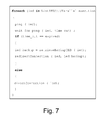
- FIG. 7 shows a first program element in accordance with an exemplary embodiment of the disclosure.
- a program element that can be executed by the control logic 48 of the command redirection device 38 .
- FIG. 7 illustrates the logic of the command redirection device 38 for the pinging task or pinging step.
- the command redirection device 38 regularly sends heartbeat signals to the main control device 20 a , 20 b , 20 c .
- the control devices are IEDs 20 a , 20 b , 20 c.
- the program element of FIG. 7 contains a loop that is executed in parallel for each IED of the plurality of IEDs of the process control system 24 , 24 ′.
- the addresses of the IEDs are stored in the list “ListIEDS”.
- the command redirection device 38 pings an IED “ied” and after that waits for a predefined time period “time_out” for an answer of the ping command.
- the command redirection device 38 If the command redirection device 38 does not receive the answer of the ping command after the time period “time_out”, the command redirection device sets the redirection. In this case, the command redirection device 38 retrieves the backup IED, for example with the aid of the database 42 and redirects the connection from the IED with the address “ied” to the IED with the address “ied_backup”. The command redirection device 38 is in the “faulty” state for the IED “ied”.
- redirection device 38 receives the answer from the pinged IED “ied”, a direct connection is set for the IED with the address “ied”. The command redirection device 38 is in the “normal” state for the IED “ied”.
- FIG. 8 shows a second program element in accordance with an exemplary embodiment of the disclosure.
- FIG. 8 shows an exemplary program element that can be executed by the control logic 48 of the command redirection device 38 .
- FIG. 8 represents the logic in the case of a control command in a normal state and faulty state.
- the function “sendToIED” is executed, when the command redirection device 38 receives a data packet comprising the control command “command”.
- FIG. 9 shows a third program element in accordance with an exemplary embodiment of the disclosure.
- FIG. 9 shows another exemplary program element that can be executed by the control logic 48 of the command redirection device 38 .
- FIG. 9 represents the logic in the case of a confirmation of a control operation or control command in a normal state and in a faulty state of the command redirection device 38 .
- the function “sendToSCADA” is executed, when the command redirection device 38 receives a data packet “confirmation” containing the confirmation of the control operation of one of the control devices 20 a , 20 b , 20 c , 30 a , 30 b , 30 c , 32 ′.
- the command redirection device 38 is in the faulty state, the source address or source IP of the confirmation is modified, i.e. the address of the backup control device is replaced by the address of the respective main control device.
- the confirmation is forwarded to the command device 40 via the interface 44 .
- the functional modules can be implemented as programmed software modules or procedures, respectively; however, one skilled in the art will understand that the functional modules can be implemented fully or partially in hardware.
Abstract
Description
- 10 substation automation system
- 12 interface to SCADA system
- 14 SCADA system
- 16 data bus, data network
- 18 a, 18 b, 18 c bay
- 20 a, 20 b, 20 c IED (main control device)
- 22 a, 22 b, 22 c primary equipment
- 24, 24′ process control system
- 26, 26′ primary system
- 28 a, 28 b protection device
- 30 a, 30 b redundant protection device
- 32 a, 32 b, 32 c redundant IED (backup control device)
- 34 a, 34 b protection module
- 36 a, 36 b redundant protection module
- 38 command redirection device
- 40 command device
- 32′ backup control device
- 42 database
- 44 first interface
- 46 second interface
- 48 control logic
Claims (18)
Applications Claiming Priority (4)
| Application Number | Priority Date | Filing Date | Title |
|---|---|---|---|
| EP09169253A EP2293159A1 (en) | 2009-09-02 | 2009-09-02 | Redundant control for a process control system |
| EP09169253.3 | 2009-09-02 | ||
| EP09169253 | 2009-09-02 | ||
| PCT/EP2010/062087 WO2011026734A1 (en) | 2009-09-02 | 2010-08-19 | Redundant control for a process control system |
Related Parent Applications (1)
| Application Number | Title | Priority Date | Filing Date |
|---|---|---|---|
| PCT/EP2010/062087 Continuation WO2011026734A1 (en) | 2009-09-02 | 2010-08-19 | Redundant control for a process control system |
Publications (2)
| Publication Number | Publication Date |
|---|---|
| US20120226367A1 US20120226367A1 (en) | 2012-09-06 |
| US9008809B2 true US9008809B2 (en) | 2015-04-14 |
Family
ID=42200945
Family Applications (1)
| Application Number | Title | Priority Date | Filing Date |
|---|---|---|---|
| US13/410,463 Active 2031-05-27 US9008809B2 (en) | 2009-09-02 | 2012-03-02 | Redundant control for a process control system |
Country Status (4)
| Country | Link |
|---|---|
| US (1) | US9008809B2 (en) |
| EP (1) | EP2293159A1 (en) |
| CN (1) | CN102483611B (en) |
| WO (1) | WO2011026734A1 (en) |
Cited By (2)
| Publication number | Priority date | Publication date | Assignee | Title |
|---|---|---|---|---|
| US20130254151A1 (en) * | 2010-12-17 | 2013-09-26 | Abb Research Ltd. | Systems and Methods for Predicting Customer Compliance with Demand Response Requests |
| US10810135B2 (en) * | 2017-01-26 | 2020-10-20 | Huawei Technologies Co., Ltd. | Data transmission method, apparatus, device, and system |
Families Citing this family (13)
| Publication number | Priority date | Publication date | Assignee | Title |
|---|---|---|---|---|
| JP5661659B2 (en) * | 2012-02-03 | 2015-01-28 | 株式会社日立製作所 | Plant monitoring control device and plant monitoring control method |
| CN107003644B (en) * | 2014-06-26 | 2020-10-02 | Abb瑞士股份有限公司 | Method for controlling a process plant using redundant local supervisory controllers |
| EP3026513B1 (en) * | 2014-11-28 | 2018-01-03 | Siemens Aktiengesellschaft | Redundant automation system and method for operating same |
| CN104467179A (en) * | 2014-11-29 | 2015-03-25 | 国网河南省电力公司南阳供电公司 | Automatic control anti-fault method for transformer substation |
| CN104580149B (en) * | 2014-12-02 | 2017-11-14 | 重庆晴彩科技有限公司 | A kind of active/standby mode network physical link is met an urgent need intelligent switching system |
| KR102485385B1 (en) * | 2016-05-10 | 2023-01-04 | 엘에스일렉트릭(주) | Scada system |
| CN107085439A (en) * | 2017-03-01 | 2017-08-22 | 江苏国电铁塔有限公司 | Photovoltaic tracking support array redundancy control method and control device |
| CN107994681A (en) * | 2017-05-24 | 2018-05-04 | 合肥万合科技信息服务有限公司 | A kind of transformer equipment Internet of Things integral intelligent monitors system |
| FR3067893A1 (en) | 2017-06-14 | 2018-12-21 | Overkiz | METHOD FOR CONFIGURING A DOMOTIC DEVICE BELONGING TO A DOMOTIC INSTALLATION |
| CN110647426B (en) * | 2018-06-27 | 2023-04-11 | 龙芯中科技术股份有限公司 | Dual-computer hot backup method, device and system and computer storage medium |
| CN109306875B (en) * | 2018-09-25 | 2021-02-09 | 中国船舶重工集团公司第七0三研究所 | Steam turbine DEH dual-controller synchronous hot standby redundancy switching device and method |
| CN109831331A (en) * | 2019-01-31 | 2019-05-31 | 北京淳中科技股份有限公司 | Signal processing system and its working method, electronic equipment and readable storage medium storing program for executing |
| CN109739202B (en) * | 2019-02-19 | 2020-10-16 | 西门子工厂自动化工程有限公司 | Production management system |
Citations (7)
| Publication number | Priority date | Publication date | Assignee | Title |
|---|---|---|---|---|
| US4141066A (en) | 1977-09-13 | 1979-02-20 | Honeywell Inc. | Process control system with backup process controller |
| EP0478288A2 (en) | 1990-09-26 | 1992-04-01 | Honeywell Inc. | Universal scheme of input/output redundancy in a process control system |
| US6173312B1 (en) | 1996-07-09 | 2001-01-09 | Hitachi, Ltd. | System for reliably connecting a client computer to a server computer |
| US6591150B1 (en) | 1999-09-03 | 2003-07-08 | Fujitsu Limited | Redundant monitoring control system, monitoring control apparatus therefor and monitored control apparatus |
| US20070206644A1 (en) * | 2006-03-02 | 2007-09-06 | Abb Technology Ag | Remote terminal unit and monitoring, protection and control of power systems |
| US20070270984A1 (en) * | 2004-10-15 | 2007-11-22 | Norbert Lobig | Method and Device for Redundancy Control of Electrical Devices |
| US7437203B2 (en) * | 1997-10-13 | 2008-10-14 | Viserge Limited | Remote terminal unit assembly |
Family Cites Families (2)
| Publication number | Priority date | Publication date | Assignee | Title |
|---|---|---|---|---|
| CN100451881C (en) * | 2006-12-08 | 2009-01-14 | 清华大学 | Double generator redundancy control system |
| CN101447890B (en) * | 2008-04-15 | 2011-11-30 | 中兴通讯股份有限公司 | Improved application server disaster tolerance system of next generation network and method thereof |
-
2009
- 2009-09-02 EP EP09169253A patent/EP2293159A1/en not_active Ceased
-
2010
- 2010-08-19 CN CN201080039706.9A patent/CN102483611B/en active Active
- 2010-08-19 WO PCT/EP2010/062087 patent/WO2011026734A1/en active Application Filing
-
2012
- 2012-03-02 US US13/410,463 patent/US9008809B2/en active Active
Patent Citations (8)
| Publication number | Priority date | Publication date | Assignee | Title |
|---|---|---|---|---|
| US4141066A (en) | 1977-09-13 | 1979-02-20 | Honeywell Inc. | Process control system with backup process controller |
| EP0478288A2 (en) | 1990-09-26 | 1992-04-01 | Honeywell Inc. | Universal scheme of input/output redundancy in a process control system |
| US5202822A (en) | 1990-09-26 | 1993-04-13 | Honeywell Inc. | Universal scheme of input/output redundancy in a process control system |
| US6173312B1 (en) | 1996-07-09 | 2001-01-09 | Hitachi, Ltd. | System for reliably connecting a client computer to a server computer |
| US7437203B2 (en) * | 1997-10-13 | 2008-10-14 | Viserge Limited | Remote terminal unit assembly |
| US6591150B1 (en) | 1999-09-03 | 2003-07-08 | Fujitsu Limited | Redundant monitoring control system, monitoring control apparatus therefor and monitored control apparatus |
| US20070270984A1 (en) * | 2004-10-15 | 2007-11-22 | Norbert Lobig | Method and Device for Redundancy Control of Electrical Devices |
| US20070206644A1 (en) * | 2006-03-02 | 2007-09-06 | Abb Technology Ag | Remote terminal unit and monitoring, protection and control of power systems |
Non-Patent Citations (3)
| Title |
|---|
| European Search Report for EP 09169253 dated Sep. 21, 2010. |
| International Preliminary Report on Patentability and Written Opinion (PCT/IB/373 and PCT/ISA/237) issued on Mar. 6, 2012 by European Patent Office as the International Searching Authority for International Application No. PCT/EP2010/062087. |
| International Search Report (PCT/ISA/210) issued on Nov. 24, 2010, by European Patent Office as the International Searching Authority for International Application No. PCT/EP2010/062087. |
Cited By (3)
| Publication number | Priority date | Publication date | Assignee | Title |
|---|---|---|---|---|
| US20130254151A1 (en) * | 2010-12-17 | 2013-09-26 | Abb Research Ltd. | Systems and Methods for Predicting Customer Compliance with Demand Response Requests |
| US9171256B2 (en) * | 2010-12-17 | 2015-10-27 | ABA Research Ltd. | Systems and methods for predicting customer compliance with demand response requests |
| US10810135B2 (en) * | 2017-01-26 | 2020-10-20 | Huawei Technologies Co., Ltd. | Data transmission method, apparatus, device, and system |
Also Published As
| Publication number | Publication date |
|---|---|
| US20120226367A1 (en) | 2012-09-06 |
| CN102483611A (en) | 2012-05-30 |
| WO2011026734A1 (en) | 2011-03-10 |
| CN102483611B (en) | 2016-05-11 |
| EP2293159A1 (en) | 2011-03-09 |
Similar Documents
| Publication | Publication Date | Title |
|---|---|---|
| US9008809B2 (en) | Redundant control for a process control system | |
| US9484738B2 (en) | Operating a substation automation system | |
| EP1976177B1 (en) | Substation automation system with increased availability | |
| EP2203753B1 (en) | System level testing for substation automation systems | |
| US8433451B2 (en) | Substation automation with redundant protection | |
| US9166407B2 (en) | Implementing substation automation load transfer function | |
| CN101154108B (en) | Safety relay having independently testable contacts | |
| JP5433115B1 (en) | Process bus protection control system, merging unit and arithmetic unit | |
| KR100951773B1 (en) | Apparatus and method for goose message detecting | |
| CN104412543B (en) | Automatically configure the configuration module of the communication capacity of intelligent electronic device | |
| EP2090950A1 (en) | Critical device with increased availability | |
| Apostolov | Efficient maintenance testing in digital substations based on IEC 61850 edition 2 | |
| EP3783764A1 (en) | Integration of primary protection relays for electric power delivery systems | |
| Falahati et al. | Failure modes in IEC 61850-enabled substation automation systems | |
| Daboul et al. | Testing protection relays based on IEC 61850 in substation automation systems | |
| Hunt et al. | SCADA communications for protection engineers | |
| Poștovei et al. | Aspects of Data Models compatibility within Substation hybrid LANs | |
| Noku et al. | Design of IEC61850 Based SCADA Operation for Automation of Upgraded Nkula Substation in Malawi | |
| Rim et al. | Multi-agent based reliability enhancement scheme for IEC61850 substation | |
| CN117175672A (en) | Direct-current power distribution network coordination control method and device, electronic equipment and storage medium | |
| Rim et al. | Multi agent-based on-line diagnostic scheme of substation ied. | |
| del Castillo et al. | 2012 Paris Session |
Legal Events
| Date | Code | Title | Description |
|---|---|---|---|
| AS | Assignment |
Owner name: ABB RESEARCH LTD, SWITZERLAND Free format text: ASSIGNMENT OF ASSIGNORS INTEREST;ASSIGNORS:TOURNIER, JEAN-CHARLES;WERNER, THOMAS;REEL/FRAME:028232/0379 Effective date: 20120326 |
|
| FEPP | Fee payment procedure |
Free format text: PAYOR NUMBER ASSIGNED (ORIGINAL EVENT CODE: ASPN); ENTITY STATUS OF PATENT OWNER: LARGE ENTITY |
|
| STCF | Information on status: patent grant |
Free format text: PATENTED CASE |
|
| MAFP | Maintenance fee payment |
Free format text: PAYMENT OF MAINTENANCE FEE, 4TH YEAR, LARGE ENTITY (ORIGINAL EVENT CODE: M1551); ENTITY STATUS OF PATENT OWNER: LARGE ENTITY Year of fee payment: 4 |
|
| AS | Assignment |
Owner name: ABB SCHWEIZ AG, SWITZERLAND Free format text: MERGER;ASSIGNOR:ABB RESEARCH LTD.;REEL/FRAME:051419/0309 Effective date: 20190416 |
|
| AS | Assignment |
Owner name: ABB POWER GRIDS SWITZERLAND AG, SWITZERLAND Free format text: ASSIGNMENT OF ASSIGNORS INTEREST;ASSIGNOR:ABB SCHWEIZ AG;REEL/FRAME:055589/0769 Effective date: 20201202 |
|
| AS | Assignment |
Owner name: HITACHI ENERGY SWITZERLAND AG, SWITZERLAND Free format text: CHANGE OF NAME;ASSIGNOR:ABB POWER GRIDS SWITZERLAND AG;REEL/FRAME:058666/0540 Effective date: 20211006 |
|
| MAFP | Maintenance fee payment |
Free format text: PAYMENT OF MAINTENANCE FEE, 8TH YEAR, LARGE ENTITY (ORIGINAL EVENT CODE: M1552); ENTITY STATUS OF PATENT OWNER: LARGE ENTITY Year of fee payment: 8 |
|
| AS | Assignment |
Owner name: HITACHI ENERGY LTD, SWITZERLAND Free format text: MERGER;ASSIGNOR:HITACHI ENERGY SWITZERLAND AG;REEL/FRAME:065549/0576 Effective date: 20231002 |