US8996730B1 - System and method to restore maximum payload size in a network adapter - Google Patents
System and method to restore maximum payload size in a network adapter Download PDFInfo
- Publication number
- US8996730B1 US8996730B1 US13/447,652 US201213447652A US8996730B1 US 8996730 B1 US8996730 B1 US 8996730B1 US 201213447652 A US201213447652 A US 201213447652A US 8996730 B1 US8996730 B1 US 8996730B1
- Authority
- US
- United States
- Prior art keywords
- adapter
- host
- mps
- driver
- value
- Prior art date
- Legal status (The legal status is an assumption and is not a legal conclusion. Google has not performed a legal analysis and makes no representation as to the accuracy of the status listed.)
- Active, expires
Links
Images


Classifications
-
- H—ELECTRICITY
- H04—ELECTRIC COMMUNICATION TECHNIQUE
- H04L—TRANSMISSION OF DIGITAL INFORMATION, e.g. TELEGRAPHIC COMMUNICATION
- H04L41/00—Arrangements for maintenance, administration or management of data switching networks, e.g. of packet switching networks
- H04L41/08—Configuration management of networks or network elements
- H04L41/0803—Configuration setting
- H04L41/0806—Configuration setting for initial configuration or provisioning, e.g. plug-and-play
-
- G—PHYSICS
- G06—COMPUTING; CALCULATING OR COUNTING
- G06F—ELECTRIC DIGITAL DATA PROCESSING
- G06F13/00—Interconnection of, or transfer of information or other signals between, memories, input/output devices or central processing units
- G06F13/38—Information transfer, e.g. on bus
- G06F13/382—Information transfer, e.g. on bus using universal interface adapter
- G06F13/385—Information transfer, e.g. on bus using universal interface adapter for adaptation of a particular data processing system to different peripheral devices
-
- H—ELECTRICITY
- H04—ELECTRIC COMMUNICATION TECHNIQUE
- H04L—TRANSMISSION OF DIGITAL INFORMATION, e.g. TELEGRAPHIC COMMUNICATION
- H04L41/00—Arrangements for maintenance, administration or management of data switching networks, e.g. of packet switching networks
- H04L41/08—Configuration management of networks or network elements
- H04L41/0803—Configuration setting
-
- G—PHYSICS
- G06—COMPUTING; CALCULATING OR COUNTING
- G06F—ELECTRIC DIGITAL DATA PROCESSING
- G06F2213/00—Indexing scheme relating to interconnection of, or transfer of information or other signals between, memories, input/output devices or central processing units
- G06F2213/0026—PCI express
Definitions
- the present invention relates to network adapters.
- Computing systems communicate with other devices using adapters, e.g. host bus adapters, network interface cards or adapters that can handle both network and storage traffic.
- a computing system may also be referred to as “host system” sets up various parameters for transfer of data between the host system and other devices via the adapter.
- One such parameter is a maximum payload size (MPS).
- MPS defines a maximum size of a payload, typically in bytes, that can be transmitted between the host system and the adapter.
- the adapter typically uses a default MPS value.
- the default MPS value may be different from the MPS value that is used by the host system to transfer data.
- the host system may change the default MPS value of the adapter to the value that is used by the host system.
- the host system may switch to a mode when minimal functionality of the host system is maintained.
- the host system may disable the adapter, for example, to conserve energy.
- the host system instructs the adapter to be enabled.
- the host system When the adapter is disabled, the host system performs a reset operation. During the reset operation, the adapter MPS value may be reset to the default MPS value. When the adapter is enabled, the host MPS value and the adapter MPS value will be different. The mismatch in the host MPS value and adapter MPS value may cause errors during data transfer between the host system and the adapter. Continuous efforts are being made to reduce errors during data transfer.
- a machine-implemented method includes storing a host maximum payload size (MPS) value of a host system as an adapter MPS value for an adapter operationally coupled to the host system; storing a host identifier at the adapter for identifying the host system; setting an adapter MPS value to the host MPS value; resetting the adapter MPS value to a default value after an event; and restoring the adapter MPS value to the host MPS value when the host identifier stored at the adapter matches with a host identifier value stored by the host system.
- MPS host maximum payload size
- a machine implemented method includes comparing if a host system identifier for a host system matches with a host system identifier stored at an adapter operationally coupled to the host system for sending and receiving information; storing a host maximum payload size (MPS) value of a host system as an adapter MPS value for the adapter; and restoring the adapter MPS value to the host MPS value after an event that resets the adapter MPS value to a default value that is different from the host identifier MPS value.
- MPS host maximum payload size
- a system in yet another embodiment, includes a host system having a first memory location for storing a host maximum payload size (MPS) value and a second memory location for storing a host identifier for uniquely identifying the host system.
- MPS host maximum payload size
- the system further includes an adapter operationally coupled to the host system and having a first adapter memory location for storing the host identifier value that identifies the host system; a second adapter memory location for storing an adapter MPS value that matches the host MPS value; and a third memory location that stores an adapter MPS value when the adapter is initialized. After the adapter is reset due to an event, the third memory location value is set to the host MPS value when the host identifier stored at the first adapter memory location matches with the host identifier stored at the second memory location of the host system.
- FIG. 1A shows a block diagram of a PCI-Express system
- FIG. 1B shows a block diagram of a system for sending and receiving information, according to one embodiment
- FIG. 2 shows an example of a software architecture used by the system of FIG. 1B ;
- FIG. 3 shows an initialization process for setting a maximum payload size value for an adapter
- FIG. 4 shows an example of an adapter driver installation process according to one embodiment
- FIG. 5 shows a data transfer process, according to one embodiment.
- a device and method is provided to maintain a consistent maximum payload size (“MPS”) value for both an adapter and a computing system. As described below, this enables robust design and reliable operations involving peripheral devices.
- MPS maximum payload size
- any of the embodiments described with reference to the figures may be implemented using software, firmware, hardware (e.g., fixed logic circuitry), manual processing, or a combination of these implementations.
- the terms “logic,” “module,” “component,” “system” and “functionality,” as used herein, generally represent software, firmware, hardware, or a combination of these elements.
- the terms “logic”, “module”, “component”, “system”, and “functionality” represent program code that performs specified tasks when executed on a processing device or devices (e.g., CPU or CPUs).
- the program code can be stored in one or more computer readable memory devices.
- the illustrated separation of logic, modules, components, systems, and functionality into distinct units may reflect an actual physical grouping and allocation of software, firmware, and/or hardware, or can correspond to a conceptual allocation of different tasks performed by a single software program, firmware program, and/or hardware unit.
- the illustrated logic, modules, components, systems, and functionality may be located at a single site (e.g., as implemented by a processing device), or may be distributed over a plurality of locations.
- machine-readable media refers to any kind of medium for retaining information in any form, including various kinds of storage devices (magnetic, optical, static, etc.).
- Machine-readable media also encompasses transitory forms for representing information, including various hardwired and/or wireless links for transmitting the information from one point to another.
- the embodiments disclosed herein may be implemented as a computer process (method), a computing system, or as an article of manufacture, such as a computer program product or computer-readable media.
- the computer program product may be computer storage media, readable by a computer device, and encoding a computer program of instructions for executing a computer process.
- the computer program product may also be a propagated signal on a carrier, readable by a computing system, and encoding a computer program of instructions for executing a computer process.
- FIG. 1A shows a top-level block diagram of a system 10 A that includes an upstream PCI-Express device 10 that communicates with a storage system 14 via a downstream PCI-Express device 12 .
- Upstream PCI-Express link (or path) 11 A is used for communication from downstream PCI-Express device 12 to upstream device 10 ; while downstream link (or path) 11 B is used for communication from upstream device 10 to downstream PCI-Express device 12 .
- PCI-Express links 11 A and 11 B comply with the PCI-Express standard that defines a standard interface incorporating PCI transaction protocols developed to offer better performance than the PCI or PCI-X bus standards.
- PCI Peripheral Component Interconnect
- PCI-X is another standard bus that is compatible with existing PCI cards using the PCI bus. It is noteworthy that the various embodiments disclosed herein are not limited to any particular industry standard or specification.
- Downstream PCI-Express device 12 communicates with a storage system 14 via link 13 .
- Link 13 may be any link, for example, a Fibre Channel link.
- Upstream device 10 may be a computing system (may also be referred to as a host system) and downstream PCI-Express device 12 may be an adapter (may also be referred to as a host bus adapter (HBA) and/or “controller”), as described below.
- HBA host bus adapter
- controller controller
- FIG. 1B shows a block diagram of a system 100 for sending and receiving information from other devices.
- System 100 may include a computing system 102 (also known as “host system” or “host”) and an adapter 122 .
- Adapter 122 interfaces between host system 100 and other devices (not shown) via a link 138 .
- Host system 102 may include one or more processors 104 (jointly referred to as processor 104 ), also known as a central processing unit (CPU), interfacing with other components via a bus 110 .
- Bus 110 may be, for example, a system bus, a Peripheral Component Interconnect (PCI) bus (or PCI Express bus), a HyperTransport or industry standard architecture (ISA) bus, a SCSI bus, a universal serial bus (USB), an Institute of Electrical and Electronics Engineers (IEEE) standard 1394 bus (sometimes referred to as “Firewire”), or any other kind of bus.
- PCI Peripheral Component Interconnect
- ISA HyperTransport or industry standard architecture
- SCSI SCSI
- USB universal serial bus
- IEEE Institute of Electrical and Electronics Engineers
- IEEE Institute of Electrical and Electronics Engineers
- Host system 102 may include or may have access to a mass storage device 109 , which may be for example a hard disk, a CD-ROM, a non-volatile memory device (flash or memory stick) or any other device.
- Storage 109 may store processor executable instructions and data, for example, operating system program files, application program files, and other files.
- Host system 102 interfaces with memory 106 that may include random access main memory (RAM), and/or read only memory (ROM).
- memory 106 may include random access main memory (RAM), and/or read only memory (ROM).
- RAM random access main memory
- ROM read only memory
- the processor 104 may store and execute the process steps out of memory 106 .
- ROM may store invariant instruction sequences, such as start-up instruction sequences or basic input/output operating system (BIOS) sequences for operation of a keyboard (not shown).
- BIOS basic input/output operating system
- the host system 102 may also include other devices and interfaces 108 , which may include a display device interface, a keyboard interface, a pointing device interface and others.
- Host system 102 also interfaces with a peripheral interface 112 via bus 110 .
- the peripheral interface 112 is coupled to a “root complex” 114 .
- Root complex 114 as defined by the PCI Express standard is an entity that includes a Host Bridge and one or more Root Ports.
- the Host Bridge connects a CPU to a Hierarchy, where a Hierarchy is a tree structure based on a PCI Express topology.
- the Root complex 114 connects to a standard PCI Express switch 115 that couples to adapter 122 , via a bus (or link) 118 , which in this case may be a PCI Express bus.
- Host processor 104 may communicate with adapter 122 via switch 115 . It is noteworthy that the path between root complex 114 and adapter 122 can also be a direct path with no switch, or can include multiple cascaded switches.
- the root complex 114 may include a host MPS (Maximum Payload Size) register 116 or any other type of storage location.
- the host MPS register 116 stores a host MPS value 117 that indicates the MPS size used by host system 102 to send information to adapter 122 .
- the host system 102 is uniquely identified by using a host identifier (“host Id”) 113 .
- the host Id 113 can vary in formation, for example, host Id 113 may be a unique host name, a unique identification value, a system serial number or any other format that can be used to uniquely identify host system 102 .
- host Id 113 may be coded and stored in a register (not shown) and is readable by processor 104 .
- the host Id 113 is stored in memory 106 .
- the host Id 113 can be programmed by programmable instructions, for example, by an operating system.
- Adapter 122 includes a processor 124 , a host interface 120 , a memory 126 , an adapter MPS register 134 (or storage location 134 ) and a port 136 .
- the host interface 120 is configured to interface with the host system 102 , via bus 118 .
- the structure and logic used by host interface 120 is designed to handle the protocol used by bus 118 . For example, if bus 118 is a PCI-Express link, then host interface 120 is able to handle PCI-Express protocol requirements when communicating with host system 102 .
- the adapter MPS register 134 , port 136 and memory 126 are accessible to adapter processor 124 .
- Memory 126 is used to store programmable instructions, for example, adapter firmware 128 .
- Adapter processor 124 executes firmware 128 to control the overall functionality of adapter 122 .
- Memory 126 may also include a storage location 130 that may be referred to as an adapter MPS store 130 to store an adapter MPS value 131 .
- the adapter MPS value 131 is set to be the same as the host MPS value 117 stored in host MPS register 116 .
- Memory 126 may also include another storage location 132 that may be referred to as a “host Id store 132 ” that is used to store a host Id value 133 .
- the host Id value 133 is set so that it is the same as host Id 113 stored at host system 102 .
- the adapter MPS register 134 can be used to store the adapter MPS register value 135 that is used by the adapter processor 124 to determine the payload size used by adapter 122 to transfer information.
- the use of adapter MPS value 135 is described below in more detail with respect to the process flow diagrams.
- Port 136 is used to send information to and receive information from other devices via link 138 .
- adapter 122 may be similar to a host bus adapter available from Qlogic Corporation.
- the adapter 122 may interface with fibre channel devices via link 138 .
- adapter 122 may be a Fibre Channel over Ethernet (FCOE) adapter that can handle both network and storage traffic.
- FCOE Fibre Channel over Ethernet
- FIG. 2 shows an example of a software architecture 200 used by system 100 of FIG. 1B .
- Software architecture 200 includes an operating system 202 for controlling overall host system 102 operations.
- the operating system 202 may be a Windows® based system provided by Microsoft Corp. or any other type, for example, a Linux® based operating system.
- one or more application 204 may be executed by host system 102 to communicate with other devices via adapter 122 .
- Application 204 communicates with firmware 128 via an adapter driver 206 .
- the adapter driver 206 may be executed by the host processor 104 and initiates communication with the adapter 122 , via bus 118 .
- the communication received from the host system 102 is decoded by the adapter processor 124 (or any other module) and appropriate instructions are executed by the adapter processor 124 or any other module affected by the instructions.
- the functionality of the various FIG. 2 modules is described below with respect to the process flow diagrams shown in FIGS. 3-5 .
- FIG. 3 shows an initialization process 300 where an error may be generated when different MPS values are used by host system 102 and adapter 122 .
- the process starts in block S 302 , when host system 102 and adapter 122 are powered up.
- BIOS Basic Input/Output System
- the adapter MPS value 135 is set to host MPS value, i.e., X1, at adapter MPS register 134 .
- operating system 202 is loaded and host system 102 starts functioning.
- adapter 122 is disabled.
- Adapter 122 may be disabled for various reasons, for example, adapter 122 may be disabled when operating system 202 instructs the host system 102 to switch to a hibernation mode. During hibernation mode to save power and resources, host system 102 may disable adapter 122 with other modules. In some embodiments, adapter 122 may simply be turned off.
- adapter 122 is enabled.
- the operating system 202 may instruct host system 102 to resume normal operations and enable adapter 122 .
- adapter 122 resets the adapter MPS value to its default value of X2. Because of the reset, the host MPS value and the adapter MPS value become different again.
- an error may occur during data transfer between the host system 102 and adapter 122 .
- the error may occur due to a mismatch in the host MPS value 117 , which is set to X1 and adapter MPS value 135 which is set to X2.
- the adaptive embodiments disclosed herein reduce these errors by using the same MPS value for both the adapter and the host system, as described below in more detail.
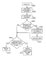
- FIG. 4 shows a process flow diagram for installing an adapter driver that reduces errors during data transfer between an adapter and a host system, according to one embodiment.
- the process begins in block S 400 when adapter driver 206 ( FIG. 2 ) is installed by host system 102 ( FIG. 1B ).
- host Id 113 identifying host system 102 is saved.
- the host Id can be any indicia that may uniquely identify the host system.
- the host Id may be a host name, a unique identifier value, a unique serial number and others.
- driver 206 determines the host Id 113 by polling or reading a specific storage location in host system 102 .
- driver 206 is loaded and system information is read from a registry (not shown).
- Driver 206 may also issue commands to adapter 122 to read and retrieve configuration information from one or more memory locations of adapter 122 .
- driver 206 may read host Id value 133 and adapter MPS register value 135 ( FIG. 1B ).
- driver 206 determines if the host Id value 113 matches host Id value 133 stored by adapter 122 .
- driver 206 stores the host Id value 113 as a new host Id value 133 in adapter memory 126 in block S 408 .
- adapter 122 also saves the host MPS value 117 as adapter MPS value 131 .
- the driver also stores the host MPS value 117 at adapter MPS register 134 as adapter MPS register value 135 .
- the process then moves to block 5412 .
- driver 206 determines if the host MPS value 117 and the adapter MPS register value 135 are the same.
- driver 206 restores the adapter MPS register value 135 to the adapter MPS value 131 which is the same as host MPS value 117 .
- driver 206 instructs the adapter 122 to read the adapter MPS value 131 and write it at the adapter MPS register 134 . Because the adapter MPS value 131 is the same as the host MPS value 117 , the adapter MPS register value 135 is restored to the host MPS value 117 .
- driver continues to execute other steps in block S 416 to complete driver 206 installation and configuration.
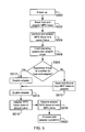
- FIG. 5 shows a process flow diagram for transferring data between adapter 122 and host system 102 , according to one embodiment.
- the process begins in block S 500 when system 100 ( FIG. 1B ) is powered up.
- the host MPS value 117 is read.
- the host MPS value 117 may be read from a root complex register 116 .
- the host MPS value 117 and the adapter MPS value 135 are both set to a same value, for example, X1.
- the operating system 202 and the adapter driver 206 FIG. 2
- FIG. 1B the operating system 202 and the adapter driver 206
- adapter driver 206 determines if the host Id 113 matches with the host Id 133 that is stored at adapter memory 126 . If the host Id 133 does not match with host Id 113 , then the host Id value 133 is replaced by the host Id value 113 maintained by host system 102 in block S 510 . In addition, the host MPS value 117 is stored as adapter MPS value 131 in adapter memory 126 . The host MPS value 117 is also stored as adapter MPS register value 135 at register 134 . Thereafter the process moves to block S 514 .
- adapter 122 is used to transfer information, until the process reaches block S 512 , when adapter 122 is disabled.
- adapter 122 may be disabled due to an event, for example, hibernation that is managed by operating system 202 .
- the host system 102 powers down various modules, including adapter 122 .
- the adapter is enabled.
- adapter 122 is enabled by an operating system event, for example, after hibernation.
- the adapter MPS register 134 is reset, as part of adapter initialization.
- adapter 122 resets the adapter MPS register value 135 to a default value, for example, X2.
- the adapter MPS register value 135 is restored to the host MPS value 117 stored at memory location 130 . Thereafter, in block S 520 , adapter 122 begins data transfer. Because the host MPS value and the adapter MPS values are the same, data transfer proceeds without any errors.
- robust data transfer occurs between a host system and an adapter, even if the adapter is disabled and then enabled by an external event, for example, an operating system initiated hibernation.
- an adapter with a first MPS value can be swapped with another adapter that may have a different MPS value.
- the system and method disclosed herein recognizes the change, by detecting a mismatch in the host Id and then, setting the proper MPS values that match with the host MPS value.
Abstract
Description
Claims (20)
Priority Applications (1)
| Application Number | Priority Date | Filing Date | Title |
|---|---|---|---|
| US13/447,652 US8996730B1 (en) | 2009-06-17 | 2012-04-16 | System and method to restore maximum payload size in a network adapter |
Applications Claiming Priority (3)
| Application Number | Priority Date | Filing Date | Title |
|---|---|---|---|
| US18790609P | 2009-06-17 | 2009-06-17 | |
| US12/817,707 US8185664B1 (en) | 2009-06-17 | 2010-06-17 | System and method to restore maximum payload size in a network adapter |
| US13/447,652 US8996730B1 (en) | 2009-06-17 | 2012-04-16 | System and method to restore maximum payload size in a network adapter |
Related Parent Applications (1)
| Application Number | Title | Priority Date | Filing Date |
|---|---|---|---|
| US12/817,707 Continuation US8185664B1 (en) | 2009-06-17 | 2010-06-17 | System and method to restore maximum payload size in a network adapter |
Publications (1)
| Publication Number | Publication Date |
|---|---|
| US8996730B1 true US8996730B1 (en) | 2015-03-31 |
Family
ID=46061365
Family Applications (2)
| Application Number | Title | Priority Date | Filing Date |
|---|---|---|---|
| US12/817,707 Active 2030-10-14 US8185664B1 (en) | 2009-06-17 | 2010-06-17 | System and method to restore maximum payload size in a network adapter |
| US13/447,652 Active 2031-11-01 US8996730B1 (en) | 2009-06-17 | 2012-04-16 | System and method to restore maximum payload size in a network adapter |
Family Applications Before (1)
| Application Number | Title | Priority Date | Filing Date |
|---|---|---|---|
| US12/817,707 Active 2030-10-14 US8185664B1 (en) | 2009-06-17 | 2010-06-17 | System and method to restore maximum payload size in a network adapter |
Country Status (1)
| Country | Link |
|---|---|
| US (2) | US8185664B1 (en) |
Cited By (1)
| Publication number | Priority date | Publication date | Assignee | Title |
|---|---|---|---|---|
| CN108712290A (en) * | 2018-05-25 | 2018-10-26 | 北京无线电测量研究所 | network card driving method, device and storage medium |
Families Citing this family (6)
| Publication number | Priority date | Publication date | Assignee | Title |
|---|---|---|---|---|
| US9264384B1 (en) | 2004-07-22 | 2016-02-16 | Oracle International Corporation | Resource virtualization mechanism including virtual host bus adapters |
| US9813283B2 (en) | 2005-08-09 | 2017-11-07 | Oracle International Corporation | Efficient data transfer between servers and remote peripherals |
| US9973446B2 (en) | 2009-08-20 | 2018-05-15 | Oracle International Corporation | Remote shared server peripherals over an Ethernet network for resource virtualization |
| US9331963B2 (en) | 2010-09-24 | 2016-05-03 | Oracle International Corporation | Wireless host I/O using virtualized I/O controllers |
| US9083550B2 (en) | 2012-10-29 | 2015-07-14 | Oracle International Corporation | Network virtualization over infiniband |
| US11614986B2 (en) * | 2018-08-07 | 2023-03-28 | Marvell Asia Pte Ltd | Non-volatile memory switch with host isolation |
Citations (7)
| Publication number | Priority date | Publication date | Assignee | Title |
|---|---|---|---|---|
| US6229538B1 (en) | 1998-09-11 | 2001-05-08 | Compaq Computer Corporation | Port-centric graphic representations of network controllers |
| US20010034799A1 (en) | 2000-04-25 | 2001-10-25 | Matsushita Electric Industrial Co., Ltd. | Packet transmission/reception processor |
| US6615282B1 (en) * | 1999-05-21 | 2003-09-02 | Intel Corporation | Adaptive messaging |
| US6721805B1 (en) | 1998-11-12 | 2004-04-13 | International Business Machines Corporation | Providing shared-medium multiple access capability in point-to-point communications |
| US6934768B1 (en) | 2000-10-23 | 2005-08-23 | International Business Machines Corporation | Dynamic modification of fragmentation size cluster communication parameter in clustered computer system |
| US7085855B1 (en) | 1999-10-15 | 2006-08-01 | Seiko Epson Corporation | Data transfer control device and electronic equipment |
| US20100064080A1 (en) * | 2008-09-11 | 2010-03-11 | International Business Machines Corporation | Managing pci-express max payload size for legacy operating systems |
-
2010
- 2010-06-17 US US12/817,707 patent/US8185664B1/en active Active
-
2012
- 2012-04-16 US US13/447,652 patent/US8996730B1/en active Active
Patent Citations (8)
| Publication number | Priority date | Publication date | Assignee | Title |
|---|---|---|---|---|
| US6229538B1 (en) | 1998-09-11 | 2001-05-08 | Compaq Computer Corporation | Port-centric graphic representations of network controllers |
| US6721805B1 (en) | 1998-11-12 | 2004-04-13 | International Business Machines Corporation | Providing shared-medium multiple access capability in point-to-point communications |
| US6615282B1 (en) * | 1999-05-21 | 2003-09-02 | Intel Corporation | Adaptive messaging |
| US20030200363A1 (en) * | 1999-05-21 | 2003-10-23 | Futral William T. | Adaptive messaging |
| US7085855B1 (en) | 1999-10-15 | 2006-08-01 | Seiko Epson Corporation | Data transfer control device and electronic equipment |
| US20010034799A1 (en) | 2000-04-25 | 2001-10-25 | Matsushita Electric Industrial Co., Ltd. | Packet transmission/reception processor |
| US6934768B1 (en) | 2000-10-23 | 2005-08-23 | International Business Machines Corporation | Dynamic modification of fragmentation size cluster communication parameter in clustered computer system |
| US20100064080A1 (en) * | 2008-09-11 | 2010-03-11 | International Business Machines Corporation | Managing pci-express max payload size for legacy operating systems |
Cited By (1)
| Publication number | Priority date | Publication date | Assignee | Title |
|---|---|---|---|---|
| CN108712290A (en) * | 2018-05-25 | 2018-10-26 | 北京无线电测量研究所 | network card driving method, device and storage medium |
Also Published As
| Publication number | Publication date |
|---|---|
| US8185664B1 (en) | 2012-05-22 |
Similar Documents
| Publication | Publication Date | Title |
|---|---|---|
| US8996730B1 (en) | System and method to restore maximum payload size in a network adapter | |
| US10114658B2 (en) | Concurrent testing of PCI express devices on a server platform | |
| US10353779B2 (en) | Systems and methods for detection of firmware image corruption and initiation of recovery | |
| US8499104B2 (en) | Method for switching working mode, USB device, and host device | |
| US9569226B2 (en) | Baseboard management controller and method of loading firmware | |
| US9652351B2 (en) | System to detect charger and remote host for type-C connector | |
| US8838865B2 (en) | Hot plug ad hoc computer resource allocation | |
| US8671228B1 (en) | System and methods for managing virtual adapter instances | |
| US9880858B2 (en) | Systems and methods for reducing BIOS reboots | |
| CN112540785A (en) | Firmware upgrading method of storage device, control equipment and storage device | |
| CN110688235B (en) | System and method for sharing wireless connection information between UEFI firmware and OS | |
| US20150186317A1 (en) | Method and apparatus for detecting the initiator/target orientation of a smart bridge | |
| US20200104140A1 (en) | Systems and methods for identifying and protection of boot storage devices | |
| US10996942B1 (en) | System and method for graphics processing unit firmware updates | |
| US11016923B1 (en) | Configuring hot-inserted device via management controller | |
| US20170124004A1 (en) | Firmware configuration through emulated commands | |
| US10439934B2 (en) | Systems and methods for addressing multiple physical and virtual functions in network controller-sideband interface | |
| US7962675B1 (en) | Method and system for communicating with a host bus adapter | |
| EP2477120B1 (en) | Method for processing device connection, combination device and host device | |
| US10275261B1 (en) | Methods and systems for message logging and retrieval in computer systems | |
| US11366673B1 (en) | Managing transitioning of computing system to power-on state from standby-power state | |
| US11953974B2 (en) | Method for PCIe fallback in a CXL system | |
| US11307844B2 (en) | System and method for intelligent power management of firmware updates | |
| US11755518B2 (en) | Control of Thunderbolt/DisplayPort multiplexor for discrete USB-C graphics processor | |
| US11507274B2 (en) | System and method to use dictionaries in LZ4 block format compression |
Legal Events
| Date | Code | Title | Description |
|---|---|---|---|
| AS | Assignment |
Owner name: QLOGIC, CORPORATION, CALIFORNIA Free format text: ASSIGNMENT OF ASSIGNORS INTEREST;ASSIGNORS:LOK, YING P.;MITTAL, ARUN;POLICAN, LINGLING;AND OTHERS;SIGNING DATES FROM 20100615 TO 20100616;REEL/FRAME:035042/0260 |
|
| STCF | Information on status: patent grant |
Free format text: PATENTED CASE |
|
| CC | Certificate of correction | ||
| AS | Assignment |
Owner name: JPMORGAN CHASE BANK, N.A., AS COLLATERAL AGENT, IL Free format text: SECURITY AGREEMENT;ASSIGNOR:QLOGIC CORPORATION;REEL/FRAME:041854/0119 Effective date: 20170228 |
|
| AS | Assignment |
Owner name: CAVIUM, INC., CALIFORNIA Free format text: MERGER;ASSIGNOR:QLOGIC CORPORATION;REEL/FRAME:044812/0504 Effective date: 20160615 |
|
| AS | Assignment |
Owner name: QLOGIC CORPORATION, CALIFORNIA Free format text: RELEASE BY SECURED PARTY;ASSIGNOR:JP MORGAN CHASE BANK, N.A., AS COLLATERAL AGENT;REEL/FRAME:046496/0001 Effective date: 20180706 Owner name: CAVIUM, INC, CALIFORNIA Free format text: RELEASE BY SECURED PARTY;ASSIGNOR:JP MORGAN CHASE BANK, N.A., AS COLLATERAL AGENT;REEL/FRAME:046496/0001 Effective date: 20180706 Owner name: CAVIUM NETWORKS LLC, CALIFORNIA Free format text: RELEASE BY SECURED PARTY;ASSIGNOR:JP MORGAN CHASE BANK, N.A., AS COLLATERAL AGENT;REEL/FRAME:046496/0001 Effective date: 20180706 |
|
| MAFP | Maintenance fee payment |
Free format text: PAYMENT OF MAINTENANCE FEE, 4TH YEAR, LARGE ENTITY (ORIGINAL EVENT CODE: M1551); ENTITY STATUS OF PATENT OWNER: LARGE ENTITY Year of fee payment: 4 |
|
| AS | Assignment |
Owner name: CAVIUM, LLC, CALIFORNIA Free format text: CHANGE OF NAME;ASSIGNOR:CAVIUM, INC.;REEL/FRAME:047205/0953 Effective date: 20180921 |
|
| AS | Assignment |
Owner name: CAVIUM INTERNATIONAL, CAYMAN ISLANDS Free format text: ASSIGNMENT OF ASSIGNORS INTEREST;ASSIGNOR:CAVIUM, LLC;REEL/FRAME:051948/0807 Effective date: 20191231 |
|
| AS | Assignment |
Owner name: MARVELL ASIA PTE, LTD., SINGAPORE Free format text: ASSIGNMENT OF ASSIGNORS INTEREST;ASSIGNOR:CAVIUM INTERNATIONAL;REEL/FRAME:053179/0320 Effective date: 20191231 |
|
| MAFP | Maintenance fee payment |
Free format text: PAYMENT OF MAINTENANCE FEE, 8TH YEAR, LARGE ENTITY (ORIGINAL EVENT CODE: M1552); ENTITY STATUS OF PATENT OWNER: LARGE ENTITY Year of fee payment: 8 |