US8996282B2 - Fueling systems, methods and apparatus for an internal combustion engine - Google Patents
Fueling systems, methods and apparatus for an internal combustion engine Download PDFInfo
- Publication number
- US8996282B2 US8996282B2 US13/198,943 US201113198943A US8996282B2 US 8996282 B2 US8996282 B2 US 8996282B2 US 201113198943 A US201113198943 A US 201113198943A US 8996282 B2 US8996282 B2 US 8996282B2
- Authority
- US
- United States
- Prior art keywords
- fueling
- value
- values
- engine
- index
- Prior art date
- Legal status (The legal status is an assumption and is not a legal conclusion. Google has not performed a legal analysis and makes no representation as to the accuracy of the status listed.)
- Active, expires
Links
Images


Classifications
-
- F—MECHANICAL ENGINEERING; LIGHTING; HEATING; WEAPONS; BLASTING
- F02—COMBUSTION ENGINES; HOT-GAS OR COMBUSTION-PRODUCT ENGINE PLANTS
- F02D—CONTROLLING COMBUSTION ENGINES
- F02D41/00—Electrical control of supply of combustible mixture or its constituents
- F02D41/30—Controlling fuel injection
- F02D41/38—Controlling fuel injection of the high pressure type
- F02D41/40—Controlling fuel injection of the high pressure type with means for controlling injection timing or duration
-
- F—MECHANICAL ENGINEERING; LIGHTING; HEATING; WEAPONS; BLASTING
- F02—COMBUSTION ENGINES; HOT-GAS OR COMBUSTION-PRODUCT ENGINE PLANTS
- F02D—CONTROLLING COMBUSTION ENGINES
- F02D41/00—Electrical control of supply of combustible mixture or its constituents
- F02D41/02—Circuit arrangements for generating control signals
- F02D41/14—Introducing closed-loop corrections
- F02D41/1438—Introducing closed-loop corrections using means for determining characteristics of the combustion gases; Sensors therefor
- F02D41/1444—Introducing closed-loop corrections using means for determining characteristics of the combustion gases; Sensors therefor characterised by the characteristics of the combustion gases
- F02D41/1454—Introducing closed-loop corrections using means for determining characteristics of the combustion gases; Sensors therefor characterised by the characteristics of the combustion gases the characteristics being an oxygen content or concentration or the air-fuel ratio
- F02D41/1455—Introducing closed-loop corrections using means for determining characteristics of the combustion gases; Sensors therefor characterised by the characteristics of the combustion gases the characteristics being an oxygen content or concentration or the air-fuel ratio with sensor resistivity varying with oxygen concentration
-
- F—MECHANICAL ENGINEERING; LIGHTING; HEATING; WEAPONS; BLASTING
- F02—COMBUSTION ENGINES; HOT-GAS OR COMBUSTION-PRODUCT ENGINE PLANTS
- F02D—CONTROLLING COMBUSTION ENGINES
- F02D41/00—Electrical control of supply of combustible mixture or its constituents
- F02D41/24—Electrical control of supply of combustible mixture or its constituents characterised by the use of digital means
- F02D41/2406—Electrical control of supply of combustible mixture or its constituents characterised by the use of digital means using essentially read only memories
- F02D41/2425—Particular ways of programming the data
- F02D41/2429—Methods of calibrating or learning
- F02D41/2451—Methods of calibrating or learning characterised by what is learned or calibrated
-
- F—MECHANICAL ENGINEERING; LIGHTING; HEATING; WEAPONS; BLASTING
- F02—COMBUSTION ENGINES; HOT-GAS OR COMBUSTION-PRODUCT ENGINE PLANTS
- F02D—CONTROLLING COMBUSTION ENGINES
- F02D2200/00—Input parameters for engine control
- F02D2200/02—Input parameters for engine control the parameters being related to the engine
- F02D2200/10—Parameters related to the engine output, e.g. engine torque or engine speed
- F02D2200/101—Engine speed
-
- F—MECHANICAL ENGINEERING; LIGHTING; HEATING; WEAPONS; BLASTING
- F02—COMBUSTION ENGINES; HOT-GAS OR COMBUSTION-PRODUCT ENGINE PLANTS
- F02D—CONTROLLING COMBUSTION ENGINES
- F02D2200/00—Input parameters for engine control
- F02D2200/60—Input parameters for engine control said parameters being related to the driver demands or status
- F02D2200/602—Pedal position
-
- F—MECHANICAL ENGINEERING; LIGHTING; HEATING; WEAPONS; BLASTING
- F02—COMBUSTION ENGINES; HOT-GAS OR COMBUSTION-PRODUCT ENGINE PLANTS
- F02D—CONTROLLING COMBUSTION ENGINES
- F02D41/00—Electrical control of supply of combustible mixture or its constituents
- F02D41/02—Circuit arrangements for generating control signals
- F02D41/18—Circuit arrangements for generating control signals by measuring intake air flow
-
- Y—GENERAL TAGGING OF NEW TECHNOLOGICAL DEVELOPMENTS; GENERAL TAGGING OF CROSS-SECTIONAL TECHNOLOGIES SPANNING OVER SEVERAL SECTIONS OF THE IPC; TECHNICAL SUBJECTS COVERED BY FORMER USPC CROSS-REFERENCE ART COLLECTIONS [XRACs] AND DIGESTS
- Y02—TECHNOLOGIES OR APPLICATIONS FOR MITIGATION OR ADAPTATION AGAINST CLIMATE CHANGE
- Y02T—CLIMATE CHANGE MITIGATION TECHNOLOGIES RELATED TO TRANSPORTATION
- Y02T10/00—Road transport of goods or passengers
- Y02T10/10—Internal combustion engine [ICE] based vehicles
- Y02T10/40—Engine management systems
-
- Y02T10/44—
Definitions
- the present disclosure relates to internal combustion engines, and more particularly, to improved fueling systems, methods and apparatus which may be used with a stratified charge.
- a conventional four-stroke Otto cycle engine may be understood to be fueled by drawing a mixture of air and fuel (e.g. gasoline) into a combustion chamber/cylinder of the engine during an intake stroke thereof, typically through a port of an intake manifold. This may produce a homogeneous charge of the air-fuel mixture within the combustion chamber/cylinder, kept particularly close to a stoichiometric air-fuel ratio, which may be ignited by an igniter (e.g. spark plug) near the top of a compression stroke of the engine.
- a mixture of air and fuel e.g. gasoline
- an igniter e.g. spark plug
- the air-fuel ratio may be understood as the mass ratio of air to fuel mixture introduced into the combustion chamber of an engine for combustion.
- gasoline used as a fuel
- the stoichiometric air-fuel ratio is generally understood to be approximately 14.7 to 1 or, stated another way, 14.7:1.
- the air and fuel are balanced such that exactly enough air is provided to completely burn all of the fuel. If there is less air than required to maintain the stoichiometric air-fuel mixture, then there will be excess fuel left over after combustion, which may be referred to as a rich air-fuel ratio.
- the air-fuel ratio may be commonly referred to in the trade, it should be understood that the air-fuel ratio may be more technically understood to be an oxygen-fuel ratio given that combustion is an oxidation process, and oxygen from the air is the oxidizer. However, while nitrogen and other elements in the air may not participate directly in combustion, such may have an effect on the oxidation rate.
- Rich mixtures may produce cooler combustion gas than a stoichiometric mixture, however may have poorer fuel efficiency and increased pollution in the form of unburned hydrocarbons and carbon monoxide which may not be completely removed by the catalytic converter.
- Slightly lean mixtures may produce less power than the stoichiometric mixture, cooler combustion gas and increased pollution in the form of nitrogen oxides.
- a stoichiometric mixture burns relatively hot, it may damage engine components if the engine is placed under high load at this fuel air mixture. Consequently, for acceleration and high load conditions, a richer mixture (lower air-fuel ratio) may be used to produce cooler combustion products.
- a homogeneous charge may be understood to provide stable combustion at a stoichiometric air-fuel ratio, but place limits on the engine's efficiency in running a lean mixture.
- Running at a lean mixture with a homogeneous charge may result in unstable combustion, which may lead to decreases in power and increases in hydrocarbon and carbon monoxide emissions.
- fuel may be directly injected into the combustion chamber/cylinder (also known as direct fuel injection or “DFI”), as opposed to being injected from an intake port of an intake manifold (also known as port fuel injection or “PFI”).
- DFI direct fuel injection
- PFI port fuel injection
- Direct fuel injection may be used to provide a homogeneous air-fuel mixture within the combustion chamber/cylinder of the engine. Direct fuel injection may also be used to provide a stratified air-fuel charge, which may be referred to as fuel stratified fuel injection or “SFI”. In contrast to port fuel injection, direct fuel injection may direct fuel towards the igniter, rather than elsewhere in the combustion chamber/cylinder, which may provide a stratified charge. In other words, an air-fuel charge in which the air-fuel ratio is not homogeneous throughout the combustion chamber/cylinder, but varies across a volume of the combustion chamber/cylinder with distance from the ignitor.
- Fuel injection timing may be understood to influence whether a direct injected air-fuel charge is homogeneous or stratified. For example, a homogeneous air-fuel charge may result when fuel is injected into the combustion chamber/cylinder of the engine during the intake stroke, while a stratified air-fuel charge may result when fuel is injected into the combustion chamber/cylinder of the engine during the compression stroke just before ignition.
- the internal combustion engine is configured to operate with a homogeneous air-fuel charge or a stratified air-fuel charge may be influenced by the operating load placed on the engine. For example, at low loads (e.g. constant or reducing speed with no acceleration), the engine may be operated with a stratified air-fuel charge, which may result in a lean burn and increased fuel economy. Alternatively, at moderate to high loads, the engine may be operated with a homogeneous air-fuel charge at near stoichiometric or slightly richer conditions.
- a diesel internal combustion engine may be understood to operate by stratified charge compression ignition (no ignitor or spark), where diesel fuel is injected into hot compressed (pressurized) air in the combustion chamber/cylinder of the engine during the compression stroke at the moment ignition is desired and self-ignites immediately.
- stratified charge compression ignition no ignitor or spark
- the present disclosure relates to internal combustion engines, and more particularly, to improved fueling systems, methods and apparatus which may be used with a stratified charge.
- the present disclosure describes systems, methods and apparatus to operate internal combustion engines, particularly stratified charge engines including direct injection gasoline and diesel engines, which may be particularly operated at a lean air-fuel ratio with exhaust gas recirculation (EGR).
- EGR exhaust gas recirculation
- control modes may include idle control mode (which may be identified as Mode 0), normal lean operation control mode (which may be identified as Mode 2), and normal rich operation control mode (which may be identified as Mode 3).
- idle control mode which may be identified as Mode 0
- normal lean operation control mode which may be identified as Mode 2
- normal rich operation control mode which may be identified as Mode 3
- Each of the various control modes may be understood to have different fueling considerations.
- engine fueling may be model based.
- Fueling parameters such as fuel quantity, injection timing and injection pressure may be determined from: (1) in-cylinder condition, which may be determined (calculated) with physical models using, for example, various sensors such as airflow mass, exhaust lambda, intake lambda, intake temperature, and coolant temperature sensors; (2) engine speed; and (3) accelerator pedal position.
- the fueling parameters may be indexed to a parameter k, which may be referred to as a fueling index k, so that a particular (single) value of the fueling index k defines all of the fueling parameters.
- the fueling index k may also be used to estimate the actual engine torque (defined as the torque representative TR).
- the fueling index k value may be temporarily determined by accelerator pedal position. Then, the fueling index k value may be revised using a predetermined fueling correction model. Selection of the fueling correction model may be dependent upon whether the engine is in an operating condition in which: (1) fuel injection quantity drives in-cylinder oxygen mass O2 or, stated another way, in-cylinder oxygen mass O2 is driven by fuel injection quantity, or (2) fuel injection quantity is driven by in-cylinder oxygen mass O2 or, stated another way, in-cylinder oxygen mass O2 drives fuel injection quantity.
- the present disclosure provides a method to operate an internal combustion engine comprising storing a fueling command map having fueling index values, each of the fueling index values defining values for a plurality of fueling parameters, and a plurality of predetermined non-linear relationships that directly relate fueling index values to in-cylinder oxygen mass values; determining a temporary fueling index value; determining an in-cylinder oxygen mass value; identifying a predetermined relationship that directly relates fueling index values to in-cylinder oxygen mass values from the plurality of predetermined relationships to provide an identified predetermined relationship; determining that a current relationship of the temporary fueling index value to the calculated oxygen mass value differs from the identified predetermined relationship; and adjusting the temporary fueling index value using at least one fueling correction model to provide a revised fueling index value that approaches the identified predetermined relationship.
- the present disclosure providers a method to operate an internal combustion engine of a motor vehicle, the method comprising storing a fueling command map having fueling index values, each of the fueling index values defining values for a plurality of fueling parameters, and a plurality of predetermined non-linear relationships that directly relate fueling index values to in-cylinder oxygen mass values; during an operation of the engine, receiving engine operating values representing accelerator pedal position, intake airflow mass, a concentration of oxygen in an intake charge and a concentration of oxygen in exhaust gas; determining a temporary fueling index value, wherein the temporary fueling index value is determined from at least one of the engine operating values representing the accelerator pedal position and a previous combustion cycle of the engine; determining an in-cylinder oxygen mass value, wherein the oxygen mass value is calculated at least in part from the engine operating values representing the intake airflow mass, the concentration of oxygen in the intake charge and the concentration of oxygen in the exhaust gas; identifying a predetermined relationship that directly relates fueling index values to in-cylinder oxygen mass values from the plurality of predetermined relationships
- FIG. 1 illustrates an exemplary engine having a fueling control module which may operate in accordance with the methods disclosed herein;
- FIG. 2 illustrates certain fueling and ignition parameters Q* may be packaged and indexed by indexes k and j;
- FIG. 3 illustrates an exemplary flow chart to operate an internal combustion engine of a motor vehicle, particularly by improved control of the fueling process to provide improved combustion;
- FIG. 4A illustrates a methodology to determine a temporary fueling index k temp value from pedal position P and expected torque TE;
- FIG. 4B illustrates a methodology to determine fuel quantity Q f from a fueling index k value
- FIG. 5 illustrates an exemplary relationship between expected torque TE (y-axis) versus accelerator pedal position P (x-axis) at various engine speeds;
- FIG. 6 illustrates exemplary relationships for in-cylinder oxygen mass O2 (y-axis) versus fueling index k value (x-axis) at various predetermined engine temperatures and application of a first fueling correction model;
- FIG. 7 illustrates various control zones 1 , 2 and 3 determined from in-cylinder oxygen mass O2 value (y-axis) versus fueling index k value (x-axis) during steady state;
- FIG. 8 illustrates an exemplary fuel quantity limitation to avoid unstable fuel quantity calculations
- FIG. 9 illustrates exemplary relationships for in-cylinder oxygen mass O2 (y-axis) versus fueling index k value (x-axis) at various predetermined engine temperatures and application of a second fueling correction model
- FIG. 10 illustrates a three-dimensional map comprising tables which map predetermined engine temperature values, fueling index k values and engine speed rpm to in-cylinder oxygen mass O2 values;
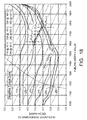
- FIG. 11 illustrates torque (y-axis) versus engine speed rpm (x-axis) and including a fuel injection pattern map with the overall range of fueling index k values segmented or grouped into smaller ranges, with each range corresponding to certain injection patterns;
- FIG. 12 illustrates fueling index k value (y-axis) versus in-cylinder oxygen mass O2 (x-axis) for various engine speeds rpm at predetermined engine temperature values of 75° C. and 90° C. and determination of the fueling index k value between 75° C. and 90° C.;
- FIG. 13 illustrates a three-dimensional map comprising tables which map predetermined engine temperature values, fueling index k values and engine speed rpm to intake oxygen concentration O2c values;
- FIG. 14 illustrates a three-dimensional map comprising tables which map predetermined engine temperature values, fueling index k values and engine speed rpm to fuel injection timing TFIN values;
- FIG. 15 illustrates the effect of intake oxygen concentration deviation ⁇ O2c and in-cylinder oxygen mass deviation ⁇ O2 on fuel injection timing (crank angle) offset;
- FIG. 16 illustrates a two-dimensional map comprising tables which map in-cylinder oxygen mass O2 deviation values and intake oxygen concentration deviation ⁇ O2c values to injection timing offset ⁇ values;
- FIG. 17 illustrates a two-dimensional map comprising tables which map fueling index k values and engine speed rpm to maximum injection timing offset ⁇ max values;
- FIG. 18 illustrates an exemplary relationship for in-cylinder oxygen mass O2 (y-axis) versus fueling index k value (x-axis) at various predetermined engine temperature values and application of a fueling correction model according to another embodiment of the disclosure.
- FIG. 19 illustrates an exemplary relationship for in-cylinder oxygen mass O2 (y-axis) versus fueling index k value (x-axis) at various predetermined engine temperature values and application of a fueling correction model according to another embodiment of the disclosure.
- the following disclosure relates to internal combustion engines, and more particularly, to improved fueling systems, methods and apparatus which may be used with a stratified charge.
- the following disclosure describes systems, methods and apparatus to operate internal combustion engines, particularly stratified charge engines including direct injection gasoline and diesel engines, which may be particularly operated at a lean air-fuel ratio with exhaust gas recirculation (EGR).
- EGR exhaust gas recirculation
- exhaust gas expelled from the cylinders of an internal combustion engine may be collected in a collector of an exhaust manifold. A fraction of the collected exhaust gas may then be routed from the exhaust manifold through a control valve back to an intake manifold of the engine, where it may be introduced to a stream of ambient air-fuel mixture.
- EGR may affect combustion in several ways. Notably, the combustion may be cooled by the presence of exhaust gas, that is, the recirculated exhaust gas may absorb heat of combustion. The dilution of the oxygen present in the combustion chamber with the exhaust gas, in combination with the cooler combustion, may reduce the production of nitrogen oxides (NO x ).
- NO x nitrogen oxides
- FIG. 1 illustrates an internal combustion engine 10 with which the systems, methods and apparatus described herein may be used.
- Engine 10 may include fuel injectors, which may include fuel injectors 14 for direct injection (i.e. an injector which injects directly into the cylinder/combustion chamber, which may be referred to as a direct fuel injector) or fuel injectors 18 for indirect injection (i.e. an injector which does not inject directly into the cylinder/combustion chamber, but rather generally before the intake valve 22 such as with intake port injection).
- Engine 10 may also include an EGR (exhaust gas recirculation) loop 30 and EGR valve 34 as known in the art.
- EGR exhaust gas recirculation
- Engine 10 may also include sensors for acquiring various input values relevant to the present disclosure, such as sensors configured to acquire input values representative of engine speed 38 , accelerator pedal position 42 , intake airflow mass 46 , concentration of oxygen in the intake charge 50 , concentration of oxygen in the exhaust gas 54 , intake manifold temperature 58 , and coolant temperature 62 .
- the various sensors may be suitably configured and arranged to perform their specific functions, including providing suitable signals as known by one of ordinary skill in the art.
- Engine 10 may further include an engine control unit (ECU) 66 and a separate fueling control module 70 .
- Either may be programmed to receive and process signals from the various sensors, and control various fueling parameters in accordance with the present disclosure.
- Either engine control unit 66 or fueling control module 70 may be a processor based unit including appropriate software and hardware, such as computer processing and memory devices, and the memory thereof may store maps of known values to fueling parameters for access during operation of engine 10 .
- Fueling control module 70 may be integrated with or part of a comprehensive engine controller, such as an engine control unit (ECU) 66 .
- fueling parameters for internal combustion engine 10 may be particularly defined using a unit-less fueling index k as described in greater detail below.
- the unit-less fuel index values, or k values may be established from empirical test data. For example, fueling parameters for engine 10 may be established which better optimize engine performance for a particular set of engine operating conditions (e.g. steady state conditions), while at the same time balancing a need to inhibit production of certain undesirable combustion by-products, such as unburnt hydrocarbons or nitrogen oxides.
- fueling parameters for a particular set of engine operating conditions may be established to achieve a particular air-to-fuel ratio, particularly taking into consideration the mass of oxygen in the cylinder of the engine 10 .
- a fueling index k value may be assigned to the given set of fueling parameters, thus defining values for a plurality of fueling parameters.
- the fueling index k values may then be stored in the fueling control module 25 , such as part of a fueling map.
- certain fueling parameters Q* such as for fuel injection quantity, timing and pressure (and ignition timing in the case of a gasoline engine) may be packaged and indexed by indexes k and j, with the index k being related to torque and the index j being related to engine speed.
- fueling parameters Q* are defined and the actual engine torque may be estimated, which may be referred to herein as the torque representative TR.
- the fueling index k may be particularly defined as to have values which monotonically increase with increasing torque ( FIG. 4A ), and the fueling parameter of fuel quantity Q f may be particularly defined as to have values which monotonically increase with increasing fueling index k values ( FIG. 4B ).
- FIG. 3 there is illustrated an exemplary process control flow chart 100 to control fueling and subsequent combustion in an internal combustion engine of a motor vehicle, particularly by improved control of the fueling process.
- fueling control module 25 may receive from various sensors, as shown at reference characters 110 and 115 , engine operating values which may represent, among others, engine speed rpm, accelerator pedal position P, intake airflow mass ma, a concentration of oxygen in an intake charge O2c, a concentration of oxygen in exhaust gas O2ce, engine intake manifold temperature Ti, and engine coolant temperature Tc.
- engine operating values which may represent, among others, engine speed rpm, accelerator pedal position P, intake airflow mass ma, a concentration of oxygen in an intake charge O2c, a concentration of oxygen in exhaust gas O2ce, engine intake manifold temperature Ti, and engine coolant temperature Tc.
- a predetermined temporary (pedal-based) fueling index k temp 120 value may be determined from a fueling map, which may be used to determine temporary fueling parameters such as fuel quantity Q f .
- the predetermined temporary (pedal-based) fueling index k temp 120 value may be determined after engine start-up.
- an intake manifold temperature sensor (voltage) signals may be used to determine an intake manifold temperature Ti, and from a coolant temperature sensor (voltage) signals to determine a coolant temperature Tc. From Ti and Tc, an engine temperature 125 , such as representative T*, may be calculated to provide a temperature representative of current engine operating temperature).
- (voltage) signals may be used to determine intake airflow mass ma; from an intake lambda sensor, (voltage) signals may be used to determine a concentration of oxygen in an intake charge O2c (which may also be referred to as intake oxygen concentration O2c); and from an exhaust lambda sensor, (voltage) signals may be used to determine a concentration of oxygen in exhaust gas O2ce (which may also be referred to as exhaust oxygen concentration O2ce). From ma, O2c and O2ce, current in-cylinder oxygen mass O2 may be calculated 125 . In other words, the mass of oxygen which may be expected in a given cylinder of the engine 10 .
- an appropriate control zone 130 may be determined 140 , which may then be used to determine a fueling correction model 150 A, 150 B.
- a fueling correction model 150 A, 150 B may be selected and applied.
- an oxygen-to-fuel ratio OFR or an in-cylinder oxygen mass O2 correction model/method for revision of the temporary k temp value may be selected and applied.
- an injection pattern 170 may then be determined. Thereafter, comparing the current intake oxygen concentration O2c 175 with the desired intake oxygen concentration O2c at the same k value and engine temperature T*, as well as comparing the current in-cylinder oxygen mass O2 with the desired in-cylinder oxygen mass at the same k value and engine temperature T*, fuel injection timing may be shifted 180 to compensate for the effect of deviation from steady state relations caused by EGR delay and/or turbo lag. Thereafter, all fueling parameters are determined and may be commanded 190 .
- the various operations of FIG. 3 will now be discussed in greater detail.
- the temporary fueling index k temp value may be determined from a fueling map.
- the temporary fueling index k temp value may be predetermined solely from accelerator pedal position P at a given engine speed rpm and hence, in this embodiment, may be also referred to as a pedal-based k value.
- the temporary fueling index k temp value may also be determined from a previous combustion cycle of engine 10 , such as the combustion cycle of the cylinder most recently to have undergone combustion therein).
- FIG. 4A there is shown a graph of expected torque TE value which may be determined from pedal position P representative for a particular engine speed rpm. Air-handling actuators may be controlled directly by pedal position P to achieve the in-cylinder condition needed to provide the expected torque TE by the driver.
- FIG. 5 shows relationships between pedal position P and expected torque TE value at various engine speeds.
- the relation between pedal position P and expected torque TE may be defined considering drivability aspects and therefore depends on engine speed rpm.
- pedal position P and expected torque TE value may be defined from a steady-state map.
- the expected torque TE may be understood as the steady-state torque at a given pedal position P.
- the expected torque TE may be understood to differ from the torque representative TR estimated from actual fueling especially during transient operation.
- FIG. 4A further illustrates a graph of temporary fueling index k temp value which may be determined from the expected torque TE value.
- expected torque TE value may be determined from the current pedal position P and temporary fueling index k temp value may be determined from expected torque TE value.
- the temporary fueling index k temp value may be used to determine a temporary fuel quantity Q f .
- sensor signals representative of engine intake manifold temperature Ti, and engine coolant temperature Tc may be used to determine an engine temperature T* value.
- sensor signals representative of intake airflow mass ma, a concentration of oxygen in an intake charge O2c, a concentration of oxygen in exhaust gas O2ce may be used to determine an in-cylinder oxygen mass O2 value.
- the mass of oxygen which may be expected in a given cylinder of the engine 10 .
- the in-cylinder oxygen mass O2 value may be calculated as follows:
- O ⁇ ⁇ 2 i ( 0.211 + 0.211 - O ⁇ ⁇ 2 ⁇ c i O ⁇ ⁇ 2 ⁇ ⁇ c i - O ⁇ ⁇ 2 ⁇ ce i - n ⁇ O ⁇ ⁇ 2 ⁇ ce i - n ) ⁇ ( ma i )
- the intake airflow mass ma; and the oxygen concentration O2c i are current values
- the exhaust oxygen concentration O2ce i-n includes a certain time delay depending on the EGR path volume. This time delay can be estimated by a physical model specified for the EGR system (with sensor) configuration.
- FIG. 6 there is shown a graph, at a particular engine speed, including exemplary predetermined relationships for in-cylinder oxygen mass O2 value (y-axis) versus fueling index k value (x-axis) at various predetermined engine temperature T* values.
- FIG. 6 shows a plurality of functional predetermined (non-linear) relationships that directly relate fueling index k values and in-cylinder oxygen mass O2 values (in a one-to-one relationship) at a particular engine speed.
- each of the relationships 210 , 220 , 230 , 240 , 250 and 260 corresponds to a different predetermined engine temperature T*value (i.e. 20° C., 40° C., 60° C., 80° C., 100° C. and 120° C., respectively).
- the stored maps may include more predetermined engine temperature T* values of which may ordinary be encountered during operation of the engine 10 such as, for example, in increments of a single degree Celsius up to 20 degrees Celsius over a range of, for example, ⁇ 40° C. to 115° C.
- linear interpolation may be used to identify such a predetermined relationship at the particular engine temperature T*.
- control module 25 may be programmed to create a predetermined relationship at 70° C. by interpolation using selected relationships 230 and 240 at 60° C. and 80° C., respectively.
- control module 25 may be programmed to create a predetermined relationship when a stored map does not include a predetermined relationship at a particular engine speed rpm. Furthermore, control module 25 may be programmed to create a predetermined relationship when a stored map does not include a predetermined relationship at a particular engine speed rpm and engine temperature by a two step interpolation.
- a predetermined relationship that directly relates fueling index k values and in-cylinder oxygen mass O2 values at a particular engine temperature and speed may either be selected from a plurality of stored predetermined relationships, or if unavailable at the particular engine temperature and/or engine speed, may be created from the plurality of stored predetermined relationships, such as by (linear) interpolation.
- the temporary fueling index k temp value, the in-cylinder oxygen mass O2 value, and the engine temperature T* value determined above may now be used to identify a particular point on FIG. 6 .
- the current (actual) engine temperature T* value may be understood to be equal to one of the shown predetermined engine temperature T* values, here 60° C., which corresponds to predetermined relationship 230 .
- the current relationship of the temporary fueling index k temp value to the calculated in-cylinder oxygen mass O2 value is the same as the predetermined relationship 230 , then the relationship is already at predetermined optimum and no future correction may be required. However, if the current relationship of the temporary fueling index k temp value to the calculated in-cylinder oxygen mass O2 value differs from the predetermined relationship 230 , then one of a plurality of fueling correction models may be used to revise the temporary fueling index k temp value, such that a revised relationship of the revised fueling index k rev value to the in-cylinder oxygen mass value O2 approaches the predetermined relationship 230 .
- the relationship of the temporary fueling index k temp value to the calculated in-cylinder oxygen mass O2 value may differ from the predetermined relationship 230 particularly during transient conditions.
- the actual intake airflow and/or exhaust gas recirculation (EGR) flow may be delayed by turbo lag and/or EGR delay, and the in-cylinder oxygen mass O2 may be different than the steady-state condition. Consequently, the temporary fueling index k temp value from pedal position P may not be suitable for optimal combustion and may be revised with the correction methods discussed below.
- Point A 0 is shown to be a point which differs from the predetermined relationship 230 for in-cylinder oxygen mass O2 value (y-axis) versus fueling index k value (x-axis). In other words, Point A 0 is not located on line 230 . More particularly, as shown, Point A 0 has an in-cylinder oxygen mass O2 value which is higher or greater than the predetermined in-cylinder oxygen mass O2 value for the corresponding temporary fueling index k temp value of the predetermined relationship 230 .
- the current relationship of the temporary fueling index k temp value to the calculated in-cylinder oxygen mass O2 value differs from the predetermined relationship 230 , and the temporary fueling index k temp value may now be revised with one of a plurality of fueling correction models, such that the revised relationship of the fueling index k value to the in-cylinder oxygen mass O2 value approaches the predetermined relationship 230 with use of a revised fueling index k rev value.
- Selection of the suitable fueling correction model may be dependent upon whether the engine is in an operating condition in which: (1) fuel injection quantity Q f drives in-cylinder oxygen mass O2 or, stated another way, in-cylinder oxygen mass O2 is driven by fuel injection quantity Q f , or (2) fuel injection quantity Q f is driven by in-cylinder oxygen mass O2 or, stated another way, in-cylinder oxygen mass O2 drives fuel injection quantity Q f .
- an oxygen-to-fuel ratio OFR correction model may be used when fuel injection quantity Q f drives in-cylinder oxygen mass O2
- an in-cylinder oxygen mass O2 correction model may be used when in-cylinder oxygen mass O2 drives fuel injection quantity Q f .
- Oxygen-to-fuel ratio OFR or in-cylinder oxygen mass O2 correction may be determined at each combustion cycle.
- the determination as to which fueling correction model to utilize may be dependent upon which control zone of the predetermined non-linear relationship 230 the temporary fueling index k temp falls within.
- the predetermined non-linear relationship 230 of FIG. 7 that directly relates fueling index k values to in-cylinder oxygen mass O2 values may be divided into a plurality of control zones.
- the in-cylinder oxygen mass O2 values decrease as the fueling index k values increase. More particularly, in control zone 1 of the predetermined relationship 230 , the in-cylinder oxygen mass O2 values may decrease strictly monotonically as the fueling index k values increase.
- in-cylinder oxygen mass O2 values remain substantially constant as the fueling index k values increase, and in-cylinder oxygen mass O2 value may not be used to determine the fueling index k value.
- control zone 3 of the predetermined relationship 230 the in-cylinder oxygen mass O2 values increase as the fueling index k values increase. More particularly, in control zone 3 of the predetermined relationship 230 , the in-cylinder oxygen mass O2 values may increase strictly monotonically as the fueling index k values increase.
- Point A 0 has an in-cylinder oxygen mass O2 value which is higher or greater than the predetermined in-cylinder oxygen mass O2 value for the corresponding temporary fueling index k temp value at the predetermined relationship 230 .
- the temporary fueling index k temp value may now be increased such that the relationship of the fueling index k value to the oxygen mass O2 value may now approach the predetermined relationship 230 with use of the revised fueling index k rev value.
- Point A 0 (at pedal based k temp ) may now be revised to identify Point A 1 by moving along the arrow according to the foregoing function diagonally downward until, for example, intersecting with the predetermined relationship 230 .
- multiple engine cycles may be necessary for the revised fueling index k rev value to intersect predetermined relationship 230 .
- adjusting the temporary fueling index k temp value using the oxygen-to-fuel ratio OFR correction model may provide an incremental approach to the predetermined relationship 230 over a plurality of engine cycles.
- the slopes of the diagonal dotted lines in FIG. 6 equals the stoichiometric oxygen-fuel ratio.
- the oxygen-to-fuel ratio OFR correction model adjusts the temporary fueling index k temp value based on or otherwise using the stoichiometric oxygen-fuel ratio.
- the temporary fueling index k temp value may now be decreased such that the relationship of the fueling index k value to the oxygen mass O2 value may now approach the predetermined relationship 230 with use of the revised fueling index k rev value.
- the fuel quantity Q f is decreased to increase the oxygen concentration in the exhaust gas O2ce and to approach the predetermined relationship 230 in the next engine combustion cycle.
- Point B 0 (at pedal based k temp ) may now be revised to identify Point B 1 by moving along the arrow according to the foregoing function diagonally upward until, for example, intersecting with the predetermined relationship 230 .
- multiple engine cycles may be necessary for the revised fueling index k rev value to intersect predetermined relationship 230 .
- adjusting the temporary fueling index k temp value using the oxygen-to-fuel ratio OFR correction model may provide an incremental approach to the predetermined relationship 230 over a plurality of engine cycles.
- the oxygen-to-fuel ratio OFR correction model may be used when: (1) in-cylinder oxygen mass O2 values remain substantially constant as fueling index k values (and fuel quantity Q f ) increase as shown in control zone 2 ; (2) in-cylinder oxygen mass O2 values decrease as the fueling index k values (and fuel quantity Q f ) increase and in-cylinder oxygen mass O2 value is higher or greater than the predetermined relationship 230 at acceleration as shown in control zone 1 B; or (3) in-cylinder oxygen mass O2 values decrease as the fueling index k values (and fuel quantity Q f ) increase and in-cylinder oxygen mass O2 value is lower or less than the predetermined relationship 230 at deceleration as shown in control zone 1 C.
- control system techniques may be used to determine when fuel quantity changes and/or limitation of oxygen-to-fuel ratio OFR correction may be appropriate.
- ⁇ Q f-limit m ⁇ Q f-temp +C 0 ( m,C 0 ; constant)
- Point C 0 is shown to be a point which differs from the predetermined relationship 230 for in-cylinder oxygen mass O2 value (y-axis) versus fueling index k value (x-axis). In other words, Point C 0 is not located on line 230 . More particularly, as shown, Point C 0 has an in-cylinder oxygen mass O2 value which is higher or greater than the predetermined in-cylinder oxygen mass O2 value for the corresponding temporary fueling index k temp value of the predetermined relationship 230 .
- the current relationship of the temporary fueling index k temp value to the calculated in-cylinder oxygen mass O2 value differs from the predetermined relationship 230 , and the temporary fueling index k temp value may now be revised such that the revised relationship of the fueling index k value to the in-cylinder oxygen mass O2 value approaches the predetermined relationship 230 with use of a revised fueling index k rev value.
- the determination as to which fueling correction model to utilize is dependent upon which control zone of the predetermined non-linear relationship 230 the temporary fueling index k temp falls within.
- Point C 0 has an in-cylinder oxygen mass O2 value which is higher or greater than the predetermined in-cylinder oxygen mass O2 value for the corresponding temporary fueling index k temp value at the predetermined relationship 230 .
- the temporary fueling index k temp value may now be increased such that the relationship of the fueling index k value to the oxygen mass O2 value may now approach the predetermined relationship 230 with use of the revised fueling index k rev value. More particularly, the temporary fueling index k temp value may now be revised directly from the predetermined relationship 230 at the in-cylinder oxygen mass O2 value.
- the fueling index k value (and fuel injection quantity Q f ) and in-cylinder oxygen mass O2 relation is adjusted at the current combustion cycle.
- the Point C 0 may now be adjusted to identify Point C 1 by moving along the arrow (i.e. horizontally) until, for example, intersecting with the predetermined relationship 230 .
- the in-cylinder oxygen mass O2 correction model it should be understood that, with use of the in-cylinder oxygen mass O2 correction model, multiple engine cycles are not necessary for the revised fueling index k rev value to intersect predetermined relationship 230 .
- adjusting the temporary fueling index k temp value using the in-cylinder oxygen mass O2 correction model directly provides a revised fueling index k rev value at the predetermined relationship 230 over a single engine cycle.
- the in-cylinder oxygen mass O2 correction model does not adjust the temporary fueling index k temp value using the stoichiometric oxygen-fuel ratio, but rather adjusts the temporary fueling index k temp value independent of the stoichiometric oxygen-fuel ratio.
- the in-cylinder oxygen mass O2 correction model may be used when: (1) in-cylinder oxygen mass O2 values increase as fueling index k values (and fuel quantity Q f ) increase as shown in control zone 3 A; (2) in-cylinder oxygen mass O2 values decrease as fueling index k values (and fuel quantity Q f ) increase and in-cylinder oxygen mass O2 value is lower or less than the predetermined relationship 230 at acceleration as shown in control zone 1 C; or (3) in-cylinder oxygen mass O2 decreases when fueling index k values (and fuel quantity Q f ) increase and in-cylinder oxygen mass O2 value is higher or greater than the predetermined relationship 230 at deceleration as shown in control zone 1 B.
- control zone 1 when in-cylinder oxygen mass O2 value is higher or greater than the predetermined relationship 230 , but below a maximum predetermined in-cylinder oxygen mass O2, the oxygen-to-fuel ratio OFR correction model is applied during acceleration and the in-cylinder oxygen mass O2 correction model is applied during deceleration (see control zone 1 B).
- in-cylinder oxygen mass O2 value is lower or less than the predetermined relationship 230 , but above a minimum predetermined in-cylinder oxygen mass O2
- the oxygen-to-fuel ratio OFR correction model is applied during deceleration and the in-cylinder oxygen mass O2 correction model is applied during acceleration (see control zone 1 C).
- in-cylinder oxygen mass O2 values remains substantially constant as the fueling index k value is increased.
- the oxygen-to-fuel ratio OFR correction model is applied in an attempt to stay on the desired predetermined relationship 230 .
- the in-cylinder oxygen mass O2 correction model may not be used in this zone due to the substantially constant in-cylinder oxygen mass O2 values with varying fueling index k values.
- in-cylinder oxygen mass O2 values increase as the fueling index k values increase.
- the in-cylinder oxygen mass O2 correction model is applied (see control zone 3 A) except when the in-cylinder oxygen mass O2 is below the minimum predetermined in-cylinder oxygen mass O2 (see control zone 3 D) in which case, the oxygen-to-fuel ratio OFR correction model is applied.
- FIGS. 6 and 9 show a plurality of functional predetermined (non-linear) relationships that directly relate fueling index k values and in-cylinder oxygen mass O2 values at a particular engine speed, wherein each of the relationships corresponds to a different predetermined engine temperature T* value.
- the graphical representation shown in FIGS. 6 and 9 may be stored in the fueling control module 25 of a vehicle in the form of a two dimensional map comprising a table which maps fueling index k values to in-cylinder oxygen mass O2 values at various predetermined engine temperature T*. Even more particularly, as shown in FIG. 10 to accommodate engine speed rpm, such may be stored in the fueling control module 25 of a vehicle in the form of a three-dimensional map comprising tables which maps fueling index k values to in-cylinder oxygen mass O2 values at various predetermined engine temperatures T* and engine speeds rpm.
- the injection pattern may next be determined from the revised fueling index k rev value.
- Multiple injection patterns may be used to change mixing characteristics and combustion of oxygen and fuel, again with overriding consideration to balance combustion stability and emissions production.
- the use of the fueling index k may allow smooth injection pattern switching according to the fuel injection pattern map. As shown, the overall range of fueling index k values from 1,000 to 5,999 are segmented or grouped into smaller ranges of 999, with each of the smaller ranges corresponding to different injection patterns, such as number of injections.
- the fueling index k value versus the torque representative TR is not the same. However, the fueling index k value is the same at injection pattern switching points for a specific injection pattern. On the border line for injection pattern switching, for example 1999 and 4000 at a certain engine speed, the k values are different but the torque representative TR is the same for both injection patterns. This arrangement provides smooth injection pattern switching without torque fluctuation.
- a three-dimensional map comprising tables which maps fueling index k values to in-cylinder oxygen mass O2 values at various predetermined engine temperatures T* and engine speeds rpm may be stored in the fueling control module 25 .
- the three-dimensional map may include predetermined engine temperature T* values which may ordinarily be encountered during operation of the engine 10 such as, for example, in increments of a single degree Celsius up to 20 degrees Celsius over a range of, for example, ⁇ 40° C. to 115° C.
- the three-dimensional map may include most or all of the engine speed rpm values which may ordinarily be encountered during operation of the engine such as, for example, in increments of a single rpm up to 500 rpms over a range of, for example 1 rpm to the rpm redline (i.e. to the maximum engine speed rpm at which an internal combustion engine and its components are designed to operate without causing damage to the components themselves or other parts of the engine).
- the revised fueling index k rev value may be determined from interpolation.
- control module 25 may be programmed to create a predetermined relationship when a stored map does not include a predetermined relationship at a particular engine temperature T* and engine speed rpm value by a two step interpolation.
- control module 25 may be programmed to create predetermined relationships at 84° C. by interpolation using the selected relationships at 75° C. and 90° C. Furthermore, it may be understood that a predetermined relationship at 84° C. may be created at each predetermined engine speed stored within control module 25 . Thus, for the present example, control module 25 may first create predetermined relationships at 84° C., at the predetermined engine speeds of 1200 rpm and 1600 rpm.
- control module 25 may be programmed to create a predetermined relationship at 84° C. and 1362 rpm by a second interpolation using the created relationships at 1200 rpm and 1600 rpm.
- control module 25 may create a predetermined relationship at 84° C. and 1362 rpm as shown in FIG. 12 using a two step interpolation process. It should be understood that the order of the interpolation is irrelevant. In other words, either the first or the second interpolation may be performed with the predetermined relationships being at different engine temperatures or engine rpm.
- the actual intake airflow and/or exhaust gas recirculation (EGR) flow may be delayed by turbo lag and/or EGR delay. Consequently, the intake oxygen concentration O2c and/or in-cylinder oxygen mass O2 may be different than the steady-state condition.
- emissions and combustion noise may undesirably increase when intake oxygen concentration O2c and/or in-cylinder oxygen mass O2 are higher or greater than a predetermined steady state value.
- emissions may decrease when intake oxygen concentration O2c and/or in-cylinder oxygen mass O2 are lower or less than a predetermined steady state value, but combustion may become to slow or unstable.
- injection timing control may be used to compensate for the effects of intake oxygen concentration O2c and/or in-cylinder oxygen mass O2 deviation.
- FIGS. 13 and 14 in addition to a standard three-dimensional map of predetermined engine temperature values, fueling index k values and engine speed rpm to in-cylinder oxygen mass O2 values as shown in FIG. 10 being stored in engine control unit 66 (or fueling control module 70 ), additional maps of the same parameters to intake oxygen concentration O2c ( FIG. 13 ) and target fuel injection timing TFIN ( FIG. 14 ) may also be stored in engine control unit 66 (or fueling control module 70 ).
- predetermined values for intake oxygen concentration O2c and target (uncorrected) fuel injection timing TFIN at the measured engine speed rpm and temperature T* are known in addition to the in-cylinder oxygen mass O2 value at the revised fueling index k rev value.
- intake oxygen concentration O2c and/or in-cylinder oxygen mass O2 may deviate from their predetermined values at the revised fueling index k rev , particularly during transient conditions.
- the target fuel injection timing TFIN may be corrected using the injection timing correction map as shown in FIGS. 15 and 16 to adjust and revise the target injection timing TFIN either by increasing or decreasing the fuel injection timing.
- the deviation in intake oxygen concentration ⁇ O2c and/or in-cylinder oxygen mass ⁇ O2 may be sufficiently large such that a maximum injection timing correction ⁇ max is also stored in engine control unit 66 (or fueling control module 70 ).
- the maximum injection timing correction ⁇ max may be used as a point to change injection patterns when the maximum injection timing correction ⁇ max for a particular injection pattern would be exceeded (e.g. from single injection to multiple injections), or may be used as a maximum for a plurality of injection patterns (e.g. for some or all injection patterns).
- ignition timing is also controlled by change of intake oxygen concentration ⁇ O2c and change of the temperature representative ⁇ T* in a similar fashion as fuel injection timing control.
- the oxygen-to-fuel ratio OFR correction model may be applied to approach the predetermined relationship 230 regardless of which control zone the in-cylinder oxygen mass O2 value and temporary fueling index k value are located.
- Point D 0 has an in-cylinder oxygen mass O2 value which is higher or greater than the predetermined in-cylinder oxygen mass O2 value for the corresponding temporary fueling index k temp value at the predetermined relationship 230 .
- the temporary fueling index k temp value may now be increased such that the relationship of the fueling index k value to the oxygen mass O2 value may now approach the predetermined relationship 230 with use of the revised fueling index k rev value.
- the pedal-based fuel quantity Q f is increased to reduce the oxygen concentration in the exhaust gas O2ce and to approach the predetermined relationship 230 in the next engine cycle.
- Point E 0 has an in-cylinder oxygen mass O2 value which is lower or less than the predetermined in-cylinder oxygen mass O2 value for the corresponding temporary fueling index k temp value at the predetermined relationship 230 .
- the temporary fueling index k temp value may now be decreased such that the relationship of the fueling index k value to the oxygen mass O2 value may now approach the predetermined relationship 230 with use of the revised fueling index k rev value.
- the pedal-based fuel quantity Q f is decreased to increase the oxygen concentration in the exhaust gas O2ce and to approach the predetermined relationship 230 in the next engine cycle.
- the revised fueling index k rev value from the previous engine cycle (k i-1 ) may be used as the temporary fueling index value (k temp ) for the current engine cycle (k i ).
- the in-cylinder oxygen mass O2 for the current cycle may increase as shown from the revised fueling index value from the previous engine cycle k rev(i-1) to k temp(i) during acceleration. Thereafter, the k temp(j) during acceleration may be revised to k rev(i) as previously disclosed.
- the in-cylinder oxygen mass O2 for the current cycle may decrease as shown from the revised fueling index value from the previous engine cycle k rev(i-1) to k temp(i) during deceleration.
- the k temp(j) during deceleration may be revised to k rev(i) as previously disclosed.
Abstract
Description
T*=(A×Ti)+(B×Tc)
ΔO2=−OFR0 ×ΔQ f (OFR0: stoichiometric oxygen-fuel mass ratio)
or, stated another way:
Q f=−1/OFR0·ΔO2+Q f(k temp)(ΔO2=O2−O2i)
ΔQ f-limit =m·ΔQ f-temp +C 0(m,C 0; constant)
Claims (74)
Priority Applications (1)
| Application Number | Priority Date | Filing Date | Title |
|---|---|---|---|
| US13/198,943 US8996282B2 (en) | 2011-08-05 | 2011-08-05 | Fueling systems, methods and apparatus for an internal combustion engine |
Applications Claiming Priority (1)
| Application Number | Priority Date | Filing Date | Title |
|---|---|---|---|
| US13/198,943 US8996282B2 (en) | 2011-08-05 | 2011-08-05 | Fueling systems, methods and apparatus for an internal combustion engine |
Publications (2)
| Publication Number | Publication Date |
|---|---|
| US20130035842A1 US20130035842A1 (en) | 2013-02-07 |
| US8996282B2 true US8996282B2 (en) | 2015-03-31 |
Family
ID=47627489
Family Applications (1)
| Application Number | Title | Priority Date | Filing Date |
|---|---|---|---|
| US13/198,943 Active 2033-12-05 US8996282B2 (en) | 2011-08-05 | 2011-08-05 | Fueling systems, methods and apparatus for an internal combustion engine |
Country Status (1)
| Country | Link |
|---|---|
| US (1) | US8996282B2 (en) |
Families Citing this family (5)
| Publication number | Priority date | Publication date | Assignee | Title |
|---|---|---|---|---|
| US20140060506A1 (en) * | 2012-08-31 | 2014-03-06 | Purdue Research Foundation | Oxygen fraction estimation for diesel engines utilizing variable intake valve actuation |
| MX364569B (en) * | 2015-06-19 | 2019-05-02 | Nissan Motor | Fuel injection control apparatus and control method of internal-combustion engine. |
| KR102359915B1 (en) * | 2016-12-13 | 2022-02-07 | 현대자동차 주식회사 | Method and device for controlling mild hybrid electric vehicle |
| US10578040B2 (en) * | 2017-09-15 | 2020-03-03 | Toyota Motor Engineering & Manufacturing North America, Inc. | Smoothed and regularized Fischer-Burmeister solver for embedded real-time constrained optimal control problems in automotive systems |
| DE112022000139T5 (en) * | 2022-04-27 | 2023-12-28 | Yamaha Hatsudoki Kabushiki Kaisha | INDEPENDENT THROTTLE TYPE FOUR-STROKE ENGINE |
Citations (8)
| Publication number | Priority date | Publication date | Assignee | Title |
|---|---|---|---|---|
| US4883038A (en) * | 1986-10-31 | 1989-11-28 | Japan Electronic Control Systems Co., Ltd. | Fuel supply control system for multi-cylinder internal combustion engine with feature of suppression of output fluctuation between individual engine cylinders |
| US6612292B2 (en) * | 2001-01-09 | 2003-09-02 | Nissan Motor Co., Ltd. | Fuel injection control for diesel engine |
| US20060011180A1 (en) | 2004-07-14 | 2006-01-19 | Honda Motor Co., Ltd. | Control system for internal combustion engine |
| US7239954B2 (en) * | 2004-09-17 | 2007-07-03 | Southwest Research Institute | Method for rapid, stable torque transition between lean rich combustion modes |
| US7562649B2 (en) * | 2007-07-05 | 2009-07-21 | Southwest Research Institute | Combustion control system based on in-cylinder condition |
| US20090277259A1 (en) | 2008-05-12 | 2009-11-12 | Southwest Research Institute | ESTIMATION OF ENGINE-OUT NOx FOR REAL TIME INPUT TO EXHAUST AFTERTREATMENT CONTROLLER |
| US20090306877A1 (en) | 2008-06-06 | 2009-12-10 | Southwest Research Insititute | Combustion control system for internal combustion engine with rich and lean operating conditions |
| US8670918B2 (en) * | 2010-06-29 | 2014-03-11 | Mazda Motor Corporation | Method of controlling automobile-mount diesel engine and the automobile-mount diesel engine |
-
2011
- 2011-08-05 US US13/198,943 patent/US8996282B2/en active Active
Patent Citations (10)
| Publication number | Priority date | Publication date | Assignee | Title |
|---|---|---|---|---|
| US4883038A (en) * | 1986-10-31 | 1989-11-28 | Japan Electronic Control Systems Co., Ltd. | Fuel supply control system for multi-cylinder internal combustion engine with feature of suppression of output fluctuation between individual engine cylinders |
| US6612292B2 (en) * | 2001-01-09 | 2003-09-02 | Nissan Motor Co., Ltd. | Fuel injection control for diesel engine |
| US20060011180A1 (en) | 2004-07-14 | 2006-01-19 | Honda Motor Co., Ltd. | Control system for internal combustion engine |
| US7163007B2 (en) * | 2004-07-14 | 2007-01-16 | Honda Motor Co., Ltd. | Control system for internal combustion engine |
| US7239954B2 (en) * | 2004-09-17 | 2007-07-03 | Southwest Research Institute | Method for rapid, stable torque transition between lean rich combustion modes |
| US7562649B2 (en) * | 2007-07-05 | 2009-07-21 | Southwest Research Institute | Combustion control system based on in-cylinder condition |
| US20090277259A1 (en) | 2008-05-12 | 2009-11-12 | Southwest Research Institute | ESTIMATION OF ENGINE-OUT NOx FOR REAL TIME INPUT TO EXHAUST AFTERTREATMENT CONTROLLER |
| US20090306877A1 (en) | 2008-06-06 | 2009-12-10 | Southwest Research Insititute | Combustion control system for internal combustion engine with rich and lean operating conditions |
| US7831374B2 (en) * | 2008-06-06 | 2010-11-09 | Southwest Research Institute | Combustion control system for internal combustion engine with rich and lean operating conditions |
| US8670918B2 (en) * | 2010-06-29 | 2014-03-11 | Mazda Motor Corporation | Method of controlling automobile-mount diesel engine and the automobile-mount diesel engine |
Also Published As
| Publication number | Publication date |
|---|---|
| US20130035842A1 (en) | 2013-02-07 |
Similar Documents
| Publication | Publication Date | Title |
|---|---|---|
| JP3189734B2 (en) | Spark ignition direct injection internal combustion engine | |
| EP0879955B1 (en) | Transient control between two spark-ignited combustion states in engine | |
| US7742867B2 (en) | Strategy for fueling a diesel engine by selective use of fueling maps to provide HCCI, HCCI+CD, and CD combustion modes | |
| US6237329B1 (en) | Combustion controller for lean burn engines | |
| JP6052190B2 (en) | Fuel injection control device for diesel engine | |
| JP5516465B2 (en) | Control device for internal combustion engine | |
| US8276551B2 (en) | HCCI combustion moding state control for fuel economy and seamless transitions | |
| US10495021B2 (en) | Engine control device | |
| US8996282B2 (en) | Fueling systems, methods and apparatus for an internal combustion engine | |
| US11754008B2 (en) | Techniques for improving fuel economy in dedicated EGR engines | |
| WO2012176746A1 (en) | Control device for cylinder-injection-type internal combustion engine | |
| US20160348606A1 (en) | Control apparatus for internal combustion engine | |
| US8364380B2 (en) | Method and system for fuel injection control to reduce variation | |
| US6581565B2 (en) | Engine torque controller | |
| US6321714B1 (en) | Hybrid operating mode for DISI engines | |
| JP2000192846A (en) | Combustion controller for internal combustion engine | |
| EP3246552B1 (en) | Control system of compression ignition type internal combustion engine | |
| JP4339599B2 (en) | In-cylinder injection internal combustion engine control device | |
| JP2015004343A (en) | Control device of direct injection engine | |
| JP7354805B2 (en) | engine control device | |
| JP3677947B2 (en) | Fuel injection control device for internal combustion engine | |
| JP3677948B2 (en) | Fuel injection control device for internal combustion engine | |
| JP2014020264A (en) | Control device for internal combustion engine | |
| JP2020051269A (en) | Engine control device | |
| JP2018131978A (en) | Control device of internal combustion engine |
Legal Events
| Date | Code | Title | Description |
|---|---|---|---|
| AS | Assignment |
Owner name: SOUTHWEST RESEARCH INSTITUTE, TEXAS Free format text: ASSIGNMENT OF ASSIGNORS INTEREST;ASSIGNORS:SASAKI, SHIZUO;IYENGAR, VIKRAM N.;SARLASHKAR, JAYANT V.;AND OTHERS;SIGNING DATES FROM 20110817 TO 20110913;REEL/FRAME:026897/0221 |
|
| FEPP | Fee payment procedure |
Free format text: PAYOR NUMBER ASSIGNED (ORIGINAL EVENT CODE: ASPN); ENTITY STATUS OF PATENT OWNER: LARGE ENTITY |
|
| STCF | Information on status: patent grant |
Free format text: PATENTED CASE |
|
| FEPP | Fee payment procedure |
Free format text: SURCHARGE FOR LATE PAYMENT, SMALL ENTITY (ORIGINAL EVENT CODE: M2554); ENTITY STATUS OF PATENT OWNER: SMALL ENTITY |
|
| MAFP | Maintenance fee payment |
Free format text: PAYMENT OF MAINTENANCE FEE, 4TH YR, SMALL ENTITY (ORIGINAL EVENT CODE: M2551); ENTITY STATUS OF PATENT OWNER: SMALL ENTITY Year of fee payment: 4 |
|
| FEPP | Fee payment procedure |
Free format text: ENTITY STATUS SET TO UNDISCOUNTED (ORIGINAL EVENT CODE: BIG.); ENTITY STATUS OF PATENT OWNER: LARGE ENTITY |
|
| FEPP | Fee payment procedure |
Free format text: PETITION RELATED TO MAINTENANCE FEES GRANTED (ORIGINAL EVENT CODE: PTGR); ENTITY STATUS OF PATENT OWNER: LARGE ENTITY |
|
| MAFP | Maintenance fee payment |
Free format text: PAYMENT OF MAINTENANCE FEE, 8TH YEAR, LARGE ENTITY (ORIGINAL EVENT CODE: M1552); ENTITY STATUS OF PATENT OWNER: LARGE ENTITY Year of fee payment: 8 |