US8995589B1 - Channel estimation in a pilot assisted OFDM system - Google Patents
Channel estimation in a pilot assisted OFDM system Download PDFInfo
- Publication number
- US8995589B1 US8995589B1 US13/291,968 US201113291968A US8995589B1 US 8995589 B1 US8995589 B1 US 8995589B1 US 201113291968 A US201113291968 A US 201113291968A US 8995589 B1 US8995589 B1 US 8995589B1
- Authority
- US
- United States
- Prior art keywords
- taps
- pilot tones
- channel
- signal
- frequency
- Prior art date
- Legal status (The legal status is an assumption and is not a legal conclusion. Google has not performed a legal analysis and makes no representation as to the accuracy of the status listed.)
- Active, expires
Links
- 230000004044 response Effects 0.000 claims abstract description 96
- 238000012545 processing Methods 0.000 claims abstract description 14
- 238000001914 filtration Methods 0.000 claims abstract description 11
- 230000006870 function Effects 0.000 claims description 70
- 238000000034 method Methods 0.000 claims description 31
- 239000000969 carrier Substances 0.000 claims description 17
- 238000004891 communication Methods 0.000 claims description 5
- 239000000284 extract Substances 0.000 claims description 4
- 230000003595 spectral effect Effects 0.000 description 16
- 238000010586 diagram Methods 0.000 description 13
- 239000002243 precursor Substances 0.000 description 6
- 230000008901 benefit Effects 0.000 description 5
- 238000006243 chemical reaction Methods 0.000 description 5
- 238000001228 spectrum Methods 0.000 description 5
- 230000008569 process Effects 0.000 description 2
- 230000009466 transformation Effects 0.000 description 2
- 230000005540 biological transmission Effects 0.000 description 1
- 230000001413 cellular effect Effects 0.000 description 1
- 239000012141 concentrate Substances 0.000 description 1
- 238000007796 conventional method Methods 0.000 description 1
- 125000004122 cyclic group Chemical group 0.000 description 1
- 230000006735 deficit Effects 0.000 description 1
- 230000003111 delayed effect Effects 0.000 description 1
- 238000013461 design Methods 0.000 description 1
- 239000006185 dispersion Substances 0.000 description 1
- 230000009977 dual effect Effects 0.000 description 1
- 238000000605 extraction Methods 0.000 description 1
- 238000007620 mathematical function Methods 0.000 description 1
- 238000012986 modification Methods 0.000 description 1
- 230000004048 modification Effects 0.000 description 1
- 230000010363 phase shift Effects 0.000 description 1
- 230000009467 reduction Effects 0.000 description 1
- 230000003068 static effect Effects 0.000 description 1
- 238000000844 transformation Methods 0.000 description 1
- 230000001131 transforming effect Effects 0.000 description 1
- 238000013519 translation Methods 0.000 description 1
Images


Classifications
-
- H—ELECTRICITY
- H04—ELECTRIC COMMUNICATION TECHNIQUE
- H04L—TRANSMISSION OF DIGITAL INFORMATION, e.g. TELEGRAPHIC COMMUNICATION
- H04L25/00—Baseband systems
- H04L25/02—Details ; arrangements for supplying electrical power along data transmission lines
- H04L25/0202—Channel estimation
- H04L25/0212—Channel estimation of impulse response
- H04L25/0218—Channel estimation of impulse response with detection of nulls
-
- H—ELECTRICITY
- H03—ELECTRONIC CIRCUITRY
- H03L—AUTOMATIC CONTROL, STARTING, SYNCHRONISATION OR STABILISATION OF GENERATORS OF ELECTRONIC OSCILLATIONS OR PULSES
- H03L7/00—Automatic control of frequency or phase; Synchronisation
- H03L7/06—Automatic control of frequency or phase; Synchronisation using a reference signal applied to a frequency- or phase-locked loop
- H03L7/08—Details of the phase-locked loop
- H03L7/099—Details of the phase-locked loop concerning mainly the controlled oscillator of the loop
-
- H—ELECTRICITY
- H04—ELECTRIC COMMUNICATION TECHNIQUE
- H04L—TRANSMISSION OF DIGITAL INFORMATION, e.g. TELEGRAPHIC COMMUNICATION
- H04L25/00—Baseband systems
- H04L25/02—Details ; arrangements for supplying electrical power along data transmission lines
- H04L25/0202—Channel estimation
- H04L25/022—Channel estimation of frequency response
-
- H—ELECTRICITY
- H04—ELECTRIC COMMUNICATION TECHNIQUE
- H04L—TRANSMISSION OF DIGITAL INFORMATION, e.g. TELEGRAPHIC COMMUNICATION
- H04L25/00—Baseband systems
- H04L25/02—Details ; arrangements for supplying electrical power along data transmission lines
- H04L25/0202—Channel estimation
- H04L25/0224—Channel estimation using sounding signals
- H04L25/0228—Channel estimation using sounding signals with direct estimation from sounding signals
- H04L25/023—Channel estimation using sounding signals with direct estimation from sounding signals with extension to other symbols
- H04L25/0232—Channel estimation using sounding signals with direct estimation from sounding signals with extension to other symbols by interpolation between sounding signals
Definitions
- the present invention relates to digital communications using Orthogonal Frequency Multiplexing (OFDM) technique. More particularly, the invention relates to channel estimation in OFDM systems.
- OFDM Orthogonal Frequency Multiplexing
- Signal processing systems such as communication receivers often must recover a desired signal that has been transmitted through a channel and is degraded under the influence of multipath and the like during the transmission.
- receivers can use signal processing techniques to estimate the channel conditions.
- OFDM communications systems are widely used for transmitting digital information.
- Current OFDM systems are, for example, Digital Audio Broadcasting (DAB), Digital Video Broadcasting such as DVB-Terrestrial (DVB-T), Integrated Services Digital Broadcasting-Terrestrial (ISDB-T), and Wireless Local Area Network (WLAN) such as IEEE 802.11a/b/g/n.
- DAB Digital Audio Broadcasting
- DVD-T Digital Video Broadcasting
- ISDB-T Integrated Services Digital Broadcasting-Terrestrial
- WLAN Wireless Local Area Network
- a number of subcarriers is independently modulated.
- the modulation can be Quadrature Amplitude Modulation (QAM) or Phase shift Keying (PSK).
- the baseband signal in an OFDM system includes multiple OFDM symbols, each OFDM symbol contains a predetermined number of sub-carriers with the majority of the subcarriers designated to carry user data and some subcarriers designated to carry pilot signals.
- the data sub-carriers are hereinafter referred as “data carriers” and the pilot subcarriers are hereinafter referred as “pilot tones.” Pilot tones are dispersed or scattered among the data carriers within an OFDM symbol.
- Pilot tones have known frequencies and phase modulation to provide a phase reference for data carriers in the OFDM symbol for improving the accuracy of the signal demodulation at the receiver. Pilot tones are generally spaced apart in frequency by an amount that permits the channel response of carriers lying in-between the pilot tones to be accurately estimated by interpolating the channel responses determined for the pilot tones.
- FIG. 2 is a high level block diagram of an OFDM channel estimation device 200 , as known in the prior art.
- OFDM channel estimation device 200 includes a discrete Fourier Transform block 212 that converts a time-domain digital baseband signal D 0 to a frequency-domain signal D 1 having at least one OFDM symbol.
- the OFDM symbol is the sum of data carriers and pilot tones.
- a pilot tone extractor 222 picks out the pilot tones and provides a channel frequency response D 2 at its output.
- FIG. 3 illustrates an exemplary waveform diagram of the extracted pilot tones.
- An inverse discrete Fourier Transform block 232 converts the channel frequency response D 2 to a channel impulse response signal D 3 .
- the channel impulse response signal D 3 may include a time-domain signal having one or more peaks that represent a more or less direct received signal and multiple delayed signals caused by the multipath.
- the one or more peaks may have non-negligible energy levels and can be a measure of the delay spread, which is interpreted as the difference between the time of arrival of the first significant multipath component and the time of arrival of the last multipath component.
- the channel impulse response signal D 3 may include other multipath signals whose energy levels are not significant and will be removed in a subsequent noise removal block 242 .
- the noise-reduced channel impulse response D 4 is then fed to a second discrete Fourier Transform block 252 that converts the channel impulse response D 4 to a final channel frequency response D 5 that is representative of the “real” channel characteristic.
- FIGS. 3 to 5 illustrate the magnitude spectrum of data outputs at different stages of the OFDM channel estimation device 200 .
- FIG. 3 is a waveform diagram showing the extracted pilot tones from a received OFDM symbol at the output of the pilot extractor block 222 .
- the x-axis is shown in frequency (Hz), and the y-axis is given for a normalized power spectrum density (PSD) in dB.
- PSD power spectrum density
- FIG. 4 is a channel impulse response signal D 4 at the output of the noise removal block 242 .
- Channel impulse response signal D 4 contains most of the channel impulse energy with much reduced noise level.
- the x-axis is shown in delay time unit (ns) and the y-axis is given for a PSD in dB.
- FIG. 5 is an estimated channel frequency response signal D 5 at the output of the second discrete Fourier Transform block 252 .
- the x-axis is shown in frequency (Hz) and the y-axis is shown for a PSD (dB).
- FIG. 6 is a waveform showing the error of the estimated channel frequency response against a 0 dB AWGN channel (ideal channel), as known in the prior art.
- the invention provides methods and systems for estimating a channel in a pilot assisted OFDM system, but it is recognized that the invention has a much broader range of applicability.
- the present invention provides a computer-implemented method that estimates a channel in a pilot assisted OFDM system.
- the computer-implemented method includes receiving an RF signal, down-converting the RF signal to obtain a baseband signal, and converting the baseband signal into a digital (i.e., time-domain) baseband signal.
- the digital baseband signal is processed into a frequency-domain signal that contains an OFDM symbol having a number of data carriers and a number of pilot tones. At least a subset of pilot tones is then extracted from the OFDM symbol and processed with a first window function.
- the first window function can be a Hann Window function.
- the filtered pilot tones are then transformed to obtain a channel impulse response.
- the transformation includes an inverse discrete Fourier Transform or an inverse Fast Fourier Transform.
- the obtained channel impulse response may include a main tap and a plurality of adjacent taps disposed at both sides of the main tap.
- the method includes converting each tap into a positive value and removing taps that have a value lower than a predetermined level.
- the removal of the taps is performed by windowing and thresholding, where the amount of taps removal is controlled by a threshold level and a width of a window.
- only a channel impulse response can be obtained.
- the method further includes transforming the channel impulse response to a channel frequency signal. Additionally, the method includes filtering the frequency-domain signal with a second window function to produce an estimate channel frequency response.
- the second window function is an inverse function of the first window function so that the product of the first and second window functions is substantially equal to unity.
- an OFDM receiver is provided to include an RF front-end module having an input coupled to an antenna and being configured to receive an RF signal and an output for outputting a baseband signal.
- the OFDM receiver includes an analog-to-digital converter that receives the baseband signal and converts the baseband signal into a digital baseband signal.
- the OFDM receiver further includes a digital signal processing module that comprises a frequency-domain converter configured to convert the digital signal into a frequency-domain signal that may include an OFDM symbol having a plurality of data carriers and a plurality of pilot tones.
- the digital signal processing module further includes a pilot tone extractor configured to extract at least a subset of pilot tones from the OFDM symbol, a first window function configured to provide a first set of weighting parameters to the extracted subset of pilot tones, a time-domain converter configured to obtain a channel impulse response from the weighted pilot tones, the channel impulse response may have a plurality of taps.
- the digital signal processing module also includes a noise removal circuit configured to remove taps from the plurality of taps that have a magnitude value less than a predetermined level.
- the digital signal processing module includes a channel frequency estimator configured to estimate a channel frequency response associated with the remained taps that have not been removed from the noise removal circuit; and a second window function configured to filter the estimated channel frequency response with a second set of weighting parameters.
- the second window function is an inverse of the first window function so that the product of the first and second window functions is substantially equal to unity.
- a digital signal processor including a memory for a channel estimation.
- the digital signal processor includes an input configured to receive a digital signal, which may be a digital representation of a baseband signal.
- the digital signal processor further includes machine readable and executable program codes stored in the memory, wherein when executed cause the digital signal processor to transform the digital signal into a frequency-domain signal, where the frequency-domain signal includes an OFDM symbol having a plurality of data carriers and a plurality of pilot tones, extract at least a subset of pilot tones from the OFDM symbol, filter the extracted pilot tones using a first window function, and obtain a channel impulse response from the filtered pilot tones, where the channel impulse response may include a plurality of taps.
- the digital signal processor further executes the program codes to select a number of taps from the plurality of taps, where each of the selected number of taps has a magnitude value being equal to or greater than a predetermined magnitude level, convert the selected taps into a channel frequency response, and filter the channel frequency response with a second window function.
- the digital signal processor further includes an output configured to output the filtered channel frequency response.
- the second window function is an inverse function of the first window function so that the product of the first and second window functions is substantially equal to unity.
- a device for estimating a channel response from a received signal that includes a number of pilot tones in an OFDM communication system.
- the device includes logic for converting the received signal into a frequency-domain signal, logic for extracting a portion or the entire number of pilot tones, logic for filtering the number of pilot tones with a first filter function, logic for converting the filtered pilot tones into a channel impulse response, logic for removing noises from the channel impulse response, logic for generating a channel frequency response, and logic for filtering the channel frequency response with a second filter function.
- the pilot tones are spaced apart in frequency by an amount within an OFDM symbol.
- the pilot tones are scattered at an equal frequency distance within an OFDM symbol.
- Embodiments of the present invention provide many benefits and advantages over conventional techniques.
- the present invention provides methods and systems of reducing the signal loss while suppressing the unnecessary spectral leakage.
- pilot tones are extracted from a received OFDM symbol and processed with a window function before being transformed to a time-domain signal, which is representative of a channel impulse response signal, where a significant portion of the spectral energy is contained in a main or center tap. This is achieved by means of a steep roll-off of the spectral waveform to reduce spectral leakage.
- FIG. 1 is a high-level block diagram of an OFDM receiver system that may be used for embodiments of the present invention.
- FIG. 2 is a functional block diagram illustrating the processing stages of an OFDM channel estimation device, as known in the prior art.
- FIG. 3 is a diagram illustrating the extracted pilot tones at the output of the pilot extractor of FIG. 2 , as known in the prior art.
- FIG. 4 is a channel impulse response signal at the output of the noise removal block of FIG. 2 , as known in the prior art.
- FIG. 5 is a channel frequency response signal at the output of the second discrete Fourier Transform block of FIG. 2 , as known in the prior art.
- FIG. 6 is a diagram showing the error of the estimated channel response against a channel response under ideal channel conditions (i.e., a 0 dB AWGN channel), as known in the prior art.
- FIG. 7 is a flowchart of steps performed to estimate a channel in an OFDM system, in accordance with one embodiment of the present invention.
- FIG. 8 is a block diagram of a system for estimating a channel frequency response, according to an embodiment of the present invention.
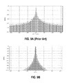
- FIG. 9A is a waveform illustrating a spectral leakage, as known in the prior art.
- FIG. 9B is a waveform illustrating a spectral leakage according to an embodiment of the present invention.
- FIG. 10 is a diagram illustrating the extracted pilot tones at the output of the pilot extractor block according to an embodiment of the present invention.
- FIG. 11 is a channel impulse response signal at the output of the noise removal block according to an embodiment of the present invention.
- FIG. 12 is a channel frequency response signal at the output of the second discrete Fourier Transform block according to an embodiment of the present invention.
- FIG. 13 is a diagram showing the error of the estimated channel response against a channel response under ideal channel conditions according to an embodiment of the present invention.
- the present invention provides a method and apparatus for estimating a channel frequency response in pilot tones assisted OFDM systems.
- FIG. 1 is a high-level block diagram of an OFDM receiver 100 .
- a radio frequency (RF) front-end module 110 includes an input coupled to an antenna 102 and configured to down-convert an RF signal to a baseband signal 112 .
- the RF signal may be a television broadcast signal, a cellular radio signal or a wireless or wired data signal.
- the receiver can be a direct conversion or a dual conversion receiver using a two stages frequency translation to down-convert the received RF signal to an intermediate frequency (IF) signal, a near-zero IF signal, or a zero-IF baseband signal.
- IF intermediate frequency
- the term baseband signal refers to baseband signals as well as to signals that are substantially baseband signals.
- a signal is substantially baseband signal if the frequency conversion process to downconvert a signal is imperfect, for example, due to LO errors or LO differences at the transmitter and the receiver.
- the term baseband signal can also be used to refer to a low IF signal or an IF signal that has a frequency substantially lower than the RF signal.
- the baseband signal can be an intermediate frequency (IF) signal, a near-zero IF signal, or a zero-IF signal.
- the baseband signal includes at least one OFDM symbol having a plurality of data carriers and pilot tones.
- a cyclic prefix or guard interval which is a copy of a portion of an OFDM symbol and is added at the transmitter to protect against delay spreads (time dispersions) caused by multipath, is stripped off of the OFDM symbol.
- the scattered pilot tones are spaced apart in equal frequency amount within the OFDM symbol.
- the RF front-end module includes an output that is coupled to an analog-digital converter (ADC) module 120 that converts the baseband signal to a digital baseband signal 122 .
- ADC analog-digital converter
- the digital baseband signal is then processed in a digital signal processing (DSP) module 130 that may perform time-domain to frequency-domain conversion and vice versa and other windowing functions.
- DSP digital signal processing
- the DSP module 130 may also performs channel estimation and signal demodulation to retrieve the originally transmitted data.
- Receiver 100 further include a memory module 140 that is coupled to the DSP module and contains program instructions that, when executed, cause the DSP module to perform a variety of functions to accurately estimate a channel response.
- FIG. 7 is a simplified flowchart of steps of a computer-implemented method 700 for estimating a channel in a pilot assisted OFDM system, according to an embodiment of the present invention.
- the method 700 can be performed, for example, by the receiver 100 shown in FIG. 1 .
- the method 700 begins at 710 where an RF signal is received.
- the received RF signal is converted to a baseband signal at 715 .
- the baseband signal is converted to a digital baseband signal at 720 .
- the digital baseband signal is converted to a frequency-domain signal at 725 .
- the frequency-domain conversion may be performed using a discrete Fourier Transform operation or a Fast Fourier Transform operation.
- At least a subset of pilot tones is extracted from the OFDM symbol at 730 .
- the subset can include a portion of the pilot tones or the entire pilot pilots containing in the OFDM symbol.
- the extracted pilot tones (the subset or the entire pilot tones) in the OFDM symbol is then filtered with a first Window function at 735 .
- the filtered pilot tones are then converted to a channel impulse response in the time domain at 740 .
- the channel impulse response can be obtained using an inverse discrete Fourier transform or an inverse fast Fourier transform operation that can be performed by the digital signal processing module as shown in FIG. 1 .
- Noises from the channel impulse response signal are removed at 745 .
- the noise free channel impulse response signal is then transformed back to a channel frequency response signal in the frequency domain at 750 .
- the channel frequency response signal is then filtered by a second Window function at 755 .
- the method then proceeds to block 760 and further processes the filtered channel frequency response signal.
- the receiver 100 of FIG. 1 does not need to receive all scattered pilot tones in the OFDM symbol. If some scattered pilot tones cannot be received due to a frequency-selective channel, the receiver can reconstruct the missing pilot tones by replacing them using the received adjacent pilot tones or by interpolating the received adjacent pilot tones.
- the receiver filters the extracted pilot tones with a first window function to reduce the signal loss and noise in the channel estimate while suppressing spectral leakage.
- a window function is a mathematical function that has substantially zero value outside a predetermined interval. Within the predetermined interval, the window function can have many values (or shapes). Most known window functions are rectangular window, triangular window, bell-shaped window.
- the first window function can be a Hann (aka. Hanning) Window function, a Hamming Window function, or the like.
- the window function is a Hann Window function, which is also known as a Hanning Window function.
- a Window function assigns a weight to the extracted pilot tones by multiplying them with a set of discrete value.
- the receiver transforms the thus weighted pilot tones into a time-domain signal, which is representative of a channel impulse response having a main or the largest tap and multiple adjacent taps at 740 .
- the channel taps following the main tap are the post-cursor taps while the channel taps preceding the main tap are the precursor taps.
- the receiver removes precursor and post-cursor taps that have energy or magnitude levels below a predetermined energy or magnitude level.
- the taps can be removed at 745 using a noise limiter that may comprise a window separator centered around the main tap and having a width to pass through taps that are located around the main tap.
- the noise limiter may comprise a threshold separator that passes through only taps having an energy or magnitude level greater than a predetermined energy or magnitude threshold.
- a noise remover may comprise a combination of a window separator and a threshold separator, wherein the combined window and threshold separator forms a channel estimation window that only passes through the main tap and adjacent taps having sufficient energy or magnitude levels. The main tap and the adjacent taps with sufficient energy levels are then transformed into a frequency-domain signal that is an estimated channel frequency response signal at 750 .
- the energy level of each tap can be calculated by squaring absolute values of a channel response of each tap.
- the receiver further filters the estimated channel frequency response signal with a second window function to generate an accurate channel frequency response signal at 755 .
- the second window function may be an inverse of the first window function so that the product of the first and second window functions is substantially equal to unity.
- the thus filtered channel frequency response signal is further processed in the DSP module 130 , as shown in FIG. 1 .
- the receiver can be produced on a single IC. Such an implementation allows the various elements to be better matched that is generally possible using discrete elements or multiple ICs.
- the steps of the method 700 may be embodied in hardware, in a software module executed by a processor, or in a combination of the two. The various steps may be performed in the order shown, or may be omitted or one or more process steps may be added to the method. An additional step, block, or algorithm may be added in the beginning, end, or intervening elements of the method.
- FIG. 8 is a simplified block diagram illustrating the processing stages of a system 800 for estimating a channel frequency response, according to an embodiment of the present invention.
- System 800 is shown as including a transform block 810 that receives digital baseband signal A in the time domain and transforms it to a digital frequency-domain signal B by performing a discrete Fourier Transform or a Fast Fourier Transform operation.
- the frequency-domain signal B includes at least an OFDM symbol having a plurality of data carriers and a plurality of scattered pilot tones.
- the receiver further proceeds to pilot tones extractor block 820 and extracts the scattered pilot tones from the OFDM symbol.
- the receiver does not need to receive all scattered pilot tones in the OFDM symbol.
- the receiver can reconstruct the missing pilot tones by replacing them using the received adjacent pilot tones or by interpolating the received adjacent pilot tones.
- the pilot tones may be dispersed among the data carriers at a regular or variable frequency interval.
- the pilot tone extractor block 820 extracts a subset of pilot tones C from the received and/or reconstructed pilot tones.
- the subset of pilot tones C may include a portion of or the entire number of pilot tones in the OFDM symbol.
- the extracted pilot tones C are then multiplied (filtered) by a first window function (filter) in a window function logic block 830 to reduce the spectral leakage of the pilot tones.
- the window function can be a Hamming Window, a Hann (also known as Hanning) Window, and the like.
- ⁇ N and w ( n ) 0 otherwise (1)
- FIG. 9A illustrates the waveform of the spectral leakage as known to the prior art while FIG. 9B illustrates the waveform of the spectral leakage according to an embodiment of the present invention.
- the signal loss is significantly reduced when the extracted pilot tones are filtered (multiplied) with a Hann Window function.
- the Hann Window function enables the spectral energy of the pilot tones to concentrate around the main tap (at the “0” bin) so that a subsequent noise removal block 850 only removes noises so that the adjacent precursor and post-cursor taps that are part of a channel impulse response are not removed.
- the frequency bins of the prior art shown in FIG. 9A extend far beyond the main bin.
- FIG. 10 illustrates the spectrum density of the extracted pilot tones D after being filtered by a Hann window function 830 .
- the x-axis is shown in frequency (Hz) and the y-axis is given for a normalized power spectrum density in dB.
- Hz frequency
- dB normalized power spectrum density
- FIG. 11 is a waveform illustrating the then obtained channel impulse response F with reduced noises.
- the x-axis is shown in delay time in ns and the y-axis is given for a normalized power spectral density in dB.
- the channel impulse response signal F comprises a main tap, other precursor and post-cursor taps are insignificant or non-existent.
- precursor and post-cursor taps are present in the prior art (shown in FIG. 4 ) so that a noise removal using window and threshold separator may remove not only noises, but also other taps that contain useful information about the channel impulse response signal.
- the inverse discrete Fourier Transform block 840 receives the filtered pilot tones D and generates a time-domain signal E with N elements corresponding to the N sample values of the window function 830 in Equation (1). It is noted that the inverse discrete Fourier Transform can be realized as a Fast Fourier Transform algorithm in an embodiment.
- noise removal block 850 may include a band-pass filter that passes the main tap and its adjacent taps (precursor and post-cursor taps), an absolute value converter that converts the passed taps into an amplitude having a positive value, and a threshold comparator that identifies values that equal or exceed a predetermined level. Thus, taps having amplitude or power level lower than the predetermined level will be filtered out.
- the channel impulse response signal F after the noise removal block 850 is noise free.
- a discrete Fourier Transform block 860 transforms the channel impulse response signal F into a frequency-domain signal G, which is then multiplied (filtered) with a second window function provided in logic block 870 . It is noted that the discrete Fourier Transform and inverse Fourier Transform blocks can be implemented in hardware, in a software module executed by a digital signal processor, as shown in FIG. 1 .
- FIG. 12 is a waveform illustrating the then obtained channel frequency response signal H at the output of the second window function 870 .
- the x-axis is given in frequency (Hz) and the y-axis is given for a normalized power spectral density in dB.
- the spectral density of the estimated channel frequency response has 0 db and is flat at the center frequency (around 1100 Hz in this example embodiment) comparing to the waveform obtained using conventional channel estimation techniques (see FIG. 5 ).
- FIG. 13 is a waveform diagram illustrating the error of the estimated channel frequency response against a 0 dB AWGN channel (ideal channel conditions). Comparing with that shown in FIG. 6 of the prior art, the spectral density error is much lower (e.g., 30 dB vs. 100 dB of the prior art).
- the substantial reduction in the spectral density error of the present invention is due to the addition of the first and second window functions shown as logic blocks 830 , 870 in system 800 . It is appreciated that logic blocks can be implemented in hardware, software, or a combination thereof. Although the blocks are shown as discrete functions in the Figures, they can be combined and/or shared in some embodiments. For example, a same hardware circuit and a software module can be used to perform functions or operations of blocks 810 , 840 , and 860 .
- time-domain and frequency-domain transformations, the window function, pilot tone extraction, noise removal functions described above as individual steps in FIG. 7 or as logic blocks in FIG. 8 can be performed by a general-purpose or a application-specific digital signal processor shown as the DSP block 130 coupled with a memory block 140 in FIG. 1 .
- Suitable memory modules may include hard-disk drive, flash memory, read-only-memory (ROM), static and/or dynamic RAM, and the like.
- the computer executable instructions may be written in a suitable computer language or combination of several languages.
Landscapes
- Engineering & Computer Science (AREA)
- Power Engineering (AREA)
- Computer Networks & Wireless Communication (AREA)
- Signal Processing (AREA)
- Noise Elimination (AREA)
Abstract
Description
w(n)=(1−cos(2πn/N−1)) if |n|<N and w(n)=0 otherwise (1)
Claims (21)
Priority Applications (1)
| Application Number | Priority Date | Filing Date | Title |
|---|---|---|---|
| US13/291,968 US8995589B1 (en) | 2010-11-17 | 2011-11-08 | Channel estimation in a pilot assisted OFDM system |
Applications Claiming Priority (2)
| Application Number | Priority Date | Filing Date | Title |
|---|---|---|---|
| US41481110P | 2010-11-17 | 2010-11-17 | |
| US13/291,968 US8995589B1 (en) | 2010-11-17 | 2011-11-08 | Channel estimation in a pilot assisted OFDM system |
Publications (1)
| Publication Number | Publication Date |
|---|---|
| US8995589B1 true US8995589B1 (en) | 2015-03-31 |
Family
ID=52707916
Family Applications (1)
| Application Number | Title | Priority Date | Filing Date |
|---|---|---|---|
| US13/291,968 Active 2033-04-10 US8995589B1 (en) | 2010-11-17 | 2011-11-08 | Channel estimation in a pilot assisted OFDM system |
Country Status (1)
| Country | Link |
|---|---|
| US (1) | US8995589B1 (en) |
Cited By (4)
| Publication number | Priority date | Publication date | Assignee | Title |
|---|---|---|---|---|
| US20160149734A1 (en) * | 2014-11-20 | 2016-05-26 | Samsung Electronics Co., Ltd. | Apparatus and method for switching between receivers in communication system |
| US20160269208A1 (en) * | 2015-03-11 | 2016-09-15 | Nxp B.V. | Module for a Radio Receiver |
| US9596102B2 (en) * | 2014-09-16 | 2017-03-14 | Samsung Electronics Co., Ltd. | Computing system with channel estimation mechanism and method of operation thereof |
| US20180212729A1 (en) * | 2015-09-25 | 2018-07-26 | Huawei Technologies Co.,Ltd. | Communication Protocol for Low Energy Communication links |
Citations (23)
| Publication number | Priority date | Publication date | Assignee | Title |
|---|---|---|---|---|
| US20030179048A1 (en) * | 2002-03-25 | 2003-09-25 | Arild Kolsrud | Amplifier bias system and method |
| US20040178853A1 (en) * | 2003-03-11 | 2004-09-16 | Barak Ilan Saul | Rf power amplifier with low intermodulation distortion and reduced memory effect |
| US20050276364A1 (en) * | 2004-06-14 | 2005-12-15 | Black Peter J | CDMA pilot assisted channel estimation |
| US20060114075A1 (en) * | 2002-09-26 | 2006-06-01 | Zoran Janosevic | Transmitter and a method of calibrating power in signals output from a transmitter |
| US20080084817A1 (en) * | 2006-10-10 | 2008-04-10 | James Edward Beckman | Channel estimation for multi-carrier communication |
| US20080101483A1 (en) * | 2006-10-31 | 2008-05-01 | Freescale Semiconductor, Inc. | System and method for reducing edge effect |
| US20080101490A1 (en) * | 2006-09-12 | 2008-05-01 | Sony Corporation | OFDM receiver and OFDM signal receiving method |
| US20080130771A1 (en) * | 2006-11-28 | 2008-06-05 | Stefan Fechtel | Channel estimation for ofdm systems |
| US20090110044A1 (en) * | 2007-10-26 | 2009-04-30 | National Chiao Tung University | Method and Apparatus for Deciding a Channel Impulse Response |
| US20090141841A1 (en) * | 2006-07-25 | 2009-06-04 | Fujitsu Limited | Interference noise estimation method, reception processing method, interference noise estimation apparatus, and receiver, in multicarrier communications system |
| US20090252112A1 (en) * | 2006-12-22 | 2009-10-08 | Fujitsu Limited | Radio communication method and a base station and user terminal thereof |
| US20090323666A1 (en) * | 2005-03-29 | 2009-12-31 | Qualcomm Incorporated | Method and apparatus for data and pilot structures supporting equalization |
| US20100054371A1 (en) * | 2004-09-17 | 2010-03-04 | Qualcomm Incorporated | Noise Variance Estimation In Wireless Communications For Diversity Combining and Log Likelihood Scaling |
| US20100067627A1 (en) * | 2008-09-16 | 2010-03-18 | Bo Lincoln | Maximum A Posteriori Interference Estimation in a Wireless Communication System |
| US20100142659A1 (en) * | 2007-03-30 | 2010-06-10 | Zoran Corporation | System and method for fft window timing synchronization for an orthogonal frequency-division multiplexed data stream |
| US20100177251A1 (en) * | 2008-04-11 | 2010-07-15 | Tomohiro Kimura | Receiver, integrated circuit, digital television receiver, reception method, and reception program |
| US20100223522A1 (en) * | 2009-02-27 | 2010-09-02 | Research In Motion Limited | State dependent advanced receiver processing in a wireless mobile device |
| US20100310016A1 (en) * | 2009-06-03 | 2010-12-09 | Sony Corporation | Receiver and method |
| US20110142118A1 (en) * | 2008-08-28 | 2011-06-16 | Jae-Hyun Seo | Apparatus and method for equalizing channel based on channel estimation |
| US20110274220A1 (en) * | 2010-05-10 | 2011-11-10 | Telefonaktiebolaget L M Ericsson (Publ) | Reduced Complexity Timing Estimation for Locating the Position of a Mobile Terminal |
| US20120063529A1 (en) * | 2009-05-11 | 2012-03-15 | Sungkyunkwan University Foundation For Corporate Collaboration | Inter-cell interference mitigation method using spatial covariance matrix estimation method for inter-cell interference mitigation of mimo antenna ofdm system |
| US20120087428A1 (en) * | 2009-06-29 | 2012-04-12 | Freescale Semiconductor, Inc. | Integrated circuit with channel estimation module and method therefor |
| US8275053B2 (en) * | 2006-12-08 | 2012-09-25 | Samsung Electronics Co., Ltd. | Apparatus and method of estimating channel based on channel delay spread in mobile communication system |
-
2011
- 2011-11-08 US US13/291,968 patent/US8995589B1/en active Active
Patent Citations (24)
| Publication number | Priority date | Publication date | Assignee | Title |
|---|---|---|---|---|
| US7064613B2 (en) * | 2002-03-25 | 2006-06-20 | Lucent Technologies Inc. | Amplifier bias system and method |
| US20030179048A1 (en) * | 2002-03-25 | 2003-09-25 | Arild Kolsrud | Amplifier bias system and method |
| US20060114075A1 (en) * | 2002-09-26 | 2006-06-01 | Zoran Janosevic | Transmitter and a method of calibrating power in signals output from a transmitter |
| US20040178853A1 (en) * | 2003-03-11 | 2004-09-16 | Barak Ilan Saul | Rf power amplifier with low intermodulation distortion and reduced memory effect |
| US20050276364A1 (en) * | 2004-06-14 | 2005-12-15 | Black Peter J | CDMA pilot assisted channel estimation |
| US20100054371A1 (en) * | 2004-09-17 | 2010-03-04 | Qualcomm Incorporated | Noise Variance Estimation In Wireless Communications For Diversity Combining and Log Likelihood Scaling |
| US20090323666A1 (en) * | 2005-03-29 | 2009-12-31 | Qualcomm Incorporated | Method and apparatus for data and pilot structures supporting equalization |
| US20090141841A1 (en) * | 2006-07-25 | 2009-06-04 | Fujitsu Limited | Interference noise estimation method, reception processing method, interference noise estimation apparatus, and receiver, in multicarrier communications system |
| US20080101490A1 (en) * | 2006-09-12 | 2008-05-01 | Sony Corporation | OFDM receiver and OFDM signal receiving method |
| US20080084817A1 (en) * | 2006-10-10 | 2008-04-10 | James Edward Beckman | Channel estimation for multi-carrier communication |
| US20080101483A1 (en) * | 2006-10-31 | 2008-05-01 | Freescale Semiconductor, Inc. | System and method for reducing edge effect |
| US20080130771A1 (en) * | 2006-11-28 | 2008-06-05 | Stefan Fechtel | Channel estimation for ofdm systems |
| US8275053B2 (en) * | 2006-12-08 | 2012-09-25 | Samsung Electronics Co., Ltd. | Apparatus and method of estimating channel based on channel delay spread in mobile communication system |
| US20090252112A1 (en) * | 2006-12-22 | 2009-10-08 | Fujitsu Limited | Radio communication method and a base station and user terminal thereof |
| US20100142659A1 (en) * | 2007-03-30 | 2010-06-10 | Zoran Corporation | System and method for fft window timing synchronization for an orthogonal frequency-division multiplexed data stream |
| US20090110044A1 (en) * | 2007-10-26 | 2009-04-30 | National Chiao Tung University | Method and Apparatus for Deciding a Channel Impulse Response |
| US20100177251A1 (en) * | 2008-04-11 | 2010-07-15 | Tomohiro Kimura | Receiver, integrated circuit, digital television receiver, reception method, and reception program |
| US20110142118A1 (en) * | 2008-08-28 | 2011-06-16 | Jae-Hyun Seo | Apparatus and method for equalizing channel based on channel estimation |
| US20100067627A1 (en) * | 2008-09-16 | 2010-03-18 | Bo Lincoln | Maximum A Posteriori Interference Estimation in a Wireless Communication System |
| US20100223522A1 (en) * | 2009-02-27 | 2010-09-02 | Research In Motion Limited | State dependent advanced receiver processing in a wireless mobile device |
| US20120063529A1 (en) * | 2009-05-11 | 2012-03-15 | Sungkyunkwan University Foundation For Corporate Collaboration | Inter-cell interference mitigation method using spatial covariance matrix estimation method for inter-cell interference mitigation of mimo antenna ofdm system |
| US20100310016A1 (en) * | 2009-06-03 | 2010-12-09 | Sony Corporation | Receiver and method |
| US20120087428A1 (en) * | 2009-06-29 | 2012-04-12 | Freescale Semiconductor, Inc. | Integrated circuit with channel estimation module and method therefor |
| US20110274220A1 (en) * | 2010-05-10 | 2011-11-10 | Telefonaktiebolaget L M Ericsson (Publ) | Reduced Complexity Timing Estimation for Locating the Position of a Mobile Terminal |
Cited By (7)
| Publication number | Priority date | Publication date | Assignee | Title |
|---|---|---|---|---|
| US9596102B2 (en) * | 2014-09-16 | 2017-03-14 | Samsung Electronics Co., Ltd. | Computing system with channel estimation mechanism and method of operation thereof |
| US20160149734A1 (en) * | 2014-11-20 | 2016-05-26 | Samsung Electronics Co., Ltd. | Apparatus and method for switching between receivers in communication system |
| US9654318B2 (en) * | 2014-11-20 | 2017-05-16 | Samsung Electronics Co., Ltd. | Apparatus and method for switching between receivers in communication system |
| US20160269208A1 (en) * | 2015-03-11 | 2016-09-15 | Nxp B.V. | Module for a Radio Receiver |
| US9893924B2 (en) * | 2015-03-11 | 2018-02-13 | Nxp B.V. | Module for a radio receiver |
| US20180212729A1 (en) * | 2015-09-25 | 2018-07-26 | Huawei Technologies Co.,Ltd. | Communication Protocol for Low Energy Communication links |
| US10237036B2 (en) * | 2015-09-25 | 2019-03-19 | Huawei Technologies Co., Ltd. | Reporting downlink connection failure using low bandwidth uplink pilot signal |
Similar Documents
| Publication | Publication Date | Title |
|---|---|---|
| JP4938679B2 (en) | Inter-carrier interference canceling apparatus and receiving apparatus using the same | |
| US7852958B2 (en) | Receiving apparatus, integrated circuit and receiving method | |
| US9374291B2 (en) | Downstream OFDM signal egress detection | |
| US8837616B2 (en) | Equalization of a distributed pilot OFDM signal | |
| JP4352082B2 (en) | Frequency synchronization circuit, method, program, and receiver using the same | |
| US8995589B1 (en) | Channel estimation in a pilot assisted OFDM system | |
| JP2007074669A (en) | Receiving apparatus and receiving method | |
| US20100074346A1 (en) | Channel estimation in ofdm receivers | |
| EP1520349B1 (en) | Method and device for wavelet denoising | |
| JP2002026865A (en) | Demodulating apparatus and demodulation method | |
| WO2013080578A1 (en) | Receiver and method | |
| JP2013106112A (en) | Interference wave detection circuit, receiver, and interference wave detection method | |
| JP2010087744A (en) | Reception device, reception method, and program | |
| JP5237860B2 (en) | Digital broadcast receiver | |
| JP3793534B2 (en) | OFDM receiving apparatus and OFDM signal receiving method | |
| EP1684479B1 (en) | Method and system for impulse noise rejection in an OFDM system | |
| JP3757144B2 (en) | OFDM receiving apparatus and OFDM signal receiving method | |
| JP2008271298A (en) | Demodulation apparatus, receiver, demodulation method and demodulation program | |
| EP3890193B1 (en) | Processing amplitude modulation signals with noise estimation | |
| WO2011132299A1 (en) | Reception device and reception method | |
| JP4930262B2 (en) | OFDM receiving apparatus and OFDM receiving method | |
| JP4704229B2 (en) | Receiver | |
| WO2012114769A1 (en) | Channel estimation device and channel estimation method | |
| EP2624514A2 (en) | Removal of a band-limited distributed pilot from an OFDM signal | |
| Islam et al. | Zero padded suffix aided subspace-based narrowband interference detected adaptive channel estimation for MB-OFDM UWB systems |
Legal Events
| Date | Code | Title | Description |
|---|---|---|---|
| AS | Assignment |
Owner name: MAXLINEAR, INC., CALIFORNIA Free format text: ASSIGNMENT OF ASSIGNORS INTEREST;ASSIGNOR:QIU, JAMES;REEL/FRAME:027195/0202 Effective date: 20111108 |
|
| STCF | Information on status: patent grant |
Free format text: PATENTED CASE |
|
| FEPP | Fee payment procedure |
Free format text: PAT HOLDER NO LONGER CLAIMS SMALL ENTITY STATUS, ENTITY STATUS SET TO UNDISCOUNTED (ORIGINAL EVENT CODE: STOL); ENTITY STATUS OF PATENT OWNER: LARGE ENTITY |
|
| AS | Assignment |
Owner name: JPMORGAN CHASE BANK, N.A., AS COLLATERAL AGENT, IL Free format text: SECURITY AGREEMENT;ASSIGNORS:MAXLINEAR, INC.;ENTROPIC COMMUNICATIONS, LLC (F/K/A ENTROPIC COMMUNICATIONS, INC.);EXAR CORPORATION;REEL/FRAME:042453/0001 Effective date: 20170512 Owner name: JPMORGAN CHASE BANK, N.A., AS COLLATERAL AGENT, ILLINOIS Free format text: SECURITY AGREEMENT;ASSIGNORS:MAXLINEAR, INC.;ENTROPIC COMMUNICATIONS, LLC (F/K/A ENTROPIC COMMUNICATIONS, INC.);EXAR CORPORATION;REEL/FRAME:042453/0001 Effective date: 20170512 |
|
| MAFP | Maintenance fee payment |
Free format text: PAYMENT OF MAINTENANCE FEE, 4TH YEAR, LARGE ENTITY (ORIGINAL EVENT CODE: M1551); ENTITY STATUS OF PATENT OWNER: LARGE ENTITY Year of fee payment: 4 |
|
| AS | Assignment |
Owner name: MUFG UNION BANK, N.A., CALIFORNIA Free format text: SUCCESSION OF AGENCY (REEL 042453 / FRAME 0001);ASSIGNOR:JPMORGAN CHASE BANK, N.A.;REEL/FRAME:053115/0842 Effective date: 20200701 |
|
| AS | Assignment |
Owner name: MAXLINEAR, INC., CALIFORNIA Free format text: RELEASE BY SECURED PARTY;ASSIGNOR:MUFG UNION BANK, N.A.;REEL/FRAME:056656/0204 Effective date: 20210623 Owner name: EXAR CORPORATION, CALIFORNIA Free format text: RELEASE BY SECURED PARTY;ASSIGNOR:MUFG UNION BANK, N.A.;REEL/FRAME:056656/0204 Effective date: 20210623 Owner name: MAXLINEAR COMMUNICATIONS LLC, CALIFORNIA Free format text: RELEASE BY SECURED PARTY;ASSIGNOR:MUFG UNION BANK, N.A.;REEL/FRAME:056656/0204 Effective date: 20210623 |
|
| AS | Assignment |
Owner name: WELLS FARGO BANK, NATIONAL ASSOCIATION, COLORADO Free format text: SECURITY AGREEMENT;ASSIGNORS:MAXLINEAR, INC.;MAXLINEAR COMMUNICATIONS, LLC;EXAR CORPORATION;REEL/FRAME:056816/0089 Effective date: 20210708 |
|
| MAFP | Maintenance fee payment |
Free format text: PAYMENT OF MAINTENANCE FEE, 8TH YEAR, LARGE ENTITY (ORIGINAL EVENT CODE: M1552); ENTITY STATUS OF PATENT OWNER: LARGE ENTITY Year of fee payment: 8 |