US8991741B2 - Convertiplane - Google Patents
Convertiplane Download PDFInfo
- Publication number
- US8991741B2 US8991741B2 US13/560,142 US201213560142A US8991741B2 US 8991741 B2 US8991741 B2 US 8991741B2 US 201213560142 A US201213560142 A US 201213560142A US 8991741 B2 US8991741 B2 US 8991741B2
- Authority
- US
- United States
- Prior art keywords
- convertiplane
- relative
- semi
- wings
- rotors
- Prior art date
- Legal status (The legal status is an assumption and is not a legal conclusion. Google has not performed a legal analysis and makes no representation as to the accuracy of the status listed.)
- Active, expires
Links
- 230000005484 gravity Effects 0.000 claims description 4
- 230000007704 transition Effects 0.000 description 4
- 239000013598 vector Substances 0.000 description 4
- RZVHIXYEVGDQDX-UHFFFAOYSA-N 9,10-anthraquinone Chemical compound C1=CC=C2C(=O)C3=CC=CC=C3C(=O)C2=C1 RZVHIXYEVGDQDX-UHFFFAOYSA-N 0.000 description 3
- 238000005452 bending Methods 0.000 description 3
- 238000002485 combustion reaction Methods 0.000 description 3
- 230000000694 effects Effects 0.000 description 3
- 230000004907 flux Effects 0.000 description 3
- 230000033001 locomotion Effects 0.000 description 3
- 125000004122 cyclic group Chemical group 0.000 description 2
- 230000007423 decrease Effects 0.000 description 2
- 230000003247 decreasing effect Effects 0.000 description 2
- 241000272517 Anseriformes Species 0.000 description 1
- 230000000712 assembly Effects 0.000 description 1
- 238000000429 assembly Methods 0.000 description 1
- 230000005540 biological transmission Effects 0.000 description 1
- 230000015572 biosynthetic process Effects 0.000 description 1
- 238000005755 formation reaction Methods 0.000 description 1
- 239000000446 fuel Substances 0.000 description 1
- 229910001416 lithium ion Inorganic materials 0.000 description 1
- 238000004519 manufacturing process Methods 0.000 description 1
- 230000002093 peripheral effect Effects 0.000 description 1
- 230000000007 visual effect Effects 0.000 description 1
Images


Classifications
-
- B—PERFORMING OPERATIONS; TRANSPORTING
- B64—AIRCRAFT; AVIATION; COSMONAUTICS
- B64C—AEROPLANES; HELICOPTERS
- B64C27/00—Rotorcraft; Rotors peculiar thereto
- B64C27/22—Compound rotorcraft, i.e. aircraft using in flight the features of both aeroplane and rotorcraft
-
- B—PERFORMING OPERATIONS; TRANSPORTING
- B64—AIRCRAFT; AVIATION; COSMONAUTICS
- B64C—AEROPLANES; HELICOPTERS
- B64C11/00—Propellers, e.g. of ducted type; Features common to propellers and rotors for rotorcraft
- B64C11/001—Shrouded propellers
-
- B—PERFORMING OPERATIONS; TRANSPORTING
- B64—AIRCRAFT; AVIATION; COSMONAUTICS
- B64C—AEROPLANES; HELICOPTERS
- B64C27/00—Rotorcraft; Rotors peculiar thereto
- B64C27/32—Rotors
- B64C27/46—Blades
- B64C27/467—Aerodynamic features
-
- B—PERFORMING OPERATIONS; TRANSPORTING
- B64—AIRCRAFT; AVIATION; COSMONAUTICS
- B64C—AEROPLANES; HELICOPTERS
- B64C29/00—Aircraft capable of landing or taking-off vertically, e.g. vertical take-off and landing [VTOL] aircraft
- B64C29/0008—Aircraft capable of landing or taking-off vertically, e.g. vertical take-off and landing [VTOL] aircraft having its flight directional axis horizontal when grounded
- B64C29/0016—Aircraft capable of landing or taking-off vertically, e.g. vertical take-off and landing [VTOL] aircraft having its flight directional axis horizontal when grounded the lift during taking-off being created by free or ducted propellers or by blowers
- B64C29/0033—Aircraft capable of landing or taking-off vertically, e.g. vertical take-off and landing [VTOL] aircraft having its flight directional axis horizontal when grounded the lift during taking-off being created by free or ducted propellers or by blowers the propellers being tiltable relative to the fuselage
-
- B—PERFORMING OPERATIONS; TRANSPORTING
- B64—AIRCRAFT; AVIATION; COSMONAUTICS
- B64C—AEROPLANES; HELICOPTERS
- B64C3/00—Wings
- B64C3/38—Adjustment of complete wings or parts thereof
- B64C3/54—Varying in area
-
- B—PERFORMING OPERATIONS; TRANSPORTING
- B64—AIRCRAFT; AVIATION; COSMONAUTICS
- B64C—AEROPLANES; HELICOPTERS
- B64C3/00—Wings
- B64C3/38—Adjustment of complete wings or parts thereof
- B64C3/56—Folding or collapsing to reduce overall dimensions of aircraft
-
- B—PERFORMING OPERATIONS; TRANSPORTING
- B64—AIRCRAFT; AVIATION; COSMONAUTICS
- B64C—AEROPLANES; HELICOPTERS
- B64C37/00—Convertible aircraft
-
- Y—GENERAL TAGGING OF NEW TECHNOLOGICAL DEVELOPMENTS; GENERAL TAGGING OF CROSS-SECTIONAL TECHNOLOGIES SPANNING OVER SEVERAL SECTIONS OF THE IPC; TECHNICAL SUBJECTS COVERED BY FORMER USPC CROSS-REFERENCE ART COLLECTIONS [XRACs] AND DIGESTS
- Y02—TECHNOLOGIES OR APPLICATIONS FOR MITIGATION OR ADAPTATION AGAINST CLIMATE CHANGE
- Y02T—CLIMATE CHANGE MITIGATION TECHNOLOGIES RELATED TO TRANSPORTATION
- Y02T50/00—Aeronautics or air transport
- Y02T50/10—Drag reduction
-
- Y02T50/145—
Definitions
- the present invention relates to a convertiplane, i.e. a hybrid aircraft with adjustable rotors, capable of selectively assuming an “aeroplane” configuration, in which the rotors are positioned with their axes substantially parallel to the longitudinal axis of the aircraft, and a “helicopter” configuration, in which the rotors are positioned with their axes substantially vertical and crosswise to the longitudinal axis of the aircraft, so as to combine the advantages of a fixed-wing turboprop aircraft and a helicopter.
- a convertiplane i.e. a hybrid aircraft with adjustable rotors, capable of selectively assuming an “aeroplane” configuration, in which the rotors are positioned with their axes substantially parallel to the longitudinal axis of the aircraft, and a “helicopter” configuration, in which the rotors are positioned with their axes substantially vertical and crosswise to the longitudinal axis of the aircraft, so as to combine the advantages of a fixed-wing turboprop aircraft
- the ability to adjust its rotors as described enables a convertiplane to take off and land like a helicopter, i.e. with no need for a runway and along extremely steep trajectories, to minimize ground noise and, for example, even take off and land in urban areas; and to fly like an aeroplane capable of reaching and maintaining a cruising speed of roughly 500 km/h, or at any rate higher than the roughly 300 km/h cruising speed of a helicopter, and a typical cruising height of 7500 meters, which is roughly twice that of a helicopter, and enables it to fly above most cloud formations and atmospheric disturbance.
- a convertiplane has the advantages of almost twice the cruising speed; substantially twice the flying distance and time for a given payload and fuel supply, thus making it cheaper to operate; and over twice the cruising height, thus making it insensitive to weather conditions (clouds, turbulence) over most of the flight.
- a convertiplane has the advantages of being able to hover, and to take off and land in confined spaces, even in urban areas.
- substantially two convertiplane configurations are known: “Tilt Rotor”, in which the semi-wing remain substantially fixed, and only the motor-rotor assemblies rotate relative to the semi-wings; and “Tilt Wing”, in which the rotor attitude is adjusted by rotating the semi-wing and rotors system assembly as a whole.
- Tilt Rotor configurations are shown in U.S. Pat. No. 6,220,545 or in US-A-2009/0256026.
- An example of “Tilt Wing” configuration is shown in EP-A-1057724.
- Known tilt-rotor convertiplanes substantially comprise a fuselage, a pair of semi-wings projecting on opposite lateral sides of the fuselage, and a pair of nacelles which rotate relative to respective semi-wings.
- Each nacelle houses a relative motor-rotor assembly, which, therefore, rotates together with the nacelle relative to the corresponding semi-wing.
- the semi-wings are straight and each nacelle is arranged substantially at the tip of the relative semi-wings.
- the position of nacelles reduces the lifting surfaces of the semi-wings.
- the wind shielding effect is caused by the fact that the downwash of rotor partially impinges on the semi-wings, thus reducing the available lift.
- US-A-2011/003135 discloses a convertiplane comprising a fuselage, a front wing and a back wing, and a pair of booms extending between wing and each supporting a rotor.
- Rotors are arranged on lateral sides of fuselage and each rotor tilts in an area defined by the relative side of the fuselage and the front and back wings.
- U.S. Pat. No. 6,434,768 discloses a convertiplane comprising a wing and a pair of counter-rotating rotors which may tilt relative to wing. Counter-rotating rotors are coaxially mounted and, therefore, both rotate and tilt about the same axis.
- FIG. 1 is a perspective view of a convertiplane according to the invention in an airplane mode
- FIG. 2 is a perspective view of the convertiplane of FIG. 1 in a helicopter mode
- FIG. 3 is a perspective view of the convertiplane of FIGS. 1 and 2 in a transition mode between the helicopter and the aeroplane mode;
- FIG. 4 is a top view of the convertiplane of FIGS. 1 to 3 in a first operative configuration
- FIG. 5 is a top view of the convertiplane of FIGS. 1 to 3 in a second operative configuration
- FIGS. 6 and 7 cross sections of first components of FIG. 4 taken along lines VI-VI and VII-VII respectively of FIG. 6 ;
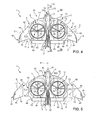
- FIG. 8 is a lateral view of the convertiplane of FIGS. 1 to 3 in the second operative configuration
- FIG. 9 is a perspective view of a further component of the convertiplane of FIGS. 1 to 4 , with parts removed for clarity;
- FIG. 10 is a cross section of the fourth component taken along line X-X of FIG. 9 ;
- FIGS. 11 to 17 are perspective view of respective components of the convertiplane of FIGS. 1 to 4 , with parts removed for clarity.
- Number 1 in FIGS. 1 to 3 indicates as a whole a convertiplane, i.e. a hybrid aircraft capable of being selectively operated in an aeroplane mode ( FIG. 1 ) or in a helicopter mode ( FIG. 2 ).
- Convertiplane 1 substantially comprises:
- fuselage 2 has a forward end 15 a backward end 16 which are opposite to each other, along direction A and define opposite ends of convertiplane 1 .
- Fuselage 2 also comprises ( FIG. 6 ):
- Each rotor 4 substantially comprises:
- Each rotor 4 also comprises a plurality of blades 27 , three in the embodiment shown, which are articulated relative to shaft 6 through the interposition of a hub 28 .
- convertiplane 1 does not need an anti-rotation device.
- the transversal section of fuselage 2 in a plane parallel to direction A and orthogonal to axis C is shaped as airfoil 35 .
- airfoil 35 comprises:
- Topside and bottom side 37 , 38 are, in the embodiment shown both, convex.
- Topside and bottom side 37 , 38 are, in the embodiment shown, symmetrical relative to a rectilinear chord 39 which connects edges 15 , 16 .
- airfoil 35 generates a lift, when convertiplane 1 flies with direction A slightly inclined relative to a horizontal plane, due to the fact that the air current direction is not parallel to chord 39 .
- Convertiplane 1 also comprises:
- Each rotor 4 may also tilt together with its respective axis B relative to respective semi-wing 3 .
- rotor 4 and relative axis B tilt about a respective axis C which is orthogonal to direction A.
- axes B of rotors 4 are substantially orthogonal to direction A, when convertiplane 1 is operated in the helicopter mode ( FIG. 2 ).
- convertiplane 1 is a “so-called” tilt rotor convertiplane.
- Axes B of rotors 4 are substantially parallel to direction A, when convertiplane 1 is operated in the aeroplane mode ( FIG. 1 ).
- convertiplane 1 defines a pair of openings 8 within which rotors 4 may tilt, when convertiplane 1 moves between helicopter and aeroplane mode.
- each semi-wing 3 defines a relative opening 8 .
- Each semi-wing 3 substantially comprises ( FIGS. 4 and 5 ):
- Leading edges 10 converge, on respective opposite sides, towards fuselage 2 , when proceeding from V-shaped tail 7 to end 15 .
- the distance measured parallel to axis C between edges 10 decreases proceeding from V-shaped tail 7 to end 15 .
- Each leading edge 10 comprises ( FIGS. 4 and 5 ):
- Each trailing edge 11 comprises:
- Corresponding stretches 42 , 45 protrude upwardly from a plane defined by direction A and axis C, so as to form relative winglets 19 which are arranged on respective opposite sides of fuselage 2 .
- Each opening 8 is arranged between fuselage 2 and relative winglet 19 parallel to relative axis C and is arranged between stretches 41 , 43 parallel to direction A.
- Each opening 8 extends about an axis D and is, in the embodiment shown, circular.
- each opening 8 has an edge 29 , circular in the embodiment shown,
- axes B are orthogonal to respective axes D, and rotors 4 protrude from opposite, top and bottom, sides of relative openings 8 .
- Axes B are also orthogonal to relative axes C.
- axes B are parallel to respective axes D and rotors 4 are axially contained within relative openings 8 .
- the thickness of rotors 4 parallel to axes D is less than or equal to the thickness of relative openings 8 parallel to axes D.
- the centre of gravity of convertiplane 1 lies on a common direction defined by axes C and is arranged at the same distance from axes D.
- convertiplane 1 when convertediplane 1 is operated as “helicopter mode”, the downward weight vector of convertiplane 1 is balanced by the upward thrust vectors of rotors 4 , without generating any de-stabilizing couple about direction A.
- Each semi-wing 3 comprises ( FIGS. 4 and 5 ):
- convertiplane 1 may be operated:
- body 17 comprises fuselage 2 and V-shaped tail 7 and openings 8 .
- Body 17 is bounded by stretches 41 , stretches 43 , 44 and by a pair of walls 32 which lies on a plane orthogonal to axis C.
- the cross section of body 17 taken a plane orthogonal to axis C comprises a pair of airfoils 60 , 65 ( FIG. 7 ).
- Airfoil 60 is bounded between leading edge 10 and a forward portion 47 of edge 29 along direction A.
- Airfoil 60 comprises a topside 61 and a bottom side 62 which join edges 10 and forward portion 47 .
- Airfoil 60 extends symmetrically about a rectilinear chord 63 which joins edge 11 and forward portion 47 .
- Topside and bottom side 61 , 62 are, in the embodiment shown, both convex.
- Airfoil 65 is bounded between a rearward portion 48 of edge 29 and trailing edge 11 along direction A.
- Airfoil 65 comprises a topside 66 and a bottom side 67 which join rearward portion 48 and trailing edge 11 .
- Airfoil 65 extends symmetrically about a rectilinear chord 68 which joins edge 11 and rearward portion 48 .
- Topside and bottom side 66 , 67 are, in the embodiment shown, both convex.
- airfoils 60 , 65 generate a lift, when convertiplane 1 flies with direction A slightly inclined relative to a horizontal plane, due to the fact that the air current direction is not parallel to chords 63 , 68 .
- Each wing 18 comprises relative winglet 19 and is bounded by relative stretches 42 , 45 on opposite sides.
- Each wing 18 is also bounded by a wall 33 on the opposite side of relative winglet 19 .
- Wall 33 of each wing 18 is detachably connected to a relative wall 32 of body 17 .
- Each wing 18 is, in particular, backward swept to provide roll stability and reducing wing span for obtaining a given amount of lift.
- Convertiplane 1 also comprises pair of elevons 40 which are arranged on respective stretches 45 and on respective sides of V-shaped tail 7 .
- Elevons 40 are hinged to body 17 about an axis H parallel to axis C. In this way, elevons 40 may move upwardly and downwardly relative to body 17 for controlling the pitch and the roll during horizontal flight.
- Each rotor 4 comprises ( FIG. 9 ):
- shroud 20 and spokes 30 rotate integrally with blades 27 of each rotor 4 about relative axis C, when convertiplane 1 moves from helicopter and aeroplane mode and vice versa.
- shroud 20 and spokes 30 are fixed relative to axis B of each rotor 4 .
- each shroud 20 extends about relative axis B and has a thickness about a relative axis E orthogonal to relative axis B ( FIGS. 9 and 10 ).
- Each shroud 20 comprises ( FIG. 10 ):
- the cross section of shroud 20 taken in the plane defined by relative axes E, B is configured as an airfoil 25 .
- topside 23 and bottom side 24 are antisymmetrical relative to a chord 26 which joins leading and trailing edges 21 , 22 .
- topside 23 and bottom side 24 are convex.
- the thickness of airfoil 25 i.e. the distance between topside 23 and bottom side 24 measured orthogonally to chord 26 , at first increases and then decreases, proceeding from leading edge 21 to trailing edge 22 .
- Convertiplane 1 comprises:
- Each actuator 52 comprises, in turn,
- Each actuator 52 also comprises a control unit 51 for controlling the movement of ram 54 parallel to direction A.
- Control units 51 are, in turn, controlled by flight control computer 49 on the basis of a plurality of flight and mission parameters.
- the movement of ram 54 relative to fixed part 53 is caused by an electric motor (not-shown).
- each actuator 52 comprises a bar 59 which extends parallel to relative axis C.
- Bar 59 of each actuator 52 comprises ( FIGS. 11 and 12 ):
- convertiplane 1 comprises a plurality of connecting elements 92 (only one of which is shown in FIG. 12 ) for connecting relative spokes 30 to shroud 20 .
- each connecting element 92 comprises a pair of walls 94 fitted to relative spoke 30 , and a central portion 95 fitted to a peripheral portion of shroud 20 and coupled with end 91 of bar 59 .
- each end 91 and corresponding central portion 95 are coupled by using a splined fitting.
- central portions 95 and ends 91 of bars 59 are partially housed within a cavity defined by shroud 20 ( FIG. 12 ).
- each actuator 52 may tilt relative rotor 4 towards end 15 or towards end 16 .
- each actuator 52 may tilt relative rotor 4 forward or rearwards relative to axis D.
- convertiplane 1 comprises an electrical power storage device 70 ; and two pairs of electric machines 71 .
- Each electric machine 71 comprises, in turn, a stator 72 electrically connected to storage device 70 , and a rotor 73 connected to shaft 6 of relative rotor 4 .
- Each electric machine 71 may be operated as:
- rotors 73 are directly connected to shafts 6 .
- electric machines 71 when operated as electric motors, they are fed with electrical current by storage device 70 .
- stator 72 of each electric machine 71 is fitted within housing 5 of relative rotor 4 ; and rotor 73 of each electric machine 71 is rotatably supported by stator 72 ( FIG. 13 ).
- Stator 72 of each electric machine 71 comprises an annular body 120 elongated along relative axes B and defining a plurality of angularly-spaced seats 121 .
- seats 121 of each electric machine 71 extend radially relative to respective axis B.
- Stator 72 also comprises a magnetic core 79 which defines a helical slot 78 (not-shown in FIG. 13 , but only in FIG. 14 ).
- Core 79 is housed within body 120 and slot 78 is annular relative to axis B.
- Rotor 73 of each electric machine 71 comprises a pair of annular plates arranged on relative opposite axial sides of relative stator 72 .
- Electric machines 71 are, in the embodiment shown, axial flux brushless electric machines, i.e. of the type that generates a magnetic flux predominantly extending about axis B.
- Each electric machine 71 also comprises:
- Permanent magnets 76 of each electric machine 71 are angularly equi-spaced about relative axis B.
- Electric machines 71 of each rotor 4 are arranged in series in relation to shaft 6 .
- the overall torque to which shaft 6 is subjected about axis B equals the sum of torques exerted by each electric motor 71 .
- Coils 75 are electrically connected to storage device 70 by using wires.
- Storage device 70 may comprise ( FIGS. 15 and 16 ):
- internal combustion engine 83 recharges hybrid battery 82 .
- internal combustion engine 83 is a Diesel engine and comprises a tank 84 .
- Convertiplane 1 also comprises:
- Storage device 70 is, in the embodiment shown, a Li-Ion battery.
- Convertiplane 1 also comprises a motor controller 130 ( FIGS. 15 and 16 ) which receives electrical power from storage device 70 and regulates the power input into electrical machines 71 to control the motion of shafts 6 of rotors 4 .
- a motor controller 130 FIGS. 15 and 16
- motor controller 130 is fed by storage device 70 with a continuous current, converts this continuous current into alternate current and feeds electrical machines 71 with alternate current.
- Electric machines 71 may also be operated as an electrical generator during a braking phase of relative shaft 6 . In this condition, electrical machines 71 generate electrical current which is stored within battery 81 or battery 82 . In other words, electrical machines 71 , when operated as an electrical generator, define braking means for braking shafts 6 of relative rotors 4 .
- convertiplane 1 may be arranged in the aeroplane mode, after that the landing has been completed.
- electrical machines 71 are operated as electrical generator and generate electrical current which is stored within storage device 70 .
- Actuators 52 and battery 81 (or 82 ) are arranged in portion 13 of fuselage 2 .
- Fuselage 2 may house a payload pallet and/or a sensor package.
- Convertiplane 1 also comprises, for each rotor 4 , three variable-length actuators 100 which are interposed between housing 5 and relative blades 27 ( FIG. 17 ).
- each blade 27 (only schematically shown in FIG. 17 ) extends along a relative axis G and is connected to hub 28 by a relative root connecting element 99 .
- Each connecting element 99 comprises a C-shaped appendix 101 which is eccentric relative to respective axis G.
- Each actuator 100 has a first end 102 connected to housing 5 and a second end 103 connected to appendix 101 of relative blade 27 .
- End 103 of each actuator 100 may also slide relative to end 102 .
- actuators 100 cause the rotation of relative blades 27 about relative axis G.
- each blade 27 is varied.
- actuators 100 may both vary:
- Each actuator 100 may also be used for exerting a given force onto relative blade 27 , so as to suppress the vibration of this blade 27 .
- actuators 100 are electro-mechanical.
- Convertiplane 1 could also comprise canards and/or tailplane to enhance longitudinal stability.
- convertiplane 1 The operation of convertiplane 1 is described starting from a situation in which convertiplane 1 is operated in the helicopter mode and wings 18 are connected to body 17 , which is formed by fuselage 2 and semi-wings 3 .
- This configuration is typical of the taking off and/or the landing of convertiplane 1 .
- Wings 18 are connected to body 17 when an increased value of lift is required.
- axes B are orthogonal to direction A and parallel to axes D.
- rotors 4 and relative shrouds 20 are fully contained within relative openings 8 .
- the thickness of rotors 4 and shrouds 20 is contained within the size of relative openings 8 parallel to corresponding axes D.
- Rotors 4 rotate about relative axes C in opposite direction relative to each other, so that the torques exerted by rotors 4 on convertiplane 1 are balanced.
- shaft 6 of each rotor 4 is driven in rotation about relative axis B by relative pair of electric machines 71 which are operated, in this case, as an electric motor.
- coils 75 are fed with alternate current by storage device 70 and generate a variable magnetic flux on permanent magnets 76 .
- Actuators 100 are used for both:
- convertiplane 1 When convertiplane 1 is operated in the helicopter mode, the yawing is controlled by tilting one rotor 4 towards end 15 of fuselage 2 and other rotor 4 towards end 16 of fuselage 2 .
- convertiplane 1 may yaw.
- flight control system 49 control actuators 52 which tilt relative rotors 4 about relative axes C and independently of each other.
- Each control unit 51 controls the sliding of ram 54 parallel to direction A.
- actuators 52 tilt rotors 4 and relative shrouds 20 about relative axes C and towards end 15 .
- convertiplane 1 When convertiplane 1 is operated in the aeroplane mode, rotors 4 and shrouds 20 protrude in part above relative semi-wings 3 and in part below semi-wings 3 .
- convertiplane 1 flies, when operated in the aeroplane mode, with direction A slightly inclined relative to a horizontal plane, so that air current defines a not null angle with chords 39 , 63 , 68 of respective airfoils 36 , 60 , 65 .
- the majority of the lift is provided by wings 18 .
- the remaining part of the lift is provided by fuselage 2 and shrouds 20 which duct relative rotors 4 .
- Winglets 19 increase the overall aerodynamic efficiency of convertiplane 1 .
- elevons 40 may be controlled independently from each other.
- V-shaped tail 7 ensures longitudinal stability in the horizontal flight, thanks to its not-shown customary movable vertical surfaces.
- Rotors 4 can be braked by operating electrical machines 71 as alternate current electrical generator, instead of electric motor.
- convertiplane 1 When convertiplane 1 is operated in the aeroplane mode, it can be moved rearwards, by tilting both rotors 4 towards end 16 and with axes B substantially parallel to direction A.
- the wind current drives in rotation shafts 6 of rotors 4 , which in turn, cause the rotation of rotors 73 of electrical machines 71 relative to stators 72 .
- electrical machines 71 are operated as electrical power generators which re-charge storage device 70 .
- convertiplane 1 defines a pair of through openings 8 within rotors 4 tilt.
- semi-wings 3 substantially do not suffer from wind shielding effect during hovering, when convertiplane 1 is operated in the helicopter mode.
- rotors 4 tilt in openings 8 which are defined by semi-wings 3 .
- semi-wings 3 surround relative rotor 4 , instead of protruding bearing rotors as in the prior art solution.
- semi-wings 3 may be configured to generate a considerable amount of lift, when compared with the convertiplane solution described in the introductory part of the present description.
- shrouds 20 have an airfoil 25 , i.e. have a transversal section which generates a lift when impinged by the airflow, when the convertiplane 1 is operated in the aeroplane mode and axes B are inclined relative to direction A.
- fuselage 2 also defines an airfoil 35 and is smoothly joined to body 17 which, in turn, defines airfoils 60 , 65 .
- fuselage 2 and body 17 contribute to the lift generation, when convertiplane 1 is operated in the aeroplane mode and the direction A is slightly inclined relative to a horizontal plane.
- the airflow is inclined relative to chords 39 , 63 , 68 of respective airfoils 35 , 60 , 65 .
- convertiplane 1 the lift generated by convertiplane 1 is highly increased with respect both in aircraft and helicopter mode, when compared to convertiplane solutions described in the introductory part of the present description.
- Convertiplane 1 also comprises shrouds 20 with duct rotors 4 and tilt together with rotors 4 about corresponding axes C.
- the efficiency of rotor 4 is particularly high, because for the same diameter, the thrust of a ducted propeller, as rotor 4 , is larger than the thrust of a free propeller.
- shrouds 20 are effective in reducing the noise generated by relative rotors 4 .
- Convertiplane 1 also comprises a pair of elevons 40 which are arranged at trailing edge 11 of semi-wings 3 .
- Wings 18 are detachably connected to body 17 . In this way, the flight configuration of convertiplane 1 may be optimized, depending on the mission to be completed.
- the mission profile mainly comprises forward flight portions, i.e. when convertiplane 1 is mostly operated in the aeroplane mode at high cruise speed rather in the helicopter mode, wings 18 are coupled to body 17 . In this way, the aerodynamic efficiency is highly increased.
- Semi-wings 3 form a delta wing.
- This delta wing shape brings the centre of gravity of convertiplane 1 on the common direction of axes C and at the same distance from axes D.
- convertiplane 1 is highly enhanced in aeroplane and helicopter mode and during the transition between these two modes.
- convertiplane 1 when convertediplane 1 is operated as “helicopter mode”, the downward weight vector of convertiplane 1 is perfectly balanced by the upward thrust vectors of rotors 4 , without generating any de-stabilizing couple about direction A.
- Wings 18 are also backward swept. In this way, the span of wings 18 is reduced, the lift generated by wings 18 being the same.
- the reduction of the span of wings 18 is also useful for reducing the visual signature of convertiplane 1 .
- Fuselage 2 may easily house cockpit 31 and/or a payload pallet and/or a sensor package.
- convertiplane 1 has a modular design, with a common core, which can be optimized to different roles, for examples surveillance, intelligence, fire-fighting, disaster relief.
- axes D are closer to the centre of gravity of convertiplane 1 (arranged on fuselage 2 ) than the tips of semi-wings 3 . In this way, the bending moments generated by the weight of rotors 4 are dramatically reduced when compared with the bending moments generated by the rotors described in the introductory part of the present description.
- each rotor 4 could be replaced by a pair of counter-rotating rotors 4 .
- the gyroscopic inertia would be substantially null and the tilting of each pair of rotors 4 would require a reduced torque about axes C.
Landscapes
- Engineering & Computer Science (AREA)
- Aviation & Aerospace Engineering (AREA)
- Mechanical Engineering (AREA)
- Physics & Mathematics (AREA)
- Fluid Mechanics (AREA)
- Toys (AREA)
Abstract
Description
-
- a
fuselage 2 elongated along a longitudinal direction A ofconvertiplane 1; - a pair of
semi-wings 3 which project on opposite respective lateral sides offuselage 2; and - a pair of
rotors 4.
- a
-
- a
forward portion 12 housing acockpit 31; and - a
backward portion 13.
- a
-
- a
housing 5; - a shaft 6 supported by housing rotatably about a relative axis B; and
- an
ogive 14 rotatably integral with shaft 6 about relative axis B.
- a
-
- a leading edge which is defined by
end 15; - a trailing edge which is defined by
end 16; - a
topside 37 which joinsends - a
bottom side 38 which joinsends topside 37.
- a leading edge which is defined by
-
- a V-shaped
tail 7, which upwardly projects fromportion 13 offuselage 2; and - a plurality of landing gears 9 downwardly protruding from the bottom side of
semi-wings 3.
- a V-shaped
-
- a
leading edge 10; and - a trailing
edge 11 opposite to edge 10 and interacting with air current afteredge 10, whenconvertiplane 1 is advanced along direction A.
- a
-
- a first
curved stretch 41 laterally projecting on a relative side offuselage 2; and - a
rectilinear stretch 42 which defines a prolongation ofstretch 41 on the relative opposite side offuselage 8.
- a first
-
- a
rectilinear stretch 43 extending parallel to axis C and on a relative lateral side of V-shapedtail 7; - a
curved stretch 44; and - a
rectilinear stretch 45 opposite to stretch 44 relative to stretch 43 and inclined relative to axis C.
- a
-
- a
body 17 which definesopening 8; and - a pair of
outboard wings 18 which are detachably connected tobody 17 on respective opposite sides offuselage 2.
- a
-
- in a first configuration in which
wings 18 are connected to and project, on opposite sides offuselage 2, from body 17 (FIG. 4 ); and - in a second configuration, in which
wings 18 are removed from body 17 (FIGS. 5 and 8 ).
- in a first configuration in which
-
- an
annular shroud 20 which ductsrelative blades 27; and - a plurality of
spokes 30 which are, on relative opposite edges, interposed betweenrespective shroud 20 andhousing 5.
- an
-
- a leading and a trailing
edges - a topside 23 which joins
edges - a
bottom side 24 opposite totopside 23 and which joinsedge
- a leading and a trailing
-
- a pair of
actuators 52 operatively connected torelative rotors 4 and adapted to tiltrotors 4 about relative axes C; and - a flight control computer 49 (only schematically shown in
FIG. 11 ) adapted to controlactuators 52 independently from each other, so thatrotors 4 may tilt about relative axes C independently from each other.
- a pair of
-
- a
fixed part 53; - a
ram 54 which may slide parallel to direction A relative topart 53; and - a
rod 55 having afirst end 56 hinged to ram 54 about an axis parallel to axis C, and end 58 which integrally tilts together withshroud 20 ofrotor 4 about axis C.
- a
-
- an
end 90 integral withend 58 ofrod 55; and - an
end 91 opposite to end 90 and fitted toshroud 20.
- an
-
- an electric motor to directly drive in rotation relative shaft 6 about relative axes B, by using the electrical power stored in
storage device 70; or - as an electrical power generator for re-charging
storage device 70, by causing the rotation ofrotor 4 using wind energy.
- an electric motor to directly drive in rotation relative shaft 6 about relative axes B, by using the electrical power stored in
-
- a plurality of
coils 75 which are wound oncore 79, housed withinslot 78, and fed, in use, with alternate current bystorage device 70; and - a plurality of
permanent magnets 76 which are angularly integral withrotor 73 and axially interposed between plates ofrotors 73 andbody 120, so as to be driven in rotation about relative axis B by the magnetic field generated bycoils 75.
- a plurality of
-
- either one or more
electrical battery 81; or - a
hybrid battery 82 and aninternal combustion engine 83 operatively connected with saidhybrid battery 82.
- either one or more
-
- a common core which comprises, in turn, semi-wings 3,
fuselage 2,rotors 4 andelectrical machine 71; and - a module comprising
storage device 70, which may be selectively connected to said common core.
- a common core which comprises, in turn, semi-wings 3,
-
- the angle of attack of all
relative blades 27, i.e. the so-called “collective pitch”; - the cyclical variation of the angles of attack of
relative blades 27 during their rotation about axis B, i.e. the so-called “cyclic pitch”; and - varying the pitch angles of all
relative blades 27, to ensure that lift generated by eachblade 27 is the same, so as to avoid the vibration of therotors 4 due to a unbalance of lift.
- the angle of attack of all
-
- varying the angle of attack of all
relative blades 27, thus varying the so-called “collective pitch”; and/or - varying the cyclical variation of the angles of attack of
relative blades 27 during their rotation about axis B, thus varying the so-called “cyclic pitch”.
- varying the angle of attack of all
Claims (16)
Applications Claiming Priority (3)
| Application Number | Priority Date | Filing Date | Title |
|---|---|---|---|
| EP11425208.3 | 2011-07-29 | ||
| EP11425208.3A EP2551190B1 (en) | 2011-07-29 | 2011-07-29 | Convertiplane |
| EP11425208 | 2011-07-29 |
Publications (2)
| Publication Number | Publication Date |
|---|---|
| US20130026303A1 US20130026303A1 (en) | 2013-01-31 |
| US8991741B2 true US8991741B2 (en) | 2015-03-31 |
Family
ID=45063079
Family Applications (1)
| Application Number | Title | Priority Date | Filing Date |
|---|---|---|---|
| US13/560,142 Active 2033-07-04 US8991741B2 (en) | 2011-07-29 | 2012-07-27 | Convertiplane |
Country Status (8)
| Country | Link |
|---|---|
| US (1) | US8991741B2 (en) |
| EP (1) | EP2551190B1 (en) |
| JP (1) | JP2013032147A (en) |
| KR (1) | KR101958328B1 (en) |
| CN (1) | CN102897317B (en) |
| PL (1) | PL2551190T3 (en) |
| PT (1) | PT2551190E (en) |
| RU (1) | RU2012132327A (en) |
Cited By (7)
| Publication number | Priority date | Publication date | Assignee | Title |
|---|---|---|---|---|
| US20150210380A1 (en) * | 2012-09-18 | 2015-07-30 | Innovative Dragon Ltd | Propulsion system for aircraft, in particular lightweight aircraft |
| US9714090B2 (en) * | 2015-06-12 | 2017-07-25 | Sunlight Photonics Inc. | Aircraft for vertical take-off and landing |
| US9836065B2 (en) | 2015-06-12 | 2017-12-05 | Sunlight Photonics Inc. | Distributed airborne transportation system |
| DE102019001240A1 (en) * | 2019-02-20 | 2020-08-20 | Gabor Siegfried Andrä | Electrically powered, vertical take-off and landing aircraft for transporting people and loads with a modular, fail-safe drive concept and maximum lift surface |
| US10836475B2 (en) * | 2017-10-13 | 2020-11-17 | Airbus Helicopters Deutschland GmbH | Multirotor aircraft with an airframe and at least one wing |
| US11034443B2 (en) | 2015-06-12 | 2021-06-15 | Sunlight Aerospace Inc. | Modular aircraft assembly for airborne and ground transport |
| US11220325B2 (en) | 2017-02-27 | 2022-01-11 | Airbus Helicopters Deutschland GmbH | Thrust producing unit with at least two rotor assemblies and a shrouding |
Families Citing this family (61)
| Publication number | Priority date | Publication date | Assignee | Title |
|---|---|---|---|---|
| US9776715B2 (en) * | 2002-10-01 | 2017-10-03 | Andrew H B Zhou | Amphibious vertical takeoff and landing unmanned device |
| US9493235B2 (en) * | 2002-10-01 | 2016-11-15 | Dylan T X Zhou | Amphibious vertical takeoff and landing unmanned device |
| EP2551193B1 (en) * | 2011-07-29 | 2016-04-13 | AGUSTAWESTLAND S.p.A. | Convertiplane |
| US20130134254A1 (en) * | 2011-11-29 | 2013-05-30 | Jason Moore | UAV Fire-fighting System |
| AU2013327362B2 (en) | 2012-10-05 | 2017-04-20 | Marcus LENG | Electrically powered aerial vehicles and flight control methods |
| KR101287624B1 (en) * | 2013-02-25 | 2013-07-23 | 주식회사 네스앤텍 | Unmanned aerial vehicle for easily landing |
| NL2011128C2 (en) * | 2013-07-09 | 2015-01-12 | Eco Logical Entpr B V | ROTATING DEVICE, FOR EXAMPLE A AIR MOUNT, SUCH AS A FAN, A PROPELLER OR LIFT SCREW, A WATER TURBINE OR A WIND TURBINE. |
| NL2011129C2 (en) | 2013-07-09 | 2015-01-12 | Eco Logical Entpr B V | COMPACT ELECTRICAL DEVICE AND ELECTRODYNAMIC LOUDSPEAKER, ELECTRIC MOTOR, SCREENER AND ADJUSTABLE COUPLING BASED ON THEM. |
| NL2011214C2 (en) | 2013-07-24 | 2015-01-27 | Eco Logical Entpr B V | DEVICE FOR ROTATING DRIVE A ROUND DISC. |
| ITPI20130073A1 (en) * | 2013-08-08 | 2015-02-09 | Claudio Bottoni | AEROMOBILE BOXWING |
| US20150367932A1 (en) * | 2013-10-05 | 2015-12-24 | Dillon Mehul Patel | Delta M-Wing Unmanned Aerial Vehicle |
| CN103587682A (en) * | 2013-11-11 | 2014-02-19 | 中国南方航空工业(集团)有限公司 | Air vehicle |
| AT515456B1 (en) * | 2014-02-18 | 2018-04-15 | Iat 21 Innovative Aeronautics Tech Gmbh | aircraft |
| JP6191039B2 (en) * | 2014-05-07 | 2017-09-06 | エックスティアイ エアクラフト カンパニーXTI Aircraft Company | VTOL machine |
| US9845152B2 (en) * | 2014-08-11 | 2017-12-19 | Dusan Milivoi Stan | Apparatus and method for providing control and augmenting thrust at reduced speed and ensuring reduced drag at increased speed |
| JP6425466B2 (en) * | 2014-09-01 | 2018-11-21 | 国立大学法人 東京大学 | Flight equipment |
| CN104648656B (en) * | 2015-02-12 | 2017-02-01 | 厦门大学 | Vertical take-off and landing unmanned plane lift augmentation control device and vertical take-off and landing unmanned plane lift augmentation control method |
| US10640204B2 (en) | 2015-03-03 | 2020-05-05 | Amazon Technologies, Inc. | Unmanned aerial vehicle with a tri-wing configuration |
| CN104648653B (en) * | 2015-03-10 | 2016-08-24 | 朱幕松 | Four rotors go straight up to fly electronic unmanned plane soon |
| DE102015207445B4 (en) * | 2015-04-23 | 2023-08-17 | Lilium GmbH | Aerofoil for an aircraft and aircraft |
| DE102015017425B3 (en) | 2015-04-23 | 2023-03-16 | Lilium GmbH | Aerofoil for an aircraft and aircraft |
| NZ737183A (en) * | 2015-05-25 | 2024-01-26 | Dotterel Tech Limited | A shroud for an aircraft |
| CN205034337U (en) * | 2015-05-25 | 2016-02-17 | 郝思阳 | Distributing type vector advancing mechanism |
| CN105059537B (en) * | 2015-08-11 | 2017-05-17 | 上海电机学院 | UAV (unmanned aerial vehicle) |
| CN106494608A (en) * | 2015-09-06 | 2017-03-15 | 陈康 | Many shrouded propeller variable geometry Electric aircrafts |
| CN108602559A (en) | 2015-12-11 | 2018-09-28 | 科里奥利游戏公司 | Hybrid more rotors and Fixed Wing AirVehicle |
| EP3184425B1 (en) | 2015-12-21 | 2018-09-12 | AIRBUS HELICOPTERS DEUTSCHLAND GmbH | Multirotor aircraft |
| CN105620749A (en) * | 2016-03-03 | 2016-06-01 | 三翼航空科技南通有限公司 | Rollin wing variable pitch mechanism |
| CN105857600A (en) * | 2016-03-18 | 2016-08-17 | 西安交通大学 | High-mobility multifunctional unmanned aerial vehicle with separated power and control |
| CN105923153A (en) * | 2016-05-21 | 2016-09-07 | 辽宁辽飞航空科技有限公司 | Fixed-wing aircraft capable of vertically taking off and landing |
| CN107585294A (en) * | 2016-07-08 | 2018-01-16 | 袁洪跃 | A kind of interior rotor craft structure |
| US10279900B2 (en) | 2016-08-10 | 2019-05-07 | Bell Helicopter Textron Inc. | Rotorcraft variable thrust cross-flow fan systems |
| US10106253B2 (en) * | 2016-08-31 | 2018-10-23 | Bell Helicopter Textron Inc. | Tilting ducted fan aircraft generating a pitch control moment |
| CN106184756B (en) * | 2016-08-18 | 2019-06-28 | 国网浙江省电力公司衢州供电公司 | A kind of detachable unmanned plane of bionical electric ray |
| US10293931B2 (en) | 2016-08-31 | 2019-05-21 | Bell Helicopter Textron Inc. | Aircraft generating a triaxial dynamic thrust matrix |
| EP3290334B1 (en) * | 2016-08-31 | 2021-08-11 | Sunlight Aerospace Inc. | Aircraft for vertical take-off and landing |
| EP3354559B1 (en) | 2017-01-26 | 2019-04-03 | AIRBUS HELICOPTERS DEUTSCHLAND GmbH | A thrust producing unit with at least two rotor assemblies and a shrouding |
| EP3354566B1 (en) | 2017-01-26 | 2019-07-03 | AIRBUS HELICOPTERS DEUTSCHLAND GmbH | A thrust producing unit with at least two rotor assemblies and a shrouding |
| US10384776B2 (en) | 2017-02-22 | 2019-08-20 | Bell Helicopter Textron Inc. | Tiltrotor aircraft having vertical lift and hover augmentation |
| EP3366582B1 (en) | 2017-02-28 | 2019-07-24 | AIRBUS HELICOPTERS DEUTSCHLAND GmbH | A multirotor aircraft with an airframe and a thrust producing units arrangement |
| JP2018176782A (en) * | 2017-04-03 | 2018-11-15 | 株式会社Soken | Flight device |
| US10822101B2 (en) * | 2017-07-21 | 2020-11-03 | General Electric Company | Vertical takeoff and landing aircraft having a forward thrust propulsor |
| JP6879866B2 (en) * | 2017-08-28 | 2021-06-02 | 本田技研工業株式会社 | Vertical takeoff and landing aircraft |
| US10814967B2 (en) | 2017-08-28 | 2020-10-27 | Textron Innovations Inc. | Cargo transportation system having perimeter propulsion |
| EP3581491B1 (en) | 2018-06-13 | 2020-06-24 | AIRBUS HELICOPTERS DEUTSCHLAND GmbH | A multirotor aircraft with a thrust producing unit that comprises an aerodynamically optimized shrouding |
| CH715122A1 (en) * | 2018-06-25 | 2019-12-30 | kopter group ag | Rotary wing with an electric drive for driving a main and / or tail rotor of the rotary wing. |
| RU2700103C1 (en) * | 2018-06-26 | 2019-09-12 | Виталий Владиславович Фирсов | Aircraft power plant on two-hover suspension |
| EP3587259B1 (en) * | 2018-06-28 | 2022-08-10 | Leonardo S.p.A. | Tail sitter and related control method |
| CN109353496B (en) * | 2018-07-04 | 2022-05-31 | 哈尔滨工业大学(威海) | Unfolding type delta wing flying device |
| DE102018116161A1 (en) | 2018-07-04 | 2020-01-09 | Dr. Ing. H.C. F. Porsche Aktiengesellschaft | aircraft |
| CN108791878A (en) * | 2018-07-12 | 2018-11-13 | 首航国翼(武汉)科技有限公司 | A kind of Modularized unmanned machine |
| US11603193B2 (en) * | 2018-07-16 | 2023-03-14 | Donghyun Kim | Aircraft convertible between fixed-wing and hovering orientations |
| US10913542B2 (en) * | 2018-07-27 | 2021-02-09 | Textron Innovations Inc. | Conversion actuator and downstop striker fitting for a tiltrotor aircraft |
| US10994839B2 (en) * | 2018-07-31 | 2021-05-04 | Textron Innovations Inc. | System and method for rotating a rotor of a tiltrotor aircraft |
| EP3656669B1 (en) | 2018-11-26 | 2021-01-13 | AIRBUS HELICOPTERS DEUTSCHLAND GmbH | A vertical take-off and landing multirotor aircraft with at least eight thrust producing units |
| EP3702276B1 (en) | 2019-02-27 | 2021-01-13 | AIRBUS HELICOPTERS DEUTSCHLAND GmbH | A multirotor joined-wing aircraft with vtol capabilities |
| EP3702277B1 (en) | 2019-02-27 | 2021-01-27 | AIRBUS HELICOPTERS DEUTSCHLAND GmbH | A multirotor aircraft that is adapted for vertical take-off and landing (vtol) |
| CN113104195B (en) * | 2021-05-19 | 2022-03-11 | 涵涡智航科技(玉溪)有限公司 | Double-duct composite wing aircraft |
| IT202100018170A1 (en) * | 2021-07-09 | 2023-01-09 | Gen Electric | HYBRID ELECTRIC AIRPLANE WITH GYRO STABILIZATION CONTROL |
| CN114620226B (en) * | 2022-01-28 | 2022-11-15 | 南昌航空大学 | Folding wing flying wing aircraft with hidden rotor wing |
| CN116674747B (en) * | 2023-08-03 | 2023-10-20 | 西南石油大学 | Flexible flapping wing and ducted propeller hybrid-driven simulated baton floating aircraft |
Citations (9)
| Publication number | Priority date | Publication date | Assignee | Title |
|---|---|---|---|---|
| BE459370A (en) | ||||
| US2375423A (en) | 1942-02-02 | 1945-05-08 | Malcolm Ltd R | Aircraft |
| US3284027A (en) * | 1964-01-09 | 1966-11-08 | Nord Aviation | Vtol aircraft having freely pivoted propulsion means |
| US3335977A (en) | 1965-06-16 | 1967-08-15 | Ludwig F Meditz | Convertiplane |
| US5320305A (en) * | 1992-07-22 | 1994-06-14 | Lockheed Corporation | Propulsion system for an aircraft providing V/STOL capability |
| US5383627A (en) | 1992-08-20 | 1995-01-24 | Bundo; Mutsuro | Omnidirectional propelling type airship |
| US6892980B2 (en) * | 2001-10-31 | 2005-05-17 | Mitsubishi Heavy Industries, Ltd. | Vertical takeoff and landing aircraft |
| US7857254B2 (en) * | 2004-12-22 | 2010-12-28 | Aurora Flight Sciences Corporation | System and method for utilizing stored electrical energy for VTOL aircraft thrust enhancement and attitude control |
| US20110046821A1 (en) | 2009-07-22 | 2011-02-24 | Grabowsky John F | Reconfigurable aircraft |
Family Cites Families (15)
| Publication number | Priority date | Publication date | Assignee | Title |
|---|---|---|---|---|
| US5839691A (en) * | 1996-05-22 | 1998-11-24 | Lariviere; Jean Soulez | Vertical takeoff and landing aircraft |
| IT1308096B1 (en) | 1999-06-02 | 2001-11-29 | Finmeccanica Spa | TILTROTOR |
| US6220545B1 (en) | 1999-08-06 | 2001-04-24 | Bell Helicopter Textron Inc. | Method and apparatus for sensing preload in a tilt rotor downstop |
| US6438772B1 (en) | 1999-09-30 | 2002-08-27 | Mattel, Inc. | Collapsible play yard |
| US6343768B1 (en) * | 2000-05-16 | 2002-02-05 | Patrick John Muldoon | Vertical/short take-off and landing aircraft |
| CN1313225A (en) * | 2000-12-28 | 2001-09-19 | 唐廷安 | Aircraft with slant rotor |
| US6808140B2 (en) * | 2002-02-08 | 2004-10-26 | Moller Paul S | Vertical take-off and landing vehicles |
| CN2789131Y (en) * | 2005-05-16 | 2006-06-21 | 沙庆军 | Multifunction aerobat |
| ITBR20060004A1 (en) * | 2006-03-24 | 2007-09-25 | Maio Gaetano Di | COVERTIBLE AIRPLANE |
| JP5408640B2 (en) | 2006-09-04 | 2014-02-05 | 日東電工株式会社 | Ultraviolet curable adhesive composition, ultraviolet curable adhesive sheet and method for producing the same |
| US20090114771A1 (en) * | 2007-11-05 | 2009-05-07 | Qian Mu | Split Return Wing |
| FR2927880B1 (en) * | 2008-02-27 | 2010-08-20 | Eurocopter France | HELICOPTER COMPRISING A PLURALITY OF SUSTAINING ELEMENTS WITH A COMPONENT FOR CONTROLLING THE IMPACT OF ITS BLADES |
| US7871033B2 (en) | 2008-04-11 | 2011-01-18 | Karem Aircraft, Inc | Tilt actuation for a rotorcraft |
| AU2010324768A1 (en) * | 2009-11-25 | 2012-06-14 | Aerovironment, Inc. | Automatic configuration control of a device |
| US20110147533A1 (en) * | 2009-12-21 | 2011-06-23 | Honeywell International Inc. | Morphing ducted fan for vertical take-off and landing vehicle |
-
2011
- 2011-07-29 PT PT114252083T patent/PT2551190E/en unknown
- 2011-07-29 EP EP11425208.3A patent/EP2551190B1/en active Active
- 2011-07-29 PL PL11425208T patent/PL2551190T3/en unknown
-
2012
- 2012-07-27 RU RU2012132327/11A patent/RU2012132327A/en not_active Application Discontinuation
- 2012-07-27 JP JP2012167222A patent/JP2013032147A/en not_active Ceased
- 2012-07-27 US US13/560,142 patent/US8991741B2/en active Active
- 2012-07-30 CN CN201210269560.8A patent/CN102897317B/en active Active
- 2012-07-30 KR KR1020120083462A patent/KR101958328B1/en active IP Right Grant
Patent Citations (9)
| Publication number | Priority date | Publication date | Assignee | Title |
|---|---|---|---|---|
| BE459370A (en) | ||||
| US2375423A (en) | 1942-02-02 | 1945-05-08 | Malcolm Ltd R | Aircraft |
| US3284027A (en) * | 1964-01-09 | 1966-11-08 | Nord Aviation | Vtol aircraft having freely pivoted propulsion means |
| US3335977A (en) | 1965-06-16 | 1967-08-15 | Ludwig F Meditz | Convertiplane |
| US5320305A (en) * | 1992-07-22 | 1994-06-14 | Lockheed Corporation | Propulsion system for an aircraft providing V/STOL capability |
| US5383627A (en) | 1992-08-20 | 1995-01-24 | Bundo; Mutsuro | Omnidirectional propelling type airship |
| US6892980B2 (en) * | 2001-10-31 | 2005-05-17 | Mitsubishi Heavy Industries, Ltd. | Vertical takeoff and landing aircraft |
| US7857254B2 (en) * | 2004-12-22 | 2010-12-28 | Aurora Flight Sciences Corporation | System and method for utilizing stored electrical energy for VTOL aircraft thrust enhancement and attitude control |
| US20110046821A1 (en) | 2009-07-22 | 2011-02-24 | Grabowsky John F | Reconfigurable aircraft |
Cited By (10)
| Publication number | Priority date | Publication date | Assignee | Title |
|---|---|---|---|---|
| US20150210380A1 (en) * | 2012-09-18 | 2015-07-30 | Innovative Dragon Ltd | Propulsion system for aircraft, in particular lightweight aircraft |
| US9908613B2 (en) * | 2012-09-18 | 2018-03-06 | Innovative Dragon Ltd. | Propulsion system for aircraft, in particular lightweight aircraft |
| US9714090B2 (en) * | 2015-06-12 | 2017-07-25 | Sunlight Photonics Inc. | Aircraft for vertical take-off and landing |
| US9836065B2 (en) | 2015-06-12 | 2017-12-05 | Sunlight Photonics Inc. | Distributed airborne transportation system |
| US10040553B2 (en) | 2015-06-12 | 2018-08-07 | Sunlight Photonics Inc. | Vertical take-off and landing detachable carrier and system for airborne and ground transportation |
| US11034443B2 (en) | 2015-06-12 | 2021-06-15 | Sunlight Aerospace Inc. | Modular aircraft assembly for airborne and ground transport |
| US11220325B2 (en) | 2017-02-27 | 2022-01-11 | Airbus Helicopters Deutschland GmbH | Thrust producing unit with at least two rotor assemblies and a shrouding |
| US10836475B2 (en) * | 2017-10-13 | 2020-11-17 | Airbus Helicopters Deutschland GmbH | Multirotor aircraft with an airframe and at least one wing |
| DE102019001240A1 (en) * | 2019-02-20 | 2020-08-20 | Gabor Siegfried Andrä | Electrically powered, vertical take-off and landing aircraft for transporting people and loads with a modular, fail-safe drive concept and maximum lift surface |
| DE102019001240B4 (en) * | 2019-02-20 | 2021-02-04 | Gabor Siegfried Andrä | Electrically powered, vertical take-off and landing aircraft for transporting people and loads with a modular, fail-safe drive concept and maximum lift surface |
Also Published As
| Publication number | Publication date |
|---|---|
| KR20130014450A (en) | 2013-02-07 |
| PT2551190E (en) | 2014-01-23 |
| JP2013032147A (en) | 2013-02-14 |
| CN102897317A (en) | 2013-01-30 |
| RU2012132327A (en) | 2014-02-10 |
| US20130026303A1 (en) | 2013-01-31 |
| EP2551190B1 (en) | 2013-11-20 |
| KR101958328B1 (en) | 2019-03-15 |
| PL2551190T3 (en) | 2014-04-30 |
| EP2551190A1 (en) | 2013-01-30 |
| CN102897317B (en) | 2015-12-09 |
Similar Documents
| Publication | Publication Date | Title |
|---|---|---|
| US8991741B2 (en) | Convertiplane | |
| US8777150B2 (en) | Convertiplane | |
| US9284058B2 (en) | Convertiplane | |
| US10538321B2 (en) | Tri-rotor aircraft capable of vertical takeoff and landing and transitioning to forward flight | |
| US11603203B2 (en) | Distributed propulsion system | |
| US10131426B2 (en) | Aircraft capable of vertical take-off | |
| CN106927030B (en) | Oil-electricity hybrid power multi-rotor aircraft and flight control method thereof | |
| US20190071174A1 (en) | Vertical take off and landing aircraft with four tilting wings and electric motors | |
| US10287011B2 (en) | Air vehicle | |
| US9399982B2 (en) | Auto-gyro rotor flying electric generator (FEG) with wing lift augmentation | |
| EP3423351A1 (en) | Split winglet lateral control | |
| US20230406498A1 (en) | Aircraft with Wingtip Positioned Propellers | |
| US11524778B2 (en) | VTOL aircraft | |
| CN109878700A (en) | A kind of feather combination wing vertical take-off and landing drone | |
| IL227275A (en) | Air vehicle |
Legal Events
| Date | Code | Title | Description |
|---|---|---|---|
| AS | Assignment |
Owner name: AGUSTAWESTLAND S.P.A., ITALY Free format text: ASSIGNMENT OF ASSIGNORS INTEREST;ASSIGNOR:WANG, JAMES;REEL/FRAME:029128/0215 Effective date: 20120927 |
|
| STCF | Information on status: patent grant |
Free format text: PATENTED CASE |
|
| MAFP | Maintenance fee payment |
Free format text: PAYMENT OF MAINTENANCE FEE, 4TH YEAR, LARGE ENTITY (ORIGINAL EVENT CODE: M1551); ENTITY STATUS OF PATENT OWNER: LARGE ENTITY Year of fee payment: 4 |
|
| AS | Assignment |
Owner name: AGUSTAWESTLAND S.P.A., ITALY Free format text: CHANGE OF NAME;ASSIGNOR:AGUSTA S.P.A.;REEL/FRAME:050701/0691 Effective date: 20110601 Owner name: FINMECCANICA - SOCIETA PER AZIONI, ITALY Free format text: CHANGE OF NAME;ASSIGNOR:AGUSTAWESTLAND S.P.A.;REEL/FRAME:050703/0754 Effective date: 20151216 |
|
| AS | Assignment |
Owner name: LEONARDO - FINMECCANICA - SOCIETA PER AZIONI, ITAL Free format text: CHANGE OF NAME;ASSIGNOR:FINMECCANICA - SOCIETA' PER AZIONI;REEL/FRAME:050710/0533 Effective date: 20160414 |
|
| AS | Assignment |
Owner name: LEONARDO S.P.A., ITALY Free format text: CHANGE OF NAME;ASSIGNOR:FINMECCANICA - SOCIETA' PER AZIONI;REEL/FRAME:050741/0001 Effective date: 20160706 |
|
| MAFP | Maintenance fee payment |
Free format text: PAYMENT OF MAINTENANCE FEE, 8TH YEAR, LARGE ENTITY (ORIGINAL EVENT CODE: M1552); ENTITY STATUS OF PATENT OWNER: LARGE ENTITY Year of fee payment: 8 |