US8991432B2 - Touch switch shower - Google Patents
Touch switch shower Download PDFInfo
- Publication number
- US8991432B2 US8991432B2 US13/823,660 US201113823660A US8991432B2 US 8991432 B2 US8991432 B2 US 8991432B2 US 201113823660 A US201113823660 A US 201113823660A US 8991432 B2 US8991432 B2 US 8991432B2
- Authority
- US
- United States
- Prior art keywords
- touch
- processing unit
- shower
- outlet cover
- waterway
- Prior art date
- Legal status (The legal status is an assumption and is not a legal conclusion. Google has not performed a legal analysis and makes no representation as to the accuracy of the status listed.)
- Expired - Fee Related, expires
Links
Images


Classifications
-
- F—MECHANICAL ENGINEERING; LIGHTING; HEATING; WEAPONS; BLASTING
- F16—ENGINEERING ELEMENTS AND UNITS; GENERAL MEASURES FOR PRODUCING AND MAINTAINING EFFECTIVE FUNCTIONING OF MACHINES OR INSTALLATIONS; THERMAL INSULATION IN GENERAL
- F16K—VALVES; TAPS; COCKS; ACTUATING-FLOATS; DEVICES FOR VENTING OR AERATING
- F16K31/00—Actuating devices; Operating means; Releasing devices
- F16K31/02—Actuating devices; Operating means; Releasing devices electric; magnetic
- F16K31/06—Actuating devices; Operating means; Releasing devices electric; magnetic using a magnet, e.g. diaphragm valves, cutting off by means of a liquid
- F16K31/0675—Electromagnet aspects, e.g. electric supply therefor
-
- B—PERFORMING OPERATIONS; TRANSPORTING
- B05—SPRAYING OR ATOMISING IN GENERAL; APPLYING FLUENT MATERIALS TO SURFACES, IN GENERAL
- B05B—SPRAYING APPARATUS; ATOMISING APPARATUS; NOZZLES
- B05B1/00—Nozzles, spray heads or other outlets, with or without auxiliary devices such as valves, heating means
- B05B1/14—Nozzles, spray heads or other outlets, with or without auxiliary devices such as valves, heating means with multiple outlet openings; with strainers in or outside the outlet opening
- B05B1/18—Roses; Shower heads
-
- B—PERFORMING OPERATIONS; TRANSPORTING
- B05—SPRAYING OR ATOMISING IN GENERAL; APPLYING FLUENT MATERIALS TO SURFACES, IN GENERAL
- B05B—SPRAYING APPARATUS; ATOMISING APPARATUS; NOZZLES
- B05B1/00—Nozzles, spray heads or other outlets, with or without auxiliary devices such as valves, heating means
- B05B1/14—Nozzles, spray heads or other outlets, with or without auxiliary devices such as valves, heating means with multiple outlet openings; with strainers in or outside the outlet opening
- B05B1/16—Nozzles, spray heads or other outlets, with or without auxiliary devices such as valves, heating means with multiple outlet openings; with strainers in or outside the outlet opening having selectively- effective outlets
- B05B1/1627—Nozzles, spray heads or other outlets, with or without auxiliary devices such as valves, heating means with multiple outlet openings; with strainers in or outside the outlet opening having selectively- effective outlets with a selecting mechanism comprising a gate valve, a sliding valve or a cock
- B05B1/1636—Nozzles, spray heads or other outlets, with or without auxiliary devices such as valves, heating means with multiple outlet openings; with strainers in or outside the outlet opening having selectively- effective outlets with a selecting mechanism comprising a gate valve, a sliding valve or a cock by relative rotative movement of the valve elements
-
- B—PERFORMING OPERATIONS; TRANSPORTING
- B05—SPRAYING OR ATOMISING IN GENERAL; APPLYING FLUENT MATERIALS TO SURFACES, IN GENERAL
- B05B—SPRAYING APPARATUS; ATOMISING APPARATUS; NOZZLES
- B05B12/00—Arrangements for controlling delivery; Arrangements for controlling the spray area
- B05B12/002—Manually-actuated controlling means, e.g. push buttons, levers or triggers
-
- B—PERFORMING OPERATIONS; TRANSPORTING
- B05—SPRAYING OR ATOMISING IN GENERAL; APPLYING FLUENT MATERIALS TO SURFACES, IN GENERAL
- B05B—SPRAYING APPARATUS; ATOMISING APPARATUS; NOZZLES
- B05B12/00—Arrangements for controlling delivery; Arrangements for controlling the spray area
- B05B12/004—Arrangements for controlling delivery; Arrangements for controlling the spray area comprising sensors for monitoring the delivery, e.g. by displaying the sensed value or generating an alarm
-
- Y—GENERAL TAGGING OF NEW TECHNOLOGICAL DEVELOPMENTS; GENERAL TAGGING OF CROSS-SECTIONAL TECHNOLOGIES SPANNING OVER SEVERAL SECTIONS OF THE IPC; TECHNICAL SUBJECTS COVERED BY FORMER USPC CROSS-REFERENCE ART COLLECTIONS [XRACs] AND DIGESTS
- Y10—TECHNICAL SUBJECTS COVERED BY FORMER USPC
- Y10T—TECHNICAL SUBJECTS COVERED BY FORMER US CLASSIFICATION
- Y10T137/00—Fluid handling
- Y10T137/8593—Systems
- Y10T137/877—With flow control means for branched passages
- Y10T137/87877—Single inlet with multiple distinctly valved outlets
Definitions
- the present invention relates to a shower, especially to a touch switch shower.
- a touch switch shower is provided, for example, a patent applied by the same applicant named a shower applied with electrical touch to control the switch of the waterway with publication number CN101733208A. It is disposed with a shower body and a control unit.
- the shower body includes a root waterway and at least two diversion waterways, each diversion waterway is connected to the root waterway by an electromagnetic valve.
- control unit includes a circuit board and a touch panel
- the touch panel is fixed to the shower body
- the circuit board is connected to the touch panel to receive the touch signal and then calculate the control signal according to the touch signal
- the circuit board is connected to the electromagnetic valve in signal way and is controlled the on-off of the electromagnet valve by controlling the signal.
- the touch panel is small. So it is inconvenient for user to touch and operate.
- the present invention is provided with a touch switch shower, which overcomes the disadvantages of the existing shower of inconvenient operation.
- a touch switch shower which is disposed with a shower body and a switch control device; the shower body is disposed with a root waterway, several diversion waterways and an outlet cover unit, each diversion waterway is disposed with an electromagnetic valve to control the on-off thereof;
- the front side of the outlet cover unit is divided into several touch areas with same number with the electromagnetic valves;
- the switch control device is disposed at least a processing unit, several touch modules with same number with the electromagnetic valves and a power device connected to the processing unit, the touch layers of the touch modules are separately disposed in the corresponding touch areas of the outlet cover unit, the processing unit is connected to the touch modules in signal way, the processing unit is connected to the electromagnetic valves in signal way.
- the outlet cover unit includes several outlet covers with same number with the diversion waterways and corresponding to the diversion waterways one by one, the front sides of the outlet covers form the touch areas, the several outlet covers form different outlet areas.
- the power device includes a power generating module.
- the power device includes a power generating module and a battery module electrically connected to the power generating module, the battery module is electrically connected to the processing unit.
- the power device is disposed with a lead electrically connected to the processing unit and a plug connected to the lead, the plug can connect to an outer power resource.
- the power module includes an impeller rotated and disposed inside the root waterway and a generator fixed to the shower body, the impeller is rotated relatively to the generator under the force of the flow inside the root waterway.
- a rectifier and filter circuit and a voltage reduction and stabilizing circuit are electrically connected between the output of the generator and the battery module.
- each outlet cover is convex and disposed with a connection cylinder, the connection cylinder is coated with a signal connection layer;
- the touch module is further disposed with a touch processing circuit, the signal connection layer is connected to the touch layer and the touch processing circuit in signal way.
- the shower body is further disposed with a valve seat;
- the outlet cover unit includes three outlet covers of concentrically arranged, the edge of the back side of each outlet cover is disposed with a limited cylinder of which the axial is parallel to the axis of the concentric circle, the limited cylinder is fixed to the valve seat and is passing through the valve seat.
- the generator is disposed with a detecting module to detect the state of the root waterway, the detecting module is connected to the processing unit in signal way.
- a touch switch shower which includes a shower body and a switch control device; the shower body is disposed with a root waterway, several diversion waterways and an outlet cover unit; a rotation water diversion body is rotated and disposed inside the shower body, the rotation water diversion body is disposed with a through hole, one end of the through hole is connected to the root waterway, while the other end of the through hole is corresponding to one of the diversion waterway;
- the front end of the outlet cover unit is divided into several touch areas with same number with the diversion waterway;
- the switch control device is disposed at least a processing unit, touch modules with same number with the diversion waterways, a power device connected to the processing unit and a motor, the touch layers of the touch modules are separately disposed in the corresponding touch areas of the outlet cover unit, the processing unit is connected to the touch modules in signal way, the processing unit is connected to the motor in signal way, the motor is connected to the water diversion body.
- the touch layer of the touch modules is separately disposed in the touch area of the outlet cover unit, the touch area is large enough for the user to operate. The operation is convenient and accurate with low cost, and the size of the shower is reduced.
- Several touch layers are corresponding to the electromagnetic valves one by one, which is convenient to control. And the outlet type is with multi-combination.
- the several outlet covers forms different outlets, the front sides of the outlet covers forms the touch areas, each touch layer is clearly disposed, the outlet cover is corresponding to the diversion waterway one by one for the user to control accurately and conveniently.
- the power device includes a power generating module and a battery module, the battery module is electrically connected to the processing unit, to ensure that it still works in lower water pressure. 4.
- a rectifier and filter circuit and a voltage reducing and stabilizing circuit are disposed between the output of the power generating and the battery module, to ensure the stabilized DC. 5.
- the back side of each outlet cover is convex and disposed with a connection cylinder, which is coated with a signal connection layer, the connection cylinder is applied with limited effect and signal connected effect.
- the processing unit is further connected with an LED indicating light in signal way for user to see the working state of the processing unit or the electromagnetic valve. 7.
- the motor rotates in different angle to rotate the water diversion body to rotate relatively to the shower body in different angle, making different diversion waterways switched to connect to the root waterway, the switch is fast and convenient with small size.
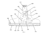
- FIG. 1 illustrates the structure of the shower of the first embodiment of the present invention.
- FIG. 2 illustrates the breakdown structure of the shower of the first embodiment of the present invention in one view.
- FIG. 3 illustrates the breakdown structure of the shower of the first embodiment of the present invention in another view.
- FIG. 4 illustrates one sectional view of the shower of the first embodiment of the present invention.
- FIG. 5 illustrates another sectional view of the shower of the first embodiment of the present invention.
- FIG. 6 illustrates partial sectional view of the shower of the first embodiment of the present invention.
- FIG. 7 illustrates the power device of the shower of the first embodiment of the present invention.
- FIG. 8 illustrates the control principle of the shower of the first embodiment of the present invention.
- FIG. 9 illustrates the processing unit of the first embodiment of the present invention.
- FIG. 10 illustrates the diagram of the touch processing circuit of the first embodiment of the present invention.
- FIG. 11 illustrates the diagram of the rectifier and filter circuit and the voltage reduction and stabilizing circuit of the first embodiment of the present invention.
- FIG. 12 illustrates the diagram of the driving circuit of the first embodiment of the present invention.
- FIG. 13 illustrates the diagram of the revolution detecting module of the first embodiment of the present invention.
- FIG. 14 illustrates the diagram of the LED indicating light of the first embodiment of the present invention.
- FIG. 15 illustrates the sectional view of the shower of the second embodiment of the present invention.
- FIG. 16 illustrates the structure of the shower of the third embodiment of the present invention.
- a touch switch shower includes a shower body 100 and a switch control device 200 .
- the shower body 100 includes a housing 110 , a joint 120 , a fixation seat 130 , a valve seat 140 , a water diversion body 150 and an outlet cover unit 160 .
- the housing 110 is horn shaped.
- the fixation seat 130 is concaved and disposed with an assembly groove 131 , an impeller cover 132 is further disposed to cover the opening of the assembly groove 131 .
- the upper part of the fixation seat 130 is extended out of the housing 110 from down to up.
- the joint 120 is fixed to the extended part of fixation seat 130 extended out of the housing 110 , to make: the housing 110 , the joint 120 and the fixation seat 130 to be fixed together; the shower body 100 disposed with a root waterway 170 to connect to the water resource.
- the assembly groove 131 of the fixation seat 130 is one part of the root waterway 170 .
- the valve seat 140 is fixed to the lower part of the fixation seat 130 , the outer revolution surface of the valve seat 140 is fixed to the lower end of the inside revolution surface of the housing 110 .
- the water diversion body 150 is fixed to the lower of the valve seat 140
- the outlet cover unit 160 is fixed to the lower of the valve seat 140 , to make three outlet cavities of concentrically arranged formed between the water diversion body 150 and the outlet cover unit 160 ;
- the valve seat 140 is disposed with three diversion waterways 180 separately connected to the three outlet cavities, an electromagnetic valve 191 , 192 , 193 is separately disposed between each diversion waterway 180 and the root waterway 170 , the on-off of the each diversion waterway 180 is separately controlled by the electromagnetic valve 191 , 192 , 193 to make the outlet cavity to connect to the root waterway 170 .
- the outlet cover unit 160 is disposed with three outlet covers 161 , 162 , 163 of concentrically arranged, the three outlet covers 161 , 162 , 163 are corresponding to the three outlet cavities one by one, to make water of the three outlet cavities to flow out of the three outlet covers 161 , 162 , 163 .
- the edge of the back side of each outlet cover 161 , 162 , 163 is disposed with a limited cylinder 164 , 165 , 166 with the axis parallel to the axis of the concentric circle, the limited cylinders 164 , 165 , 166 are fixed to the valve seat 140 and are running through the valve seat 140 .
- the switch control device 200 is disposed with a processing unit 210 , three touch modules 221 , 222 , 223 , a power device 220 , three driving modules 191 , 192 , 193 and a revolution detecting module 230 .
- the processing unit 210 is applied with the microcontroller PIC16F913, as figured in the FIG. 9 .
- Each touch module 221 , 222 , 223 is separately disposed with a touch processing circuit 2211 , 2221 , 2231 and a touch layer, the diagram of the touch processing circuit is figured in the FIG. 10 .
- the touch layer of the three touch module 221 , 222 , 223 is separately electroplated to the front side of the outlet cover 161 , 162 , 163 to form three touch areas, so that touch operation is realized when the user touched different touch area.
- the limited cylinder 164 , 165 , 166 is coated with signal connection layer, which is connected to the touch processing circuit and the touch layer in signal way.
- One end of the three touch processing circuits is separately connected to the pin RC 5 of the processing unit 210 in signal way, while the other end is separately connected to the pin RA 2 , RA 0 , RA 1 of the processing unit 210 in signal way; thereinto: the pin RC 5 of the processing unit 210 is provided pulsing signal of 200 KHz to the touch processing circuit 2211 , 2221 , 2231 , when touched, the pulsing signal is bypassed by the body capacitance and then the level of the output of the touch module changes, the processing unit detects the change of the level to catch the touch signal.
- the power device 220 includes a power generating module 270 and a battery module 250 electrically connected to the power generating module 270 , the battery module 250 is electrically connected to the processing unit 210 to supply power to the processing unit 210 .
- the power generating module 270 is disposed with an impeller 271 rotated and disposed inside the assembly groove 131 of the root waterway and a generator 272 fixed to the fixation seat, the impeller is rotated relatively to the generator under the force of the water flow. To ensure the flow force, the connection opening of the assembly groove is inclined.
- a rectifier and filter circuit 273 and a voltage reduction and stabilizing circuit 274 are connected between the output of the generator 272 and the battery module 250 , the diagram is figured out in the FIG. 11 . In this embodiment, it applied with the power generating module 270 and the battery module 250 as the power device 220 , but not limited, other external power is available.
- the diagram of the three driving modules 191 , 192 , 193 is figured out in the FIG. 12 .
- the three driving modules 191 , 192 , 193 are separately connected to three signal output of the processing unit 210 .
- the driving module is disposed at least an amplifier to amplify the signal of the signal output to a signal to control the electromagnetic valve.
- the revolution detecting module 230 is connected to the processing unit 210 in signal way.
- the diagram is figured out in FIG. 13 .
- the revolution detecting module 230 is used to detect the water state, but not limited, other flow transducer or water pressure transducer is available in this embodiment.
- an LED indicating light 260 is further disposed to connect to the processing unit in signal way. Refer to the FIG. 14 .
- FIG. 15 which illustrates the structure of the second embodiment
- the difference from the previous embodiment is as below:
- a water diversion body 300 is rotated and disposed inside the shower body.
- the water diversion body 300 is disposed with a through hole, one end of the through hole is connected to the root waterway 170 , while the other end is alternately connected to the three diversion waterways 180 .
- the three diversion waterways 180 are switched to connect to the root waterway 170 .
- the switch control device 200 is disposed at least a processing unit 210 , three touch module 221 , 222 , 223 , a power device 220 connected to the processing unit 210 and a motor 280 .
- the touch layer of the three touch modules is separately disposed in the corresponding outlet cover 161 , 162 , 163 .
- the processing unit 210 is connected to the touch module in signal way, the processing unit 210 is connected to the motor 280 in signal way, the motor 280 is connected to the water diversion body 300 .
- the processing unit controls the motor to rotate in a first angle, water flows out of the first diversion waterway; when the touch layer of the outlet cover 162 is touched, the processing unit controls the motor to rotate in a second angle, water flows out of the second diversion waterway; when the touch layer of the outlet cover 163 is touched, the processing unit controls the motor to rotate in a third angle, water flows out of the third diversion waterway.
- the power device 220 is disposed with a lead 224 electrically connected to the processing unit and a plug 225 connected to the lead 224 , the plug 225 can connect to an outer power resource.
- the present invention is provided with a touch switch shower, in which the touch layer of the touch modules is separately disposed in the touch area of the outlet cover unit, the touch area is large enough for the user to operate.
- the operation is convenient and accurate with low cost, and the size of the shower is reduced.
- touch layers are corresponding to the electromagnetic valves one by one, which is convenient to control.
- the outlet type is with multi-combination.
- the present invention is provided with well industrial applicability.
Landscapes
- Engineering & Computer Science (AREA)
- General Engineering & Computer Science (AREA)
- Chemical & Material Sciences (AREA)
- Analytical Chemistry (AREA)
- Physics & Mathematics (AREA)
- Electromagnetism (AREA)
- Mechanical Engineering (AREA)
- Domestic Plumbing Installations (AREA)
- Bathtubs, Showers, And Their Attachments (AREA)
Abstract
Description
2. The several outlet covers forms different outlets, the front sides of the outlet covers forms the touch areas, each touch layer is clearly disposed, the outlet cover is corresponding to the diversion waterway one by one for the user to control accurately and conveniently.
3. The power device includes a power generating module and a battery module, the battery module is electrically connected to the processing unit, to ensure that it still works in lower water pressure.
4. A rectifier and filter circuit and a voltage reducing and stabilizing circuit are disposed between the output of the power generating and the battery module, to ensure the stabilized DC.
5. The back side of each outlet cover is convex and disposed with a connection cylinder, which is coated with a signal connection layer, the connection cylinder is applied with limited effect and signal connected effect.
6. The processing unit is further connected with an LED indicating light in signal way for user to see the working state of the processing unit or the electromagnetic valve.
7. When user touches different touch layer, the motor rotates in different angle to rotate the water diversion body to rotate relatively to the shower body in different angle, making different diversion waterways switched to connect to the root waterway, the switch is fast and convenient with small size.
Claims (11)
Applications Claiming Priority (4)
| Application Number | Priority Date | Filing Date | Title |
|---|---|---|---|
| CN2010205331652U CN201815400U (en) | 2010-09-16 | 2010-09-16 | Sprinkler switched by means of touching front cover |
| CN201020533165U | 2010-09-16 | ||
| CN201020533165.2 | 2010-09-16 | ||
| PCT/CN2011/079601 WO2012034512A1 (en) | 2010-09-16 | 2011-09-14 | Touch panel switched spray head |
Publications (2)
| Publication Number | Publication Date |
|---|---|
| US20130168583A1 US20130168583A1 (en) | 2013-07-04 |
| US8991432B2 true US8991432B2 (en) | 2015-03-31 |
Family
ID=43913372
Family Applications (1)
| Application Number | Title | Priority Date | Filing Date |
|---|---|---|---|
| US13/823,660 Expired - Fee Related US8991432B2 (en) | 2010-09-16 | 2011-09-14 | Touch switch shower |
Country Status (3)
| Country | Link |
|---|---|
| US (1) | US8991432B2 (en) |
| CN (1) | CN201815400U (en) |
| WO (1) | WO2012034512A1 (en) |
Cited By (25)
| Publication number | Priority date | Publication date | Assignee | Title |
|---|---|---|---|---|
| US20170320072A1 (en) * | 2016-05-06 | 2017-11-09 | Xiamen Runner Industrial Corporation | Multi touch control type water output switching shower device |
| US20180193852A1 (en) * | 2017-01-09 | 2018-07-12 | As Ip Holdco, Llc | Touch Controlled Shower Head |
| US10130959B1 (en) * | 2017-07-10 | 2018-11-20 | Kylin Sanitary Technology (Xiamen) Co., Ltd. | Shower unit with easy to change water outflow rate |
| USD844749S1 (en) * | 2017-12-22 | 2019-04-02 | Phoenix Industries Pty Ltd | Hand shower |
| USD846696S1 (en) * | 2017-06-28 | 2019-04-23 | Phoenix Industries Pty Ltd | Hand shower |
| USD847302S1 (en) * | 2017-06-28 | 2019-04-30 | Phoenix Industries Pty Ltd | Hand shower |
| USD849191S1 (en) | 2017-06-28 | 2019-05-21 | Phoenix Industries Pty Ltd | Shower rose |
| USD851207S1 (en) | 2017-06-28 | 2019-06-11 | Phoenix Industries Pty Ltd | Shower rose |
| USD888195S1 (en) * | 2017-06-28 | 2020-06-23 | Phoenix Industries Pty Ltd. | Shower rose |
| USD902346S1 (en) | 2019-02-22 | 2020-11-17 | Phoenix Industries Pty Ltd. | Twin showers |
| USD926287S1 (en) | 2019-02-22 | 2021-07-27 | Phoenix Industries Pty Ltd | Shower head |
| USD926925S1 (en) | 2019-02-22 | 2021-08-03 | Phoenix Industries Pty Ltd | Shower head |
| USD926924S1 (en) | 2019-02-22 | 2021-08-03 | Phoenix Industries Pty Ltd | Shower rose |
| USD927638S1 (en) | 2019-02-22 | 2021-08-10 | Phoenix Industries Pty Ltd | Shower rose |
| USD934381S1 (en) * | 2020-01-21 | 2021-10-26 | Grohe Ag | Shower head |
| USD939047S1 (en) | 2019-02-22 | 2021-12-21 | Phoenix Industries Pty Ltd | Rail shower |
| USD939046S1 (en) | 2019-02-22 | 2021-12-21 | Phoenix Industries Pty Ltd | Hand shower |
| USD939664S1 (en) | 2019-02-22 | 2021-12-28 | Phoenix Industries Pty Ltd | Hand shower |
| USD942599S1 (en) | 2019-02-22 | 2022-02-01 | Phoenix Industries Pty Ltd | Hand shower bracket |
| USD943709S1 (en) | 2019-02-22 | 2022-02-15 | Phoenix Industries Pty Ltd | Twin showers |
| USD954900S1 (en) | 2019-02-22 | 2022-06-14 | Phoenix Industries Pty Ltd | Rail shower |
| USD960302S1 (en) | 2017-06-28 | 2022-08-09 | Phoenix Industries Pty Ltd | Shower head |
| USD961046S1 (en) * | 2020-09-07 | 2022-08-16 | Xiamen Delmei Sanitary Ware Co., Ltd. | Shower head |
| USD972078S1 (en) * | 2022-08-01 | 2022-12-06 | Jiansen Chen | Shower spray jet |
| USD972922S1 (en) | 2019-02-22 | 2022-12-20 | Phoenix Industries Pty Ltd | Hand shower bracket |
Families Citing this family (18)
| Publication number | Priority date | Publication date | Assignee | Title |
|---|---|---|---|---|
| CN201815400U (en) | 2010-09-16 | 2011-05-04 | 厦门松霖科技有限公司 | Sprinkler switched by means of touching front cover |
| CN102553736A (en) * | 2011-12-23 | 2012-07-11 | 厦门松霖科技有限公司 | Shower with sliding contact-controlled water passages |
| WO2013091500A1 (en) * | 2011-12-23 | 2013-06-27 | 厦门松霖科技有限公司 | Intelligent feedback mechanism and method for switching water passage |
| CN104138813B (en) * | 2013-05-08 | 2017-02-08 | 厦门松霖科技有限公司 | Sprinkler with multiple water-outlet functions |
| CN103949360B (en) * | 2014-04-23 | 2016-05-25 | 厦门建霖工业有限公司 | A kind of device and method that utilizes current button to realize switching controls |
| US9416764B1 (en) * | 2015-06-30 | 2016-08-16 | Nikhil Dubbaka | Fluid flow power switch |
| EP3147029B1 (en) * | 2015-09-25 | 2020-06-03 | Zhejiang Huale Technology Co.,Ltd. | Inductive showerhead and multi-waterway switching mechanism |
| CN105170355B (en) * | 2015-09-29 | 2018-10-09 | 福建西河卫浴科技有限公司 | A kind of discharging device of self power generation |
| US20180085763A1 (en) * | 2016-09-27 | 2018-03-29 | Erik Leckner | Electronic Nozzle |
| CN106238236B (en) * | 2016-09-28 | 2022-11-18 | 福建西河卫浴科技有限公司 | Shower head easy to touch and switch and control method |
| CN206199521U (en) | 2016-09-28 | 2017-05-31 | 福建西河卫浴科技有限公司 | A kind of easy gondola water faucet for touching switching |
| CN107269913A (en) * | 2017-05-16 | 2017-10-20 | 郝朝朝 | A kind of self power generation electromagnetic induction discharging device |
| TWM560545U (en) * | 2017-05-26 | 2018-05-21 | Agreat Shower & Sanitary Xiamen Co Ltd | Temperature sensing display device of faucet |
| CN108061181A (en) * | 2018-01-15 | 2018-05-22 | 东莞市适意洁具有限公司 | Waterway switching device |
| CN210815919U (en) * | 2019-08-16 | 2020-06-23 | 路达(厦门)工业有限公司 | Water outlet device capable of generating electricity and provided with lamp light |
| DE202019106865U1 (en) * | 2019-12-10 | 2021-03-12 | Viega Technology Gmbh & Co. Kg | Device for delivering and / or distributing a water volume flow and water supply system |
| USD1025292S1 (en) * | 2021-03-17 | 2024-04-30 | Grohe Ag | Shower head |
| USD1020997S1 (en) * | 2023-12-29 | 2024-04-02 | Xiamen Galenpoo Kitchen & Bathroom Technology Co., Ltd | Filter |
Citations (10)
| Publication number | Priority date | Publication date | Assignee | Title |
|---|---|---|---|---|
| CN201264006Y (en) | 2008-09-17 | 2009-07-01 | 王永进 | Multifunctional shower |
| CN201316206Y (en) | 2008-10-30 | 2009-09-30 | 洪光明 | Novel touch intelligent control type conceal-mounted constant temperature shower |
| US20090314358A1 (en) | 2006-04-07 | 2009-12-24 | Dlp Limited | Electric showers |
| CN101733208A (en) | 2009-12-31 | 2010-06-16 | 厦门松霖科技有限公司 | Shower head employing electronic touch to control water rout switching |
| CN201572692U (en) | 2009-12-31 | 2010-09-08 | 厦门松霖科技有限公司 | Sprinkler adopting electronic touch for controlling water channel switchover |
| CN201815400U (en) | 2010-09-16 | 2011-05-04 | 厦门松霖科技有限公司 | Sprinkler switched by means of touching front cover |
| US8118240B2 (en) * | 2006-04-20 | 2012-02-21 | Masco Corporation Of Indiana | Pull-out wand |
| US8132778B2 (en) * | 2008-04-22 | 2012-03-13 | Connors Paul E | Remote control water valving system for shower or sink |
| US8243040B2 (en) * | 2006-04-20 | 2012-08-14 | Masco Corporation Of Indiana | Touch sensor |
| US8297538B2 (en) * | 2008-05-23 | 2012-10-30 | Zhou Huasong | Shower switch with adjustable device |
-
2010
- 2010-09-16 CN CN2010205331652U patent/CN201815400U/en not_active Expired - Fee Related
-
2011
- 2011-09-14 US US13/823,660 patent/US8991432B2/en not_active Expired - Fee Related
- 2011-09-14 WO PCT/CN2011/079601 patent/WO2012034512A1/en active Application Filing
Patent Citations (10)
| Publication number | Priority date | Publication date | Assignee | Title |
|---|---|---|---|---|
| US20090314358A1 (en) | 2006-04-07 | 2009-12-24 | Dlp Limited | Electric showers |
| US8118240B2 (en) * | 2006-04-20 | 2012-02-21 | Masco Corporation Of Indiana | Pull-out wand |
| US8243040B2 (en) * | 2006-04-20 | 2012-08-14 | Masco Corporation Of Indiana | Touch sensor |
| US8132778B2 (en) * | 2008-04-22 | 2012-03-13 | Connors Paul E | Remote control water valving system for shower or sink |
| US8297538B2 (en) * | 2008-05-23 | 2012-10-30 | Zhou Huasong | Shower switch with adjustable device |
| CN201264006Y (en) | 2008-09-17 | 2009-07-01 | 王永进 | Multifunctional shower |
| CN201316206Y (en) | 2008-10-30 | 2009-09-30 | 洪光明 | Novel touch intelligent control type conceal-mounted constant temperature shower |
| CN101733208A (en) | 2009-12-31 | 2010-06-16 | 厦门松霖科技有限公司 | Shower head employing electronic touch to control water rout switching |
| CN201572692U (en) | 2009-12-31 | 2010-09-08 | 厦门松霖科技有限公司 | Sprinkler adopting electronic touch for controlling water channel switchover |
| CN201815400U (en) | 2010-09-16 | 2011-05-04 | 厦门松霖科技有限公司 | Sprinkler switched by means of touching front cover |
Cited By (26)
| Publication number | Priority date | Publication date | Assignee | Title |
|---|---|---|---|---|
| US20170320072A1 (en) * | 2016-05-06 | 2017-11-09 | Xiamen Runner Industrial Corporation | Multi touch control type water output switching shower device |
| US20180193852A1 (en) * | 2017-01-09 | 2018-07-12 | As Ip Holdco, Llc | Touch Controlled Shower Head |
| US10625279B2 (en) * | 2017-01-09 | 2020-04-21 | As America, Inc. | Touch controlled shower head |
| USD846696S1 (en) * | 2017-06-28 | 2019-04-23 | Phoenix Industries Pty Ltd | Hand shower |
| USD847302S1 (en) * | 2017-06-28 | 2019-04-30 | Phoenix Industries Pty Ltd | Hand shower |
| USD849191S1 (en) | 2017-06-28 | 2019-05-21 | Phoenix Industries Pty Ltd | Shower rose |
| USD851207S1 (en) | 2017-06-28 | 2019-06-11 | Phoenix Industries Pty Ltd | Shower rose |
| USD888195S1 (en) * | 2017-06-28 | 2020-06-23 | Phoenix Industries Pty Ltd. | Shower rose |
| USD960302S1 (en) | 2017-06-28 | 2022-08-09 | Phoenix Industries Pty Ltd | Shower head |
| US10130959B1 (en) * | 2017-07-10 | 2018-11-20 | Kylin Sanitary Technology (Xiamen) Co., Ltd. | Shower unit with easy to change water outflow rate |
| USD844749S1 (en) * | 2017-12-22 | 2019-04-02 | Phoenix Industries Pty Ltd | Hand shower |
| USD926925S1 (en) | 2019-02-22 | 2021-08-03 | Phoenix Industries Pty Ltd | Shower head |
| USD954900S1 (en) | 2019-02-22 | 2022-06-14 | Phoenix Industries Pty Ltd | Rail shower |
| USD926924S1 (en) | 2019-02-22 | 2021-08-03 | Phoenix Industries Pty Ltd | Shower rose |
| USD927638S1 (en) | 2019-02-22 | 2021-08-10 | Phoenix Industries Pty Ltd | Shower rose |
| USD972922S1 (en) | 2019-02-22 | 2022-12-20 | Phoenix Industries Pty Ltd | Hand shower bracket |
| USD939047S1 (en) | 2019-02-22 | 2021-12-21 | Phoenix Industries Pty Ltd | Rail shower |
| USD939046S1 (en) | 2019-02-22 | 2021-12-21 | Phoenix Industries Pty Ltd | Hand shower |
| USD939664S1 (en) | 2019-02-22 | 2021-12-28 | Phoenix Industries Pty Ltd | Hand shower |
| USD942599S1 (en) | 2019-02-22 | 2022-02-01 | Phoenix Industries Pty Ltd | Hand shower bracket |
| USD943709S1 (en) | 2019-02-22 | 2022-02-15 | Phoenix Industries Pty Ltd | Twin showers |
| USD926287S1 (en) | 2019-02-22 | 2021-07-27 | Phoenix Industries Pty Ltd | Shower head |
| USD902346S1 (en) | 2019-02-22 | 2020-11-17 | Phoenix Industries Pty Ltd. | Twin showers |
| USD934381S1 (en) * | 2020-01-21 | 2021-10-26 | Grohe Ag | Shower head |
| USD961046S1 (en) * | 2020-09-07 | 2022-08-16 | Xiamen Delmei Sanitary Ware Co., Ltd. | Shower head |
| USD972078S1 (en) * | 2022-08-01 | 2022-12-06 | Jiansen Chen | Shower spray jet |
Also Published As
| Publication number | Publication date |
|---|---|
| CN201815400U (en) | 2011-05-04 |
| US20130168583A1 (en) | 2013-07-04 |
| WO2012034512A1 (en) | 2012-03-22 |
Similar Documents
| Publication | Publication Date | Title |
|---|---|---|
| US8991432B2 (en) | Touch switch shower | |
| WO2017190407A1 (en) | Multipoint touch-enabled water spray mode switching shower and method | |
| CN103968105B (en) | A kind of hydroseparator structure and the gondola water faucet with hydroseparator structure | |
| CN110167678B (en) | Touch control type shower nozzle | |
| US10618064B2 (en) | Multi-functional shower | |
| US20170089317A1 (en) | Water outlet device of self power generation | |
| US8336398B2 (en) | Pipe connection having a flow counting function | |
| JP3168285U (en) | Alarm indicator lamp for water supply equipment | |
| CN105202249A (en) | Sensing rotary faucet and water outlet control thereof | |
| WO2017190408A1 (en) | Single-point touch-enabled water spray mode switching shower | |
| US8181512B2 (en) | Timing device having a flow control function | |
| WO2019119921A1 (en) | Shower head capable of switching water spray mode through shake-based touch sensing | |
| US20140008464A1 (en) | Shower | |
| CN206903388U (en) | A kind of lock-switch mechanism, lock assembly and bicycle | |
| WO2013091501A1 (en) | Shower with sliding contact-controlled water passages | |
| CN205815965U (en) | One extremely letter rotates water bloom structure | |
| CN209705397U (en) | A kind of valve with flow sensor | |
| TWI553253B (en) | Capacitive induction type water supply device and method | |
| CN207879471U (en) | Handle controller | |
| CN206409711U (en) | Determine angle driving apparatus and with the gas-liquid switching valve for determining angle driving apparatus | |
| CN106040473B (en) | The electric air pump handle cover of sprayer | |
| CN106238236B (en) | Shower head easy to touch and switch and control method | |
| CN217355807U (en) | Temperature-variable luminous pull faucet | |
| CN206534568U (en) | A kind of Multifunctional shower bath device | |
| CN208554651U (en) | A kind of shower bath |
Legal Events
| Date | Code | Title | Description |
|---|---|---|---|
| AS | Assignment |
Owner name: XIAMEN SOLEX HIGH-TECH INDUSTRIES CO., LTD., CHINA Free format text: ASSIGNMENT OF ASSIGNORS INTEREST;ASSIGNORS:ZHOU, HUASONG;LU, GUOQIANG;SUN, XIAOZHAO;AND OTHERS;REEL/FRAME:030004/0912 Effective date: 20130308 Owner name: ZHOU, HUASONG, CHINA Free format text: ASSIGNMENT OF ASSIGNORS INTEREST;ASSIGNORS:ZHOU, HUASONG;LU, GUOQIANG;SUN, XIAOZHAO;AND OTHERS;REEL/FRAME:030004/0912 Effective date: 20130308 |
|
| STCF | Information on status: patent grant |
Free format text: PATENTED CASE |
|
| AS | Assignment |
Owner name: XIAMEN SOLEX HIGH-TECH INDUSTRIES CO., LTD., CHINA Free format text: ASSIGNMENT OF ASSIGNORS INTEREST;ASSIGNORS:XIAMEN SOLEX HIGH-TECH INDUSTRIES CO., LTD.;ZHOU, HUASONG;REEL/FRAME:044599/0786 Effective date: 20171116 |
|
| MAFP | Maintenance fee payment |
Free format text: PAYMENT OF MAINTENANCE FEE, 4TH YEAR, LARGE ENTITY (ORIGINAL EVENT CODE: M1551); ENTITY STATUS OF PATENT OWNER: LARGE ENTITY Year of fee payment: 4 |
|
| FEPP | Fee payment procedure |
Free format text: MAINTENANCE FEE REMINDER MAILED (ORIGINAL EVENT CODE: REM.); ENTITY STATUS OF PATENT OWNER: LARGE ENTITY |
|
| LAPS | Lapse for failure to pay maintenance fees |
Free format text: PATENT EXPIRED FOR FAILURE TO PAY MAINTENANCE FEES (ORIGINAL EVENT CODE: EXP.); ENTITY STATUS OF PATENT OWNER: LARGE ENTITY |
|
| STCH | Information on status: patent discontinuation |
Free format text: PATENT EXPIRED DUE TO NONPAYMENT OF MAINTENANCE FEES UNDER 37 CFR 1.362 |
|
| FP | Lapsed due to failure to pay maintenance fee |
Effective date: 20230331 |