US8976541B2 - Electrical power and data distribution apparatus - Google Patents
Electrical power and data distribution apparatus Download PDFInfo
- Publication number
- US8976541B2 US8976541B2 US13/599,994 US201213599994A US8976541B2 US 8976541 B2 US8976541 B2 US 8976541B2 US 201213599994 A US201213599994 A US 201213599994A US 8976541 B2 US8976541 B2 US 8976541B2
- Authority
- US
- United States
- Prior art keywords
- data
- power
- electrical power
- enclosure
- connector
- Prior art date
- Legal status (The legal status is an assumption and is not a legal conclusion. Google has not performed a legal analysis and makes no representation as to the accuracy of the status listed.)
- Expired - Fee Related, expires
Links
Images


Classifications
-
- H—ELECTRICITY
- H02—GENERATION; CONVERSION OR DISTRIBUTION OF ELECTRIC POWER
- H02G—INSTALLATION OF ELECTRIC CABLES OR LINES, OR OF COMBINED OPTICAL AND ELECTRIC CABLES OR LINES
- H02G3/00—Installations of electric cables or lines or protective tubing therefor in or on buildings, equivalent structures or vehicles
- H02G3/02—Details
- H02G3/08—Distribution boxes; Connection or junction boxes
- H02G3/18—Distribution boxes; Connection or junction boxes providing line outlets
Definitions
- the following disclosure relates the connection of devices to a data network, and in particular, to an apparatus for the distribution of electrical power and network communications to devices in a building, e.g., in a commercial or residential building.
- Providing a unified network for handling both digital communications and electrical power distribution in a commercial or residential building is the goal of many developers.
- it is desired to simplify the connection of non-network enabled devices into a digital communication network.
- It is also desired to eliminate the requirement to provide separate wiring for electrical power (i.e., general-purpose alternating current electric power supply, also known as, e.g., “wall outlet power”, “grid power” or “mains power”) and network communications in a building.
- U.S. Pat. No. 7,940,673 published as U.S. Patent Application Publication No. 2009/0016216 and entitled System For Integrating A Plurality Of Modules Using A Power/Data Backbone Network discloses an architecture for the modular connection of devices to a unified power/data network.
- U.S. Pat. No. 7,740,501 published as U.S. Patent Application Publication No. 2009/0011639 and entitled Hybrid Cable For Conveying Data And Power discloses cables for providing electrical power and network data to the devices in a network.
- U.S. application Ser. No. 12/820,875 published as U.S. Patent Application Publication No. 2010/0319956 and entitled Hybrid Cable For Conveying Data And Power discloses addition cables for providing electrical power and network data to the devices in a network.
- an electrical power and data distribution apparatus comprises an enclosure configured for installation in a wall of a building.
- the enclosure includes a front surface and a rear surface.
- a rear power/data connector is mounted on the rear surface of the enclosure and configured to electrically connect to a first hybrid external cable including both electrical power conductors and network data conductors.
- a front power/data connector is mounted on the front surface of the enclosure and configured to electrically connect to a second hybrid external cable including both electrical power conductors and network data conductors.
- At least one electrical power outlet is mounted on the front surface of the enclosure and configured to electrically connect to a standard wall outlet power plug.
- At least one data input/output connector is mounted on the front surface of the enclosure and configured to connect to an external device having a predetermined connection configuration.
- a power hub is disposed inside the enclosure and operatively connected to the rear power/data connector to receive electrical power therefrom and operatively connected to the front power/data connector and the electrical power outlet to supply electrical power thereto.
- a controller system is disposed inside the enclosure, the controller system including a processor, a memory, a network interface and an input/output section.
- the network data conductors of the rear power/data jack and the front power/data jack are operatively connected to the network interface of the controller system for sending and receiving network data therebetween in accordance with a first communication protocol and the data input/output connector is operatively connected to the input/output section of the controller system for sending and receiving data therebetween in accordance with a second communication protocol.
- the power hub is connected to the controller system for receiving control signals therefrom and adapted to selectively control the flow of electrical power to the electrical power outlet or to the front power/data connector in response to the control signals received from the controller system.
- the data input/output port is a high definition multimedia interface (HDMI) port implementing the EIA/CEA-861 standards.
- HDMI high definition multimedia interface
- the data input/output port is a universal serial bus (USB) port implementing the USB standards.
- USB universal serial bus
- the data input/output port is a RJ-45 jack implementing the Ethernet network communication standards.
- the distribution apparatus further comprises a wireless communication module disposed within the enclosure and operatively connected to the controller system for sending and receiving data signals therebetween.
- an electrical power and data distribution apparatus comprises an enclosure configured for installation in a wall of a building.
- the enclosure includes a front surface and a rear surface.
- a rear electrical power connector is mounted on the rear surface of the enclosure and configured to electrically connect to electrical wall outlet power source.
- a front power/data connector is mounted on the front surface of the enclosure and configured to electrically connect to a second hybrid external cable including both electrical power conductors and network data conductors.
- At least one electrical power outlet is mounted on the front surface of the enclosure and configured to electrically connect to a standard wall outlet power plug.
- At least one data input/output connector is mounted on the front surface of the enclosure and configured to connect to an external device having a predetermined connection configuration.
- a power hub is disposed inside the enclosure and operatively connected to the rear electrical power connector to receive electrical power therefrom and operatively connected to the front power/data connector and the electrical power outlet to supply electrical power thereto.
- a wireless communication module is disposed within the enclosure for sending and receiving data communications to/from an external wireless network.
- a controller system disposed inside the enclosure including a processor, a memory, a network interface and an input/output section.
- the network data conductors of the front power/data jack are operatively connected to the network interface of the controller system for sending and receiving network data therebetween in accordance with a first communication protocol;
- the wireless communication module is operatively connected to the controller system for sending and receiving network communications with an external wireless network;
- the data input/output connector is operatively connected to the input/output section of the controller system for sending and receiving data therebetween in accordance with a second communication protocol.
- the power hub is connected to the controller system for receiving control signals therefrom and adapted to selectively control the flow of electrical power to the electrical power outlet or to the front power/data connector in response to the control signals received from the controller system.
- FIGS. 1 a , 1 b and 1 c illustrate an electrical power and data distribution apparatus in accordance with one embodiment, specifically, FIG. 1 a being a front view, FIG. 1 b being a side view and FIG. 1 c being a rear view;
- FIG. 2 is a functional block diagram of the embodiment of FIG. 1 a;
- FIGS. 3 a , 3 b and 3 c illustrate an electrical power and data distribution apparatus in accordance with another embodiment, specifically, FIG. 3 a being a front view, FIG. 3 b being a side view and FIG. 3 c being a rear view;
- FIG. 4 is a front view of an electrical power and data distribution apparatus in accordance with a yet another embodiment
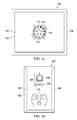
- FIG. 5 is a front view of an electrical power and data distribution apparatus in accordance with a further embodiment
- FIGS. 6 a , 6 b and 6 c illustrate an electrical power and data distribution apparatus in accordance with yet another embodiment, specifically, FIG. 6 a being a front view, FIG. 6 b being a side view and FIG. 6 c being a rear view; and
- FIG. 7 is a functional block diagram of the embodiment of FIG. 6 a.
- the distribution apparatus 100 has an enclosure 102 configured for installation in a cutout in a hollow wall using mounting means (not shown) similar to those used for conventional electrical boxes.
- the enclosure 102 includes a front surface 104 that is typically exposed to the room when the apparatus 100 is mounted in the wall and a rear surface 106 that typically faces the hollow space inside the wall (and thus is hidden from view when mounted).
- the enclosure 102 has dimensions substantially similar to those of conventional electrical boxes.
- the face of the rear surface 106 has dimensions of approximately 4′′ ⁇ 4′′ (width ⁇ height) and the depth of the enclosure is approximately 1.5′′ to 2.5′′.
- the front surface 104 may include a removable cover plate 108 having dimensions that are greater than the dimensions of the rear surface 106 , thereby covering the mounting hole in the wall.
- the cover plate 108 may have dimensions of approximately 4.6′′ ⁇ 4.5′′ (width ⁇ height).
- a rear power/data connector (or “jack”) 110 is mounted on the rear surface 106 of the enclosure 102 and configured to electrically connect to a first hybrid external cable (not shown) including both electrical power conductors and network data conductors.
- electrical power conductors are conductors carrying electrical voltage and current having no data component/signals used by the subject distribution apparatus; i.e., either the power conductors carry no data components/signals at all (e.g., pure AC or DC power), or the power conductors carry data components/signals that are not utilized by the distribution apparatus.
- Network data conductors are any type of conductors carrying network data signals that are utilized by the subject distribution apparatus.
- Such conductors may be electrical wires carrying electrical signals, optical fibers carrying light signals, or any other type of conductor capable of carrying network data.
- the rear connector 110 has a round profile and includes twelve power conductor sockets 112 and four network data conductor sockets 114 , each corresponding to a separate conductor pin in the associated hybrid cable.
- the rear connector 110 may have a different profile, e.g., square, rectangular, trapezoidal, etc., and different pin/socket numbers and configurations, as long as some of the conductors in the connector are power conductors and other conductors in the same connector are network data conductors.
- the rear power/data connector 110 may be configured to interface with external cables having the configurations disclosed in U.S. Pat. No. 7,740,501 and/or U.S. Patent Application Publication No. 2010/0319956.
- a front power/data connector (“jack”) 116 is mounted on the front surface 104 of the enclosure 102 and configured to electrically connect to a second hybrid external cable (not shown) including both electrical power conductors and network data conductors.
- the front power/data connector 116 has a round profile and includes twelve power conductor sockets 112 and four network data conductor sockets 114 , each corresponding to a separate conductor pin in the associated hybrid cable.
- the front connector 116 may have a different profile, e.g., square, rectangular, trapezoidal, etc., and different pin/socket numbers and configurations, as long as some of the conductors in the connector are power conductors and other conductors in the same connector are network data conductors.
- the front power/data connector 116 may have a configuration that is identical to the rear power/data connector 110 ; however, this is not required.
- the distribution apparatus 100 includes least one electrical power outlet 118 mounted on the front surface 104 of the enclosure 102 and configured to electrically connect to a standard wall outlet power plug (not shown).
- a standard wall outlet power plug (not shown).
- two power outlets 118 are provided, and each is configured to accept a standard North American 110 VAC three-prong wall outlet power plug.
- the power outlet(s) 118 may be configured to accept plugs having other configurations for different voltages, countries or special requirements. If multiple power outlets are provided on a single apparatus 100 , the configuration of each power outlet 118 on that apparatus may be the same or different from one another.
- the distribution apparatus 100 further includes at least one data input/output connector 120 mounted on the front surface 104 of the enclosure 102 and configured to connect to an external device (not shown) having a predetermined connection configuration.
- an external device not shown
- two input/output connectors are provided, namely, a first input/output connector (denoted 120 a ), which is a RJ-45 jack for the connection of Ethernet-compatible network communication devices, and a second input/output connector (denoted 120 b ), which is a high definition multimedia interface (HDMI) port for connection using the EIA/CEA-861 standards.
- input/output connectors 120 may be providing having other configurations, including, but not limited to, USB 1.0, USB 2.0, USB 3.0, Firewire 400, Firewire 800, Thunderbolt (Apple Corp.).
- the power hub 202 Disposed inside the enclosure 102 are a power hub 202 and a computer (or “controller”) system 204 .
- the power hub 202 is operatively connected to the rear power/data connector 110 to receive electrical power therefrom (denoted by arrow 206 ) and operatively connected to the front power/data connector 116 and the power outlets 118 to supply electrical power thereto (denoted by arrows 208 and 210 , respectively).
- the power hub 202 may supply electrical power to the front power/data connector 116 and power outlets 118 without modifying the character of the power (termed “pass-through”) or it may convert the character of the power, e.g., by changing the voltage level, by full-wave or half-wave rectification, etc. to some or all of the connectors/outlets.
- the controller system 204 controls the local operation of the distribution apparatus 100 .
- the controller system 204 may function according to dedicated programming (e.g., on-board firmware) and/or in response to instructions received over the associated digital communication network.
- the controller system 204 may include a central processing unit (“CPU”) 212 , a memory unit 214 , an input/output (“I/O”) device 216 , and a network interface 218 .
- the components 212 , 214 , 216 , and 218 are interconnected by a transport system (e.g., a bus) 220 .
- a dedicated power supply (“PS”) 222 may provide power to components of the controller system 204 , such as the CPU 212 and memory unit 214 .
- PS dedicated power supply
- controller system 204 may be differently configured in different embodiments, and that each of the listed components may actually represent multiple components.
- the CPU 212 may actually represent a micro-controller, microprocessor, multi-processor or a distributed processing system;
- the memory unit 214 may include different levels of cache memory, main memory, hard disks, and remote storage locations;
- the I/O device 216 may include analog, digital, analog-to-digital and digital-to-analog circuitry for interfacing with components inside and outside the enclosure;
- the network interface 218 may include one or more network cards providing one or more connections (wired and/or wireless) to various digital communication networks. Therefore, a wide range of flexibility is anticipated in the configuration of the controller system 204 .
- the controller system 204 may use any operating system (or multiple operating systems), including various versions of operating systems provided by Microsoft Corp. (e.g., WINDOWS), Apple Corp. (e.g., Mac OS X and iOS), UNIX, and LINUX, and may include operating systems specifically developed for handheld devices, personal computers, and servers depending on the use of the controller system 204 .
- the operating system, as well as other instructions, may be stored in the memory unit 214 and executed by the CPU 212 .
- the controller system 204 illustrated in FIG. 2 is just one possible example; many other configurations are possible.
- the network data conductors 114 of the rear power/data jack 110 and the front power/data jack 116 are operatively connected (denoted by arrows 224 and 226 , respectively) to the controller system 204 (e.g., via the network interface 218 ) for sending and receiving network data in accordance with a first communication protocol or standard.
- the controller system 204 is able to communicate with network devices connected to the rear power/data jack 110 and/or the front power/data jack 116 , and further facilitates network communication between devices connected to the power/data jacks, all using a first network communication standard, e.g., Ethernet.
- Each of the data input/output connectors 120 is also operatively connected (denoted by arrows 228 ) to the controller system 204 (e.g., via the input/output section 216 ) for sending and receiving data therebetween.
- the communication between the controller system 204 and the input/output connectors 120 may be in accordance with the same (i.e., first) communication standard used for the front and rear power/data connectors 116 , 110 , and/or it may be in accordance with a second communication protocol or standard. In the example illustrated in FIG.
- the controller system 204 may communicate with the first input/output connector 120 a using the first network communication standard, e.g., Ethernet, communicate with a second input/output connector 120 b using the HDMI communication standard, and communicate with a third input/output connector 120 c ( FIG. 5 ) using the USB communication standard.
- first network communication standard e.g., Ethernet
- second input/output connector 120 b using the HDMI communication standard
- third input/output connector 120 c FIG. 5
- communication including, but not limited to, signal conditioning, coding and decoding
- communication may be conducted by the controller system alone, while in other embodiments the communication may be facilitated by dedicated standard-specific interface circuitry 230 a , 230 b and 230 c , respectively, disposed on one or more of the communication paths.
- the power hub 202 may be operatively connected (denoted by arrow 231 ) to receive control signals from the controller system 204 , and adapted to selectively control the flow of electrical power to the electrical power outlets 118 and/or to the front power/data connector 116 in response to the control signals received from the controller system.
- controlling the flow of electrical power includes, but is not limited to: turning the flow of power on and off; changing the voltage supplied; and limiting the maximum current provided.
- the apparatus 100 may further comprise a wireless communication module 232 disposed within the enclosure 102 and operatively connected (denoted by arrow 234 ) to the controller system 204 to allow wireless network communication to/from the apparatus.
- Data and instructions received from the wireless communication module 232 may be routed to the wired network via the power/data connectors 110 , 116 and/or routed to the data input/output connectors 120 (or vice versa) similar to data and instructions received via the wired network.
- the wireless communication module may operate according to specifications including, but not limited to: Wireless A (802.11a), Wireless G (802.11g) and Wireless N (802.11n-draft and 802.11n-2009).
- the apparatus 100 may further comprise a power supply 236 disposed within the enclosure 102 to supply power to the various components, including, but not limited to: the controller system 204 , wireless communication module 232 and data input/output connectors 120 .
- the power supplied to the data input/output connectors 120 may include operating and/or charging power for connected devices.
- the power supply 236 may provide power of a single electrical character (i.e., voltage, waveform, current limit, etc.) or power of different electrical characters.
- the power supply 236 may embody conventional-type power supplies, including but not limited to: transformers, voltage regulators and switching power supplies.
- the power supply 236 may be operatively connected (denoted by arrow 238 ) to the controller system 204 to receive control signals from the controller system, and adapted to selectively change the flow of electrical power provided to the various components in response to the control signals received from the controller system.
- controlling the flow of electrical power includes, but is not limited to: turning the flow of power on and off; changing the voltage supplied; and limiting the maximum current provided.
- the distribution apparatus 300 includes many features substantially similar to those previously described in connection with the distribution apparatus 100 of FIGS. 1 a , 1 b and 1 c . Such features are number as in the previous discussion and will not be described again in details.
- the enclosure 302 of the distribution apparatus 300 is sized to resemble a “single gang” electrical box having a rear surface 106 with dimensions of approximately 2′′ ⁇ 4′′ (width ⁇ height) and a cover plate 108 with dimensions of approximately 2.8′′ ⁇ 4.5′′ (width ⁇ height).
- a rear power/data connector 110 is mounted on the rear surface 106 of the enclosure 102 ( FIGS.
- no front power/data connector 116 is provided on the front surface 104 of the distribution apparatus 300 .
- mounted on the front surface 104 of the enclosure 302 are a single electrical power outlet 118 , a first data input/output connector 120 a configured as a RJ-45 jack and a second input/output connector 120 b configured as a HDMI port.
- the internal function of the distribution apparatus may be similar to that illustrated in FIG. 2 , but modified in view of the provided connectors.
- Some embodiments of the distribution apparatus 300 may include the wireless communication module 232 allowing communication with wireless networks, while other embodiments may communicate only via the wired power/data connector 110 .
- the distribution apparatus 400 is substantially similar in many respects to the distribution apparatus 100 , including a rear power/data connector 110 mounted on the rear surface of the enclosure (see FIGS. 1 b and 1 c ). However, the distribution apparatus 400 provides additional input/output connectors 120 . Specifically, mounted on the front surface 104 of the enclosure 102 are two electrical power outlets 118 , two data input/output connectors 120 a configured as RJ-45 jacks and two input/output connectors 120 b configured as HDMI ports.
- the internal function of the distribution apparatus 400 may be similar to that illustrated in FIG. 2 , but modified in view of the provided connectors.
- Some embodiments of the distribution apparatus 400 may include the wireless communication module 232 allowing communication with wireless networks, while other embodiments may communicate only via the wired power/data connectors 110 and 116 .
- the distribution apparatus 500 is substantially similar in many respects to the distribution apparatus 100 , including a rear power/data connector 110 mounted on the rear surface of the enclosure (see FIGS. 1 b and 1 c ). However, the distribution apparatus 500 provides a different mix of input/output connectors 120 . Specifically, mounted on the front surface 104 of the enclosure 102 are two electrical power outlets 118 , one data input/output connectors 120 a configured as a RJ-45 jack, two input/output connectors 120 b configured as HDMI ports and two input/output connectors 120 c configured as USB ports.
- the internal function of the distribution apparatus 500 may be similar to that illustrated in FIG. 2 , but modified in view of the provided connectors. Some embodiments of the distribution apparatus 500 may include the wireless communication module 232 allowing communication with wireless networks, while other embodiments may communicate only via the wired power/data connectors 110 and 116 .
- the distribution apparatus 600 may be used in buildings having standard AC electrical wiring (wall outlet power or mains power) and a wireless communications network.
- the distribution apparatus 600 is substantially similar in many respects to the distribution apparatus 100 , however, as best seen in FIGS. 6 b and 6 c , there is no rear power/data connector. Instead, a rear electrical power connector 610 configured as a standard wall outlet-style plug 612 is mounted on the rear surface 606 of the enclosure 602 , and operatively connected as further described below (see FIG. 7 ).
- the rear electrical power connector 610 is adapted to receive ordinary electrical power (i.e., wall power or mains power), not network data for use by the distribution apparatus 600 .
- the rear electrical power connector 610 serves to physically support the apparatus 600 when it is plugged in to a wall outlet.
- the rear electrical power connector 610 is configured as a standard North American 110 VAC three-prong wall outlet power plug.
- the power connector 610 may be configured to the prong dimension standards for different voltages, countries or special requirements.
- an electric power cord (not shown) extending from the enclosure 602 may be provided, and the power connector 610 may be mounted on the end of the power cord rather than directly on the rear of the enclosure.
- the front surface 104 of the distribution apparatus 600 is similar to that of distribution apparatus 100 ; mounted thereon are a front power/data connector 116 , at least one electrical power outlet 118 and at least one data/input output connector 120 .
- a front power/data connector 116 mounted thereon are a front power/data connector 116 , at least one electrical power outlet 118 and at least one data/input output connector 120 .
- two electrical power outlets 118 are provided.
- one data input/output connector 120 a configured as a RJ-45 jack
- one input/output connector 120 b configured as a HDMI port
- the power hub 202 is operatively connected (denoted by arrow 611 ) to the rear electrical power connector 610 to receive electrical power therefrom and operatively connected to the front power/data connector 116 and the power outlets 118 to supply electrical power thereto (denoted by arrows 208 and 210 , respectively).
- the power hub 202 may supply electrical power to the front power/data connector 116 and power outlets 118 without modifying the character of the power or it may convert the character of the power.
- the wireless communication module 232 is operatively connected (denoted by arrow 234 ) to the controller system 204 to send and receive data therebetween, such data including data network communications.
- the wireless communication module 232 may operate according to specifications including, but not limited to: Wireless A (802.11a), Wireless G (802.11g) and Wireless N (802.11n-draft and 802.11n-2009).
- Data and instructions received from the wireless communication module 232 may be routed to the wired network via the power/data connector 116 and/or routed to the data input/output connectors 120 (or vice versa) similar to data and instructions received via the wired network.
- the controller system 204 of the distribution apparatus 600 may include a CPU 212 , a memory unit 214 , an I/O device 216 , and a network interface 218 .
- the components 212 , 214 , 216 , and 218 may be interconnected by a bus 220 .
- a dedicated power supply 222 may provide power to components of the controller system 204 , such as the CPU 212 and memory unit 214 .
- the network data conductors 114 ( FIG. 6 ) of the front power/data jack 116 are operatively connected (denoted by arrow 226 ) to the controller system 204 for sending and receiving network data in accordance with a first communication protocol or standard.
- the controller system 204 is able to communicate with network devices connected to the front power/data jack 116 using a first network communication standard, e.g., Ethernet. This allows network data received from a wireless network by the wireless communication module 232 (and the controller system 204 ) to be communicated onto the wired network via power/data jack 116 , and vice versa.
- a first network communication standard e.g., Ethernet.
- Each of the data input/output connectors 120 on the distribution apparatus 600 is operatively connected to the controller system 204 for sending and receiving data therebetween.
- the communication between the controller system 204 and the input/output connectors 120 may be in accordance with the first communication standard used for the front power/data connector 116 , and/or it may be in accordance with a second communication protocol or standard.
- the controller system 204 may communicate with the first input/output connector 120 a using the first network communication standard, e.g., Ethernet, communicate with a second input/output connector 120 b using the HDMI communication standard, and communicate with a third input/output connector 120 c ( FIG. 5 ) using the USB communication standard.
- the remaining functionality of the distribution apparatus 600 is similar to that previously described for apparatus 100 , 300 , etc.
Abstract
An electrical power and data distribution apparatus comprises an enclosure having a rear connector configured to connect to a first cable including electrical power and data conductors, a front connector configured to connect to a second cable including electrical and data conductors, at least one electrical power outlet configured to connect to a power plug and at least one data input/output connector configured to connect to a device having a predetermined connection configuration. A power hub is connected to the rear connector to receive electrical power, and to the front connector and the power outlet to supply electrical power. The data conductors of the front and rear connectors are connected to a network interface of a controller for sending and receiving data with a first protocol, and the data input/output connector is connected to an input/output section of the controller for sending and receiving data with a second protocol.
Description
This application claims benefit of U.S. Provisional Application No. 61/529,580, filed Aug. 31, 2011, and entitled ELECTRICAL POWER AND DATA DISTRIBUTION APPARATUS.
The following disclosure relates the connection of devices to a data network, and in particular, to an apparatus for the distribution of electrical power and network communications to devices in a building, e.g., in a commercial or residential building.
Providing a unified network for handling both digital communications and electrical power distribution in a commercial or residential building is the goal of many developers. In particular, it is desired to simplify the connection of non-network enabled devices into a digital communication network. It is also desired to eliminate the requirement to provide separate wiring for electrical power (i.e., general-purpose alternating current electric power supply, also known as, e.g., “wall outlet power”, “grid power” or “mains power”) and network communications in a building.
U.S. Pat. No. 7,940,673 published as U.S. Patent Application Publication No. 2009/0016216 and entitled System For Integrating A Plurality Of Modules Using A Power/Data Backbone Network discloses an architecture for the modular connection of devices to a unified power/data network. U.S. Pat. No. 7,740,501 published as U.S. Patent Application Publication No. 2009/0011639 and entitled Hybrid Cable For Conveying Data And Power discloses cables for providing electrical power and network data to the devices in a network. U.S. application Ser. No. 12/820,875 published as U.S. Patent Application Publication No. 2010/0319956 and entitled Hybrid Cable For Conveying Data And Power discloses addition cables for providing electrical power and network data to the devices in a network.
U.S. Pat. Nos. 7,940,673 and 7,740,501 and U.S. Patent Application Publication Nos. 2009/0016216, 2011/0176428, 2009/0011639 and 2010/0319956 are hereby incorporated by reference.
In one aspect thereof, an electrical power and data distribution apparatus comprises an enclosure configured for installation in a wall of a building. The enclosure includes a front surface and a rear surface. A rear power/data connector is mounted on the rear surface of the enclosure and configured to electrically connect to a first hybrid external cable including both electrical power conductors and network data conductors. A front power/data connector is mounted on the front surface of the enclosure and configured to electrically connect to a second hybrid external cable including both electrical power conductors and network data conductors. At least one electrical power outlet is mounted on the front surface of the enclosure and configured to electrically connect to a standard wall outlet power plug. At least one data input/output connector is mounted on the front surface of the enclosure and configured to connect to an external device having a predetermined connection configuration. A power hub is disposed inside the enclosure and operatively connected to the rear power/data connector to receive electrical power therefrom and operatively connected to the front power/data connector and the electrical power outlet to supply electrical power thereto. A controller system is disposed inside the enclosure, the controller system including a processor, a memory, a network interface and an input/output section. The network data conductors of the rear power/data jack and the front power/data jack are operatively connected to the network interface of the controller system for sending and receiving network data therebetween in accordance with a first communication protocol and the data input/output connector is operatively connected to the input/output section of the controller system for sending and receiving data therebetween in accordance with a second communication protocol.
In another aspect thereof, the power hub is connected to the controller system for receiving control signals therefrom and adapted to selectively control the flow of electrical power to the electrical power outlet or to the front power/data connector in response to the control signals received from the controller system.
In another aspect thereof, the data input/output port is a high definition multimedia interface (HDMI) port implementing the EIA/CEA-861 standards.
In another aspect thereof, the data input/output port is a universal serial bus (USB) port implementing the USB standards.
In another aspect thereof, the data input/output port is a RJ-45 jack implementing the Ethernet network communication standards.
In another aspect thereof, the distribution apparatus further comprises a wireless communication module disposed within the enclosure and operatively connected to the controller system for sending and receiving data signals therebetween.
In another aspect thereof, an electrical power and data distribution apparatus comprises an enclosure configured for installation in a wall of a building. The enclosure includes a front surface and a rear surface. A rear electrical power connector is mounted on the rear surface of the enclosure and configured to electrically connect to electrical wall outlet power source. A front power/data connector is mounted on the front surface of the enclosure and configured to electrically connect to a second hybrid external cable including both electrical power conductors and network data conductors. At least one electrical power outlet is mounted on the front surface of the enclosure and configured to electrically connect to a standard wall outlet power plug. At least one data input/output connector is mounted on the front surface of the enclosure and configured to connect to an external device having a predetermined connection configuration. A power hub is disposed inside the enclosure and operatively connected to the rear electrical power connector to receive electrical power therefrom and operatively connected to the front power/data connector and the electrical power outlet to supply electrical power thereto. A wireless communication module is disposed within the enclosure for sending and receiving data communications to/from an external wireless network. A controller system disposed inside the enclosure including a processor, a memory, a network interface and an input/output section. The network data conductors of the front power/data jack are operatively connected to the network interface of the controller system for sending and receiving network data therebetween in accordance with a first communication protocol; the wireless communication module is operatively connected to the controller system for sending and receiving network communications with an external wireless network; and the data input/output connector is operatively connected to the input/output section of the controller system for sending and receiving data therebetween in accordance with a second communication protocol.
In another aspect thereof, the power hub is connected to the controller system for receiving control signals therefrom and adapted to selectively control the flow of electrical power to the electrical power outlet or to the front power/data connector in response to the control signals received from the controller system.
For a more complete understanding, reference is now made to the following description taken in conjunction with the accompanying Drawings in which:
Referring now to the drawings, wherein like reference numbers are used herein to designate like elements throughout, the various views and embodiments of an electrical power and data distribution apparatus are illustrated and described, and other possible embodiments are described. The figures are not necessarily drawn to scale, and in some instances the drawings have been exaggerated and/or simplified in places for illustrative purposes only. One of ordinary skill in the art will appreciate the many possible applications and variations based on the following examples of possible embodiments.
Referring now to FIGS. 1 a, 1 b and 1 c, there is illustrated an electrical power and data distribution apparatus in accordance with one embodiment, specifically, an embodiment designed for recessed or semi-recessed installation in a hollow wall of a residential or commercial building. The distribution apparatus 100 has an enclosure 102 configured for installation in a cutout in a hollow wall using mounting means (not shown) similar to those used for conventional electrical boxes. The enclosure 102 includes a front surface 104 that is typically exposed to the room when the apparatus 100 is mounted in the wall and a rear surface 106 that typically faces the hollow space inside the wall (and thus is hidden from view when mounted). Preferably, the enclosure 102 has dimensions substantially similar to those of conventional electrical boxes. In one such embodiment, the face of the rear surface 106 has dimensions of approximately 4″×4″ (width×height) and the depth of the enclosure is approximately 1.5″ to 2.5″. The front surface 104 may include a removable cover plate 108 having dimensions that are greater than the dimensions of the rear surface 106, thereby covering the mounting hole in the wall. In the case of a rear face 106 having dimensions of approximately 4″×4″, the cover plate 108 may have dimensions of approximately 4.6″×4.5″ (width×height).
As best seen in FIGS. 1 b and 1 c, a rear power/data connector (or “jack”) 110 is mounted on the rear surface 106 of the enclosure 102 and configured to electrically connect to a first hybrid external cable (not shown) including both electrical power conductors and network data conductors. For purposes of this application, electrical power conductors are conductors carrying electrical voltage and current having no data component/signals used by the subject distribution apparatus; i.e., either the power conductors carry no data components/signals at all (e.g., pure AC or DC power), or the power conductors carry data components/signals that are not utilized by the distribution apparatus. Network data conductors, on the other hand, are any type of conductors carrying network data signals that are utilized by the subject distribution apparatus. Such conductors may be electrical wires carrying electrical signals, optical fibers carrying light signals, or any other type of conductor capable of carrying network data. In the example shown, the rear connector 110 has a round profile and includes twelve power conductor sockets 112 and four network data conductor sockets 114, each corresponding to a separate conductor pin in the associated hybrid cable. In other embodiments, the rear connector 110 may have a different profile, e.g., square, rectangular, trapezoidal, etc., and different pin/socket numbers and configurations, as long as some of the conductors in the connector are power conductors and other conductors in the same connector are network data conductors. In some configurations, the rear power/data connector 110 may be configured to interface with external cables having the configurations disclosed in U.S. Pat. No. 7,740,501 and/or U.S. Patent Application Publication No. 2010/0319956.
As best seen in FIGS. 1 a and 1 b, a front power/data connector (“jack”) 116 is mounted on the front surface 104 of the enclosure 102 and configured to electrically connect to a second hybrid external cable (not shown) including both electrical power conductors and network data conductors. In the example shown, the front power/data connector 116 has a round profile and includes twelve power conductor sockets 112 and four network data conductor sockets 114, each corresponding to a separate conductor pin in the associated hybrid cable. In other embodiments, the front connector 116 may have a different profile, e.g., square, rectangular, trapezoidal, etc., and different pin/socket numbers and configurations, as long as some of the conductors in the connector are power conductors and other conductors in the same connector are network data conductors. The front power/data connector 116 may have a configuration that is identical to the rear power/data connector 110; however, this is not required.
Referring still to FIG. 1 a, the distribution apparatus 100 includes least one electrical power outlet 118 mounted on the front surface 104 of the enclosure 102 and configured to electrically connect to a standard wall outlet power plug (not shown). In the example shown in FIG. 1 a, two power outlets 118 are provided, and each is configured to accept a standard North American 110 VAC three-prong wall outlet power plug. In other embodiments the power outlet(s) 118 may be configured to accept plugs having other configurations for different voltages, countries or special requirements. If multiple power outlets are provided on a single apparatus 100, the configuration of each power outlet 118 on that apparatus may be the same or different from one another.
The distribution apparatus 100 further includes at least one data input/output connector 120 mounted on the front surface 104 of the enclosure 102 and configured to connect to an external device (not shown) having a predetermined connection configuration. In the example shown in FIG. 1 a, two input/output connectors are provided, namely, a first input/output connector (denoted 120 a), which is a RJ-45 jack for the connection of Ethernet-compatible network communication devices, and a second input/output connector (denoted 120 b), which is a high definition multimedia interface (HDMI) port for connection using the EIA/CEA-861 standards. In other embodiments, input/output connectors 120 may be providing having other configurations, including, but not limited to, USB 1.0, USB 2.0, USB 3.0, Firewire 400, Firewire 800, Thunderbolt (Apple Corp.).
Referring now also to FIG. 2 , the internal structure and functional configuration of the distribution apparatus 100 is disclosed. Disposed inside the enclosure 102 are a power hub 202 and a computer (or “controller”) system 204. The power hub 202 is operatively connected to the rear power/data connector 110 to receive electrical power therefrom (denoted by arrow 206) and operatively connected to the front power/data connector 116 and the power outlets 118 to supply electrical power thereto (denoted by arrows 208 and 210, respectively). The power hub 202 may supply electrical power to the front power/data connector 116 and power outlets 118 without modifying the character of the power (termed “pass-through”) or it may convert the character of the power, e.g., by changing the voltage level, by full-wave or half-wave rectification, etc. to some or all of the connectors/outlets.
Referring still to FIG. 2 , the controller system 204 controls the local operation of the distribution apparatus 100. The controller system 204 may function according to dedicated programming (e.g., on-board firmware) and/or in response to instructions received over the associated digital communication network. The controller system 204 may include a central processing unit (“CPU”) 212, a memory unit 214, an input/output (“I/O”) device 216, and a network interface 218. The components 212, 214, 216, and 218 are interconnected by a transport system (e.g., a bus) 220. A dedicated power supply (“PS”) 222 may provide power to components of the controller system 204, such as the CPU 212 and memory unit 214. It is understood that the controller system 204 may be differently configured in different embodiments, and that each of the listed components may actually represent multiple components. For example, the CPU 212 may actually represent a micro-controller, microprocessor, multi-processor or a distributed processing system; the memory unit 214 may include different levels of cache memory, main memory, hard disks, and remote storage locations; the I/O device 216 may include analog, digital, analog-to-digital and digital-to-analog circuitry for interfacing with components inside and outside the enclosure; and the network interface 218 may include one or more network cards providing one or more connections (wired and/or wireless) to various digital communication networks. Therefore, a wide range of flexibility is anticipated in the configuration of the controller system 204.
The controller system 204 may use any operating system (or multiple operating systems), including various versions of operating systems provided by Microsoft Corp. (e.g., WINDOWS), Apple Corp. (e.g., Mac OS X and iOS), UNIX, and LINUX, and may include operating systems specifically developed for handheld devices, personal computers, and servers depending on the use of the controller system 204. The operating system, as well as other instructions, may be stored in the memory unit 214 and executed by the CPU 212. As previously indicated, the controller system 204 illustrated in FIG. 2 is just one possible example; many other configurations are possible.
The network data conductors 114 of the rear power/data jack 110 and the front power/data jack 116 are operatively connected (denoted by arrows 224 and 226, respectively) to the controller system 204 (e.g., via the network interface 218) for sending and receiving network data in accordance with a first communication protocol or standard. Thus, the controller system 204 is able to communicate with network devices connected to the rear power/data jack 110 and/or the front power/data jack 116, and further facilitates network communication between devices connected to the power/data jacks, all using a first network communication standard, e.g., Ethernet. Each of the data input/output connectors 120 is also operatively connected (denoted by arrows 228) to the controller system 204 (e.g., via the input/output section 216) for sending and receiving data therebetween. The communication between the controller system 204 and the input/output connectors 120 may be in accordance with the same (i.e., first) communication standard used for the front and rear power/ data connectors 116, 110, and/or it may be in accordance with a second communication protocol or standard. In the example illustrated in FIG. 2 , the controller system 204 may communicate with the first input/output connector 120 a using the first network communication standard, e.g., Ethernet, communicate with a second input/output connector 120 b using the HDMI communication standard, and communicate with a third input/output connector 120 c (FIG. 5 ) using the USB communication standard. In some embodiments, communication (including, but not limited to, signal conditioning, coding and decoding) between the controller system 204 and the input/ output connectors 120 a, 120 b and 120 c may be conducted by the controller system alone, while in other embodiments the communication may be facilitated by dedicated standard-specific interface circuitry 230 a, 230 b and 230 c, respectively, disposed on one or more of the communication paths.
Optionally, the power hub 202 may be operatively connected (denoted by arrow 231) to receive control signals from the controller system 204, and adapted to selectively control the flow of electrical power to the electrical power outlets 118 and/or to the front power/data connector 116 in response to the control signals received from the controller system. In this context, controlling the flow of electrical power includes, but is not limited to: turning the flow of power on and off; changing the voltage supplied; and limiting the maximum current provided.
The apparatus 100 may further comprise a wireless communication module 232 disposed within the enclosure 102 and operatively connected (denoted by arrow 234) to the controller system 204 to allow wireless network communication to/from the apparatus. Data and instructions received from the wireless communication module 232 may be routed to the wired network via the power/ data connectors 110, 116 and/or routed to the data input/output connectors 120 (or vice versa) similar to data and instructions received via the wired network. The wireless communication module may operate according to specifications including, but not limited to: Wireless A (802.11a), Wireless G (802.11g) and Wireless N (802.11n-draft and 802.11n-2009).
Optionally, the apparatus 100 may further comprise a power supply 236 disposed within the enclosure 102 to supply power to the various components, including, but not limited to: the controller system 204, wireless communication module 232 and data input/output connectors 120. The power supplied to the data input/output connectors 120 may include operating and/or charging power for connected devices. The power supply 236 may provide power of a single electrical character (i.e., voltage, waveform, current limit, etc.) or power of different electrical characters. The power supply 236 may embody conventional-type power supplies, including but not limited to: transformers, voltage regulators and switching power supplies. The power supply 236 may be operatively connected (denoted by arrow 238) to the controller system 204 to receive control signals from the controller system, and adapted to selectively change the flow of electrical power provided to the various components in response to the control signals received from the controller system. In this context, controlling the flow of electrical power includes, but is not limited to: turning the flow of power on and off; changing the voltage supplied; and limiting the maximum current provided.
Referring now to FIGS. 3 a, 3 b and 3 c, there is illustrated an electrical power and data distribution apparatus in accordance with another embodiment. The distribution apparatus 300 includes many features substantially similar to those previously described in connection with the distribution apparatus 100 of FIGS. 1 a, 1 b and 1 c. Such features are number as in the previous discussion and will not be described again in details. The enclosure 302 of the distribution apparatus 300 is sized to resemble a “single gang” electrical box having a rear surface 106 with dimensions of approximately 2″×4″ (width×height) and a cover plate 108 with dimensions of approximately 2.8″×4.5″ (width×height). A rear power/data connector 110 is mounted on the rear surface 106 of the enclosure 102 (FIGS. 3 b and 3 c). Unlike apparatus 100, however, no front power/data connector 116 is provided on the front surface 104 of the distribution apparatus 300. Instead, mounted on the front surface 104 of the enclosure 302 are a single electrical power outlet 118, a first data input/output connector 120 a configured as a RJ-45 jack and a second input/output connector 120 b configured as a HDMI port. The internal function of the distribution apparatus may be similar to that illustrated in FIG. 2 , but modified in view of the provided connectors. Some embodiments of the distribution apparatus 300 may include the wireless communication module 232 allowing communication with wireless networks, while other embodiments may communicate only via the wired power/data connector 110.
Referring now to FIG. 4 , there is illustrated an electrical power and data distribution apparatus in accordance with yet another embodiment. The distribution apparatus 400 is substantially similar in many respects to the distribution apparatus 100, including a rear power/data connector 110 mounted on the rear surface of the enclosure (see FIGS. 1 b and 1 c). However, the distribution apparatus 400 provides additional input/output connectors 120. Specifically, mounted on the front surface 104 of the enclosure 102 are two electrical power outlets 118, two data input/output connectors 120 a configured as RJ-45 jacks and two input/output connectors 120 b configured as HDMI ports. The internal function of the distribution apparatus 400 may be similar to that illustrated in FIG. 2 , but modified in view of the provided connectors. Some embodiments of the distribution apparatus 400 may include the wireless communication module 232 allowing communication with wireless networks, while other embodiments may communicate only via the wired power/ data connectors 110 and 116.
Referring now to FIG. 5 , there is illustrated an electrical power and data distribution apparatus in accordance with a further embodiment. The distribution apparatus 500 is substantially similar in many respects to the distribution apparatus 100, including a rear power/data connector 110 mounted on the rear surface of the enclosure (see FIGS. 1 b and 1 c). However, the distribution apparatus 500 provides a different mix of input/output connectors 120. Specifically, mounted on the front surface 104 of the enclosure 102 are two electrical power outlets 118, one data input/output connectors 120 a configured as a RJ-45 jack, two input/output connectors 120 b configured as HDMI ports and two input/output connectors 120 c configured as USB ports. The internal function of the distribution apparatus 500 may be similar to that illustrated in FIG. 2 , but modified in view of the provided connectors. Some embodiments of the distribution apparatus 500 may include the wireless communication module 232 allowing communication with wireless networks, while other embodiments may communicate only via the wired power/ data connectors 110 and 116.
Referring now to FIGS. 6 a, 6 b and 6 c, there is illustrated an electrical power and data distribution apparatus in accordance with another embodiment. The distribution apparatus 600 may be used in buildings having standard AC electrical wiring (wall outlet power or mains power) and a wireless communications network. The distribution apparatus 600 is substantially similar in many respects to the distribution apparatus 100, however, as best seen in FIGS. 6 b and 6 c, there is no rear power/data connector. Instead, a rear electrical power connector 610 configured as a standard wall outlet-style plug 612 is mounted on the rear surface 606 of the enclosure 602, and operatively connected as further described below (see FIG. 7 ). The rear electrical power connector 610 is adapted to receive ordinary electrical power (i.e., wall power or mains power), not network data for use by the distribution apparatus 600. In addition, the rear electrical power connector 610 serves to physically support the apparatus 600 when it is plugged in to a wall outlet. In the example shown, the rear electrical power connector 610 is configured as a standard North American 110 VAC three-prong wall outlet power plug. In other embodiments the power connector 610 may be configured to the prong dimension standards for different voltages, countries or special requirements. In yet other embodiments, an electric power cord (not shown) extending from the enclosure 602 may be provided, and the power connector 610 may be mounted on the end of the power cord rather than directly on the rear of the enclosure.
As best seen in FIG. 6 a, the front surface 104 of the distribution apparatus 600 is similar to that of distribution apparatus 100; mounted thereon are a front power/data connector 116, at least one electrical power outlet 118 and at least one data/input output connector 120. In the example shown in FIG. 6 a, two electrical power outlets 118, one data input/output connector 120 a configured as a RJ-45 jack, and one input/output connector 120 b configured as a HDMI port are provided.
Referring now to FIG. 7 , the internal structure and functional configuration of the distribution apparatus 600 is disclosed. Disposed inside the enclosure 602 are a power hub 202, a computer/controller system 204 and a wireless communication module 232. The power hub 202 is operatively connected (denoted by arrow 611) to the rear electrical power connector 610 to receive electrical power therefrom and operatively connected to the front power/data connector 116 and the power outlets 118 to supply electrical power thereto (denoted by arrows 208 and 210, respectively). As in previous embodiments, the power hub 202 may supply electrical power to the front power/data connector 116 and power outlets 118 without modifying the character of the power or it may convert the character of the power.
Referring still to FIG. 7 , the wireless communication module 232 is operatively connected (denoted by arrow 234) to the controller system 204 to send and receive data therebetween, such data including data network communications. The wireless communication module 232 may operate according to specifications including, but not limited to: Wireless A (802.11a), Wireless G (802.11g) and Wireless N (802.11n-draft and 802.11n-2009). Data and instructions received from the wireless communication module 232 may be routed to the wired network via the power/data connector 116 and/or routed to the data input/output connectors 120 (or vice versa) similar to data and instructions received via the wired network.
The controller system 204 of the distribution apparatus 600 may include a CPU 212, a memory unit 214, an I/O device 216, and a network interface 218. The components 212, 214, 216, and 218 may be interconnected by a bus 220. A dedicated power supply 222 may provide power to components of the controller system 204, such as the CPU 212 and memory unit 214. The network data conductors 114 (FIG. 6 ) of the front power/data jack 116 are operatively connected (denoted by arrow 226) to the controller system 204 for sending and receiving network data in accordance with a first communication protocol or standard. Thus, the controller system 204 is able to communicate with network devices connected to the front power/data jack 116 using a first network communication standard, e.g., Ethernet. This allows network data received from a wireless network by the wireless communication module 232 (and the controller system 204) to be communicated onto the wired network via power/data jack 116, and vice versa.
Each of the data input/output connectors 120 on the distribution apparatus 600 is operatively connected to the controller system 204 for sending and receiving data therebetween. The communication between the controller system 204 and the input/output connectors 120 may be in accordance with the first communication standard used for the front power/data connector 116, and/or it may be in accordance with a second communication protocol or standard. In the example illustrated in FIG. 7 , the controller system 204 may communicate with the first input/output connector 120 a using the first network communication standard, e.g., Ethernet, communicate with a second input/output connector 120 b using the HDMI communication standard, and communicate with a third input/output connector 120 c (FIG. 5 ) using the USB communication standard. This allows network data received from a wireless network by the wireless communication module 232 and the controller system 204 to be communicated to external devices via the data input/output connectors 120, and vice versa. External devices connected via the data input/output connectors 120 may also communicate network data to the wired network via the front power/data connector 116 as previously described. The remaining functionality of the distribution apparatus 600 is similar to that previously described for apparatus 100, 300, etc.
It will be appreciated by those skilled in the art having the benefit of this disclosure that this electrical power and data distribution apparatus provides improved data and/or electrical power connectivity to many electrical devices. It should be understood that the drawings and detailed description herein are to be regarded in an illustrative rather than a restrictive manner, and are not intended to be limiting to the particular forms and examples disclosed. On the contrary, included are any further modifications, changes, rearrangements, substitutions, alternatives, design choices, and embodiments apparent to those of ordinary skill in the art, without departing from the spirit and scope hereof, as defined by the following claims. Thus, it is intended that the following claims be interpreted to embrace all such further modifications, changes, rearrangements, substitutions, alternatives, design choices, and embodiments.
Claims (8)
1. An electrical power and data distribution apparatus comprising:
an enclosure configured for installation in a wall of a building, the enclosure including a front surface and a rear surface;
a rear power/data connector mounted on the rear surface of the enclosure and configured to electrically connect to a first hybrid external cable including both electrical power conductors and network data conductors;
a front power/data connector mounted on the front surface of the enclosure and configured to electrically connect to a second hybrid external cable including both electrical power conductors and network data conductors;
at least one electrical power outlet mounted on the front surface of the enclosure and configured to electrically connect to a standard wall outlet power plug;
at least one data input/output connector mounted on the front surface of the enclosure and configured to connect to an external device having a predetermined connection configuration;
a power hub disposed inside the enclosure and operatively connected to the rear power/data connector to receive electrical power therefrom and operatively connected to the front power/data connector and the at least one electrical power outlet to supply electrical power thereto;
a controller system disposed inside the enclosure including a processor, a memory, a network interface and an input/output section; and
wherein the network data conductors of the rear power/data jack and the front power/data jack are operatively connected to the network interface of the controller system for sending and receiving network data therebetween in accordance with a first communication protocol and the at least one data input/output connector is operatively connected to the input/output section of the controller system for sending and receiving data therebetween in accordance with a second communication protocol.
2. The electrical power and data distribution apparatus of claim 1 , wherein the power hub is connected to the controller system for receiving control signals therefrom and adapted to selectively control the flow of electrical power to the at least one electrical power outlet or to the front power/data connector in response to the control signals received from the controller system.
3. The electrical power and data distribution apparatus of claim 1 , wherein the data input/output port is a high definition multimedia interface (HDMI) port implementing the EIA/CEA-861 standards.
4. The electrical power and data distribution apparatus of claim 1 , wherein the data input/output port is a universal serial bus (USB) port implementing the USB standards.
5. The electrical power and data distribution apparatus of claim 1 , wherein the data input/output port is a RJ-45 jack implementing the Ethernet network communication standards.
6. The electrical power and data distribution apparatus of claim 1 , further comprising a wireless communication module disposed within the enclosure and operatively connected to the controller system for sending and receiving data signals therebetween.
7. An electrical power and data distribution apparatus comprising:
an enclosure configured for installation in a wall of a building, the enclosure including a front surface and a rear surface;
a rear electrical power connector mounted on the rear surface of the enclosure and configured to electrically connect to electrical wall outlet power source;
a front power/data connector mounted on the front surface of the enclosure and configured to electrically connect to a second hybrid external cable including both electrical power conductors and network data conductors;
at least one electrical power outlet mounted on the front surface of the enclosure and configured to electrically connect to a standard wall outlet power plug;
at least one data input/output connector mounted on the front surface of the enclosure and configured to connect to an external device having a predetermined connection configuration;
a power hub disposed inside the enclosure and operatively connected to the rear electrical power connector to receive electrical power therefrom and operatively connected to the front power/data connector and the at least one electrical power outlet to supply electrical power thereto;
a wireless communication module disposed within the enclosure for sending and receiving data communications to/from an external wireless network;
a controller system disposed inside the enclosure including a processor, a memory, a network interface and an input/output section; and
wherein the network data conductors of the front power/data jack are operatively connected to the network interface of the controller system for sending and receiving network data therebetween in accordance with a first communication protocol, the wireless communication module is operatively connected to the controller system for sending and receiving network communications with an external wireless network, and the at least one data input/output connector is operatively connected to the input/output section of the controller system for sending and receiving data therebetween in accordance with a second communication protocol.
8. The electrical power and data distribution apparatus of claim 7 , wherein the power hub is connected to the controller system for receiving control signals therefrom and adapted to selectively control the flow of electrical power to the at least one electrical power outlet or to the front power/data connector in response to the control signals received from the controller system.
Priority Applications (2)
| Application Number | Priority Date | Filing Date | Title |
|---|---|---|---|
| US13/599,994 US8976541B2 (en) | 2011-08-31 | 2012-08-30 | Electrical power and data distribution apparatus |
| PCT/US2012/053368 WO2013033551A2 (en) | 2011-08-31 | 2012-08-31 | Electrical power and data distribution apparatus |
Applications Claiming Priority (2)
| Application Number | Priority Date | Filing Date | Title |
|---|---|---|---|
| US201161529580P | 2011-08-31 | 2011-08-31 | |
| US13/599,994 US8976541B2 (en) | 2011-08-31 | 2012-08-30 | Electrical power and data distribution apparatus |
Publications (2)
| Publication Number | Publication Date |
|---|---|
| US20130058012A1 US20130058012A1 (en) | 2013-03-07 |
| US8976541B2 true US8976541B2 (en) | 2015-03-10 |
Family
ID=47753020
Family Applications (1)
| Application Number | Title | Priority Date | Filing Date |
|---|---|---|---|
| US13/599,994 Expired - Fee Related US8976541B2 (en) | 2011-08-31 | 2012-08-30 | Electrical power and data distribution apparatus |
Country Status (2)
| Country | Link |
|---|---|
| US (1) | US8976541B2 (en) |
| WO (1) | WO2013033551A2 (en) |
Cited By (2)
| Publication number | Priority date | Publication date | Assignee | Title |
|---|---|---|---|---|
| US20180151271A1 (en) * | 2016-11-30 | 2018-05-31 | Rockwell Automation Technologies, Inc. | Combined Power and Communications Cable |
| US20180159336A1 (en) * | 2016-12-06 | 2018-06-07 | Eaton Corporation | Power Supply System Cooperable With Powered Network Cable |
Families Citing this family (9)
| Publication number | Priority date | Publication date | Assignee | Title |
|---|---|---|---|---|
| US9250660B2 (en) | 2012-11-14 | 2016-02-02 | Laserlock Technologies, Inc. | “HOME” button with integrated user biometric sensing and verification system for mobile device |
| US9485236B2 (en) | 2012-11-14 | 2016-11-01 | Verifyme, Inc. | System and method for verified social network profile |
| CA3167866A1 (en) * | 2013-04-30 | 2014-11-06 | Manolo F. Rivera | Multipurpose wall outlet with wireless data transmission |
| JP2015002589A (en) * | 2013-06-14 | 2015-01-05 | パナソニックIpマネジメント株式会社 | Information outlet |
| US9122449B2 (en) * | 2013-11-01 | 2015-09-01 | Switchform, LLC | Modular gang box docking system for computing devices |
| CA3133606C (en) * | 2014-05-07 | 2022-09-20 | Hubbell Incorporated | Integrated modular multimedia system in wall-box format |
| US9857841B2 (en) | 2014-08-05 | 2018-01-02 | Switchform, LLC | Modular gang box docking system for computing devices |
| CN104767950B (en) * | 2014-11-08 | 2019-01-08 | 晶晨半导体(上海)股份有限公司 | Card insert type TV |
| US20160172808A1 (en) * | 2014-12-16 | 2016-06-16 | Leviton Manufacturing Co., Inc. | Combined audio/video and alternating current (ac) power module |
Citations (356)
| Publication number | Priority date | Publication date | Assignee | Title |
|---|---|---|---|---|
| US1149583A (en) | 1911-04-06 | 1915-08-10 | Lovell Mcconnell Mfg Co | Signal device and projector therefor. |
| US1162421A (en) | 1913-12-18 | 1915-11-30 | Allie R Welch | Signal for automobiles. |
| US1205371A (en) | 1915-06-02 | 1916-11-21 | Gordon E Marshall | Siren. |
| US1267079A (en) | 1917-09-10 | 1918-05-21 | George C Jensen | Lever-mounting. |
| US1308495A (en) | 1919-07-01 | Planoqraph co | ||
| US1461457A (en) | 1921-06-06 | 1923-07-10 | Percy F Rice | Gear-shift lever |
| US1594993A (en) | 1925-10-23 | 1926-08-03 | Clate D Bedford | Tire-pressure gauge |
| US1663026A (en) | 1922-09-11 | 1928-03-20 | Flexo Motive Corp | Transmission mechanism |
| US1828608A (en) | 1930-03-12 | 1931-10-20 | Richard F Mack | Interrupter for warning signals |
| US1848064A (en) | 1927-07-11 | 1932-03-01 | Trico Products Corp | Truck mirror |
| US1908503A (en) | 1929-04-22 | 1933-05-09 | Robert H Behrend | Pressure indicator |
| US2009591A (en) | 1930-02-10 | 1935-07-30 | Caterpillar Tractor Co | Guide |
| US2026444A (en) | 1931-01-05 | 1935-12-31 | Rolland S Trott | Transmission gear shift mounting and connection |
| US2046779A (en) | 1934-09-14 | 1936-07-07 | Dunlop Rubber Co | Means for securing detachable road vehicle wheels |
| GB462033A (en) | 1935-08-30 | 1937-03-01 | Standard Pressed Steel Co | An improved hinge and hinge mounting |
| US2136472A (en) | 1936-09-14 | 1938-11-15 | Kelsey Hayes Wheel Co | Brake drum cooling construction |
| US2151976A (en) | 1936-05-15 | 1939-03-28 | Siemens App Und Maschinen Gmbh | Instrument arrangement for aircraft motors |
| US2180731A (en) | 1937-03-27 | 1939-11-21 | Anaconda Wire & Cable Co | Combined power and communication cable |
| US2229192A (en) | 1939-07-15 | 1941-01-21 | Schultz Laurance | Tire inflation indicator |
| US2230906A (en) | 1939-07-11 | 1941-02-04 | Potts Clarence Poe | Tire pressure indicator |
| US2235716A (en) | 1939-12-27 | 1941-03-18 | John Calvin Twiner | Air pressure indicating apparatus for pneumatic tires |
| US2256170A (en) | 1941-01-24 | 1941-09-16 | Associated Patentees Inc | Propeller synchronizing and other instruments |
| US2496700A (en) | 1946-08-16 | 1950-02-07 | Frederick A Cole | Knob assembly |
| US2728230A (en) | 1953-10-01 | 1955-12-27 | Walter A Haramic | Tire pressure indicator |
| US2786359A (en) | 1955-01-14 | 1957-03-26 | Panseal Inc | Waterproof panel seal nut |
| US2801118A (en) | 1953-12-04 | 1957-07-30 | United Carr Fastener Corp | Knob assembly |
| US2881860A (en) | 1955-04-11 | 1959-04-14 | William A Ternes | Air cleaner and silencer |
| US2897916A (en) | 1957-04-10 | 1959-08-04 | Gen Motors Corp | Cleaning and silencing means |
| US3133741A (en) | 1960-10-10 | 1964-05-19 | Garabello Giuseppe | Fuel tank control |
| US3259684A (en) | 1965-03-19 | 1966-07-05 | United States Steel Corp | Shielded resin insulated electric cable |
| US3264892A (en) | 1964-09-24 | 1966-08-09 | Gen Motors Corp | Transmission control linkage |
| US3269208A (en) | 1963-01-18 | 1966-08-30 | Ford Motor Co | Gearshift control linkage |
| US3279834A (en) | 1964-04-15 | 1966-10-18 | Ford Motor Co | Ball joint seal construction |
| US3323609A (en) | 1965-07-22 | 1967-06-06 | Gen Motors Corp | Transmission control linkage |
| US3351364A (en) | 1965-10-18 | 1967-11-07 | Arthur M Warn | Lockable hub |
| US3433891A (en) | 1966-12-29 | 1969-03-18 | Gen Electric | Graded insulated cable |
| US3435701A (en) | 1966-10-26 | 1969-04-01 | Paul Bucher | Safety steering wheel |
| US3440897A (en) | 1967-09-15 | 1969-04-29 | Gen Motors Corp | Energy absorbing steering wheel |
| US3482465A (en) | 1967-01-26 | 1969-12-09 | Gen Motors Corp | Gearshift lever assemblies |
| US3641746A (en) | 1969-09-08 | 1972-02-15 | Chrysler Corp | Carburetor air delivery system |
| US3691525A (en) | 1971-05-27 | 1972-09-12 | Rudolph M Mcclellan Sr | Vehicle speed indicator system |
| US3795760A (en) | 1970-03-16 | 1974-03-05 | British Insulated Callenders | Electrical cables |
| US3800910A (en) | 1972-08-02 | 1974-04-02 | Massey Ferguson Inc | Apparatus for directing air flow and sound waves |
| US3831209A (en) | 1973-08-14 | 1974-08-27 | D Clingman | Container support |
| US4025896A (en) | 1975-06-11 | 1977-05-24 | Amp Incorporated | Illuminated display system and method of wiring said system |
| US4061054A (en) | 1975-07-09 | 1977-12-06 | Volkswagenwerk Aktiengesellschaft | Steering wheel |
| US4135593A (en) | 1975-09-10 | 1979-01-23 | Lucas Industries Limited | Electrically driven vehicles |
| US4138160A (en) | 1977-06-29 | 1979-02-06 | Tru-Spoke, Inc. | Simulated knock off spinner nut and adapter |
| US4236274A (en) | 1978-04-28 | 1980-12-02 | Nissan Motor Company, Limited | Pantographic open-close device |
| US4266438A (en) | 1979-07-16 | 1981-05-12 | Dana Corporation | Transmission shift control |
| US4331209A (en) | 1980-02-29 | 1982-05-25 | Clark Equipment Company | Ventilation system for electric vehicles |
| US4333360A (en) | 1980-07-03 | 1982-06-08 | Borg-Warner Corporation | Transmission shift control apparatus |
| SU958180A2 (en) | 1981-02-25 | 1982-09-15 | Белорусский Ордена Трудового Красного Знамени Политехнический Институт | Apparatus for controlling air-cooling system of brake mechanisms of vehicle |
| US4354458A (en) | 1979-09-14 | 1982-10-19 | David Brown Tractors, Ltd. | Tractor engine air supply means |
| US4441382A (en) | 1982-07-28 | 1984-04-10 | Alex S. Reinharcz Enterprises, Inc. | Steering wheel cover |
| US4515393A (en) | 1983-05-12 | 1985-05-07 | Sauter Gary E | Neon lighted roll bar |
| US4519268A (en) | 1982-03-09 | 1985-05-28 | Nissan Motor Co., Ltd. | Gear shift apparatus for manual transmission |
| US4548166A (en) | 1985-01-07 | 1985-10-22 | General Motors Corporation | Engine air cleaner and duct arrangement |
| US4558955A (en) | 1983-04-16 | 1985-12-17 | Rodi & Wienenberger Ag | Wrist watch |
| US4561325A (en) | 1983-10-20 | 1985-12-31 | Dana Corporation | Transmission and range box control |
| US4562895A (en) | 1983-04-08 | 1986-01-07 | Avl Gesellschaft Fur Verbrennungskraftmaschinen Und Messtechnik | Motor vehicle engine cooling arrangement |
| US4569245A (en) | 1983-12-07 | 1986-02-11 | Jsj Corporation | Drop-in type automotive transmission shifter |
| US4590339A (en) | 1985-02-19 | 1986-05-20 | Gravis Computer Peripherals Inc. | Joystick |
| US4591211A (en) | 1984-10-12 | 1986-05-27 | Mr. Gasket Company | Lockable central nut for vehicle wheel mounting |
| US4597306A (en) | 1982-04-14 | 1986-07-01 | Nissan Motor Co., Ltd. | Transmission shift lever supporting structure |
| US4646864A (en) | 1985-10-07 | 1987-03-03 | Chrysler Motors Corporation | Integral silencer pad and water deflector |
| US4707788A (en) | 1984-07-10 | 1987-11-17 | Nippon Soken, Inc | Automatic adjuster for automobile driver equipment |
| US4742884A (en) | 1985-07-30 | 1988-05-10 | Honda Giken Kogyo Kabushiki Kaisha | Brake device for a motorcycle |
| US4747636A (en) | 1985-10-26 | 1988-05-31 | Mazda Motor Corporation | Arrangement for forming vehicle bodies |
| US4770522A (en) | 1987-11-02 | 1988-09-13 | Siegel-Robert, Inc. | Automobile mirror position sensor and adjuster assembly |
| US4771368A (en) | 1986-02-17 | 1988-09-13 | Yazaki Corporation | Meter dial illuminating device |
| US4772299A (en) | 1986-09-04 | 1988-09-20 | Bogusz Terence J | Debris separator for brake cooler |
| US4778029A (en) | 1987-04-29 | 1988-10-18 | General Motors Coporation | Engine air inlet and silencer for motor vehicle |
| GB2203483A (en) | 1987-04-03 | 1988-10-19 | Ford Motor Co | A door hinge |
| US4787257A (en) | 1986-04-24 | 1988-11-29 | Audi Ag | Gearshift device |
| US4807490A (en) | 1981-04-01 | 1989-02-28 | Giovanni Foggini | Preformed integral coating, particularly for motor vehicle gear shift levers |
| US4816730A (en) | 1986-12-22 | 1989-03-28 | E. I. Du Pont De Nemours And Company | Autosampler |
| US4825669A (en) | 1987-01-23 | 1989-05-02 | Ernest Herrera | Wheel lug nut cover |
| US4957071A (en) | 1988-07-26 | 1990-09-18 | Nissan Motor Co., Ltd. | Intake system for V-type internal combustion engine |
| US4987522A (en) | 1988-12-21 | 1991-01-22 | Kabushiki Kaisha Toyoda Jidoshokki Seisakusho | Illumination device and roof member for a forklift |
| US5016578A (en) | 1989-09-08 | 1991-05-21 | Showa Aluminum Corporation | Intake manifold |
| US5022479A (en) | 1990-02-16 | 1991-06-11 | Navistar International Transportation Corp. | Motor vehicle engine air intake system including moisture elimination apparatus |
| US5048471A (en) | 1988-10-12 | 1991-09-17 | Yamaha Hatsudoki Kabushiki Kaisha | Intake system for automotive engine |
| US5056376A (en) | 1989-11-09 | 1991-10-15 | Aisin Aw Co., Ltd. | Manual speed selector of automatic vehicle transmission |
| US5064247A (en) | 1990-05-23 | 1991-11-12 | Allsteel Inc. | Wire rod office furniture stacking chair |
| US5066062A (en) | 1990-09-13 | 1991-11-19 | Sekulovski Bill G | Fuel tank lock |
| US5121818A (en) | 1991-05-02 | 1992-06-16 | Mccomic Richard D | Solar powered cooling apparatus for a vehicle brake system |
| US5133750A (en) | 1990-05-11 | 1992-07-28 | Akira Momose | Synthetic sapphire intraocular lens |
| US5149915A (en) | 1991-06-06 | 1992-09-22 | Molex Incorporated | Hybrid shielded cable |
| US5156198A (en) | 1991-02-20 | 1992-10-20 | Hall Gerald L | Pump lock fuel system |
| US5161513A (en) | 1990-04-30 | 1992-11-10 | Vdo Adolf Schindling Ag | Device for damping the intake noise of diesel engines |
| JPH0553594A (en) | 1991-08-23 | 1993-03-05 | Mazda Motor Corp | Engine simulation sound generation device |
| US5195092A (en) | 1987-08-04 | 1993-03-16 | Telaction Corporation | Interactive multimedia presentation & communication system |
| JPH05169981A (en) | 1991-12-20 | 1993-07-09 | Honda Motor Co Ltd | Battery cooling device for electric vehicle |
| US5236219A (en) | 1991-01-10 | 1993-08-17 | Mercedes-Benz Ag | Vertically adjustable roll bar for a motor vehicle |
| US5304739A (en) | 1991-12-19 | 1994-04-19 | Klug Reja B | High energy coaxial cable for use in pulsed high energy systems |
| US5313853A (en) | 1992-12-14 | 1994-05-24 | Grand Haven Stamped Products Company, Div. Of Jsj Corporation | Flat spring biased shifter |
| US5317880A (en) | 1992-04-20 | 1994-06-07 | Spears Dan E | Auxiliary braking and cooling device |
| US5322340A (en) | 1992-05-29 | 1994-06-21 | Nissan Motor Co., Ltd. | Vehicle underfloor structure |
| US5349328A (en) | 1993-09-13 | 1994-09-20 | Lonzame Pete S | Dashboard mounted tire pressure indicator |
| US5348706A (en) | 1990-04-26 | 1994-09-20 | Minnesota Mining And Manufacturing Company | Calibration system and method for making |
| US5352026A (en) | 1993-10-21 | 1994-10-04 | Snook Steven J | Bar drive wheel and adapter |
| US5416777A (en) | 1991-04-10 | 1995-05-16 | California Institute Of Technology | High speed polling protocol for multiple node network |
| US5431485A (en) | 1993-06-22 | 1995-07-11 | Hayashi; Masakazu | Center lock device for automobile wheels |
| JPH07302093A (en) | 1994-04-28 | 1995-11-14 | Nippon Seiki Co Ltd | Engine sound generating device |
| US5492391A (en) | 1993-10-21 | 1996-02-20 | Snook; Steven J. | Oval spline-drive wheel and adapter |
| US5517173A (en) | 1993-06-30 | 1996-05-14 | Samsung Heavy Industry Co., Ltd. | Apparatus generating noise sound for electric car |
| US5519588A (en) | 1994-09-14 | 1996-05-21 | Chrysler Corporation | Tail light assembly |
| US5533794A (en) | 1994-06-24 | 1996-07-09 | Faison; James E. | Hub lock |
| US5557698A (en) | 1994-08-19 | 1996-09-17 | Belden Wire & Cable Company | Coaxial fiber optical cable |
| EP0507225B1 (en) | 1991-03-28 | 1996-10-02 | Yazaki Corporation | Electrical wiring harness structure for vehicle |
| US5584537A (en) | 1995-05-11 | 1996-12-17 | Miansian; James K. | Wheel spinner nut adapter |
| DE19526809A1 (en) | 1995-07-13 | 1997-01-16 | Siemens Ag | On-board electrical supply network for automobile - has branch line, coupled to each switch or load, via plug connector incorporating multiplex control element, intercommunication circuit and load monitoring device |
| US5603283A (en) | 1994-12-15 | 1997-02-18 | Delco Electronics Corporation | Illuminated snap-on gauge pointer assembly |
| US5613012A (en) | 1994-11-28 | 1997-03-18 | Smarttouch, Llc. | Tokenless identification system for authorization of electronic transactions and electronic transmissions |
| US5615277A (en) | 1994-11-28 | 1997-03-25 | Hoffman; Ned | Tokenless security system for authorizing access to a secured computer system |
| US5618323A (en) | 1994-01-28 | 1997-04-08 | Paccar Inc | Integral cab and engine air intake system for a vehicle |
| US5626057A (en) | 1994-12-28 | 1997-05-06 | Kabushiki Kaisha Atsumitec | Change lever supporting structure |
| US5635903A (en) | 1993-12-21 | 1997-06-03 | Honda Giken Kogyo Kabushiki Kaisha | Simulated sound generator for electric vehicles |
| US5637933A (en) | 1994-04-05 | 1997-06-10 | Smiths Industries Plc | Electrical systems and connectors |
| US5641193A (en) | 1994-04-08 | 1997-06-24 | Dr. Ing. H.C.F. Porsche Ag | Convertible passenger car |
| US5660243A (en) | 1995-02-13 | 1997-08-26 | Chrysler Corporation | Air flow, atmospheric particle, and environmental element diverter system |
| US5694259A (en) | 1995-01-10 | 1997-12-02 | Brandin; Bertil A. | Apparatus for automating the adjustment of rearview mirrors |
| US5702150A (en) | 1995-09-09 | 1997-12-30 | Dr. Ing. H.C.F. Porsche Ag | Wind deflecting device for a convertible |
| US5734238A (en) | 1994-03-04 | 1998-03-31 | Honda Giken Kogyo Kabushiki Kaisha | Control system in electric vehicle |
| US5738369A (en) | 1996-10-09 | 1998-04-14 | Breed Automotive Technology, Inc. | Snap-on air bag and horn switch module |
| US5745027A (en) | 1994-10-26 | 1998-04-28 | Automobiles Peugeot | Data communication system employing carrier currents, in particular for a motor vehicle |
| US5770797A (en) | 1996-02-29 | 1998-06-23 | Lapohn; Gary G. | Tire pressure maintenance system |
| US5794733A (en) | 1996-08-16 | 1998-08-18 | Volvo Gm Heavy Truck Corporation | Vehicle air intake and method |
| US5802922A (en) | 1995-07-05 | 1998-09-08 | Tsuda Kogyo Kabushiki Kaisha | Shift lever supporting mechanism for a manual transmission |
| US5808374A (en) | 1997-03-25 | 1998-09-15 | Ut Automotive Dearborn, Inc. | Driver interface system for vehicle control parameters and easy to utilize switches |
| US5820224A (en) | 1997-02-19 | 1998-10-13 | L.A. Wire Wheel, Inc. | Motor vehicle wheel and wheel support assembly with knock-off nut |
| US5821466A (en) | 1996-12-23 | 1998-10-13 | Cable Design Technologies, Inc. | Multiple twisted pair data cable with geometrically concentric cable groups |
| US5853857A (en) | 1997-02-20 | 1998-12-29 | The Budd Company | Windshield frame |
| US5870723A (en) | 1994-11-28 | 1999-02-09 | Pare, Jr.; David Ferrin | Tokenless biometric transaction authorization method and system |
| US5883334A (en) | 1995-06-13 | 1999-03-16 | Alcatel Na Cable Systems, Inc. | High speed telecommunication cable |
| US5896778A (en) | 1996-02-29 | 1999-04-27 | Fuji Kiko Co., Ltd | Operating lever device for manual transmissions for motor vehicles |
| US5899521A (en) | 1996-08-10 | 1999-05-04 | Dr. Ing.H.C.F. Porsche Ag | Anti-buffet screen for a convertible |
| US5910988A (en) | 1997-08-27 | 1999-06-08 | Csp Holdings, Inc. | Remote image capture with centralized processing and storage |
| US5934744A (en) | 1997-10-01 | 1999-08-10 | General Motors Corporation | Cross car structural beam |
| US5941105A (en) | 1997-06-19 | 1999-08-24 | Macey; Blair | Hub locking mechanism |
| USD416525S (en) | 1998-07-08 | 1999-11-16 | Daimlerchrysler Ag | Surface configuration of a lever |
| US5988238A (en) | 1995-11-21 | 1999-11-23 | Blau International Gesmbh | Closure device for a vehicle tank filler neck |
| US6011548A (en) | 1998-09-04 | 2000-01-04 | Cyberstar, L.P. | System for integrating satellite boardband data distributed over a cable TV network with legacy corporate local area networks |
| US6028537A (en) | 1996-06-14 | 2000-02-22 | Prince Corporation | Vehicle communication and remote control system |
| US6053043A (en) | 1993-03-26 | 2000-04-25 | Navistar International Transportation Corp | Turn lock bezel for gauge extraction and retention |
| US6056075A (en) | 1999-05-26 | 2000-05-02 | Daimlerchrysler Corporation | Hood with integrated cooling duct |
| US6092898A (en) | 1998-07-06 | 2000-07-25 | Johns Hopkins University | Surgical contact lens, methods for viewing the interior of an eye and methods for manufacturing such lenses |
| US6116700A (en) | 1998-11-03 | 2000-09-12 | Herrera; Juan C. | Lockable automotive wheel with splined adapter |
| JP2000357421A (en) | 1999-06-14 | 2000-12-26 | Alps Electric Co Ltd | Signal cable |
| US6178917B1 (en) | 1998-06-24 | 2001-01-30 | Mannesmann Vdo Ag | Pointer instrument |
| US6182807B1 (en) | 1995-02-21 | 2001-02-06 | Hitachi, Ltd. | Device and method for supplying power to a vehicle, semi-conductor circuit device for use in the same and collective wiring device for a vehicle or an automobile |
| US6198244B1 (en) | 1999-12-10 | 2001-03-06 | Delphi Technologies, Inc. | Electronic architecture for controlling a motor vehicle seat |
| US6205880B1 (en) | 1998-02-17 | 2001-03-27 | Ford Global Technologies, Inc. | Gearshift device for change-speed gearboxes of motor vehicles |
| US6212989B1 (en) | 1999-05-04 | 2001-04-10 | The United States Of America As Represented By The Secretary Of The Army | High pressure, high temperature window assembly and method of making the same |
| USD440918S1 (en) | 2000-01-31 | 2001-04-24 | Daimlerchrysler Ag | Surface configuration of a gear lever for a vehicle |
| US6234557B1 (en) | 1999-06-11 | 2001-05-22 | Hyundai Motor Company | Automotive filler cap assembly |
| US6234555B1 (en) | 1997-07-25 | 2001-05-22 | Alfmeier Prazision Ag Baugruppen Und Systemlosungen | Closure apparatus for motor vehicle fuel tanks |
| US6253131B1 (en) | 1999-09-08 | 2001-06-26 | Paccar Inc | Steering wheel electronic interface |
| US6253716B1 (en) | 1999-07-07 | 2001-07-03 | Horton, Inc. | Control system for cooling fan assembly having variable pitch blades |
| US6263447B1 (en) | 1998-05-21 | 2001-07-17 | Equifax Inc. | System and method for authentication of network users |
| US6262982B1 (en) | 1996-11-12 | 2001-07-17 | Starguide Digital Networks, Inc. | High bandwidth broadcast system having localized multicast access to broadcast content |
| US6269348B1 (en) | 1994-11-28 | 2001-07-31 | Veristar Corporation | Tokenless biometric electronic debit and credit transactions |
| US6282658B2 (en) | 1998-05-21 | 2001-08-28 | Equifax, Inc. | System and method for authentication of network users with preprocessing |
| US6302228B1 (en) | 1998-08-24 | 2001-10-16 | Solvay (Societe Anonyme) | Device and method for removing heat energy from a compartment |
| US6308205B1 (en) | 1998-10-22 | 2001-10-23 | Canon Kabushiki Kaisha | Browser-based network management allowing administrators to use web browser on user's workstation to view and update configuration of network devices |
| US20010034671A1 (en) | 1999-12-30 | 2001-10-25 | Luke Tom J. | Method and device for monitoring inventory |
| US6315326B1 (en) | 1998-07-23 | 2001-11-13 | Blechformwerke Bernsbach Gmbh | Rollbar |
| US6321339B1 (en) | 1998-05-21 | 2001-11-20 | Equifax Inc. | System and method for authentication of network users and issuing a digital certificate |
| US6322158B1 (en) | 1998-11-03 | 2001-11-27 | Juan C. Herrera | Lockable automobile wheel assembly |
| JP2001328494A (en) | 1995-02-21 | 2001-11-27 | Hitachi Ltd | Electric power supply device in vehicle and the method thereof, intensive wiring device for the vehicle and semiconductor circuit |
| US6357563B1 (en) | 2001-03-29 | 2002-03-19 | Meritor Heavy Vehicle Technology, L.L.C. | Brake assembly with air cooling system |
| US20020034301A1 (en) | 2000-08-15 | 2002-03-21 | Stefan Andersson | Network authentication |
| US6366682B1 (en) | 1994-11-28 | 2002-04-02 | Indivos Corporation | Tokenless electronic transaction system |
| US6397198B1 (en) | 1994-11-28 | 2002-05-28 | Indivos Corporation | Tokenless biometric electronic transactions using an audio signature to identify the transaction processor |
| US20020073507A1 (en) | 2000-12-19 | 2002-06-20 | Presley William T. | Four bar hinge |
| US6411728B1 (en) | 1997-07-29 | 2002-06-25 | Indivos Corporation | Association of finger pores and macrofeatures for identification of individuals |
| US20020082750A1 (en) | 2000-07-13 | 2002-06-27 | Lamke Isidore I. | Four channel light system for vehicles |
| US6438472B1 (en) | 1998-09-12 | 2002-08-20 | Data Tec. Co., Ltd. | Operation control system capable of analyzing driving tendency and its constituent apparatus |
| EP1233602A1 (en) | 2000-09-27 | 2002-08-21 | NTT DoCoMo, Inc. | Electronic device remote control method and electronic device management facility |
| US6441510B1 (en) | 1999-08-17 | 2002-08-27 | Lear Corporation | Reconfigurable modular instrument cluster arrangement |
| US6463901B1 (en) | 2000-03-28 | 2002-10-15 | Brendan R. Cuddihee, Sr. | Method and device for improving air intake for fuel injection engines |
| JP2002313144A (en) | 2001-04-09 | 2002-10-25 | Omron Corp | Servo-motor system |
| US20030011546A1 (en) | 2000-12-27 | 2003-01-16 | Masato Obata | Display device |
| US20030015909A1 (en) | 2001-07-19 | 2003-01-23 | Meek Edward G. | Hub and wheel restraint system |
| US6514136B1 (en) | 2001-07-23 | 2003-02-04 | Honda Giken Kogyo Kabushiki Kaisha | Hydrogen ventilation duct for fuel-cell-powered vehicle |
| US6525998B1 (en) | 2001-09-19 | 2003-02-25 | Karen A. Taylor | Commemorative timepiece |
| USD471139S1 (en) | 2002-03-26 | 2003-03-04 | Honda Giken Kogyo Kabushiki Kaisha | Gear shift knob |
| US6533466B1 (en) | 2000-09-07 | 2003-03-18 | International Business Machines Corporation | Hybrid connector assembly for electrical conductors and fiber optic data conductors |
| JP2003106431A (en) | 2001-09-28 | 2003-04-09 | Mitsubishi Motors Corp | Change gear ratio control device for continuously variable transmission |
| JP2003123176A (en) | 2001-10-15 | 2003-04-25 | L & F Plastics Co Ltd | Tire pressure display means for tubeless tire |
| US6564661B2 (en) | 2001-02-01 | 2003-05-20 | Grand Haven Stamped Products, Division Of Jsj Corporation | Storable shifter with electronic gear shift reset |
| USD481337S1 (en) | 2002-02-04 | 2003-10-28 | Daimlerchrysler Ag | Surface configuration of a gearshift knob for a vehicle |
| WO2003089998A1 (en) | 2002-04-22 | 2003-10-30 | Racing Vision Investments, Inc. | Computer controlled racing network |
| US20030206418A1 (en) | 2001-05-25 | 2003-11-06 | Illume, L.L.C. | Taillight apparatus and method of making |
| US20030225693A1 (en) | 1997-08-27 | 2003-12-04 | Data Treasury Corporation | Biometrically enabled private secure information repository |
| US6669275B2 (en) | 2001-01-05 | 2003-12-30 | Ford Global Technologies, Llc | Vehicle pillar structure |
| US20040002794A1 (en) | 1999-07-30 | 2004-01-01 | Oshkosh Truck Corporation | Steering control system and method |
| US6679215B2 (en) | 2001-11-30 | 2004-01-20 | Delphi Technologies, Inc. | Injection-molded air intake manifold for a V-style engine |
| US20040019413A1 (en) | 2002-01-31 | 2004-01-29 | Bonilla Victor G. | Apparatus system and method for remotely controlling a vehicle over a network |
| US6693523B1 (en) | 1999-09-13 | 2004-02-17 | Mannesmann Vdo Ag | Instrument cluster for motor vehicles with variable-color display |
| US20040043753A1 (en) | 2002-08-30 | 2004-03-04 | Wake Susan L. | System and method for third party application sales and services to wireless devices |
| US6718842B1 (en) | 1998-07-16 | 2004-04-13 | Fico Triad | Shift lever unit |
| US20040075537A1 (en) | 2002-10-02 | 2004-04-22 | Visteon Global Technologies, Inc. | Indication system for a vehicle |
| US20040129197A1 (en) | 2002-10-09 | 2004-07-08 | Calsonic Kansei Corporation | Display device for vehicle |
| US20040155789A1 (en) | 2003-02-07 | 2004-08-12 | Crews John T. | Instrument display providing a plurality of data sets |
| US20040158723A1 (en) | 2003-02-06 | 2004-08-12 | Root David C. | Methods for providing high-integrity enrollments into biometric authentication databases |
| US6780047B1 (en) | 2000-03-24 | 2004-08-24 | Intel Corporation | Network communications system |
| US6782862B2 (en) | 2000-10-16 | 2004-08-31 | G.P Daikyo Corporation | Resin intake manifolds and manufacturing process thereof |
| JP2004247259A (en) | 2003-02-17 | 2004-09-02 | Sony Corp | Media converter for optical communication |
| JP2004249788A (en) | 2003-02-19 | 2004-09-09 | Honda Motor Co Ltd | Downforce generator |
| DE10311396A1 (en) | 2003-03-13 | 2004-09-23 | Robert Bosch Gmbh | Arrangement for data/energy management in vehicle, deactivates and/or activates at least one further connection arrangement by higher level switching arrangement(s) to meet desired energy demand |
| US20040202007A1 (en) | 2003-04-08 | 2004-10-14 | Koito Manufacturing Co., Ltd. | Headlamp for vehicle |
| US20040202006A1 (en) | 2003-04-10 | 2004-10-14 | Shou-Wei Pien | Taillight with individually replaceable LED lamps |
| US6837602B1 (en) | 2003-09-23 | 2005-01-04 | Fu An Industrial Co., Ltd. | Cover for a shell of a tail-light of a vehicle |
| US6843115B2 (en) | 2002-06-05 | 2005-01-18 | Robert Rutherford | Air pressure gauge assembly for continuous monitoring of tire inflation pressure |
| US20050012607A1 (en) | 2003-07-14 | 2005-01-20 | Denso Corporation | Indicating instrument for vehicle |
| US20050021190A1 (en) | 2003-07-24 | 2005-01-27 | Worrell Barry C. | Method and apparatus for accessing vehicle systems |
| US6859539B1 (en) | 2000-07-07 | 2005-02-22 | Yamaha Hatsudoki Kabushiki Kaisha | Vehicle sound synthesizer |
| KR20050018420A (en) | 2003-08-13 | 2005-02-23 | 현대모비스 주식회사 | Room mirror formed on wind shield glass for automobiles |
| US6889516B2 (en) | 2003-04-03 | 2005-05-10 | Hitachi, Ltd. | Cooling system for motor and cooling control method |
| US20050105296A1 (en) | 2003-11-17 | 2005-05-19 | Great Lakes Manufacturing Inc. | Combination safety light bar signal assembly and method |
| US20050107928A1 (en) | 2003-10-10 | 2005-05-19 | Achim Mueller | System for remote control of vehicle functions and/or inquiry of vehicle status data |
| US20050109145A1 (en) | 2002-04-03 | 2005-05-26 | Levin Michael D. | Haptic shifting devices |
| US20050128751A1 (en) | 2003-05-05 | 2005-06-16 | Color Kinetics, Incorporated | Lighting methods and systems |
| US20050140129A1 (en) | 2003-12-24 | 2005-06-30 | Mazda Motor Corporation | Roll bar structure of vehicle |
| US20050141225A1 (en) | 2000-09-29 | 2005-06-30 | Suncor Stainless, Inc. | Modular lighting bar |
| JP2005178427A (en) | 2003-12-16 | 2005-07-07 | Calsonic Kansei Corp | Brake cooling structure for automobile |
| US20050155043A1 (en) | 2004-01-08 | 2005-07-14 | Schulz Kurt S. | Human-machine interface system and method for remotely monitoring and controlling a machine |
| US20050168071A1 (en) | 2004-01-02 | 2005-08-04 | Directed Electronics, Inc. | Security and remote access for vehicular entertainment, safety, and convenience systems |
| US20050190045A1 (en) | 2002-05-30 | 2005-09-01 | Vehicle Enhancement Systems, Inc. | Apparatus and method for enhanced data communications and control between a vehicle and a remote data communications terminal |
| US6942277B2 (en) | 2003-12-22 | 2005-09-13 | Nissan Technical Center North America, Inc. | Vehicle door hinge assembly |
| US20050234622A1 (en) | 2002-06-13 | 2005-10-20 | Oshkosh Truck Corporation | Steering control system and method |
| WO2005103627A2 (en) | 2004-04-26 | 2005-11-03 | Giesecke & Devrient Gmbh | Sensor cover |
| US20050257613A1 (en) | 2004-05-20 | 2005-11-24 | John Spencer | Fluid level gauge comprising synthetic sapphire shielding and/or viewing lense |
| US20050264268A1 (en) | 2004-05-25 | 2005-12-01 | Denso Corporation | Power supply system for a vehicle |
| US20050280253A1 (en) | 2004-06-16 | 2005-12-22 | Gerard Queveau | Safety device used in case a vehicle rolls over |
| US7004787B2 (en) | 2002-06-11 | 2006-02-28 | Henry Milan | Universal computer cable with quick connectors and interchangeable ends, and system and method utilizing the same |
| US20060044825A1 (en) | 2002-12-06 | 2006-03-02 | Sl Lcd Co., Ltd | Lamp for vehicle |
| US20060066584A1 (en) | 2004-09-30 | 2006-03-30 | Edward Barkan | Optical touch screen arrangement |
| DE102004053238A1 (en) | 2004-11-04 | 2006-05-11 | Daimlerchrysler Ag | On-board network monitoring for production and service |
| US20060097577A1 (en) | 2003-02-17 | 2006-05-11 | Denso Corporation | Vehicle power supply system |
| US20060097852A1 (en) | 2004-11-10 | 2006-05-11 | Lammers Bryan G | System and method for power and data delivery on a machine |
| US20060107784A1 (en) | 2003-12-16 | 2006-05-25 | Takata-Petri, Inc. | Steering column module |
| US7055883B2 (en) | 2003-12-22 | 2006-06-06 | Honda Motor Co., Ltd. | Overhead console assembly |
| US7059289B2 (en) | 2004-08-06 | 2006-06-13 | Lanxess Corporation | Air intake manifold with composite flange and method |
| US7066630B1 (en) | 2004-06-17 | 2006-06-27 | Yazaki North America, Inc. | Integrated pointer hub and warning indicator |
| US7068158B2 (en) | 2002-12-17 | 2006-06-27 | Honda Motor Co., Ltd. | Tire pressure monitoring system |
| US20060162485A1 (en) | 2005-01-07 | 2006-07-27 | Jeremy Leng | Automotive steering wheel |
| US20060187670A1 (en) | 2003-04-16 | 2006-08-24 | Dalton William H Jr | Light bar providing illumination from inside a vehicle |
| US7097233B2 (en) | 2003-12-24 | 2006-08-29 | Mazda Motor Corporation | Wind deflector of open car |
| US20060200781A1 (en) | 1997-08-01 | 2006-09-07 | American Calcar Inc. | Centralized control and management system for automobiles |
| US20060212194A1 (en) | 1995-06-07 | 2006-09-21 | Automotive Technologies International, Inc. | Vehicle Communications Using the Internet |
| US20060244581A1 (en) | 2000-09-08 | 2006-11-02 | Automotive Technologies International, Inc. | Tire Monitoring with Passive and Active Modes |
| US20060243191A1 (en) | 2005-04-29 | 2006-11-02 | Verdouw James N | Gauge with illuminated dial and pointer |
| US20060256572A1 (en) | 2005-05-12 | 2006-11-16 | Yu-Chu Lin | Taillight socket structure |
| US7140667B2 (en) | 2002-06-29 | 2006-11-28 | Dr. Ing. H.C.F. Porsche Aktiengesellschaft | Body structure for a vehicle particularly a passenger car |
| US20060266273A1 (en) | 2005-03-14 | 2006-11-30 | Todd Westberg | System and method of modular vehicle gauge system and illumination |
| US7146129B2 (en) | 2003-07-10 | 2006-12-05 | Lucent Technologies Inc. | Remote control of functions via wireless transmission of text-based messages |
| US20070001830A1 (en) | 2005-06-30 | 2007-01-04 | Dagci Oguz H | Vehicle speed monitoring system |
| US7159486B2 (en) | 2001-03-07 | 2007-01-09 | Volvo Lastvagner Ab | Joint arrangement for a gear shift mechanism |
| US20070011227A1 (en) | 2005-07-06 | 2007-01-11 | Honeywell International Inc. | System and method for providing direct web access to controllers in a process control environment |
| JP2007010810A (en) | 2005-06-29 | 2007-01-18 | Yamaha Corp | Vehicle interior sound field controller |
| US7165871B2 (en) | 2003-11-19 | 2007-01-23 | Koito Manufacturing Co., Ltd. | Lamp |
| US20070024117A1 (en) | 2005-07-26 | 2007-02-01 | Quadzilla Performance Technologies, Inc. | Vehicular power enhancement control system |
| US20070030137A1 (en) | 2005-01-21 | 2007-02-08 | Autotronic Controls Corporation | System and method for providing a vehicle display |
| USD537393S1 (en) | 2005-06-21 | 2007-02-27 | Bosch Rexroth | Control lever for vehicles |
| US20070077058A1 (en) | 2005-10-03 | 2007-04-05 | Masaki Kontani | Multi-directional operation switch and switch device using the same |
| WO2007039723A1 (en) | 2005-10-03 | 2007-04-12 | Gigle Simiconductor Ltd | Multi-wideband communications over power lines |
| US7206672B2 (en) | 2003-10-10 | 2007-04-17 | Daimlerchrysler Ag | Vehicle data bus system |
| US20070096546A1 (en) | 2005-10-31 | 2007-05-03 | Mark Thomas | Device attachment to a center hub of a wheel |
| JP2007135022A (en) | 2005-11-11 | 2007-05-31 | Quick Co Ltd | Switching system for automobile |
| US20070137367A1 (en) | 2005-11-29 | 2007-06-21 | Teleflex Automotive Germany Gmbh | Cushioned bearing shell for manual gearshift lever |
| US20070147407A1 (en) | 2003-07-09 | 2007-06-28 | Serconet Ltd. | Modular outlet |
| US20070153406A1 (en) | 2003-10-08 | 2007-07-05 | Honda Motor Co., Ltd. | Integrated mirror |
| US7257397B2 (en) | 2004-11-18 | 2007-08-14 | Charles G. Shamoon | Ubiquitous connectivity and control system for remote locations |
| US7266435B2 (en) | 2004-05-14 | 2007-09-04 | General Motors Corporation | Wireless operation of a vehicle telematics device |
| US7271708B2 (en) | 2004-05-10 | 2007-09-18 | The Yokohama Rubber Co., Ltd. | System informing a state of a wheel assembly of a vehicle and a method for informing the same |
| USD551604S1 (en) | 2005-10-12 | 2007-09-25 | Dr. Ing. H.C.F. Porsche Aktiengesellschaft | Surface configuration of a gearshift |
| USD551971S1 (en) | 2005-08-18 | 2007-10-02 | King Technology | Dispenser cover |
| US20070247291A1 (en) | 2006-04-07 | 2007-10-25 | Fuji Jukogyo Kabushiki Kaisha | Vehicle display device |
| US7313467B2 (en) | 2000-09-08 | 2007-12-25 | Automotive Technologies International Inc. | System and method for in-vehicle communications |
| US20080002420A1 (en) | 2006-06-29 | 2008-01-03 | Magna International Inc. | Reconfigurable headlamp and a control system for reconfiguring a vehicle lighting system |
| USD559159S1 (en) | 2006-10-27 | 2008-01-08 | Tvk Industries, Inc. | Gear shift knob cap for illuminated display |
| US20080007961A1 (en) | 2006-07-05 | 2008-01-10 | Koito Manufacturing Co., Ltd. | Vehicular headlamp |
| US20080031004A1 (en) | 2006-08-03 | 2008-02-07 | Dj Auto Components Corp. | LED vehicle lamp structure |
| US20080034209A1 (en) | 1999-09-20 | 2008-02-07 | Dickinson Alexander G | Context sensitive dynamic authentication in a cryptographic system |
| US20080042822A1 (en) | 2006-08-08 | 2008-02-21 | Alan Wang | Indicating light of a car |
| USD562738S1 (en) | 2007-04-04 | 2008-02-26 | Everett Young | Gearshift knob cover |
| US20080060861A1 (en) | 2006-09-12 | 2008-03-13 | Andrew Baur | Entertainment vehicle that simulates a vehicle with an internal combustion engine and multiple gear ratios |
| US7350273B1 (en) | 2005-10-07 | 2008-04-01 | Reading Truck Body, Inc. | Vehicle body hinge |
| US20080080203A1 (en) | 2006-09-29 | 2008-04-03 | Neufeglise Steven W | Rear deck warning light bar |
| US7375285B2 (en) | 2006-04-28 | 2008-05-20 | Hon Hai Precision Industry Co., Ltd. | Signal transmission cable |
| US7377344B2 (en) | 2003-11-14 | 2008-05-27 | Bayerische Motoren Werke Aktiengesellschaft | Hybrid drive system for a motor vehicle |
| US7387414B2 (en) | 2006-03-22 | 2008-06-17 | Ibis Tek, Llc | Light bar for mounting to a vehicle |
| USD571268S1 (en) | 2006-08-01 | 2008-06-17 | Bayerische Motoren Werke Aktiengesellschaft | Gear shift lever |
| US20080157593A1 (en) | 2006-12-29 | 2008-07-03 | Cummins Power Generation Ip, Inc. | Management of an electric power generation and storage system |
| US7400239B2 (en) | 2004-09-03 | 2008-07-15 | Simply Automated, Incorporated | Universal control apparatus and methods |
| US20080173127A1 (en) | 2005-08-12 | 2008-07-24 | Takata-Petri Ag | Steering Wheel Arrangement |
| USD574661S1 (en) | 2007-02-14 | 2008-08-12 | Sigma Industries, Inc. | Pizza pan |
| USD575581S1 (en) | 2007-12-10 | 2008-08-26 | Harris Charles E | Base for bowl |
| US20080222844A1 (en) | 2007-03-12 | 2008-09-18 | Broadhead Douglas G | Pivoting, Translating and Latching Hinge |
| USD580457S1 (en) | 2007-06-12 | 2008-11-11 | C & L Performance, Inc. | Engine intake manifold |
| USD581843S1 (en) | 2007-06-18 | 2008-12-02 | Wabco Gmbh | Gearbox control |
| US20090011639A1 (en) | 2007-06-06 | 2009-01-08 | Claudio R. Ballard | Hybrid cable for conveying data and power |
| US20090016216A1 (en) | 2007-06-06 | 2009-01-15 | Claudio R. Ballard | System for integrating a plurality of modules using a power/data backbone network |
| US7483952B2 (en) | 2003-09-10 | 2009-01-27 | Intel Corporation | System transmitting unsolicited and unconfirmed computing platform service information to wireless devices |
| US20090040029A1 (en) | 2006-08-10 | 2009-02-12 | V2Green, Inc. | Transceiver and charging component for a power aggregation system |
| US7494178B2 (en) | 2004-03-29 | 2009-02-24 | Nygaard Jens H S | Vehicle and a strengthening member for a vehicle |
| US20090051522A1 (en) | 2007-08-24 | 2009-02-26 | Mark Perkins | Led sequential lighting system for vehicles and method of use |
| EP1429348B1 (en) | 2002-12-13 | 2009-03-25 | Nexans | Multifunctional hybrid supply cable for resources of a user station |
| US20090091291A1 (en) | 2007-10-04 | 2009-04-09 | Gm Global Technology Operations, Inc. | Power grid load management for plug-in vehicles |
| US7523683B2 (en) | 2002-07-04 | 2009-04-28 | Eaton Corporation | Shift lever mechanism |
| US20090126827A1 (en) | 2004-02-28 | 2009-05-21 | Naim Guendouz | Automatic gas cap actuator with redundancy |
| US7540638B2 (en) | 2006-11-10 | 2009-06-02 | Ford Global Technologies, Llc | Adaptive front lighting system for a vehicle |
| US7544886B2 (en) | 2005-12-20 | 2009-06-09 | Hitachi Cable, Ltd. | Extra-fine copper alloy wire, extra-fine copper alloy twisted wire, extra-fine insulated wire, coaxial cable, multicore cable and manufacturing method thereof |
| US7547077B2 (en) | 2006-03-20 | 2009-06-16 | Nels Melberg | Wheel and other bearing hubs safety restraint devices, locks and visual warning indicators |
| USD594796S1 (en) | 2008-03-07 | 2009-06-23 | Claudio R. Ballard | Gear shifter |
| US20090161377A1 (en) | 2006-03-22 | 2009-06-25 | Helms James M | All-LED light bar for mounting to a vehicle |
| US20090207602A1 (en) | 2005-09-06 | 2009-08-20 | Reed Mark C | Linear lighting system |
| US20090220013A1 (en) | 2007-12-28 | 2009-09-03 | Lawrence Dale Butts | Low-cost connector apparatus and methods for use in high-speed data applications |
| US7585031B2 (en) | 2006-07-27 | 2009-09-08 | Hendrickson Usa, L.L.C. | Wheel hub with lubricant fill port |
| US20090223757A1 (en) | 2008-03-07 | 2009-09-10 | Ballard Claudio R | Undercar air management system |
| US20090223318A1 (en) | 2008-03-06 | 2009-09-10 | Ballard Claudio R | Gear shift assembly |
| US20090223438A1 (en) | 2008-03-06 | 2009-09-10 | Ballard Claudio R | Analog four tire pressure gauge |
| US20090223789A1 (en) | 2008-03-07 | 2009-09-10 | Ballard Claudio R | Steering wheel with integrated function switches |
| US20090224895A1 (en) | 2008-03-07 | 2009-09-10 | Ballard Claudio R | Starter control and indicator system |
| US20090223437A1 (en) | 2008-03-07 | 2009-09-10 | Ballard Claudio R | Gauge having synthetic sapphire lens |
| US20090267405A1 (en) | 2008-03-07 | 2009-10-29 | Ballard Claudio R | Locking hub cap for wheel hub assembly |
| US20090272589A1 (en) | 2008-03-06 | 2009-11-05 | Ballard Claudio R | Engine air filter system |
| US20090273208A1 (en) | 2008-03-06 | 2009-11-05 | Ballard Claudio R | Windshield frame with integrated side and rearview mirrors |
| US20090273170A1 (en) | 2008-03-07 | 2009-11-05 | Ballard Claudio R | Roll bar with integrated lighting |
| US20090274416A1 (en) | 2008-03-07 | 2009-11-05 | Ballard Claudio R | Virtual electronic switch system |
| US20090271949A1 (en) | 2008-03-06 | 2009-11-05 | Sprague Glenn R | Door hinge |
| US20090273282A1 (en) | 2008-03-07 | 2009-11-05 | Ballard Claudio R | Configurable tail light module |
| US20090272313A1 (en) | 2008-03-07 | 2009-11-05 | Ballard Claudio R | Analog-style instrumentation display with color-changing pointer |
| US20090273942A1 (en) | 2008-03-06 | 2009-11-05 | Ballard Claudio R | Headlight assembly with configurable indicator array |
| US20090277707A1 (en) | 2008-05-12 | 2009-11-12 | Ballard Claudio R | Electrically propelled vehicle having electric sound-producing blower/cooler |
| US20090289062A1 (en) | 2008-03-07 | 2009-11-26 | Ballard Claudio R | Computer activated gas cap |
| US20090289757A1 (en) | 2008-05-23 | 2009-11-26 | Ballard Claudio R | System for remote control using a wap-enabled device |
| US7636985B2 (en) | 2007-10-30 | 2009-12-29 | Dan Greenbank | Dual stage hidden hinge |
| KR20100012866A (en) | 2004-02-16 | 2010-02-08 | 모사이드 테크놀로지스 인코퍼레이티드 | Outlet addon module |
| US20100079997A1 (en) | 2005-07-15 | 2010-04-01 | Matsushita Electric Industrial Co., Ltd. | Light-emitting module and mounting board used therefor |
| US20100082277A1 (en) | 2008-09-30 | 2010-04-01 | Ballard Claudio R | Distributed car charging management system and method |
| US7690460B2 (en) | 2006-06-30 | 2010-04-06 | Kobelco Construction Machinery Co., Ltd. | Exhaust structure of construction machine |
| US7703961B2 (en) | 2005-06-16 | 2010-04-27 | Stanley Electric Co., Ltd. | Lamp, optical module, vehicle headlight including the same, and method for controlling color tone of emitted light |
| US20100112850A1 (en) * | 2008-11-05 | 2010-05-06 | Sun Microsystems, Inc. | SAS PANEL MOUNT CONNECTOR CABLE ASSEMBLY WITH LEDs AND A SYSTEM INCLUDING THE SAME |
| US7725732B1 (en) | 2003-12-16 | 2010-05-25 | Ballard Claudio R | Object authentication system |
| US20100128479A1 (en) | 2007-04-03 | 2010-05-27 | Osram Gesellschaft Mit Beschrankter Haftung | Semiconductor Light Module |
| US7747739B2 (en) | 2006-08-10 | 2010-06-29 | Gridpoint, Inc. | Connection locator in a power aggregation system for distributed electric resources |
| US20100208915A1 (en) | 2009-02-17 | 2010-08-19 | Robert Lipp | Vehicle sound simulation system |
| US7786851B2 (en) | 2007-08-09 | 2010-08-31 | Drew Technologies | Data acquisition and display system for motor vehicle |
| US20100301631A1 (en) | 2009-06-02 | 2010-12-02 | Jason Douglas Scott | Lockout feature for full open hinge |
| US7866859B2 (en) | 2005-09-02 | 2011-01-11 | Denso Corporation | Illuminated display device for vehicle |
| US20110068921A1 (en) * | 2009-09-21 | 2011-03-24 | Checkpoint Systems, Inc. | configurable monitoring device |
| EP1493630B1 (en) | 2003-07-02 | 2011-11-16 | Rheinmetall Landsysteme GmbH | Failure recognition for an electrical Powerring |
-
2012
- 2012-08-30 US US13/599,994 patent/US8976541B2/en not_active Expired - Fee Related
- 2012-08-31 WO PCT/US2012/053368 patent/WO2013033551A2/en active Application Filing
Patent Citations (370)
| Publication number | Priority date | Publication date | Assignee | Title |
|---|---|---|---|---|
| US1308495A (en) | 1919-07-01 | Planoqraph co | ||
| US1149583A (en) | 1911-04-06 | 1915-08-10 | Lovell Mcconnell Mfg Co | Signal device and projector therefor. |
| US1162421A (en) | 1913-12-18 | 1915-11-30 | Allie R Welch | Signal for automobiles. |
| US1205371A (en) | 1915-06-02 | 1916-11-21 | Gordon E Marshall | Siren. |
| US1267079A (en) | 1917-09-10 | 1918-05-21 | George C Jensen | Lever-mounting. |
| US1461457A (en) | 1921-06-06 | 1923-07-10 | Percy F Rice | Gear-shift lever |
| US1663026A (en) | 1922-09-11 | 1928-03-20 | Flexo Motive Corp | Transmission mechanism |
| US1594993A (en) | 1925-10-23 | 1926-08-03 | Clate D Bedford | Tire-pressure gauge |
| US1848064A (en) | 1927-07-11 | 1932-03-01 | Trico Products Corp | Truck mirror |
| US1908503A (en) | 1929-04-22 | 1933-05-09 | Robert H Behrend | Pressure indicator |
| US2009591A (en) | 1930-02-10 | 1935-07-30 | Caterpillar Tractor Co | Guide |
| US1828608A (en) | 1930-03-12 | 1931-10-20 | Richard F Mack | Interrupter for warning signals |
| US2026444A (en) | 1931-01-05 | 1935-12-31 | Rolland S Trott | Transmission gear shift mounting and connection |
| US2046779A (en) | 1934-09-14 | 1936-07-07 | Dunlop Rubber Co | Means for securing detachable road vehicle wheels |
| GB462033A (en) | 1935-08-30 | 1937-03-01 | Standard Pressed Steel Co | An improved hinge and hinge mounting |
| US2151976A (en) | 1936-05-15 | 1939-03-28 | Siemens App Und Maschinen Gmbh | Instrument arrangement for aircraft motors |
| US2136472A (en) | 1936-09-14 | 1938-11-15 | Kelsey Hayes Wheel Co | Brake drum cooling construction |
| US2180731A (en) | 1937-03-27 | 1939-11-21 | Anaconda Wire & Cable Co | Combined power and communication cable |
| US2230906A (en) | 1939-07-11 | 1941-02-04 | Potts Clarence Poe | Tire pressure indicator |
| US2229192A (en) | 1939-07-15 | 1941-01-21 | Schultz Laurance | Tire inflation indicator |
| US2235716A (en) | 1939-12-27 | 1941-03-18 | John Calvin Twiner | Air pressure indicating apparatus for pneumatic tires |
| US2256170A (en) | 1941-01-24 | 1941-09-16 | Associated Patentees Inc | Propeller synchronizing and other instruments |
| US2496700A (en) | 1946-08-16 | 1950-02-07 | Frederick A Cole | Knob assembly |
| US2728230A (en) | 1953-10-01 | 1955-12-27 | Walter A Haramic | Tire pressure indicator |
| US2801118A (en) | 1953-12-04 | 1957-07-30 | United Carr Fastener Corp | Knob assembly |
| US2786359A (en) | 1955-01-14 | 1957-03-26 | Panseal Inc | Waterproof panel seal nut |
| US2881860A (en) | 1955-04-11 | 1959-04-14 | William A Ternes | Air cleaner and silencer |
| US2897916A (en) | 1957-04-10 | 1959-08-04 | Gen Motors Corp | Cleaning and silencing means |
| US3133741A (en) | 1960-10-10 | 1964-05-19 | Garabello Giuseppe | Fuel tank control |
| US3269208A (en) | 1963-01-18 | 1966-08-30 | Ford Motor Co | Gearshift control linkage |
| US3279834A (en) | 1964-04-15 | 1966-10-18 | Ford Motor Co | Ball joint seal construction |
| US3264892A (en) | 1964-09-24 | 1966-08-09 | Gen Motors Corp | Transmission control linkage |
| US3259684A (en) | 1965-03-19 | 1966-07-05 | United States Steel Corp | Shielded resin insulated electric cable |
| US3323609A (en) | 1965-07-22 | 1967-06-06 | Gen Motors Corp | Transmission control linkage |
| US3351364A (en) | 1965-10-18 | 1967-11-07 | Arthur M Warn | Lockable hub |
| US3435701A (en) | 1966-10-26 | 1969-04-01 | Paul Bucher | Safety steering wheel |
| US3433891A (en) | 1966-12-29 | 1969-03-18 | Gen Electric | Graded insulated cable |
| US3482465A (en) | 1967-01-26 | 1969-12-09 | Gen Motors Corp | Gearshift lever assemblies |
| US3440897A (en) | 1967-09-15 | 1969-04-29 | Gen Motors Corp | Energy absorbing steering wheel |
| US3641746A (en) | 1969-09-08 | 1972-02-15 | Chrysler Corp | Carburetor air delivery system |
| US3795760A (en) | 1970-03-16 | 1974-03-05 | British Insulated Callenders | Electrical cables |
| US3691525A (en) | 1971-05-27 | 1972-09-12 | Rudolph M Mcclellan Sr | Vehicle speed indicator system |
| US3800910A (en) | 1972-08-02 | 1974-04-02 | Massey Ferguson Inc | Apparatus for directing air flow and sound waves |
| US3831209A (en) | 1973-08-14 | 1974-08-27 | D Clingman | Container support |
| US4025896A (en) | 1975-06-11 | 1977-05-24 | Amp Incorporated | Illuminated display system and method of wiring said system |
| US4061054A (en) | 1975-07-09 | 1977-12-06 | Volkswagenwerk Aktiengesellschaft | Steering wheel |
| US4135593A (en) | 1975-09-10 | 1979-01-23 | Lucas Industries Limited | Electrically driven vehicles |
| US4138160A (en) | 1977-06-29 | 1979-02-06 | Tru-Spoke, Inc. | Simulated knock off spinner nut and adapter |
| US4236274A (en) | 1978-04-28 | 1980-12-02 | Nissan Motor Company, Limited | Pantographic open-close device |
| US4266438A (en) | 1979-07-16 | 1981-05-12 | Dana Corporation | Transmission shift control |
| US4354458A (en) | 1979-09-14 | 1982-10-19 | David Brown Tractors, Ltd. | Tractor engine air supply means |
| US4331209A (en) | 1980-02-29 | 1982-05-25 | Clark Equipment Company | Ventilation system for electric vehicles |
| US4333360A (en) | 1980-07-03 | 1982-06-08 | Borg-Warner Corporation | Transmission shift control apparatus |
| SU958180A2 (en) | 1981-02-25 | 1982-09-15 | Белорусский Ордена Трудового Красного Знамени Политехнический Институт | Apparatus for controlling air-cooling system of brake mechanisms of vehicle |
| US4807490A (en) | 1981-04-01 | 1989-02-28 | Giovanni Foggini | Preformed integral coating, particularly for motor vehicle gear shift levers |
| US4519268A (en) | 1982-03-09 | 1985-05-28 | Nissan Motor Co., Ltd. | Gear shift apparatus for manual transmission |
| US4597306A (en) | 1982-04-14 | 1986-07-01 | Nissan Motor Co., Ltd. | Transmission shift lever supporting structure |
| US4441382A (en) | 1982-07-28 | 1984-04-10 | Alex S. Reinharcz Enterprises, Inc. | Steering wheel cover |
| US4562895A (en) | 1983-04-08 | 1986-01-07 | Avl Gesellschaft Fur Verbrennungskraftmaschinen Und Messtechnik | Motor vehicle engine cooling arrangement |
| US4558955A (en) | 1983-04-16 | 1985-12-17 | Rodi & Wienenberger Ag | Wrist watch |
| US4515393A (en) | 1983-05-12 | 1985-05-07 | Sauter Gary E | Neon lighted roll bar |
| US4561325A (en) | 1983-10-20 | 1985-12-31 | Dana Corporation | Transmission and range box control |
| US4569245A (en) | 1983-12-07 | 1986-02-11 | Jsj Corporation | Drop-in type automotive transmission shifter |
| US4707788A (en) | 1984-07-10 | 1987-11-17 | Nippon Soken, Inc | Automatic adjuster for automobile driver equipment |
| US4591211A (en) | 1984-10-12 | 1986-05-27 | Mr. Gasket Company | Lockable central nut for vehicle wheel mounting |
| US4548166A (en) | 1985-01-07 | 1985-10-22 | General Motors Corporation | Engine air cleaner and duct arrangement |
| US4590339A (en) | 1985-02-19 | 1986-05-20 | Gravis Computer Peripherals Inc. | Joystick |
| US4742884A (en) | 1985-07-30 | 1988-05-10 | Honda Giken Kogyo Kabushiki Kaisha | Brake device for a motorcycle |
| US4646864A (en) | 1985-10-07 | 1987-03-03 | Chrysler Motors Corporation | Integral silencer pad and water deflector |
| US4747636A (en) | 1985-10-26 | 1988-05-31 | Mazda Motor Corporation | Arrangement for forming vehicle bodies |
| US4771368A (en) | 1986-02-17 | 1988-09-13 | Yazaki Corporation | Meter dial illuminating device |
| US4787257A (en) | 1986-04-24 | 1988-11-29 | Audi Ag | Gearshift device |
| US4772299A (en) | 1986-09-04 | 1988-09-20 | Bogusz Terence J | Debris separator for brake cooler |
| US4816730A (en) | 1986-12-22 | 1989-03-28 | E. I. Du Pont De Nemours And Company | Autosampler |
| US4825669A (en) | 1987-01-23 | 1989-05-02 | Ernest Herrera | Wheel lug nut cover |
| GB2203483A (en) | 1987-04-03 | 1988-10-19 | Ford Motor Co | A door hinge |
| US4778029A (en) | 1987-04-29 | 1988-10-18 | General Motors Coporation | Engine air inlet and silencer for motor vehicle |
| US5195092A (en) | 1987-08-04 | 1993-03-16 | Telaction Corporation | Interactive multimedia presentation & communication system |
| US4770522A (en) | 1987-11-02 | 1988-09-13 | Siegel-Robert, Inc. | Automobile mirror position sensor and adjuster assembly |
| US4957071A (en) | 1988-07-26 | 1990-09-18 | Nissan Motor Co., Ltd. | Intake system for V-type internal combustion engine |
| US5048471A (en) | 1988-10-12 | 1991-09-17 | Yamaha Hatsudoki Kabushiki Kaisha | Intake system for automotive engine |
| US4987522A (en) | 1988-12-21 | 1991-01-22 | Kabushiki Kaisha Toyoda Jidoshokki Seisakusho | Illumination device and roof member for a forklift |
| US5016578A (en) | 1989-09-08 | 1991-05-21 | Showa Aluminum Corporation | Intake manifold |
| US5056376A (en) | 1989-11-09 | 1991-10-15 | Aisin Aw Co., Ltd. | Manual speed selector of automatic vehicle transmission |
| US5022479A (en) | 1990-02-16 | 1991-06-11 | Navistar International Transportation Corp. | Motor vehicle engine air intake system including moisture elimination apparatus |
| US5348706A (en) | 1990-04-26 | 1994-09-20 | Minnesota Mining And Manufacturing Company | Calibration system and method for making |
| US5161513A (en) | 1990-04-30 | 1992-11-10 | Vdo Adolf Schindling Ag | Device for damping the intake noise of diesel engines |
| US5133750A (en) | 1990-05-11 | 1992-07-28 | Akira Momose | Synthetic sapphire intraocular lens |
| US5064247A (en) | 1990-05-23 | 1991-11-12 | Allsteel Inc. | Wire rod office furniture stacking chair |
| US5066062A (en) | 1990-09-13 | 1991-11-19 | Sekulovski Bill G | Fuel tank lock |
| US5236219A (en) | 1991-01-10 | 1993-08-17 | Mercedes-Benz Ag | Vertically adjustable roll bar for a motor vehicle |
| US5156198A (en) | 1991-02-20 | 1992-10-20 | Hall Gerald L | Pump lock fuel system |
| EP0507225B1 (en) | 1991-03-28 | 1996-10-02 | Yazaki Corporation | Electrical wiring harness structure for vehicle |
| US5416777A (en) | 1991-04-10 | 1995-05-16 | California Institute Of Technology | High speed polling protocol for multiple node network |
| US5121818A (en) | 1991-05-02 | 1992-06-16 | Mccomic Richard D | Solar powered cooling apparatus for a vehicle brake system |
| US5149915A (en) | 1991-06-06 | 1992-09-22 | Molex Incorporated | Hybrid shielded cable |
| JPH0553594A (en) | 1991-08-23 | 1993-03-05 | Mazda Motor Corp | Engine simulation sound generation device |
| US5304739A (en) | 1991-12-19 | 1994-04-19 | Klug Reja B | High energy coaxial cable for use in pulsed high energy systems |
| JPH05169981A (en) | 1991-12-20 | 1993-07-09 | Honda Motor Co Ltd | Battery cooling device for electric vehicle |
| US5317880A (en) | 1992-04-20 | 1994-06-07 | Spears Dan E | Auxiliary braking and cooling device |
| US5322340A (en) | 1992-05-29 | 1994-06-21 | Nissan Motor Co., Ltd. | Vehicle underfloor structure |
| US5313853A (en) | 1992-12-14 | 1994-05-24 | Grand Haven Stamped Products Company, Div. Of Jsj Corporation | Flat spring biased shifter |
| US6053043A (en) | 1993-03-26 | 2000-04-25 | Navistar International Transportation Corp | Turn lock bezel for gauge extraction and retention |
| US5431485A (en) | 1993-06-22 | 1995-07-11 | Hayashi; Masakazu | Center lock device for automobile wheels |
| US5517173A (en) | 1993-06-30 | 1996-05-14 | Samsung Heavy Industry Co., Ltd. | Apparatus generating noise sound for electric car |
| US5349328A (en) | 1993-09-13 | 1994-09-20 | Lonzame Pete S | Dashboard mounted tire pressure indicator |
| US5492391A (en) | 1993-10-21 | 1996-02-20 | Snook; Steven J. | Oval spline-drive wheel and adapter |
| US5352026A (en) | 1993-10-21 | 1994-10-04 | Snook Steven J | Bar drive wheel and adapter |
| US5635903A (en) | 1993-12-21 | 1997-06-03 | Honda Giken Kogyo Kabushiki Kaisha | Simulated sound generator for electric vehicles |
| US5618323A (en) | 1994-01-28 | 1997-04-08 | Paccar Inc | Integral cab and engine air intake system for a vehicle |
| US5734238A (en) | 1994-03-04 | 1998-03-31 | Honda Giken Kogyo Kabushiki Kaisha | Control system in electric vehicle |
| US5637933A (en) | 1994-04-05 | 1997-06-10 | Smiths Industries Plc | Electrical systems and connectors |
| US5641193A (en) | 1994-04-08 | 1997-06-24 | Dr. Ing. H.C.F. Porsche Ag | Convertible passenger car |
| JPH07302093A (en) | 1994-04-28 | 1995-11-14 | Nippon Seiki Co Ltd | Engine sound generating device |
| US5533794A (en) | 1994-06-24 | 1996-07-09 | Faison; James E. | Hub lock |
| US5557698A (en) | 1994-08-19 | 1996-09-17 | Belden Wire & Cable Company | Coaxial fiber optical cable |
| US5519588A (en) | 1994-09-14 | 1996-05-21 | Chrysler Corporation | Tail light assembly |
| US5745027A (en) | 1994-10-26 | 1998-04-28 | Automobiles Peugeot | Data communication system employing carrier currents, in particular for a motor vehicle |
| US5613012A (en) | 1994-11-28 | 1997-03-18 | Smarttouch, Llc. | Tokenless identification system for authorization of electronic transactions and electronic transmissions |
| US5615277A (en) | 1994-11-28 | 1997-03-25 | Hoffman; Ned | Tokenless security system for authorizing access to a secured computer system |
| US5870723A (en) | 1994-11-28 | 1999-02-09 | Pare, Jr.; David Ferrin | Tokenless biometric transaction authorization method and system |
| US6397198B1 (en) | 1994-11-28 | 2002-05-28 | Indivos Corporation | Tokenless biometric electronic transactions using an audio signature to identify the transaction processor |
| US6366682B1 (en) | 1994-11-28 | 2002-04-02 | Indivos Corporation | Tokenless electronic transaction system |
| US6269348B1 (en) | 1994-11-28 | 2001-07-31 | Veristar Corporation | Tokenless biometric electronic debit and credit transactions |
| US5603283A (en) | 1994-12-15 | 1997-02-18 | Delco Electronics Corporation | Illuminated snap-on gauge pointer assembly |
| US5626057A (en) | 1994-12-28 | 1997-05-06 | Kabushiki Kaisha Atsumitec | Change lever supporting structure |
| US5694259A (en) | 1995-01-10 | 1997-12-02 | Brandin; Bertil A. | Apparatus for automating the adjustment of rearview mirrors |
| US5660243A (en) | 1995-02-13 | 1997-08-26 | Chrysler Corporation | Air flow, atmospheric particle, and environmental element diverter system |
| US6479973B2 (en) | 1995-02-21 | 2002-11-12 | Hitachi, Ltd. | Device and method for supplying power to a vehicle, semi-conductor circuit device for use in the same and collective wiring device for a vehicle or an automobile |
| US6182807B1 (en) | 1995-02-21 | 2001-02-06 | Hitachi, Ltd. | Device and method for supplying power to a vehicle, semi-conductor circuit device for use in the same and collective wiring device for a vehicle or an automobile |
| JP2001328494A (en) | 1995-02-21 | 2001-11-27 | Hitachi Ltd | Electric power supply device in vehicle and the method thereof, intensive wiring device for the vehicle and semiconductor circuit |
| US5584537A (en) | 1995-05-11 | 1996-12-17 | Miansian; James K. | Wheel spinner nut adapter |
| US20060212194A1 (en) | 1995-06-07 | 2006-09-21 | Automotive Technologies International, Inc. | Vehicle Communications Using the Internet |
| US5883334A (en) | 1995-06-13 | 1999-03-16 | Alcatel Na Cable Systems, Inc. | High speed telecommunication cable |
| US5802922A (en) | 1995-07-05 | 1998-09-08 | Tsuda Kogyo Kabushiki Kaisha | Shift lever supporting mechanism for a manual transmission |
| DE19526809A1 (en) | 1995-07-13 | 1997-01-16 | Siemens Ag | On-board electrical supply network for automobile - has branch line, coupled to each switch or load, via plug connector incorporating multiplex control element, intercommunication circuit and load monitoring device |
| US5702150A (en) | 1995-09-09 | 1997-12-30 | Dr. Ing. H.C.F. Porsche Ag | Wind deflecting device for a convertible |
| US5988238A (en) | 1995-11-21 | 1999-11-23 | Blau International Gesmbh | Closure device for a vehicle tank filler neck |
| US5770797A (en) | 1996-02-29 | 1998-06-23 | Lapohn; Gary G. | Tire pressure maintenance system |
| US5896778A (en) | 1996-02-29 | 1999-04-27 | Fuji Kiko Co., Ltd | Operating lever device for manual transmissions for motor vehicles |
| US6028537A (en) | 1996-06-14 | 2000-02-22 | Prince Corporation | Vehicle communication and remote control system |
| US5899521A (en) | 1996-08-10 | 1999-05-04 | Dr. Ing.H.C.F. Porsche Ag | Anti-buffet screen for a convertible |
| US5794733A (en) | 1996-08-16 | 1998-08-18 | Volvo Gm Heavy Truck Corporation | Vehicle air intake and method |
| US5738369A (en) | 1996-10-09 | 1998-04-14 | Breed Automotive Technology, Inc. | Snap-on air bag and horn switch module |
| US6262982B1 (en) | 1996-11-12 | 2001-07-17 | Starguide Digital Networks, Inc. | High bandwidth broadcast system having localized multicast access to broadcast content |
| US5821466A (en) | 1996-12-23 | 1998-10-13 | Cable Design Technologies, Inc. | Multiple twisted pair data cable with geometrically concentric cable groups |
| US5820224A (en) | 1997-02-19 | 1998-10-13 | L.A. Wire Wheel, Inc. | Motor vehicle wheel and wheel support assembly with knock-off nut |
| US5853857A (en) | 1997-02-20 | 1998-12-29 | The Budd Company | Windshield frame |
| US5808374A (en) | 1997-03-25 | 1998-09-15 | Ut Automotive Dearborn, Inc. | Driver interface system for vehicle control parameters and easy to utilize switches |
| US5941105A (en) | 1997-06-19 | 1999-08-24 | Macey; Blair | Hub locking mechanism |
| US6234555B1 (en) | 1997-07-25 | 2001-05-22 | Alfmeier Prazision Ag Baugruppen Und Systemlosungen | Closure apparatus for motor vehicle fuel tanks |
| US6411728B1 (en) | 1997-07-29 | 2002-06-25 | Indivos Corporation | Association of finger pores and macrofeatures for identification of individuals |
| US20060200781A1 (en) | 1997-08-01 | 2006-09-07 | American Calcar Inc. | Centralized control and management system for automobiles |
| US6032137A (en) | 1997-08-27 | 2000-02-29 | Csp Holdings, Llc | Remote image capture with centralized processing and storage |
| US20030225693A1 (en) | 1997-08-27 | 2003-12-04 | Data Treasury Corporation | Biometrically enabled private secure information repository |
| US5910988A (en) | 1997-08-27 | 1999-06-08 | Csp Holdings, Inc. | Remote image capture with centralized processing and storage |
| US5934744A (en) | 1997-10-01 | 1999-08-10 | General Motors Corporation | Cross car structural beam |
| US6205880B1 (en) | 1998-02-17 | 2001-03-27 | Ford Global Technologies, Inc. | Gearshift device for change-speed gearboxes of motor vehicles |
| US6282658B2 (en) | 1998-05-21 | 2001-08-28 | Equifax, Inc. | System and method for authentication of network users with preprocessing |
| US6263447B1 (en) | 1998-05-21 | 2001-07-17 | Equifax Inc. | System and method for authentication of network users |
| US6321339B1 (en) | 1998-05-21 | 2001-11-20 | Equifax Inc. | System and method for authentication of network users and issuing a digital certificate |
| US6178917B1 (en) | 1998-06-24 | 2001-01-30 | Mannesmann Vdo Ag | Pointer instrument |
| US6092898A (en) | 1998-07-06 | 2000-07-25 | Johns Hopkins University | Surgical contact lens, methods for viewing the interior of an eye and methods for manufacturing such lenses |
| USD416525S (en) | 1998-07-08 | 1999-11-16 | Daimlerchrysler Ag | Surface configuration of a lever |
| US6718842B1 (en) | 1998-07-16 | 2004-04-13 | Fico Triad | Shift lever unit |
| US6315326B1 (en) | 1998-07-23 | 2001-11-13 | Blechformwerke Bernsbach Gmbh | Rollbar |
| US6302228B1 (en) | 1998-08-24 | 2001-10-16 | Solvay (Societe Anonyme) | Device and method for removing heat energy from a compartment |
| US6011548A (en) | 1998-09-04 | 2000-01-04 | Cyberstar, L.P. | System for integrating satellite boardband data distributed over a cable TV network with legacy corporate local area networks |
| US6438472B1 (en) | 1998-09-12 | 2002-08-20 | Data Tec. Co., Ltd. | Operation control system capable of analyzing driving tendency and its constituent apparatus |
| US6308205B1 (en) | 1998-10-22 | 2001-10-23 | Canon Kabushiki Kaisha | Browser-based network management allowing administrators to use web browser on user's workstation to view and update configuration of network devices |
| US6322158B1 (en) | 1998-11-03 | 2001-11-27 | Juan C. Herrera | Lockable automobile wheel assembly |
| US6116700A (en) | 1998-11-03 | 2000-09-12 | Herrera; Juan C. | Lockable automotive wheel with splined adapter |
| US6212989B1 (en) | 1999-05-04 | 2001-04-10 | The United States Of America As Represented By The Secretary Of The Army | High pressure, high temperature window assembly and method of making the same |
| US6056075A (en) | 1999-05-26 | 2000-05-02 | Daimlerchrysler Corporation | Hood with integrated cooling duct |
| US6234557B1 (en) | 1999-06-11 | 2001-05-22 | Hyundai Motor Company | Automotive filler cap assembly |
| JP2000357421A (en) | 1999-06-14 | 2000-12-26 | Alps Electric Co Ltd | Signal cable |
| US6253716B1 (en) | 1999-07-07 | 2001-07-03 | Horton, Inc. | Control system for cooling fan assembly having variable pitch blades |
| US6882917B2 (en) | 1999-07-30 | 2005-04-19 | Oshkosh Truck Corporation | Steering control system and method |
| US20040002794A1 (en) | 1999-07-30 | 2004-01-01 | Oshkosh Truck Corporation | Steering control system and method |
| US6441510B1 (en) | 1999-08-17 | 2002-08-27 | Lear Corporation | Reconfigurable modular instrument cluster arrangement |
| US6253131B1 (en) | 1999-09-08 | 2001-06-26 | Paccar Inc | Steering wheel electronic interface |
| US6693523B1 (en) | 1999-09-13 | 2004-02-17 | Mannesmann Vdo Ag | Instrument cluster for motor vehicles with variable-color display |
| US20080034209A1 (en) | 1999-09-20 | 2008-02-07 | Dickinson Alexander G | Context sensitive dynamic authentication in a cryptographic system |
| US6198244B1 (en) | 1999-12-10 | 2001-03-06 | Delphi Technologies, Inc. | Electronic architecture for controlling a motor vehicle seat |
| US20010034671A1 (en) | 1999-12-30 | 2001-10-25 | Luke Tom J. | Method and device for monitoring inventory |
| USD440918S1 (en) | 2000-01-31 | 2001-04-24 | Daimlerchrysler Ag | Surface configuration of a gear lever for a vehicle |
| US6780047B1 (en) | 2000-03-24 | 2004-08-24 | Intel Corporation | Network communications system |
| US6463901B1 (en) | 2000-03-28 | 2002-10-15 | Brendan R. Cuddihee, Sr. | Method and device for improving air intake for fuel injection engines |
| US6859539B1 (en) | 2000-07-07 | 2005-02-22 | Yamaha Hatsudoki Kabushiki Kaisha | Vehicle sound synthesizer |
| US20020082750A1 (en) | 2000-07-13 | 2002-06-27 | Lamke Isidore I. | Four channel light system for vehicles |
| US20060053281A1 (en) | 2000-08-15 | 2006-03-09 | Stefan Andersson | Network authentication |
| US20020034301A1 (en) | 2000-08-15 | 2002-03-21 | Stefan Andersson | Network authentication |
| US6533466B1 (en) | 2000-09-07 | 2003-03-18 | International Business Machines Corporation | Hybrid connector assembly for electrical conductors and fiber optic data conductors |
| US7313467B2 (en) | 2000-09-08 | 2007-12-25 | Automotive Technologies International Inc. | System and method for in-vehicle communications |
| US20060244581A1 (en) | 2000-09-08 | 2006-11-02 | Automotive Technologies International, Inc. | Tire Monitoring with Passive and Active Modes |
| US20020180579A1 (en) | 2000-09-27 | 2002-12-05 | Tatsuji Nagaoka | Electronic device remote control method and electronic device management facility |
| CN1393092A (en) | 2000-09-27 | 2003-01-22 | 株式会社Ntt都科摩 | Electronic device remote control method and management facility for home server |
| EP1233602A1 (en) | 2000-09-27 | 2002-08-21 | NTT DoCoMo, Inc. | Electronic device remote control method and electronic device management facility |
| US20050141225A1 (en) | 2000-09-29 | 2005-06-30 | Suncor Stainless, Inc. | Modular lighting bar |
| US6782862B2 (en) | 2000-10-16 | 2004-08-31 | G.P Daikyo Corporation | Resin intake manifolds and manufacturing process thereof |
| US20020073507A1 (en) | 2000-12-19 | 2002-06-20 | Presley William T. | Four bar hinge |
| US20030011546A1 (en) | 2000-12-27 | 2003-01-16 | Masato Obata | Display device |
| US6669275B2 (en) | 2001-01-05 | 2003-12-30 | Ford Global Technologies, Llc | Vehicle pillar structure |
| US6564661B2 (en) | 2001-02-01 | 2003-05-20 | Grand Haven Stamped Products, Division Of Jsj Corporation | Storable shifter with electronic gear shift reset |
| US7159486B2 (en) | 2001-03-07 | 2007-01-09 | Volvo Lastvagner Ab | Joint arrangement for a gear shift mechanism |
| US6357563B1 (en) | 2001-03-29 | 2002-03-19 | Meritor Heavy Vehicle Technology, L.L.C. | Brake assembly with air cooling system |
| JP2002313144A (en) | 2001-04-09 | 2002-10-25 | Omron Corp | Servo-motor system |
| US20030206418A1 (en) | 2001-05-25 | 2003-11-06 | Illume, L.L.C. | Taillight apparatus and method of making |
| US20030015909A1 (en) | 2001-07-19 | 2003-01-23 | Meek Edward G. | Hub and wheel restraint system |
| US6514136B1 (en) | 2001-07-23 | 2003-02-04 | Honda Giken Kogyo Kabushiki Kaisha | Hydrogen ventilation duct for fuel-cell-powered vehicle |
| US6525998B1 (en) | 2001-09-19 | 2003-02-25 | Karen A. Taylor | Commemorative timepiece |
| JP2003106431A (en) | 2001-09-28 | 2003-04-09 | Mitsubishi Motors Corp | Change gear ratio control device for continuously variable transmission |
| JP2003123176A (en) | 2001-10-15 | 2003-04-25 | L & F Plastics Co Ltd | Tire pressure display means for tubeless tire |
| US6679215B2 (en) | 2001-11-30 | 2004-01-20 | Delphi Technologies, Inc. | Injection-molded air intake manifold for a V-style engine |
| US20040019413A1 (en) | 2002-01-31 | 2004-01-29 | Bonilla Victor G. | Apparatus system and method for remotely controlling a vehicle over a network |
| USD492629S1 (en) | 2002-02-04 | 2004-07-06 | Daimlerchrysler Ag | Surface configuration of a gearshift knob for a vehicle |
| USD481337S1 (en) | 2002-02-04 | 2003-10-28 | Daimlerchrysler Ag | Surface configuration of a gearshift knob for a vehicle |
| USD471139S1 (en) | 2002-03-26 | 2003-03-04 | Honda Giken Kogyo Kabushiki Kaisha | Gear shift knob |
| US20050109145A1 (en) | 2002-04-03 | 2005-05-26 | Levin Michael D. | Haptic shifting devices |
| WO2003089998A1 (en) | 2002-04-22 | 2003-10-30 | Racing Vision Investments, Inc. | Computer controlled racing network |
| CN1656430A (en) | 2002-04-22 | 2005-08-17 | 幻影竞赛投资公司 | Computer controlled racing network |
| US20050190045A1 (en) | 2002-05-30 | 2005-09-01 | Vehicle Enhancement Systems, Inc. | Apparatus and method for enhanced data communications and control between a vehicle and a remote data communications terminal |
| US6843115B2 (en) | 2002-06-05 | 2005-01-18 | Robert Rutherford | Air pressure gauge assembly for continuous monitoring of tire inflation pressure |
| US7004787B2 (en) | 2002-06-11 | 2006-02-28 | Henry Milan | Universal computer cable with quick connectors and interchangeable ends, and system and method utilizing the same |
| US20050234622A1 (en) | 2002-06-13 | 2005-10-20 | Oshkosh Truck Corporation | Steering control system and method |
| US7392122B2 (en) | 2002-06-13 | 2008-06-24 | Oshkosh Truck Corporation | Steering control system and method |
| US7140667B2 (en) | 2002-06-29 | 2006-11-28 | Dr. Ing. H.C.F. Porsche Aktiengesellschaft | Body structure for a vehicle particularly a passenger car |
| US7523683B2 (en) | 2002-07-04 | 2009-04-28 | Eaton Corporation | Shift lever mechanism |
| US20040043753A1 (en) | 2002-08-30 | 2004-03-04 | Wake Susan L. | System and method for third party application sales and services to wireless devices |
| US20040075537A1 (en) | 2002-10-02 | 2004-04-22 | Visteon Global Technologies, Inc. | Indication system for a vehicle |
| US20040129197A1 (en) | 2002-10-09 | 2004-07-08 | Calsonic Kansei Corporation | Display device for vehicle |
| US20060044825A1 (en) | 2002-12-06 | 2006-03-02 | Sl Lcd Co., Ltd | Lamp for vehicle |
| EP1429348B1 (en) | 2002-12-13 | 2009-03-25 | Nexans | Multifunctional hybrid supply cable for resources of a user station |
| US7068158B2 (en) | 2002-12-17 | 2006-06-27 | Honda Motor Co., Ltd. | Tire pressure monitoring system |
| US20040158723A1 (en) | 2003-02-06 | 2004-08-12 | Root David C. | Methods for providing high-integrity enrollments into biometric authentication databases |
| US20040155789A1 (en) | 2003-02-07 | 2004-08-12 | Crews John T. | Instrument display providing a plurality of data sets |
| JP2004247259A (en) | 2003-02-17 | 2004-09-02 | Sony Corp | Media converter for optical communication |
| US20060097577A1 (en) | 2003-02-17 | 2006-05-11 | Denso Corporation | Vehicle power supply system |
| JP2004249788A (en) | 2003-02-19 | 2004-09-09 | Honda Motor Co Ltd | Downforce generator |
| DE10311396A1 (en) | 2003-03-13 | 2004-09-23 | Robert Bosch Gmbh | Arrangement for data/energy management in vehicle, deactivates and/or activates at least one further connection arrangement by higher level switching arrangement(s) to meet desired energy demand |
| US6889516B2 (en) | 2003-04-03 | 2005-05-10 | Hitachi, Ltd. | Cooling system for motor and cooling control method |
| US20040202007A1 (en) | 2003-04-08 | 2004-10-14 | Koito Manufacturing Co., Ltd. | Headlamp for vehicle |
| US20040202006A1 (en) | 2003-04-10 | 2004-10-14 | Shou-Wei Pien | Taillight with individually replaceable LED lamps |
| US20060187670A1 (en) | 2003-04-16 | 2006-08-24 | Dalton William H Jr | Light bar providing illumination from inside a vehicle |
| US20050128751A1 (en) | 2003-05-05 | 2005-06-16 | Color Kinetics, Incorporated | Lighting methods and systems |
| EP1493630B1 (en) | 2003-07-02 | 2011-11-16 | Rheinmetall Landsysteme GmbH | Failure recognition for an electrical Powerring |
| US20070147407A1 (en) | 2003-07-09 | 2007-06-28 | Serconet Ltd. | Modular outlet |
| US7146129B2 (en) | 2003-07-10 | 2006-12-05 | Lucent Technologies Inc. | Remote control of functions via wireless transmission of text-based messages |
| US20050012607A1 (en) | 2003-07-14 | 2005-01-20 | Denso Corporation | Indicating instrument for vehicle |
| US20050021190A1 (en) | 2003-07-24 | 2005-01-27 | Worrell Barry C. | Method and apparatus for accessing vehicle systems |
| KR20050018420A (en) | 2003-08-13 | 2005-02-23 | 현대모비스 주식회사 | Room mirror formed on wind shield glass for automobiles |
| US7483952B2 (en) | 2003-09-10 | 2009-01-27 | Intel Corporation | System transmitting unsolicited and unconfirmed computing platform service information to wireless devices |
| US6837602B1 (en) | 2003-09-23 | 2005-01-04 | Fu An Industrial Co., Ltd. | Cover for a shell of a tail-light of a vehicle |
| US20070153406A1 (en) | 2003-10-08 | 2007-07-05 | Honda Motor Co., Ltd. | Integrated mirror |
| US7206672B2 (en) | 2003-10-10 | 2007-04-17 | Daimlerchrysler Ag | Vehicle data bus system |
| US20050107928A1 (en) | 2003-10-10 | 2005-05-19 | Achim Mueller | System for remote control of vehicle functions and/or inquiry of vehicle status data |
| US7377344B2 (en) | 2003-11-14 | 2008-05-27 | Bayerische Motoren Werke Aktiengesellschaft | Hybrid drive system for a motor vehicle |
| US20050105296A1 (en) | 2003-11-17 | 2005-05-19 | Great Lakes Manufacturing Inc. | Combination safety light bar signal assembly and method |
| US7165871B2 (en) | 2003-11-19 | 2007-01-23 | Koito Manufacturing Co., Ltd. | Lamp |
| US20060107784A1 (en) | 2003-12-16 | 2006-05-25 | Takata-Petri, Inc. | Steering column module |
| US7725732B1 (en) | 2003-12-16 | 2010-05-25 | Ballard Claudio R | Object authentication system |
| JP2005178427A (en) | 2003-12-16 | 2005-07-07 | Calsonic Kansei Corp | Brake cooling structure for automobile |
| US6942277B2 (en) | 2003-12-22 | 2005-09-13 | Nissan Technical Center North America, Inc. | Vehicle door hinge assembly |
| US7055883B2 (en) | 2003-12-22 | 2006-06-06 | Honda Motor Co., Ltd. | Overhead console assembly |
| US7097233B2 (en) | 2003-12-24 | 2006-08-29 | Mazda Motor Corporation | Wind deflector of open car |
| US20050140129A1 (en) | 2003-12-24 | 2005-06-30 | Mazda Motor Corporation | Roll bar structure of vehicle |
| US20050168071A1 (en) | 2004-01-02 | 2005-08-04 | Directed Electronics, Inc. | Security and remote access for vehicular entertainment, safety, and convenience systems |
| US20050155043A1 (en) | 2004-01-08 | 2005-07-14 | Schulz Kurt S. | Human-machine interface system and method for remotely monitoring and controlling a machine |
| KR20100012866A (en) | 2004-02-16 | 2010-02-08 | 모사이드 테크놀로지스 인코퍼레이티드 | Outlet addon module |
| US20090126827A1 (en) | 2004-02-28 | 2009-05-21 | Naim Guendouz | Automatic gas cap actuator with redundancy |
| US7494178B2 (en) | 2004-03-29 | 2009-02-24 | Nygaard Jens H S | Vehicle and a strengthening member for a vehicle |
| WO2005103627A2 (en) | 2004-04-26 | 2005-11-03 | Giesecke & Devrient Gmbh | Sensor cover |
| US7271708B2 (en) | 2004-05-10 | 2007-09-18 | The Yokohama Rubber Co., Ltd. | System informing a state of a wheel assembly of a vehicle and a method for informing the same |
| US7266435B2 (en) | 2004-05-14 | 2007-09-04 | General Motors Corporation | Wireless operation of a vehicle telematics device |
| US20050257613A1 (en) | 2004-05-20 | 2005-11-24 | John Spencer | Fluid level gauge comprising synthetic sapphire shielding and/or viewing lense |
| US20050264268A1 (en) | 2004-05-25 | 2005-12-01 | Denso Corporation | Power supply system for a vehicle |
| US20050280253A1 (en) | 2004-06-16 | 2005-12-22 | Gerard Queveau | Safety device used in case a vehicle rolls over |
| US7066630B1 (en) | 2004-06-17 | 2006-06-27 | Yazaki North America, Inc. | Integrated pointer hub and warning indicator |
| US7341278B2 (en) | 2004-06-21 | 2008-03-11 | Heuliez | Safety device used in case a vehicle rolls over |
| US7059289B2 (en) | 2004-08-06 | 2006-06-13 | Lanxess Corporation | Air intake manifold with composite flange and method |
| US7400239B2 (en) | 2004-09-03 | 2008-07-15 | Simply Automated, Incorporated | Universal control apparatus and methods |
| US20060066584A1 (en) | 2004-09-30 | 2006-03-30 | Edward Barkan | Optical touch screen arrangement |
| DE102004053238A1 (en) | 2004-11-04 | 2006-05-11 | Daimlerchrysler Ag | On-board network monitoring for production and service |
| US20060097852A1 (en) | 2004-11-10 | 2006-05-11 | Lammers Bryan G | System and method for power and data delivery on a machine |
| US7257397B2 (en) | 2004-11-18 | 2007-08-14 | Charles G. Shamoon | Ubiquitous connectivity and control system for remote locations |
| US20060162485A1 (en) | 2005-01-07 | 2006-07-27 | Jeremy Leng | Automotive steering wheel |
| US20070030137A1 (en) | 2005-01-21 | 2007-02-08 | Autotronic Controls Corporation | System and method for providing a vehicle display |
| US20060266273A1 (en) | 2005-03-14 | 2006-11-30 | Todd Westberg | System and method of modular vehicle gauge system and illumination |
| US20060243191A1 (en) | 2005-04-29 | 2006-11-02 | Verdouw James N | Gauge with illuminated dial and pointer |
| US20060256572A1 (en) | 2005-05-12 | 2006-11-16 | Yu-Chu Lin | Taillight socket structure |
| US7703961B2 (en) | 2005-06-16 | 2010-04-27 | Stanley Electric Co., Ltd. | Lamp, optical module, vehicle headlight including the same, and method for controlling color tone of emitted light |
| USD537393S1 (en) | 2005-06-21 | 2007-02-27 | Bosch Rexroth | Control lever for vehicles |
| JP2007010810A (en) | 2005-06-29 | 2007-01-18 | Yamaha Corp | Vehicle interior sound field controller |
| US20070001830A1 (en) | 2005-06-30 | 2007-01-04 | Dagci Oguz H | Vehicle speed monitoring system |
| US20070011227A1 (en) | 2005-07-06 | 2007-01-11 | Honeywell International Inc. | System and method for providing direct web access to controllers in a process control environment |
| US20100079997A1 (en) | 2005-07-15 | 2010-04-01 | Matsushita Electric Industrial Co., Ltd. | Light-emitting module and mounting board used therefor |
| US20070024117A1 (en) | 2005-07-26 | 2007-02-01 | Quadzilla Performance Technologies, Inc. | Vehicular power enhancement control system |
| US20080173127A1 (en) | 2005-08-12 | 2008-07-24 | Takata-Petri Ag | Steering Wheel Arrangement |
| USD551971S1 (en) | 2005-08-18 | 2007-10-02 | King Technology | Dispenser cover |
| US7866859B2 (en) | 2005-09-02 | 2011-01-11 | Denso Corporation | Illuminated display device for vehicle |
| US20090207602A1 (en) | 2005-09-06 | 2009-08-20 | Reed Mark C | Linear lighting system |
| US20070077058A1 (en) | 2005-10-03 | 2007-04-05 | Masaki Kontani | Multi-directional operation switch and switch device using the same |
| WO2007039723A1 (en) | 2005-10-03 | 2007-04-12 | Gigle Simiconductor Ltd | Multi-wideband communications over power lines |
| US7350273B1 (en) | 2005-10-07 | 2008-04-01 | Reading Truck Body, Inc. | Vehicle body hinge |
| USD551604S1 (en) | 2005-10-12 | 2007-09-25 | Dr. Ing. H.C.F. Porsche Aktiengesellschaft | Surface configuration of a gearshift |
| US20070096546A1 (en) | 2005-10-31 | 2007-05-03 | Mark Thomas | Device attachment to a center hub of a wheel |
| JP2007135022A (en) | 2005-11-11 | 2007-05-31 | Quick Co Ltd | Switching system for automobile |
| US20070137367A1 (en) | 2005-11-29 | 2007-06-21 | Teleflex Automotive Germany Gmbh | Cushioned bearing shell for manual gearshift lever |
| US7544886B2 (en) | 2005-12-20 | 2009-06-09 | Hitachi Cable, Ltd. | Extra-fine copper alloy wire, extra-fine copper alloy twisted wire, extra-fine insulated wire, coaxial cable, multicore cable and manufacturing method thereof |
| US7547077B2 (en) | 2006-03-20 | 2009-06-16 | Nels Melberg | Wheel and other bearing hubs safety restraint devices, locks and visual warning indicators |
| US7387414B2 (en) | 2006-03-22 | 2008-06-17 | Ibis Tek, Llc | Light bar for mounting to a vehicle |
| US20090161377A1 (en) | 2006-03-22 | 2009-06-25 | Helms James M | All-LED light bar for mounting to a vehicle |
| US20070247291A1 (en) | 2006-04-07 | 2007-10-25 | Fuji Jukogyo Kabushiki Kaisha | Vehicle display device |
| US7375285B2 (en) | 2006-04-28 | 2008-05-20 | Hon Hai Precision Industry Co., Ltd. | Signal transmission cable |
| US20080002420A1 (en) | 2006-06-29 | 2008-01-03 | Magna International Inc. | Reconfigurable headlamp and a control system for reconfiguring a vehicle lighting system |
| US7690460B2 (en) | 2006-06-30 | 2010-04-06 | Kobelco Construction Machinery Co., Ltd. | Exhaust structure of construction machine |
| US20080007961A1 (en) | 2006-07-05 | 2008-01-10 | Koito Manufacturing Co., Ltd. | Vehicular headlamp |
| US7585031B2 (en) | 2006-07-27 | 2009-09-08 | Hendrickson Usa, L.L.C. | Wheel hub with lubricant fill port |
| USD571268S1 (en) | 2006-08-01 | 2008-06-17 | Bayerische Motoren Werke Aktiengesellschaft | Gear shift lever |
| US20080031004A1 (en) | 2006-08-03 | 2008-02-07 | Dj Auto Components Corp. | LED vehicle lamp structure |
| US20080042822A1 (en) | 2006-08-08 | 2008-02-21 | Alan Wang | Indicating light of a car |
| US7747739B2 (en) | 2006-08-10 | 2010-06-29 | Gridpoint, Inc. | Connection locator in a power aggregation system for distributed electric resources |
| US20090040029A1 (en) | 2006-08-10 | 2009-02-12 | V2Green, Inc. | Transceiver and charging component for a power aggregation system |
| US20090200988A1 (en) | 2006-08-10 | 2009-08-13 | V2Green, Inc. | Power Aggregation System for Distributed Electric Resources |
| US20080060861A1 (en) | 2006-09-12 | 2008-03-13 | Andrew Baur | Entertainment vehicle that simulates a vehicle with an internal combustion engine and multiple gear ratios |
| US20080080203A1 (en) | 2006-09-29 | 2008-04-03 | Neufeglise Steven W | Rear deck warning light bar |
| USD559159S1 (en) | 2006-10-27 | 2008-01-08 | Tvk Industries, Inc. | Gear shift knob cap for illuminated display |
| US7540638B2 (en) | 2006-11-10 | 2009-06-02 | Ford Global Technologies, Llc | Adaptive front lighting system for a vehicle |
| US20080157593A1 (en) | 2006-12-29 | 2008-07-03 | Cummins Power Generation Ip, Inc. | Management of an electric power generation and storage system |
| USD574661S1 (en) | 2007-02-14 | 2008-08-12 | Sigma Industries, Inc. | Pizza pan |
| US20080222844A1 (en) | 2007-03-12 | 2008-09-18 | Broadhead Douglas G | Pivoting, Translating and Latching Hinge |
| US20100128479A1 (en) | 2007-04-03 | 2010-05-27 | Osram Gesellschaft Mit Beschrankter Haftung | Semiconductor Light Module |
| USD562738S1 (en) | 2007-04-04 | 2008-02-26 | Everett Young | Gearshift knob cover |
| US20090011639A1 (en) | 2007-06-06 | 2009-01-08 | Claudio R. Ballard | Hybrid cable for conveying data and power |
| US20110176428A1 (en) | 2007-06-06 | 2011-07-21 | Veedims, Llc | System for integrating a plurality of modules using a power/data backbone network |
| US7740501B2 (en) | 2007-06-06 | 2010-06-22 | Claudio R. Ballard | Hybrid cable for conveying data and power |
| US20090016216A1 (en) | 2007-06-06 | 2009-01-15 | Claudio R. Ballard | System for integrating a plurality of modules using a power/data backbone network |
| USD580457S1 (en) | 2007-06-12 | 2008-11-11 | C & L Performance, Inc. | Engine intake manifold |
| USD581843S1 (en) | 2007-06-18 | 2008-12-02 | Wabco Gmbh | Gearbox control |
| US7786851B2 (en) | 2007-08-09 | 2010-08-31 | Drew Technologies | Data acquisition and display system for motor vehicle |
| US20090051522A1 (en) | 2007-08-24 | 2009-02-26 | Mark Perkins | Led sequential lighting system for vehicles and method of use |
| US20090091291A1 (en) | 2007-10-04 | 2009-04-09 | Gm Global Technology Operations, Inc. | Power grid load management for plug-in vehicles |
| US7636985B2 (en) | 2007-10-30 | 2009-12-29 | Dan Greenbank | Dual stage hidden hinge |
| USD575581S1 (en) | 2007-12-10 | 2008-08-26 | Harris Charles E | Base for bowl |
| US20090220013A1 (en) | 2007-12-28 | 2009-09-03 | Lawrence Dale Butts | Low-cost connector apparatus and methods for use in high-speed data applications |
| US20090223318A1 (en) | 2008-03-06 | 2009-09-10 | Ballard Claudio R | Gear shift assembly |
| US20090271949A1 (en) | 2008-03-06 | 2009-11-05 | Sprague Glenn R | Door hinge |
| US20090223438A1 (en) | 2008-03-06 | 2009-09-10 | Ballard Claudio R | Analog four tire pressure gauge |
| US20090273942A1 (en) | 2008-03-06 | 2009-11-05 | Ballard Claudio R | Headlight assembly with configurable indicator array |
| US20090272589A1 (en) | 2008-03-06 | 2009-11-05 | Ballard Claudio R | Engine air filter system |
| US20090273208A1 (en) | 2008-03-06 | 2009-11-05 | Ballard Claudio R | Windshield frame with integrated side and rearview mirrors |
| US20090267405A1 (en) | 2008-03-07 | 2009-10-29 | Ballard Claudio R | Locking hub cap for wheel hub assembly |
| US20090224895A1 (en) | 2008-03-07 | 2009-09-10 | Ballard Claudio R | Starter control and indicator system |
| US20090223757A1 (en) | 2008-03-07 | 2009-09-10 | Ballard Claudio R | Undercar air management system |
| US20090273282A1 (en) | 2008-03-07 | 2009-11-05 | Ballard Claudio R | Configurable tail light module |
| US20090272313A1 (en) | 2008-03-07 | 2009-11-05 | Ballard Claudio R | Analog-style instrumentation display with color-changing pointer |
| USD594796S1 (en) | 2008-03-07 | 2009-06-23 | Claudio R. Ballard | Gear shifter |
| US20090273170A1 (en) | 2008-03-07 | 2009-11-05 | Ballard Claudio R | Roll bar with integrated lighting |
| US20090223789A1 (en) | 2008-03-07 | 2009-09-10 | Ballard Claudio R | Steering wheel with integrated function switches |
| US20090289062A1 (en) | 2008-03-07 | 2009-11-26 | Ballard Claudio R | Computer activated gas cap |
| USD606467S1 (en) | 2008-03-07 | 2009-12-22 | Claudio R. Ballard | Gear shifter |
| US20090274416A1 (en) | 2008-03-07 | 2009-11-05 | Ballard Claudio R | Virtual electronic switch system |
| US20090223437A1 (en) | 2008-03-07 | 2009-09-10 | Ballard Claudio R | Gauge having synthetic sapphire lens |
| US20090277707A1 (en) | 2008-05-12 | 2009-11-12 | Ballard Claudio R | Electrically propelled vehicle having electric sound-producing blower/cooler |
| US20090289757A1 (en) | 2008-05-23 | 2009-11-26 | Ballard Claudio R | System for remote control using a wap-enabled device |
| US20100082277A1 (en) | 2008-09-30 | 2010-04-01 | Ballard Claudio R | Distributed car charging management system and method |
| US20100112850A1 (en) * | 2008-11-05 | 2010-05-06 | Sun Microsystems, Inc. | SAS PANEL MOUNT CONNECTOR CABLE ASSEMBLY WITH LEDs AND A SYSTEM INCLUDING THE SAME |
| US20100208915A1 (en) | 2009-02-17 | 2010-08-19 | Robert Lipp | Vehicle sound simulation system |
| US20100301631A1 (en) | 2009-06-02 | 2010-12-02 | Jason Douglas Scott | Lockout feature for full open hinge |
| US20110068921A1 (en) * | 2009-09-21 | 2011-03-24 | Checkpoint Systems, Inc. | configurable monitoring device |
Non-Patent Citations (47)
| Title |
|---|
| Ethernet over twisted pair; Wikipedia, the free encyclopedia; Jun. 3, 2008; pp. 1-3; available at http://en.wikipedia.org/wiki/Ethernet-over-twisted-pair. |
| Ethernet over twisted pair; Wikipedia, the free encyclopedia; Jun. 3, 2008; pp. 1-3; available at http://en.wikipedia.org/wiki/Ethernet—over—twisted—pair. |
| PCT: International Preliminary Report on Patentability of PCT/IB2008/002056 (related application); Dec. 7, 2009. |
| PCT: International Preliminary Report on Patentability of PCT/IB2008/002060 (related application); Dec. 7, 2009. |
| PCT: International Preliminary Report on Patentability of PCT/US2009/035614 (related application); Sep. 7, 2010. |
| PCT: International Preliminary Report on Patentability of PCT/US2009/035624 (related application); Feb. 16, 2012; 5 pgs. |
| PCT: International Preliminary Report on Patentability of PCT/US2009/035626 (related application); Sep. 7, 2010. |
| PCT: International Preliminary Report on Patentability of PCT/US2009/035715 (related application); Sep. 7, 2010. |
| PCT: International Preliminary Report on Patentability of PCT/US2009/035844 (related application); Sep. 7, 2010. |
| PCT: International Preliminary Report on Patentability of PCT/US2009/035850 (related application); Sep. 7, 2010. |
| PCT: International Preliminary Report on Patentability of PCT/US2009/036073 (related application); Sep. 7, 2010. |
| PCT: International Preliminary Report on Patentability of PCT/US2009/036078 (related application); Sep. 7, 2010. |
| PCT: International Preliminary Report on Patentability of PCT/US2009/036190 (related application); Sep. 7, 2010. |
| PCT: International Preliminary Report on Patentability of PCT/US2009/036234 (related application); Sep. 7, 2010. |
| PCT: International Preliminary Report on Patentability of PCT/US2009/036302 (related application); Apr. 19, 2012; 6 pages. |
| PCT: International Preliminary Report on Patentability of PCT/US2009/036309 (related application); Feb. 23, 2012; 5 pages. |
| PCT: International Preliminary Report on Patentability of PCT/US2009/036322 (related application); Sep. 16, 2010. |
| PCT: International Preliminary Report on Patentability of PCT/US2009/043649 (related application); Nov. 25, 2010. |
| PCT: International Preliminary Report on Patentability of PCT/US2009/045063 (related application); Dec. 2, 2010. |
| PCT: International Preliminary Report on Patentability of PCT/US2009/059073 (related application); Apr. 14, 2011. |
| PCT: International Preliminary Report on Patentability of PCT/US2011/041489 (related application); Jan. 10, 2013; 5 pages. |
| PCT: International Search Report and Written Opinion of PCT/IB2008/002056 (related application); Jan. 7, 2009; 9 pgs. |
| PCT: International Search Report and Written Opinion of PCT/IB2008/002060 (related application); Feb. 16, 2009; 12 pgs. |
| PCT: International Search Report and Written Opinion of PCT/US2009/035614 (related application); Aug. 21, 2009; 10 pgs. |
| PCT: International Search Report and Written Opinion of PCT/US2009/035615 (related application); Jul. 14, 2009; 7 pgs. |
| PCT: International Search Report and Written Opinion of PCT/US2009/035624 (related application); Feb. 16, 2012; 9 pgs. |
| PCT: International Search Report and Written Opinion of PCT/US2009/035625 (related application); May 25, 2009; 9 pgs. |
| PCT: International Search Report and Written Opinion of PCT/US2009/035626 (related application); Jun. 3, 2009; 7 pgs. |
| PCT: International Search Report and Written Opinion of PCT/US2009/035715 (related application); Apr. 29, 2009; 8 pgs. |
| PCT: International Search Report and Written Opinion of PCT/US2009/035844 (related application); Apr. 23, 2009; 7 pgs. |
| PCT: International Search Report and Written Opinion of PCT/US2009/035850 (related application); Apr. 15, 2009; 9 pgs. |
| PCT: International Search Report and Written Opinion of PCT/US2009/036001 (related application); Apr. 14, 2009; 12 pgs. |
| PCT: International Search Report and Written Opinion of PCT/US2009/036073 (related application); May 16, 2009; 8 pgs. |
| PCT: International Search Report and Written Opinion of PCT/US2009/036078 (related application); Apr. 15, 2009; 7 pgs. |
| PCT: International Search Report and Written Opinion of PCT/US2009/036190 (related application); Jul. 15, 2009; 8 pgs. |
| PCT: International Search Report and Written Opinion of PCT/US2009/036234 (related application); Dec. 21, 2009; 6 pgs. |
| PCT: International Search Report and Written Opinion of PCT/US2009/036302 (related application); Mar. 21, 2012; 14 pgs. |
| PCT: International Search Report and Written Opinion of PCT/US2009/036322 (related application); Jun. 11, 2009; 8 pgs. |
| PCT: International Search Report and Written Opinion of PCT/US2009/043649 (related application); Aug. 10, 2009; 8 pgs. |
| PCT: International Search Report and Written Opinion of PCT/US2009/045063 (related application); Aug. 12, 2009; 7 pgs. |
| PCT: International Search Report and Written Opinion of PCT/US2009/059073 (related application); Jan. 22, 2010; 7 pgs. |
| PCT: International Search Report and Written Opinion of PCT/US2010/041231 (related application); Apr. 21, 2011; 9 pgs. |
| PCT: International Search Report and Written Opinion of PCT/US2011/041489 (related application); Feb. 9, 2012; 8 pgs. |
| PCT: International Search Report and Written Opinion of PCT/US2011/054123 (related application); Apr. 30, 2012; 7 pages. |
| PCT: International Search Report and Written Opinion of PCT/US2012/053368 (related application); Feb. 18, 2013; 9 pages. |
| Vanderwerp, Dave, "2011 Dodge Circuit EV-First Drive Review." Jun. 2009; pp. 1-4; available at http://www.caranddriver.com/reviews/car/09q2/2011-dodge-circuit-ev-first-drive-review. |
| Vanderwerp, Dave, "2011 Dodge Circuit EV—First Drive Review." Jun. 2009; pp. 1-4; available at http://www.caranddriver.com/reviews/car/09q2/2011—dodge—circuit—ev-first—drive—review. |
Cited By (4)
| Publication number | Priority date | Publication date | Assignee | Title |
|---|---|---|---|---|
| US20180151271A1 (en) * | 2016-11-30 | 2018-05-31 | Rockwell Automation Technologies, Inc. | Combined Power and Communications Cable |
| US10147521B2 (en) * | 2016-11-30 | 2018-12-04 | Rockwell Automation Technologies, Inc. | Combined power and communications cable |
| US10410767B2 (en) | 2016-11-30 | 2019-09-10 | Rockwell Automation Technologies, Inc. | Combined power and communications cable |
| US20180159336A1 (en) * | 2016-12-06 | 2018-06-07 | Eaton Corporation | Power Supply System Cooperable With Powered Network Cable |
Also Published As
| Publication number | Publication date |
|---|---|
| WO2013033551A3 (en) | 2013-06-27 |
| WO2013033551A2 (en) | 2013-03-07 |
| US20130058012A1 (en) | 2013-03-07 |
Similar Documents
| Publication | Publication Date | Title |
|---|---|---|
| US8976541B2 (en) | Electrical power and data distribution apparatus | |
| US20180359873A1 (en) | Power outlet module including usb plug in location other than outlet face | |
| US10141700B2 (en) | Integrated modular multimedia system in wall-box format | |
| US7959362B2 (en) | Electro-optical plug and receptacle | |
| US20190379550A1 (en) | Network system for configurable delivery of combined power and data signals over twisted pair wiring | |
| US20160172808A1 (en) | Combined audio/video and alternating current (ac) power module | |
| US11229108B2 (en) | Methods and apparatus for providing DC power for low voltage lighting | |
| US20190094935A1 (en) | Powerline Networked USB Power Adapter For IoT | |
| GB2446274A (en) | Adapter for power lines communication | |
| JP5091740B2 (en) | End connection device for wiring duct for power line communication device | |
| JP4710826B2 (en) | Power line communication apparatus and power line communication system | |
| JP6469721B2 (en) | Assembly for transmitting power to or receiving power from a ceiling grid having an electrical function | |
| CN114731295B (en) | Apparatus and method for mappable I/O channels on an electrical transmitter | |
| AU2014101063A4 (en) | Power charger | |
| AU2016101472A4 (en) | Power charger | |
| US20110169326A1 (en) | Method and apparatus for distributing powerline communications signals | |
| TW201330439A (en) | Power socket with wireless communication capability, system having the same and method thereof | |
| JP2008167284A (en) | Power line communication apparatus |
Legal Events
| Date | Code | Title | Description |
|---|---|---|---|
| STCF | Information on status: patent grant |
Free format text: PATENTED CASE |
|
| FEPP | Fee payment procedure |
Free format text: MAINTENANCE FEE REMINDER MAILED (ORIGINAL EVENT CODE: REM.); ENTITY STATUS OF PATENT OWNER: SMALL ENTITY |
|
| LAPS | Lapse for failure to pay maintenance fees |
Free format text: PATENT EXPIRED FOR FAILURE TO PAY MAINTENANCE FEES (ORIGINAL EVENT CODE: EXP.); ENTITY STATUS OF PATENT OWNER: SMALL ENTITY |
|
| STCH | Information on status: patent discontinuation |
Free format text: PATENT EXPIRED DUE TO NONPAYMENT OF MAINTENANCE FEES UNDER 37 CFR 1.362 |
|
| FP | Expired due to failure to pay maintenance fee |
Effective date: 20190310 |