US8970232B2 - Capacitive sensor assembly - Google Patents
Capacitive sensor assembly Download PDFInfo
- Publication number
- US8970232B2 US8970232B2 US13/520,137 US201013520137A US8970232B2 US 8970232 B2 US8970232 B2 US 8970232B2 US 201013520137 A US201013520137 A US 201013520137A US 8970232 B2 US8970232 B2 US 8970232B2
- Authority
- US
- United States
- Prior art keywords
- conductor element
- sensor assembly
- conductor
- assembly according
- sensor
- Prior art date
- Legal status (The legal status is an assumption and is not a legal conclusion. Google has not performed a legal analysis and makes no representation as to the accuracy of the status listed.)
- Expired - Fee Related, expires
Links
- 239000004020 conductor Substances 0.000 claims abstract description 259
- 238000010438 heat treatment Methods 0.000 claims description 28
- 238000011156 evaluation Methods 0.000 claims description 13
- 230000008878 coupling Effects 0.000 claims description 9
- 238000010168 coupling process Methods 0.000 claims description 9
- 238000005859 coupling reaction Methods 0.000 claims description 9
- 230000001419 dependent effect Effects 0.000 claims description 4
- 238000006073 displacement reaction Methods 0.000 claims description 4
- 230000000694 effects Effects 0.000 claims description 4
- 239000000463 material Substances 0.000 description 11
- 238000005259 measurement Methods 0.000 description 10
- 230000001681 protective effect Effects 0.000 description 9
- 230000008859 change Effects 0.000 description 6
- 230000004048 modification Effects 0.000 description 4
- 238000012986 modification Methods 0.000 description 4
- 230000004069 differentiation Effects 0.000 description 3
- 230000006835 compression Effects 0.000 description 2
- 238000007906 compression Methods 0.000 description 2
- 239000006260 foam Substances 0.000 description 2
- 230000035945 sensitivity Effects 0.000 description 2
- 230000009471 action Effects 0.000 description 1
- 238000006243 chemical reaction Methods 0.000 description 1
- 238000010276 construction Methods 0.000 description 1
- 230000003111 delayed effect Effects 0.000 description 1
- 239000012212 insulator Substances 0.000 description 1
- 230000003993 interaction Effects 0.000 description 1
- 239000004922 lacquer Substances 0.000 description 1
- 239000010985 leather Substances 0.000 description 1
- 230000010363 phase shift Effects 0.000 description 1
- 230000001105 regulatory effect Effects 0.000 description 1
- 239000007787 solid Substances 0.000 description 1
- 230000036962 time dependent Effects 0.000 description 1
Images


Classifications
-
- H—ELECTRICITY
- H03—ELECTRONIC CIRCUITRY
- H03K—PULSE TECHNIQUE
- H03K17/00—Electronic switching or gating, i.e. not by contact-making and –breaking
- H03K17/94—Electronic switching or gating, i.e. not by contact-making and –breaking characterised by the way in which the control signals are generated
- H03K17/945—Proximity switches
- H03K17/955—Proximity switches using a capacitive detector
-
- B—PERFORMING OPERATIONS; TRANSPORTING
- B60—VEHICLES IN GENERAL
- B60N—SEATS SPECIALLY ADAPTED FOR VEHICLES; VEHICLE PASSENGER ACCOMMODATION NOT OTHERWISE PROVIDED FOR
- B60N2/00—Seats specially adapted for vehicles; Arrangement or mounting of seats in vehicles
- B60N2/002—Seats provided with an occupancy detection means mounted therein or thereon
-
- H—ELECTRICITY
- H03—ELECTRONIC CIRCUITRY
- H03K—PULSE TECHNIQUE
- H03K17/00—Electronic switching or gating, i.e. not by contact-making and –breaking
- H03K17/94—Electronic switching or gating, i.e. not by contact-making and –breaking characterised by the way in which the control signals are generated
- H03K17/96—Touch switches
- H03K17/962—Capacitive touch switches
-
- H—ELECTRICITY
- H03—ELECTRONIC CIRCUITRY
- H03K—PULSE TECHNIQUE
- H03K17/00—Electronic switching or gating, i.e. not by contact-making and –breaking
- H03K17/94—Electronic switching or gating, i.e. not by contact-making and –breaking characterised by the way in which the control signals are generated
- H03K17/96—Touch switches
- H03K2017/9602—Touch switches characterised by the type or shape of the sensing electrodes
- H03K2017/9604—Touch switches characterised by the type or shape of the sensing electrodes characterised by the number of electrodes
- H03K2017/9613—Touch switches characterised by the type or shape of the sensing electrodes characterised by the number of electrodes using two electrodes per touch switch
-
- H—ELECTRICITY
- H03—ELECTRONIC CIRCUITRY
- H03K—PULSE TECHNIQUE
- H03K17/00—Electronic switching or gating, i.e. not by contact-making and –breaking
- H03K17/94—Electronic switching or gating, i.e. not by contact-making and –breaking characterised by the way in which the control signals are generated
- H03K17/96—Touch switches
- H03K2017/9602—Touch switches characterised by the type or shape of the sensing electrodes
- H03K2017/9604—Touch switches characterised by the type or shape of the sensing electrodes characterised by the number of electrodes
- H03K2017/9615—Touch switches characterised by the type or shape of the sensing electrodes characterised by the number of electrodes using three electrodes per touch switch
-
- H—ELECTRICITY
- H03—ELECTRONIC CIRCUITRY
- H03K—PULSE TECHNIQUE
- H03K2217/00—Indexing scheme related to electronic switching or gating, i.e. not by contact-making or -breaking covered by H03K17/00
- H03K2217/94—Indexing scheme related to electronic switching or gating, i.e. not by contact-making or -breaking covered by H03K17/00 characterised by the way in which the control signal is generated
- H03K2217/96—Touch switches
- H03K2217/9607—Capacitive touch switches
- H03K2217/960755—Constructional details of capacitive touch and proximity switches
- H03K2217/96078—Sensor being a wire or a strip, e.g. used in automobile door handles or bumpers
Definitions
- the invention relates to a capacitive sensor assembly for a motor vehicle.
- Such a capacitive sensor assembly comprises at least one capacitive sensor element, which is formed by at least one (first) electrical conductor element as electrode and which is connected or is to be connected to an evaluation unit, which detects and evaluates at least one measured parameter depending on the capacitive coupling of the capacitive sensor element to its surrounding, as well at least one (potential leading) electrical reference conductor element, which forms or defines an electrical reference potential (zero potential) when determining said measured parameter or in more general during the capacitive coupling of the capacitive sensor element with its surrounding and which is arranged with a distance from the capacitive sensor element, thus in particular from the first electrical conductor element.
- the term conductor element is thereby at present being used in general for a singular or multipart electrical conductive element, which can be provided as a cable, flat conductor, an electrical conductor film or in any other form as electrical conductive component (electrical conducting assembly).
- the assigned evaluation unit can determine and evaluate in particular the change of a measured value (for instance a measured current) depending on the capacitive coupling of a capacitive sensor element to a reference potential, which can be defined by a suitable vehicle element as for instance components of the vehicle body, components of a vehicle seat or the mentioned electrical heating element, wherein said capacitive coupling and thus said measured value is being influenced by the presence of a vehicle occupant or any other object in the surrounding of the capacitive sensor element.
- a capacitive sensor element being integrated into a vehicle seat for instance the presence of a vehicle occupant being located on the seat can be herewith determined and also the occupant's condition can be concluded or a child seat can be recognized.
- the U.S. Pat. No. 6,563,231 B1 It is known from the U.S. Pat. No. 6,563,231 B1 to provide at least one electrical conductor element as electrode on a sensor mat for forming a capacitive sensor element.
- the sensor mat is being arranged as occupant detector on a vehicle part in order to be able to determine the occupation of a specific seat of a motor vehicle by a vehicle occupant.
- the sensor mat with the electrical conductor element serving as capacitive sensor element is arranged for instance on a seat surface of the motor vehicle seat, and namely in particular between the seat cover and a seat cushion, that means somewhat below the seat cover and above the cushion foam.
- the capacity between the sensor mat and a carrier of a reference potential is being determined.
- a reference potential for example defined by the vehicle floor (“earth”) or by at least one reference conductor element being integrated into the sensor mat
- the resulting capacity is being influenced by the capacitive coupling of the occupant; and the resulting capacity corresponds to a combination (depending on the concrete situation for instance approximately a series connection) of the capacity between the seat surface (or the capacitive sensor element being provided there) and the vehicle occupant as well as the capacity between the vehicle occupant and the reference potential.
- a capacitive sensor assembly can be used as occupant detector in order to activate or deactivate safety devices of a motor vehicle, but also for triggering other functions of a motor vehicle, as for instance warning or control functions.
- the compliance of a defined distance between the (first) electrical conductor element forming the capacitive sensor element as well as the heating conductors forming the electrical heating element or the respective reference conductor element is of importance in order to obtain reliable statements about the occupation of a seat with a vehicle occupant.
- the effect of moisture and humidity on the measured values also depends on the distance between sensor element and heating element or sensor element and reference conductor element.
- the problem of the present invention is to provide a capacitive sensor assembly for a motor vehicle which avoids the mentioned disadvantages.
- the first electrical conductor element of the sensor assembly forming a capacitive sensor element is provided as (longitudinally extending) outer conductor and surrounds the electrical reference conductor element (defining an electrical reference potential), which forms an inner conductor (and continues along the—optionally curved—extension direction of the outer conductor).
- first electrical conductor element forming a capacitive sensor element relative to a reference conductor element
- the arrangement can be specifically designed such that the distance between the first electrical conductor element (outer conductor) and the reference conductor element (inner conductor) remains always constant under operation, or can be designed such that depending on certain outer conditions as for instance pressure, defined distance changes can be possible.
- the reference conductor element (“potential leading element”) defines thereby in particular (as counter electrode to the first conductor element) in each case a reference potential for (capacity) measurements.
- the first conductor element completely surrounds the reference conductor element in a cross-sectional plane of the sensor assembly, which intersects the first conductor element and the reference conductor element (for instance essentially vertical in respect to the extension direction of first conductor element and heating conductor), thus encloses in form of a curve closed in the cross-sectional plane.
- the reference conductor element and the first conductor element can be distanced from each other such that any straight line, which extends in the cross-sectional plane of the sensor assembly, which intersects the first conductor element and the reference conductor element (for instance essentially vertical), can be brought independent on the spatial orientation of the straight line in the cross-sectional plane by parallel displacement in the cross-sectional plane into a position, in which it forms a curve secant of the first conductor element without intersecting the reference conductor element.
- the reference conductor element (“potential leading element”/inner conductor) can serve according to a modification simultaneously as an electrical heating conductor (for heating a vehicle component) and is therefore to be operated with a suitable electrical current (“heating current”).
- the first electrical conductor element as outer conductor forms a longitudinal cover, in which the reference conductor element extends as (longitudinal) inner conductor.
- the reference conductor element extends as (longitudinal) inner conductor.
- the first conductor element in form of an outer conductor can thereby—as well as optionally the reference conductor element in form of an inner conductor—be formed by a cable network, an electrically conducting film or such.
- second conductor element continues between the first conductor element as outer conductor and the reference conductor element as inner conductor, wherein said second conductor element can in particular serve to shield the first conductor element (outer conductor) and the reference conductor element (inner conductor) against each other.
- the second conductor element can form a so called potential controlled shield (“driven shield”).
- driven shield Such a configuration can be provided in particular according to the type of a triaxial cable or more general of a n-axial cable.
- the (cover like) second conductor element continuing between the inner reference conductor element and the outer first conductor element can be formed also as a cable network, electrically conducting film or such.
- any straight line which extends in the cross-sectional plane of the sensor assembly, which intersects the first and second conductor element as well as the reference conductor element (for instance essentially vertical)
- any straight line which extends in the cross-sectional plane of the sensor assembly, which intersects the first and second conductor element as well as the reference conductor element (for instance essentially vertical)
- the reference conductor element for instance essentially vertical
- the reference conductor element as inner conductor is advantageously surrounded by a dielectric, which can be formed by a gas, as for instance air, but also by a (insulating) solid.
- the dielectric can be compressed by the effect of an outer pressure such that the configuration of the sensor assembly can be changed specifically pressure dependent, what in turn influences the resulting capacity and allows conclusions about the pressure conditions in the area of the sensor assembly.
- a material can be used as dielectric, which substantially deforms under an outer pressure, which exceeds a certain minimal pressure, what allows for instance conclusions about the weight of a vehicle occupant, which has taken a seat on a vehicle seat equipped with the sensor assembly.
- the deformability of the dielectric can be location dependent, for instance by using different materials for forming the dielectric surrounding the reference conductor element in different areas.
- a material is being used as dielectric, which is not substantially deformable at pressures occurring at normal operation of the sensor assembly, thus for instance in case of a sensor assembly integrated into a vehicle seat under pressures caused by vehicle occupants.
- An (insulating) protective cover can be provided for protecting the sensor assembly and in particular a dielectric surrounding the reference conductor element from moisture, wherein said cover covers at least the reference conductor element as inner conductor (as well as optionally a dielectric enclosing the reference conductor element).
- a protective cover can continue for instance between the first conductor element as outer conductor and the reference conductor element as inner conductor or also beyond the outer conductor; said cover can however also (alternatively or additionally) continue on the outer surface of the sensor assembly.
- the protective cover can be formed by an additional cover element or can be directly integrated into the arrangement for instance in form of an insulating lacquer.
- the first conductor element can be provided in particular with an alternating current (as measurement current) in order to allow reliable results also at moisture by evaluating the reality part, the imaginary part and/or the effective value of the current.
- the sensor assembly according to the invention can be in particular a part of a motor vehicle seat in order to be able to recognize a seat occupation; or it can be part of a steering wheel in order to be able to detect a hand rest of a vehicle driver on the steering wheel. Finally, it can also be integrated into a safety belt system of a motor vehicle or in any other motor vehicle assembly.
- FIG. 1 shows a schematic illustration of a motor vehicle seat with a sensor mat, which includes at least one capacitive sensor element.
- FIG. 2 shows a first embodiment of an electrical conductor for forming a capacitive sensor element.
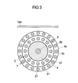
- FIG. 3 shows a second embodiment of an electrical conductor for forming a capacitive sensor element.
- FIG. 4 shows a capacitive sensor element together with an assigned evaluation unit.
- FIG. 5 shows a third embodiment of an electrical conductor for forming a capacitive sensor element.
- FIG. 6 shows a schematic cross-section through a motor vehicle steering wheel with capacitive sensor element.
- FIG. 1 shows a motor vehicle seat 100 , which comprises a seat cushion 101 provided on a seat underframe as well as a backrest 106 being hinged (foldable) to a seat underframe such that a vehicle occupant I being located on the vehicle seat sits on the one hand on the seat cushion 101 and can be supported on the other hand by its back on the backrest 106 .
- the cushion 101 comprises for instance an upholstery 102 and a cover 104 , wherein hereby in the area of the seat surface of the seat cushion 101 a sensor mat 103 is arranged between the seat upholstery 102 and the cover 104 , wherein said sensor mat comprises at least one capacitive sensor element.
- a first electrical conducting element subsequently simply designated as first conductor element or as first electrical conductor, can be integrated into the sensor mat, wherein said first element forms an electrode of the capacitive sensor element and is being connected to an evaluation unit 6 , in order to be able to determine the capacity between the sensor mat 103 , more specific the at least one capacitive sensor element (electrode) being arranged on the sensor mat 103 , and a reference potential of the motor vehicle containing the vehicle seat.
- the evaluation unit 6 can in turn interact with a control device (not shown), which depending on the occupation of the vehicle seat with an occupant I and optionally depending on the size and the weight of the occupant as well as depending on the fact if the corresponding occupant sits directly on the vehicle seat 100 or if it is a toddler being housed by a children seat, activates or deactivates assigned safety devices of the vehicle seat, as for instance an airbag.
- a control device not shown
- the capacity between the sensor mat 103 and the reference potential is essentially determined by the combination of two capacities, namely the capacity C SI between the sensor mat 103 and the vehicle occupant I as well as the capacity C IN between the vehicle occupant and the reference potential.
- the capacity C SI between the sensor mat 103 and the vehicle occupant I as well as the capacity C IN between the vehicle occupant and the reference potential.
- suitable possibilities to couple the vehicle occupant I to the reference potential such that a particularly exact determination of the occupation of the vehicle seat 100 is possible as well as regarding the (capacity) measurement it is pointed for further details to the U.S. Pat. No. 6,563,231 B1.
- the design of the electrical conductor is in particular important, which forms the electrode of the sensor mat 103 , to which the capacity measurements required for detecting the seat occupation are related to.
- a first electrical conductor being arranged as a part of a sensor mat 103 below a seat cover 104 , wherein said conductor forms a capacitive sensor element or an electrode of a sensor mat, is provided as an outer conductor, which houses an electrical reference conductor element serving for defining or forming an electrical reference potential (subsequently simply designated as reference conductor 3 ) as inner conductor and which encloses it (completely) cover like.
- the reference conductor 3 as inner conductor continues thereby longitudinally extending (vertical to the plane of FIG. 2 ) and the first conductor 1 forming the capacitive sensor element continues (also vertical to the plane of the FIG. 2 ) along the reference conductor 3 .
- the first conductor 1 as outer conductor and the reference conductor 3 as inner conductor form according to the configuration of FIG. 2 an arrangement of the type according to a shielded conductor, for instance a coaxial cable, with the inner conductor as cable core and the outer conductor as outer cover.
- the reference conductor 3 which serves as a (seat integrated) reference potential element, which (for instance instead of the vehicle floor frequently provided therefore) forms/defines a reference potential (for capacity determination), can thereby at present be provided simultaneously as a (being electrically operable by current) heating conductor (for heating the seat 100 or the seat cushion 101 ).
- the sensor mat 103 forms then at the same time a heating mat.
- any straight line g (as indicated by a dotted line in FIG. 2 ), which extends in the cross-sectional plane of the sensor assembly, which intersects the first conductor 1 and the reference conductor 3 , can be brought independent on the spatial orientation of the straight line g in the cross-sectional plane by parallel displacement in the cross-sectional plane into a position, in which it forms a curve secant s of the first conductor 1 (thus connects two points of the first conductor 1 being distanced from each other in the cross-sectional plane with each other) without intersecting the reference conductor 3 .
- the reference conductor 3 is surrounded by an insulator or dielectric 4 , which extends between the reference conductor 3 as inner conductor and the first conductor 1 as outer conductor and which in the embodiment is surrounded by a (moisture tight) protective cover 5 b towards the outer first conductor 1 .
- the reference conductor 3 serves as heating conductor at the same time to produce heat when under current with electrical current such that hereby for instance the seat surface of a seat cushion can be heated.
- the material of the dielectric 4 is hereby selected such that a sufficient part of the heat produced in the heating conductor 3 (can enter through the dielectric 4 and) is provided for heating the seat cushion 101 .
- the first conductor 1 being provided as cover like outer conductor is adjacent (radially) outwards to the reference conductor 3 and the dielectric 4 , here surrounded by a protective cover 5 b , wherein said first conductor is being formed by a conductive material at present in form of a cable network 11 or alternatively in form of an electrically conducting film or a conductor path.
- a (moisture tight) protective cover 5 a can also be provided on the outside of the outer first conductor 1 .
- the capacitive sensor element (first conductor 1 ) and the occupant I or its body part facing the sensor element form a first condenser (of the capacity C SI ) and the occupant I as well as an element defining the reference potential (here the reference conductor 3 ) form a second condenser (of the capacity C IN ), if an occupant I is present on the seat 100 of FIG. 1 .
- the two condensers are approximately connected in series.
- the evaluation unit 6 is connected to the sensor assembly 1 , 3 and can detect a measured value (for instance a measured current) or a change of a measured value as consequence of a capacitive coupling caused by a vehicle occupant I between the capacitive sensor element (first conductor 1 ) and the reference potential (defined by the reference conductor 3 ).
- a measured value for instance a measured current
- a change of a measured value as consequence of a capacitive coupling caused by a vehicle occupant I between the capacitive sensor element (first conductor 1 ) and the reference potential (defined by the reference conductor 3 ).
- the strength, a frequency, the amplitude and/or the phase of a measured current can be determined.
- the dielectric 4 surrounding the reference conductor 3 as inner conductor is on one hand sufficiently rigid designed such that it cannot be deformed by forces or pressures occurring during normal operation of the sensor assembly. Forces and pressures occurring under normal operation are thereby in particular such which are caused by a vehicle occupant I sitting on the vehicle seat 100 , compare FIG. 1 .
- the dielectric 4 provides that the (radial) distance between the first conductor 1 as outer conductor and the reference conductor 3 as inner conductor remains always constant independent on the occupation of the corresponding vehicle seat such that force or pressure impact does not substantially influence the resulting capacity (by using the outer conductor 1 as capacitive sensor element).
- the material of the dielectric 4 can be for instance selected such that it is not being deformed by the action of the weight of the children seat including a toddler being located therein, but a substantial deformation occurs only at a force or pressure threshold, which is above the weight of a children seat with toddler and for instance corresponds to the weight of a small female occupant (so called 5% woman).
- the sensor assembly can thus also be designed by suitable selection of the dielectric 4 additionally as a pressure sensitive sensor (pressure sensor) in order to gain herewith additional information about a vehicle occupant being located on the assigned vehicle seat 100 .
- a pressure sensitive sensor pressure sensor
- a location depending or direction depending pressure sensitivity of the sensor assembly can be achieved by using different (insulating) materials for different areas 41 , 42 , 43 , 44 of the dielectric 4 .
- areas 41 , 42 , 43 , 44 materials with comparatively large compressibility (comparatively large compressibility or small compression module) as well as materials with comparatively low compressibility (for instance small compressibility or large compression module) are used, it can be achieved that distance changes between the first conductor 1 as external conductor and the reference conductor 3 as internal conductor depend on the location and/or the direction of a force acting on the sensor assembly.
- a suitable selected reaction delay allows in particular a phase wise measurement, wherein at first (before the delayed deformation of the dielectric as a consequence of a force impact) purely capacitive coupling changes—as consequence of an occupation of the seat—are detected and subsequently (during or after deformation of the dielectric) the influence of a deformation of the dielectric onto the capacitive coupling is detected, whereby additional data for detecting the seat occupation as well as differentiation between different large/heavy vehicle occupant is provided.
- the material of the dielectric 4 can be selected such that it extends or contracts at temperature changes, thus by a change of the surrounding temperature and/or by a change of the temperature produced by the reference/heating conductor 3 when in operation—depending if a temperature increase or a temperature decrease takes place—such that the distances between the components of the sensor assembly, in particular between the outer, first conductor 1 serving as capacitive sensor element and the reference/heating conductor 3 changes.
- the effects connected herewith onto the capacity detected at predetermined conditions (occupation or non-occupation of the seat as well as optionally constitution of an occupant occupying the seat) allow a conclusion about the surrounding temperature or—when operating the reference conductor 3 as heating conductor—on the temperature produced by the heating conductor.
- devices of a motor vehicle as for instance the heating device itself or a climate device, can be controlled or regulated and on the other hand temperature influences onto the sensor assembly can sufficiently be considered.
- FIG. 3 shows a modification of the sensor assembly of FIG. 2 according to which an additional second conductor 2 extends between the first conductor 1 as outer conductor and the reference conductor 3 as inner conductor, wherein said second conductor is here (also) formed as cable network 21 and which surrounds the reference conductor 3 and the dielectric 4 cover like.
- the first conductor 1 in form of an outer conductor serving as capacitive sensor element can be shielded against the reference conductor 3 in form of an inner conductor such that distance changes between the first conductor 1 and the reference conductor 3 have no substantial back impact on the resulting capacity.
- the shield formed by the second conductor 2 can be thereby formed as a so called potential controlled shield (“driven shield”).
- a further (optionally moisture tight) protective cover 5 c can continue between the first conductor 1 and the second conductor 2 .
- one or multiple protective covers can be provided in practice depending on the need of the three protective covers 5 a , 5 b , 5 c shown in FIG. 3 .
- the sensor assembly according to FIG. 3 is formed according to the type of a triaxial cable with the reference conductor 3 as cable core, the first conductor 1 as outer cover and the second conductor 2 as middle cover, which encloses the reference cover 3 /cable core and which in turn is being enclosed by the outer cover formed by the first conductor 1 .
- FIG. 4 shows a sensor assembly 1 , 3 of the type illustrated in cross-section in FIG. 2 or 3 as part of a sensor mat 103 together with a downstream arranged evaluation unit 6 for evaluating exit signals produced by the sensor assembly 1 , 3 .
- the evaluation unit 6 can thereby serve on one hand to detect in a simple manner the capacity of the sensor mat 103 in relation to the reference potential, which is determined by occupation of the corresponding vehicle seat 100 with a vehicle occupant I, compare FIG. 1 , by the connection (for instance connection in series) of the capacity C SI between the sensor mat 103 and the vehicle occupant I as well as the capacity C IN between the vehicle occupant I and the reference potential.
- the first conductor 1 (outer conductor) of the sensor assembly as capacitive sensor element is provided with an alternating current, for instance a sinus signal of a defined frequency of about 120 kHz.
- an energy supply device 65 is assigned to the evaluation unit 6 ; and in a signal generating device 61 a (sinus like) alternating current is generated with a defined phase and amplitude and is directed to the sensor mat 103 or the sensor assembly 1 , 3 (more precise to the at least one outer conductor 1 forming a capacitive sensor element).
- the generation of said sinus signal can be controlled by a microprocessor 60 of the evaluation unit 6 .
- a measuring device 62 which is integrated into an electrical connecting line connected to the sensor assembly 1 , 3 and which is located in the embodiment between the signal generating device 61 and the sensor assembly 1 , 3 or the sensor mat 103 , the actual provided alternating current is measured and the measured result is provided to the microprocessor 60 of the evaluation unit 6 .
- the microprocessor 60 of the evaluation unit 6 By comparing parameters of the alternating current generated in the signal generating device 61 , as for instance amplitude and phase, with the corresponding parameters measured actually at the measuring device 62 , thus for instance amplitude and phase, deviations of said parameters effected by the sensor mat 103 or sensor assembly 1 , 3 and their capacitive interaction with the surrounding (for instance with the vehicle occupant) can be determined.
- the active current part (thus the phase like part or reality part of the alternating current forming the basis of the alternating voltage), in particular as basis for the determination of a phase shift, and/or the reactive current part (imaginary part of the alternating current) and/or the quadrature part or effective value of the current, in particular as basis for determining the amplitude, are detected.
- the capacities of the sensor assembly in respect to a reference potential can be concluded in particular from the amplitude deviations and from deviations of the phase it can be concluded to possible leakage current, which are caused by humidity or moisture in the seat.
- the information obtained about the seat occupation can be transferred via an interface 68 to a control device in order to control dependent thereof vehicle systems, in particular occupant safety systems as for instance an airbag system.
- FIG. 5 shows a capacitive sensor assembly, which comprises a capacitive sensor element 1 in form of an outer conductor, which surrounds a (optionally serving as a heating conductor) reference conductor 3 as inner conductor, wherein a dielectric extends between the reference conductor 3 as inner conductor and the capacitive sensor element 1 as outer conductor in cross-section.
- the arrangement shown in FIG. 5 in particular its first conductor 1 as outer conductor as well as the reference conductor 3 and the dielectric 4 , extends thereby vertical to the plane of FIG. 5 .
- the arrangement corresponds in so far to the principle construction of the arrangement of
- the arrangement corresponds in so far to the principle design of the arrangement of FIG. 2 with the difference that at present it is a system constructed of layers, that—according to the type of a flat conductor—consists of a multitude of layers being arranged on each other (for instance laminated) as being subsequently explained in more detail.
- FIG. 5 it is thereby furthermore indicated that the arrangement of the outer, first conductor 1 , the inner reference conductor 3 as well as the dielectric 4 being there between can be surrounded outside by a further dielectric 4 ′, to which again an electrical conductive element 1 ′ can be adjacent and so on.
- electrical conductor 1 , 1 ′, . . . can follow each other outwards, wherein said conductors are being in each case separated from each other by a suitable insulating layer.
- Interfaces between the layers arranged on each other (laminated on each other) are indicated by a dotted line in FIG. 5 , which form the sensor assembly of FIG. 5 .
- FIG. 6 shows finally a cross section of a steering wheel 200 in the area of the steering wheel rim with a capacitive sensor assembly 203 being arranged thereon.
- the steering wheel 200 comprises in the area of the rim a skeleton 201 surrounded by a cover 202 , for instance steering wheel foam, and with a cover 204 defining the outer surface of the steering wheel rim, for instance made of leather.
- the capacitive sensor assembly 203 is arranged, which comprises a multitude of arrangements 1 , 3 of the type shown in FIG. 2 or 3 or 5 , thus in each case a capacitive element formed as an outer conductor and a reference conductor/heating conductor as inner conductor.
Landscapes
- Engineering & Computer Science (AREA)
- Aviation & Aerospace Engineering (AREA)
- Transportation (AREA)
- Mechanical Engineering (AREA)
- Seats For Vehicles (AREA)
- Chair Legs, Seat Parts, And Backrests (AREA)
- Steering Controls (AREA)
Abstract
Description
Claims (18)
Applications Claiming Priority (4)
| Application Number | Priority Date | Filing Date | Title |
|---|---|---|---|
| DE102009055426 | 2009-12-30 | ||
| DE102009055426.2 | 2009-12-30 | ||
| DE102009055426A DE102009055426A1 (en) | 2009-12-30 | 2009-12-30 | Capacitive sensor module |
| PCT/EP2010/070938 WO2011080324A1 (en) | 2009-12-30 | 2010-12-30 | Capacitive sensor assembly |
Publications (2)
| Publication Number | Publication Date |
|---|---|
| US20120306512A1 US20120306512A1 (en) | 2012-12-06 |
| US8970232B2 true US8970232B2 (en) | 2015-03-03 |
Family
ID=43768998
Family Applications (1)
| Application Number | Title | Priority Date | Filing Date |
|---|---|---|---|
| US13/520,137 Expired - Fee Related US8970232B2 (en) | 2009-12-30 | 2010-12-30 | Capacitive sensor assembly |
Country Status (6)
| Country | Link |
|---|---|
| US (1) | US8970232B2 (en) |
| EP (1) | EP2520023B1 (en) |
| JP (1) | JP2013516347A (en) |
| CN (1) | CN102484474B (en) |
| DE (1) | DE102009055426A1 (en) |
| WO (1) | WO2011080324A1 (en) |
Cited By (11)
| Publication number | Priority date | Publication date | Assignee | Title |
|---|---|---|---|---|
| US20150336601A1 (en) * | 2014-05-22 | 2015-11-26 | Tk Holdings Inc. | Systems and methods for shielding a hand sensor system in a steering wheel |
| US9266454B2 (en) | 2013-05-15 | 2016-02-23 | Gentherm Canada Ltd | Conductive heater having sensing capabilities |
| US9701232B2 (en) | 2013-10-11 | 2017-07-11 | Gentherm Gmbh | Occupancy sensing with heating devices |
| CN107064721A (en) * | 2015-11-15 | 2017-08-18 | 博泽(班贝格)汽车零部件有限公司 | Method for the sensor cluster of the electric capacity that runs motor vehicle |
| US20180216969A1 (en) * | 2017-01-27 | 2018-08-02 | Hitachi Metals, Ltd. | Composite detection sensor and sensor cable |
| US10056702B2 (en) | 2015-11-04 | 2018-08-21 | Gentherm, Inc. | Crimp connection for mesh shielding material used in steering wheel with capacitive sensing |
| US10114513B2 (en) | 2014-06-02 | 2018-10-30 | Joyson Safety Systems Acquisition Llc | Systems and methods for printing sensor circuits on a sensor mat for a steering wheel |
| US20180319290A1 (en) * | 2015-10-30 | 2018-11-08 | Gentherm Gmbh | Device for temperature control of certain areas and for recognizing occupation thereof by persons and/or objects, and seating and/or reclining apparatus including such a device |
| US10336361B2 (en) | 2016-04-04 | 2019-07-02 | Joyson Safety Systems Acquisition Llc | Vehicle accessory control circuit |
| US20190305776A1 (en) * | 2016-09-21 | 2019-10-03 | Brose Fahrzeugteile GmbH & Co. Kommanditgesellscha ft, Bamberg | Capacitive sensor electrode, method for producing a capacitive sensor electrode, and capacitive sensor |
| US10563447B2 (en) | 2011-12-21 | 2020-02-18 | Brose Fahrzeugteile Gmbh & Co. Kg, Hallstadt | Control system |
Families Citing this family (16)
| Publication number | Priority date | Publication date | Assignee | Title |
|---|---|---|---|---|
| DE102011008277B4 (en) * | 2011-01-11 | 2017-01-12 | Brose Fahrzeugteile Gmbh & Co. Kommanditgesellschaft, Bamberg | Sensor unit for contactless actuation of a vehicle door |
| JP5871422B2 (en) | 2011-06-22 | 2016-03-01 | ティーケー ホールディングス インク.Tk Holdings Inc. | Sensor system for a vehicle steering wheel |
| WO2013023629A1 (en) * | 2011-08-17 | 2013-02-21 | Huf Hülsbeck & Fürst Gmbh & Co. Kg | Apparatus for operating a door or hatch on a vehicle |
| DE102011084903A1 (en) | 2011-10-20 | 2013-04-25 | TAKATA Aktiengesellschaft | Sensor systems for a motor vehicle |
| DE102012000572A1 (en) * | 2012-01-16 | 2013-07-18 | Trw Automotive Safety Systems Gmbh | Steering wheel for motor vehicle, has touch sensor that is activated by user for operation by manual touch on sensor surface, and generates electrical signal around control unit for activating function element |
| DE102013220240A1 (en) * | 2013-10-08 | 2015-04-09 | Bayerische Motoren Werke Aktiengesellschaft | In-vehicle occupant presence system, central locking system, method for checking occupant presence in the vehicle, and method for automatically actuating door locks |
| DE102015216095B4 (en) * | 2015-08-24 | 2023-08-03 | Joyson Safety Systems Germany Gmbh | Method and device for determining a system status of an electronic measuring system |
| EP3509898A4 (en) * | 2016-09-12 | 2020-03-11 | Suzhou Swandoo Children's Articles Co., Ltd | Occupancy sensing for a child transportation system |
| JP6449832B2 (en) * | 2016-10-28 | 2019-01-09 | 本田技研工業株式会社 | Steering wheel unit |
| JP6339156B2 (en) * | 2016-10-28 | 2018-06-06 | 本田技研工業株式会社 | Steering unit |
| DE102016226101A1 (en) * | 2016-12-22 | 2018-06-28 | Takata AG | Steering wheel for a motor vehicle and method for producing a steering wheel |
| DE102017107971B4 (en) * | 2017-04-12 | 2019-08-01 | Lisa Dräxlmaier GmbH | ARMUFLAGE FOR AN INTERIOR OF A MOTOR VEHICLE |
| DE102017212460B4 (en) | 2017-07-20 | 2019-07-11 | Leoni Kabel Gmbh | SENSOR LINE |
| DE102017120375A1 (en) * | 2017-09-05 | 2019-03-07 | Huf Hülsbeck & Fürst Gmbh & Co. Kg | Sensor device for the capacitive detection of a user action in a vehicle |
| DE102018113879A1 (en) * | 2018-06-11 | 2019-12-12 | Trw Automotive Safety Systems Gmbh | Method for detecting a touch of a hand-operated steering device, in particular a vehicle steering wheel, and device for carrying out the method |
| CN111380570B (en) * | 2018-12-28 | 2022-05-03 | 霍尼韦尔国际公司 | Devices, systems, and methods for improved sensor wire retention |
Citations (32)
| Publication number | Priority date | Publication date | Assignee | Title |
|---|---|---|---|---|
| US3626287A (en) | 1969-02-10 | 1971-12-07 | C G I Corp | System for responding to changes in capacitance of a sensing capacitor |
| JPS58213313A (en) | 1982-06-04 | 1983-12-12 | Matsushita Electric Ind Co Ltd | Warmer for use with dc power supply |
| JPS63305074A (en) | 1987-06-03 | 1988-12-13 | Aisin Seiki Co Ltd | Operating handle heating apparatus |
| JPS6451564U (en) | 1987-09-26 | 1989-03-30 | ||
| JPH0286085A (en) | 1988-03-31 | 1990-03-27 | Toshiba Corp | Electric heater |
| JPH05291924A (en) | 1992-04-15 | 1993-11-05 | Matsushita Electric Works Ltd | Human body sensor |
| WO1995013204A1 (en) | 1993-11-10 | 1995-05-18 | Robert Bosch Gmbh | Electronic device for controlling a seat-heating system |
| WO1998022836A1 (en) | 1996-11-01 | 1998-05-28 | Scandmec Ab | Device for presence detection |
| DE19907199A1 (en) | 1998-02-20 | 1999-11-18 | Trw Vehicle Safety Systems | Device for determination of the characteristics of a person occupying a vehicle seat by use of capacitor sensors |
| WO2001014171A1 (en) | 1999-08-24 | 2001-03-01 | Harald Philipp | Occupancy sensor |
| US20010045733A1 (en) | 2000-05-26 | 2001-11-29 | Stanley James Gregory | Occupant sensor |
| WO2002006083A1 (en) | 2000-07-17 | 2002-01-24 | Kongsberg Automotive Ab | Vehicle seat heating arrangement |
| DE10048956C1 (en) | 2000-10-04 | 2002-05-02 | Autoliv Dev | Motor vehicle steering wheel, has conducting surface on steering wheel in common with driver's hand contact surface to form capacitor with wheel cover forming dielectric |
| US20030005775A1 (en) | 2001-07-09 | 2003-01-09 | Nartron Corporation | Compressible capacitance sensor for determining the presence of an object |
| US6517106B1 (en) | 1998-12-30 | 2003-02-11 | Automotive Systems Laboratory, Inc. | Occupant detection system |
| US20030056600A1 (en) | 2001-07-09 | 2003-03-27 | Nartron Corporation | Anti-entrapment system |
| DE20309877U1 (en) | 2003-06-26 | 2003-10-30 | Trw Automotive Safety Sys Gmbh | Vehicle Security System |
| WO2004022409A2 (en) | 2002-09-06 | 2004-03-18 | Continental Teves Ag & Co.Ohg | Steering wheel for motor vehicles with free hand recognition |
| DE10358791A1 (en) | 2003-12-12 | 2005-08-04 | Carl Freudenberg Kg | Combined sensor and heating element |
| DE10358793A1 (en) | 2003-12-12 | 2005-08-04 | Carl Freudenberg Kg | Combined sensor and heating element |
| FR2868999A1 (en) | 2004-04-20 | 2005-10-21 | Faurecia Sieges Automobile | Motor vehicle seat heating device, has heater mats including linen layers on which threads forming electrical resistance are sewn, and electrical conductor shielding sewn above and below layers so as to coat threads |
| US20060022682A1 (en) | 2004-07-15 | 2006-02-02 | Fujikura Ltd. | Electrical capacitance proximity sensor |
| US7132642B2 (en) | 2001-07-09 | 2006-11-07 | Nartron Corporation | Anti-entrapment systems for preventing objects from being entrapped by translating devices |
| DE102006008919A1 (en) | 2005-02-23 | 2006-12-21 | Takata-Petri Ag | Seat belt system for motor vehicle has measuring device is positioned with respect to belt in such a manner, that it is arranged in belt proceeding direction behind belt retractor |
| US20070089527A1 (en) | 2001-07-09 | 2007-04-26 | Nartron Corporation | Anti-entrapment system |
| JP2007123202A (en) | 2005-10-31 | 2007-05-17 | Asmo Co Ltd | Cord switch and detection device using the same |
| US20070200721A1 (en) | 2006-02-10 | 2007-08-30 | Tk Holdings Inc. | Occupant classification system |
| DE102006031207B3 (en) | 2006-07-03 | 2007-11-22 | Takata-Petri Ag | Sensor system for steering wheel of motor vehicle, has sensor unit arranged at steering wheel rim for detecting effect of acceleration on rim, where output signal is delivered by sensor unit, when effect of acceleration exceeds preset value |
| US20080011732A1 (en) | 2006-07-11 | 2008-01-17 | Denso Corporation | Passenger seat having occupant detector for automotive vehicle |
| US7407029B2 (en) * | 1992-05-05 | 2008-08-05 | Automotive Technologies International, Inc. | Weight measuring systems and methods for vehicles |
| DE102007022463A1 (en) | 2007-05-09 | 2008-11-13 | Takata-Petri Ag | measuring system |
| DE102007024141A1 (en) | 2007-05-23 | 2008-11-27 | Takata-Petri Ag | Sensor system for steering wheel and component, particularly seat or steering wheel rim of motor vehicle, has sensor unit arranged in or at component for detection of impact of compressive force or torsion force on component |
Family Cites Families (2)
| Publication number | Priority date | Publication date | Assignee | Title |
|---|---|---|---|---|
| EP1573695A4 (en) * | 2002-05-21 | 2008-08-06 | Automotive Systems Lab | Occupant detection system |
| JP4116409B2 (en) * | 2002-12-02 | 2008-07-09 | 日星電気株式会社 | Capacitive sensor |
-
2009
- 2009-12-30 DE DE102009055426A patent/DE102009055426A1/en not_active Ceased
-
2010
- 2010-12-30 US US13/520,137 patent/US8970232B2/en not_active Expired - Fee Related
- 2010-12-30 JP JP2012546452A patent/JP2013516347A/en active Pending
- 2010-12-30 CN CN201080040635.4A patent/CN102484474B/en not_active Expired - Fee Related
- 2010-12-30 WO PCT/EP2010/070938 patent/WO2011080324A1/en active Application Filing
- 2010-12-30 EP EP10803461.2A patent/EP2520023B1/en active Active
Patent Citations (52)
| Publication number | Priority date | Publication date | Assignee | Title |
|---|---|---|---|---|
| US3626287A (en) | 1969-02-10 | 1971-12-07 | C G I Corp | System for responding to changes in capacitance of a sensing capacitor |
| JPS58213313A (en) | 1982-06-04 | 1983-12-12 | Matsushita Electric Ind Co Ltd | Warmer for use with dc power supply |
| JPS63305074A (en) | 1987-06-03 | 1988-12-13 | Aisin Seiki Co Ltd | Operating handle heating apparatus |
| JPS6451564U (en) | 1987-09-26 | 1989-03-30 | ||
| JPH0286085A (en) | 1988-03-31 | 1990-03-27 | Toshiba Corp | Electric heater |
| JPH05291924A (en) | 1992-04-15 | 1993-11-05 | Matsushita Electric Works Ltd | Human body sensor |
| US7407029B2 (en) * | 1992-05-05 | 2008-08-05 | Automotive Technologies International, Inc. | Weight measuring systems and methods for vehicles |
| WO1995013204A1 (en) | 1993-11-10 | 1995-05-18 | Robert Bosch Gmbh | Electronic device for controlling a seat-heating system |
| WO1998022836A1 (en) | 1996-11-01 | 1998-05-28 | Scandmec Ab | Device for presence detection |
| DE19907199A1 (en) | 1998-02-20 | 1999-11-18 | Trw Vehicle Safety Systems | Device for determination of the characteristics of a person occupying a vehicle seat by use of capacitor sensors |
| US6158768A (en) | 1998-02-20 | 2000-12-12 | Trw Vehicle Safety Systems Inc. /Trw Inc. | Apparatus and method for discerning certain occupant characteristics using a plurality of capacitive sensors |
| US6517106B1 (en) | 1998-12-30 | 2003-02-11 | Automotive Systems Laboratory, Inc. | Occupant detection system |
| US6563231B1 (en) | 1998-12-30 | 2003-05-13 | Automotive Systems Laboratory, Inc. | Occupant sensor |
| WO2001014171A1 (en) | 1999-08-24 | 2001-03-01 | Harald Philipp | Occupancy sensor |
| EP1301800B1 (en) | 2000-05-26 | 2006-08-09 | Automotive Systems Laboratory Inc. | Occupant sensor |
| US20040113634A1 (en) | 2000-05-26 | 2004-06-17 | Automotive Systems Laboratory, Inc. | Occupant sensor |
| US20010045733A1 (en) | 2000-05-26 | 2001-11-29 | Stanley James Gregory | Occupant sensor |
| JP2003535341A (en) | 2000-05-26 | 2003-11-25 | オートモーティブ システムズ ラボラトリー インコーポレーテッド | Occupant sensor |
| US6703845B2 (en) | 2000-05-26 | 2004-03-09 | Automotive Systems Laboratory, Inc. | Occupant sensor |
| WO2002006083A1 (en) | 2000-07-17 | 2002-01-24 | Kongsberg Automotive Ab | Vehicle seat heating arrangement |
| DE10048956C1 (en) | 2000-10-04 | 2002-05-02 | Autoliv Dev | Motor vehicle steering wheel, has conducting surface on steering wheel in common with driver's hand contact surface to form capacitor with wheel cover forming dielectric |
| US20030056600A1 (en) | 2001-07-09 | 2003-03-27 | Nartron Corporation | Anti-entrapment system |
| JP2005502859A (en) | 2001-07-09 | 2005-01-27 | ナートロン コーポレーション | Compressible capacitive sensor for object presence determination |
| US20070089527A1 (en) | 2001-07-09 | 2007-04-26 | Nartron Corporation | Anti-entrapment system |
| EP1933461A1 (en) | 2001-07-09 | 2008-06-18 | Nartron Corporation | Compressible capacitance sensor for determining the presence of an object |
| US7293467B2 (en) | 2001-07-09 | 2007-11-13 | Nartron Corporation | Anti-entrapment system |
| US20030005775A1 (en) | 2001-07-09 | 2003-01-09 | Nartron Corporation | Compressible capacitance sensor for determining the presence of an object |
| US7132642B2 (en) | 2001-07-09 | 2006-11-07 | Nartron Corporation | Anti-entrapment systems for preventing objects from being entrapped by translating devices |
| WO2004022409A2 (en) | 2002-09-06 | 2004-03-18 | Continental Teves Ag & Co.Ohg | Steering wheel for motor vehicles with free hand recognition |
| US20050242965A1 (en) | 2002-09-06 | 2005-11-03 | Peter Rieth | Steering handle for motor vehicles and method for recording a physical parameter on a steering handle |
| JP2006501388A (en) | 2002-09-30 | 2006-01-12 | ナートロン コーポレイション | Anti-pinch system |
| EP1491409A1 (en) | 2003-06-26 | 2004-12-29 | TRW Automotive Safety Systems GmbH | Vehicle safety system |
| US20040267422A1 (en) | 2003-06-26 | 2004-12-30 | Trw Automotive Safety Systems Gmbh | Vehicle safety system |
| DE20309877U1 (en) | 2003-06-26 | 2003-10-30 | Trw Automotive Safety Sys Gmbh | Vehicle Security System |
| DE10358791A1 (en) | 2003-12-12 | 2005-08-04 | Carl Freudenberg Kg | Combined sensor and heating element |
| DE10358793A1 (en) | 2003-12-12 | 2005-08-04 | Carl Freudenberg Kg | Combined sensor and heating element |
| US20070290532A1 (en) | 2003-12-12 | 2007-12-20 | Carl Freudenberg Kg | Combined Sensor and Heating Element |
| US20070215601A1 (en) | 2003-12-12 | 2007-09-20 | Thorsten Frank | Combined sensor and heating element |
| FR2868999A1 (en) | 2004-04-20 | 2005-10-21 | Faurecia Sieges Automobile | Motor vehicle seat heating device, has heater mats including linen layers on which threads forming electrical resistance are sewn, and electrical conductor shielding sewn above and below layers so as to coat threads |
| US20060022682A1 (en) | 2004-07-15 | 2006-02-02 | Fujikura Ltd. | Electrical capacitance proximity sensor |
| DE102006008919A1 (en) | 2005-02-23 | 2006-12-21 | Takata-Petri Ag | Seat belt system for motor vehicle has measuring device is positioned with respect to belt in such a manner, that it is arranged in belt proceeding direction behind belt retractor |
| US20070117445A1 (en) | 2005-10-31 | 2007-05-24 | Hitachi Cable, Ltd. | Cord switch and detecting apparatus using the same |
| JP2007123202A (en) | 2005-10-31 | 2007-05-17 | Asmo Co Ltd | Cord switch and detection device using the same |
| US20070200721A1 (en) | 2006-02-10 | 2007-08-30 | Tk Holdings Inc. | Occupant classification system |
| DE102006031207B3 (en) | 2006-07-03 | 2007-11-22 | Takata-Petri Ag | Sensor system for steering wheel of motor vehicle, has sensor unit arranged at steering wheel rim for detecting effect of acceleration on rim, where output signal is delivered by sensor unit, when effect of acceleration exceeds preset value |
| US20090199676A1 (en) | 2006-07-03 | 2009-08-13 | Takata-Petri Ag | Sensor System For A Steering Wheel Of A Motor Vehicle |
| JP2008018789A (en) | 2006-07-11 | 2008-01-31 | Denso Corp | Vehicular seat device |
| CN101108595A (en) | 2006-07-11 | 2008-01-23 | 株式会社电装 | Passenger seat having occupant detector for automotive vehicle |
| US20080011732A1 (en) | 2006-07-11 | 2008-01-17 | Denso Corporation | Passenger seat having occupant detector for automotive vehicle |
| DE102007022463A1 (en) | 2007-05-09 | 2008-11-13 | Takata-Petri Ag | measuring system |
| US20100057304A1 (en) | 2007-05-09 | 2010-03-04 | Takata-Petri Ag | Measuring system and measuring method for detecting at least one frequency independent electrical quantity |
| DE102007024141A1 (en) | 2007-05-23 | 2008-11-27 | Takata-Petri Ag | Sensor system for steering wheel and component, particularly seat or steering wheel rim of motor vehicle, has sensor unit arranged in or at component for detection of impact of compressive force or torsion force on component |
Non-Patent Citations (7)
| Title |
|---|
| English translation of Notification of the First Office Action issued in counterpart Chinese Application No. 201080040635.4, dated Jun. 5, 2013 (10 pages). |
| English translation of Notification of the First Office Action issued in counterpart Chinese Application No. 201080040707.5 dated Apr. 28, 2013 (9 pages). |
| English translation of the International Preliminary Report on Patentability (Chapter I or Chapter II of the Patent Cooperation Treaty) from the International Bureau of WIPO for International Application No. PCT/EP2010/070938 dated Jul. 19, 2012, 9 pages. |
| Japanese Office Action dated Oct. 29, 2014 for JP 2012-546452 and English translation of the same. (5 pages). |
| Office Action issued in corresponding Chinese Application No. 201080040635.4 dated Jul. 25, 2014 and English translation of the same (22 pages). |
| Office Action issued in corresponding Japanese Application No. 2012-546451 dated Jan. 30, 2014 and English translation of the same (11 pages). |
| Office Action issued in corresponding Japanese Application No. 2012-546452 dated Jun. 26, 2014 and English translation of the same (7 pages). |
Cited By (21)
| Publication number | Priority date | Publication date | Assignee | Title |
|---|---|---|---|---|
| US10563447B2 (en) | 2011-12-21 | 2020-02-18 | Brose Fahrzeugteile Gmbh & Co. Kg, Hallstadt | Control system |
| US11384589B2 (en) | 2011-12-21 | 2022-07-12 | Brose Fahrzeugteile Gmbh & Co. Kg, Hallstadt | Control system |
| US9266454B2 (en) | 2013-05-15 | 2016-02-23 | Gentherm Canada Ltd | Conductive heater having sensing capabilities |
| US10075999B2 (en) | 2013-05-15 | 2018-09-11 | Gentherm Gmbh | Conductive heater having sensing capabilities |
| US9701232B2 (en) | 2013-10-11 | 2017-07-11 | Gentherm Gmbh | Occupancy sensing with heating devices |
| US10076982B2 (en) | 2013-10-11 | 2018-09-18 | Gentherm Gmbh | Occupancy sensing with heating devices |
| US10124823B2 (en) * | 2014-05-22 | 2018-11-13 | Joyson Safety Systems Acquisition Llc | Systems and methods for shielding a hand sensor system in a steering wheel |
| US20150336601A1 (en) * | 2014-05-22 | 2015-11-26 | Tk Holdings Inc. | Systems and methods for shielding a hand sensor system in a steering wheel |
| US11299191B2 (en) | 2014-05-22 | 2022-04-12 | Joyson Safety Systems Acquisition Llc | Systems and methods for shielding a hand sensor system in a steering wheel |
| US11599226B2 (en) | 2014-06-02 | 2023-03-07 | Joyson Safety Systems Acquisition Llc | Systems and methods for printing sensor circuits on a sensor mat for a steering wheel |
| US10114513B2 (en) | 2014-06-02 | 2018-10-30 | Joyson Safety Systems Acquisition Llc | Systems and methods for printing sensor circuits on a sensor mat for a steering wheel |
| US10698544B2 (en) | 2014-06-02 | 2020-06-30 | Joyson Safety Systems Acquisitions LLC | Systems and methods for printing sensor circuits on a sensor mat for a steering wheel |
| US20180319290A1 (en) * | 2015-10-30 | 2018-11-08 | Gentherm Gmbh | Device for temperature control of certain areas and for recognizing occupation thereof by persons and/or objects, and seating and/or reclining apparatus including such a device |
| US10056702B2 (en) | 2015-11-04 | 2018-08-21 | Gentherm, Inc. | Crimp connection for mesh shielding material used in steering wheel with capacitive sensing |
| US10355376B2 (en) | 2015-11-04 | 2019-07-16 | Gentherm, Inc. | Crimp connection for mesh shielding material used in steering wheel with capacitive sensing |
| US10429430B2 (en) * | 2015-11-15 | 2019-10-01 | Brose Fahrzeugteile Gmbh & Co. Kg, Bamberg | Method for operating a capacitive sensor arrangement of a motor vehicle |
| CN107064721A (en) * | 2015-11-15 | 2017-08-18 | 博泽(班贝格)汽车零部件有限公司 | Method for the sensor cluster of the electric capacity that runs motor vehicle |
| US10336361B2 (en) | 2016-04-04 | 2019-07-02 | Joyson Safety Systems Acquisition Llc | Vehicle accessory control circuit |
| US20190305776A1 (en) * | 2016-09-21 | 2019-10-03 | Brose Fahrzeugteile GmbH & Co. Kommanditgesellscha ft, Bamberg | Capacitive sensor electrode, method for producing a capacitive sensor electrode, and capacitive sensor |
| US10508933B2 (en) * | 2017-01-27 | 2019-12-17 | Hitachi Metals, Ltd. | Composite detection sensor and sensor cable |
| US20180216969A1 (en) * | 2017-01-27 | 2018-08-02 | Hitachi Metals, Ltd. | Composite detection sensor and sensor cable |
Also Published As
| Publication number | Publication date |
|---|---|
| DE102009055426A1 (en) | 2011-07-07 |
| WO2011080324A1 (en) | 2011-07-07 |
| US20120306512A1 (en) | 2012-12-06 |
| EP2520023B1 (en) | 2014-09-03 |
| JP2013516347A (en) | 2013-05-13 |
| CN102484474A (en) | 2012-05-30 |
| CN102484474B (en) | 2015-03-25 |
| EP2520023A1 (en) | 2012-11-07 |
Similar Documents
| Publication | Publication Date | Title |
|---|---|---|
| US8970232B2 (en) | Capacitive sensor assembly | |
| US8970231B2 (en) | Capacitive sensor assembly | |
| JP2013516347A5 (en) | ||
| JP2013516603A5 (en) | ||
| EP1601555B1 (en) | System for detecting seat occupancy | |
| US8882142B2 (en) | Capacitive occupant detection system | |
| US8237455B2 (en) | Occupant detection system with environmental compensation | |
| JP4229071B2 (en) | Capacitive sensor and occupant detection system | |
| JP4529086B2 (en) | Occupant detection system | |
| EP1795402B1 (en) | Seat occupancy detection device | |
| US6956465B2 (en) | Occupant detection system in a motor vehicle | |
| US9278629B2 (en) | Occupant detection and classification system | |
| CN109689441B (en) | Occupant detection and classification system | |
| JP2008302930A (en) | Multiple sensor vehicle occupant detection system and method for airbag deployment control | |
| JP2016504227A (en) | Crew detection and classification system | |
| JP4564894B2 (en) | Occupant detection system | |
| US20080208414A1 (en) | Control Apparatus For an Occupant Protection Means in a Motor Vehicle | |
| JP3458323B2 (en) | Occupant detection system | |
| CN107709086A (en) | For the capacitance type detector and system used in vehicle interior | |
| EP2698273B1 (en) | Dual electrode occupant detection system and method | |
| JP2005526666A (en) | Occupant detection system | |
| CN108891308A (en) | The face B seat sensor and seat | |
| Becker et al. | TOR (total occupant recognition) system | |
| WO2012135303A1 (en) | Occupant classification system |
Legal Events
| Date | Code | Title | Description |
|---|---|---|---|
| AS | Assignment |
Owner name: TAKATA AG, GERMANY Free format text: ASSIGNMENT OF ASSIGNORS INTEREST;ASSIGNOR:KANDLER, MARCUS;REEL/FRAME:028473/0357 Effective date: 20120601 |
|
| STCF | Information on status: patent grant |
Free format text: PATENTED CASE |
|
| CC | Certificate of correction | ||
| AS | Assignment |
Owner name: DEUTSCHE BANK TRUST COMPANY AMERICAS, NEW YORK Free format text: SECURITY INTEREST;ASSIGNOR:JOYSON SAFETY SYSTEMS GERMANY GMBH;REEL/FRAME:046288/0738 Effective date: 20180525 |
|
| MAFP | Maintenance fee payment |
Free format text: PAYMENT OF MAINTENANCE FEE, 4TH YEAR, LARGE ENTITY (ORIGINAL EVENT CODE: M1551); ENTITY STATUS OF PATENT OWNER: LARGE ENTITY Year of fee payment: 4 |
|
| AS | Assignment |
Owner name: JOYSON SAFETY SYSTEMS GERMANY GMBH, GERMANY Free format text: ASSIGNMENT OF ASSIGNORS INTEREST;ASSIGNOR:TAKATA AG;REEL/FRAME:052551/0131 Effective date: 20190607 |
|
| AS | Assignment |
Owner name: DEUTSCHE BANK TRUST COMPANY AMERICAS, AS SECURITY AGENT FOR THE SECURED PARTIES, NEW YORK Free format text: SECURITY INTEREST;ASSIGNOR:JOYSON SAFETY SYSTEMS GERMANY GMBH;REEL/FRAME:057828/0235 Effective date: 20211004 Owner name: JOYSON SAFETY SYSTEMS GERMANY GMBH, GERMANY Free format text: RELEASE BY SECURED PARTY;ASSIGNOR:DEUTSCHE BANK TRUST COMPANY AMERICAS, AS SECURITY AGENT FOR THE SECURED PARTIES;REEL/FRAME:057775/0611 Effective date: 20211004 |
|
| FEPP | Fee payment procedure |
Free format text: MAINTENANCE FEE REMINDER MAILED (ORIGINAL EVENT CODE: REM.); ENTITY STATUS OF PATENT OWNER: LARGE ENTITY |
|
| LAPS | Lapse for failure to pay maintenance fees |
Free format text: PATENT EXPIRED FOR FAILURE TO PAY MAINTENANCE FEES (ORIGINAL EVENT CODE: EXP.); ENTITY STATUS OF PATENT OWNER: LARGE ENTITY |
|
| STCH | Information on status: patent discontinuation |
Free format text: PATENT EXPIRED DUE TO NONPAYMENT OF MAINTENANCE FEES UNDER 37 CFR 1.362 |
|
| FP | Lapsed due to failure to pay maintenance fee |
Effective date: 20230303 |