US8948019B2 - System and method for preventing intrusion of abnormal GTP packet - Google Patents
System and method for preventing intrusion of abnormal GTP packet Download PDFInfo
- Publication number
- US8948019B2 US8948019B2 US13/549,273 US201213549273A US8948019B2 US 8948019 B2 US8948019 B2 US 8948019B2 US 201213549273 A US201213549273 A US 201213549273A US 8948019 B2 US8948019 B2 US 8948019B2
- Authority
- US
- United States
- Prior art keywords
- packet
- gtp
- payload
- unit
- abnormal
- Prior art date
- Legal status (The legal status is an assumption and is not a legal conclusion. Google has not performed a legal analysis and makes no representation as to the accuracy of the status listed.)
- Active, expires
Links
Images


Classifications
-
- H—ELECTRICITY
- H04—ELECTRIC COMMUNICATION TECHNIQUE
- H04L—TRANSMISSION OF DIGITAL INFORMATION, e.g. TELEGRAPHIC COMMUNICATION
- H04L63/00—Network architectures or network communication protocols for network security
- H04L63/14—Network architectures or network communication protocols for network security for detecting or protecting against malicious traffic
- H04L63/1441—Countermeasures against malicious traffic
-
- H—ELECTRICITY
- H04—ELECTRIC COMMUNICATION TECHNIQUE
- H04L—TRANSMISSION OF DIGITAL INFORMATION, e.g. TELEGRAPHIC COMMUNICATION
- H04L43/00—Arrangements for monitoring or testing data switching networks
- H04L43/12—Network monitoring probes
Definitions
- the present invention relates to a system and method for preventing the intrusion of an abnormal GPRS tunneling protocol (GTP) packet, and more particularly, to a system and method for preventing the intrusion of an abnormal GTP packet, in which the intrusion of an abnormally generated GTP packet can be detected and blocked.
- GTP GPRS tunneling protocol
- a mobile communication network such as a third-generation code division multiple access (3G WCDMA) network is evolving from a closed service structure to an open service structure.
- 3G WCDMA third-generation code division multiple access
- GTP GPRS tunneling protocol
- GTP is a protocol used within mobile communication networks, in particular, mobile Internet networks such as 3G, LTE and 4G.
- GTP is classified into a GTP-C packet used for signalling between a serving GPRS support node (SGSN) and a gateway GPRS support node (GGSN) and a GTP-U packet used for data transmission between the SGSN and the GGSN.
- GTP was designed for signaling and data transfer, e.g., for setting up a data call to provide a data service to user equipment (such as a smart phone).
- GTP was designed for use within mobile communication networks.
- GTP was designed without consideration of user authentication, fake and falsified traffic detection, and the like.
- an abnormal GTP packet in the form of GTP-in-GTP or GTP-over-GTP can be generated within a mobile communication network.
- aspects of the present invention provide a system and method for preventing the intrusion of an abnormal GPRS tunneling protocol (GTP) packet, the system and method employed to prepare for a possible failure caused by the intrusion of an abnormal GTP packet into a system.
- GTP GPRS tunneling protocol
- aspects of the present invention also provide a system and method for preventing the intrusion of an abnormal GTP packet, the system and method employed to efficiently detect an abnormal GTP packet which can cause abnormal data call set up, forced termination of normal data call set up, a billing attack, and the like.
- aspects of the present invention also provide a system and method for preventing the intrusion of an abnormal GTP packet, the system and method employed to efficiently detect an abnormal GTP packet based on a length of a GTP-U packet and a payload of the GTP-U packet.
- aspects of the present invention also provide a system and method for preventing the intrusion of an abnormal GTP packet, the system and method employed to detect abnormal GTP packets more accurately by reducing a detection error rate in the process of detecting abnormal GTP packets.
- aspects of the present invention also provide a system and method for preventing the intrusion of an abnormal GTP packet, the system and method employed to efficiently process an abnormal GTP packet when the abnormal GTP packet is detected.
- a system for preventing the intrusion of an abnormal GTP packet includes: a system management unit including a monitoring unit which monitors a state of the system and a mode changing unit which changes an operation mode of the system based on the state of the system; a packet capture unit including a packet management unit which stores information about a GTP packet based on the operation mode of the system and a detection result checking unit which determines whether to drop the GTP packet; and a packet detection unit including a packet parsing unit which parses the information about the GTP packet and a packet analysis unit which analyzes the parsed information about the GTP packet, wherein the operation mode of the system is an intrusion prevention system (IPS) mode or a bypass mode.
- IPS intrusion prevention system
- a method of preventing the intrusion of an abnormal GTP packet includes: monitoring a state of a system for preventing the intrusion of an abnormal GTP packet; changing an operation mode of the system based on the state of the system; storing information about a GTP packet based on the operation mode of the system; parsing the information about the GTP packet; analyzing the parsed information about the GTP packet; and determining whether to drop the GTP packet, wherein the operation mode of the system is an IPS mode or a bypass mode.
- FIGS. 1 and 2 are schematic diagrams of systems for preventing the intrusion of an abnormal GPRS tunneling protocol (GTP) packet according to various embodiments of the present invention
- FIG. 3 is a schematic diagram of a mobile communication system which includes one of the systems for preventing the intrusion of an abnormal GTP packet shown in FIGS. 1 and 2 ;
- FIG. 4 is a schematic diagram illustrating the operation of a system management unit according to an embodiment of the present invention.
- FIG. 5 is a flowchart illustrating the operation of the system management unit according to an embodiment of the present invention.
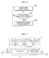
- FIG. 6 is a flowchart illustrating the operation of a mode changing unit according to an embodiment of the present invention.
- FIG. 7 is a schematic diagram illustrating the operation of a packet capture unit according to an embodiment of the present invention.
- FIG. 8 is a flowchart illustrating the operation of the packet capture unit according to an embodiment of the present invention.
- FIG. 9 is a schematic diagram illustrating the operation of a packet detection unit according to an embodiment of the present invention.
- FIG. 10 is a flowchart illustrating the operation of the packet detection unit according to an embodiment of the present invention.
- FIG. 11 is a table of detection policies according to an embodiment of the present invention.
- FIG. 12 is a flowchart illustrating the operation of a detection policy management unit according to an embodiment of the present invention.
- FIG. 13 is a flowchart illustrating the operation of a packet parsing unit according to an embodiment of the present invention.
- FIG. 14 is a flowchart illustrating the operation of a packet analysis unit according to an embodiment of the present invention.
- FIGS. 15 through 19 are flowcharts illustrating a process in which the packet analysis unit determines whether a GTP packet is an abnormal GTP packet according to various embodiments of the present invention
- FIG. 20 is a flowchart illustrating the operation of the packet analysis unit according to an embodiment of the present invention.
- FIG. 21 is a flowchart illustrating a method of preventing the intrusion of an abnormal GTP packet according to an embodiment of the present invention.
- each block of the flowchart illustrations may represent a module, segment, or portion of code, which comprises one or more executable instructions for implementing the specified logical function(s). It should also be noted that in some alternative implementations, the functions noted in the blocks may occur out of the order. For example, two blocks shown in succession may in fact be executed substantially concurrently or the blocks may sometimes be executed in the reverse order, depending upon the functionality involved.
- FIGS. 1 and 2 are schematic diagrams of systems 1000 and 2000 for preventing the intrusion of an abnormal GPRS tunneling protocol (GTP) packet according to various embodiments of the present invention.
- FIG. 3 is a schematic diagram of a mobile communication system which includes one of the systems 1000 and 2000 for preventing the intrusion of an abnormal GTP packet shown in FIGS. 1 and 2 .
- the system 1000 for preventing the intrusion of an abnormal GTP packet may include a system management unit 100 , a packet capture unit 200 , and a packet detection unit 300 .
- the system 2000 for preventing the intrusion of an abnormal GTP packet may further include a shared memory 400 , a graphical user interface (GUI) 500 , a database 600 , and network interface cards (NICs) 700 .
- GUI graphical user interface
- NICs network interface cards
- a GTP packet is classified into a GTP-C packet used for signalling between a serving GPRS support node (SGSN) and a gateway GPRS support node (GGSN) and a GTP-U packet used for data transmission between the SGSN and the GGSN.
- the GTP-C packet is used to set, delete, and update a data call between an SGSN and a GGSN within a mobile Internet network such as 3G/LTE/4G.
- user equipment such as a smart phone
- the GTP-U packet is used to carry user data between an SGSN and a GGSN within a mobile Internet network such as 3G/LTE/4G.
- GTP-in-GTP refers to a case where a data call setting message is transmitted by setting up a normally connected data call (that is, a case where a GTP-C packet is encapsulated in a GTP-U packet and transmitted accordingly), a case where a GGSN processes a GTP-C packet encapsulated in a GTP-U packet as a normal data call setting request (?), or a case where a GTP-U packet is encapsulated in another GTP-U packet and transmitted accordingly.
- GTP-in-GTP can also be referred to as GTP-over-GTP.
- GTP-in-GTP and GTP-over-GTP will collectively be referred to as abnormal GTP packets in the present specification.
- operation modes of a system include an intrusion prevention system (IPS) mode and a bypass mode.
- IPS intrusion prevention system
- bypass mode the system transmits all input GTP packets without filtering them.
- GTP-C packets and GTP-U packets can be used between a radio network controller (RNC) and an SGSN and between the SGSN and a GGSN within a mobile Internet network such as 3G/LT/4G. Therefore, the systems 1000 and 2000 for preventing the intrusion of an abnormal GTP packet according to the embodiments of the present invention can be placed between the RNC and the SGSN and between the SGSN and the GGSN, as shown in FIG. 3 .
- RNC radio network controller
- the system 1000 or 2000 for preventing the intrusion of an abnormal GTP packet is located between the RNC and the SGSN and between the SGSN and the GGSN, that is, located at a Gn interface.
- the system 1000 or 2000 can also be located in various network sections in which GTP packets are communicated. That is, the system 1000 or 2000 can be placed in a network section, in which GTP packets are communicated, to receive a GTP packet, analyze the GTP packet, and determine whether to drop the GTP packet based on the analysis result.
- the system 1000 or 2000 may be connected to the SGSN or the GGSN. Specifically, the system 1000 or 2000 may be connected to the SGSN or the GGSN to receive a GTP packet, analyze the GTP packet, and determine whether to drop the GTP packet based on the analysis result.
- the SGSN and the GGSN are illustrated in FIG. 3 as elements of the mobile communication system.
- the mobile communication system can include various elements other than the SGSN and the GGSN, and the system 1000 or 2000 can connect to all elements which communicate GTP packets among the various elements and perform a GTP packet intrusion prevention algorithm.
- the system 1000 or 2000 can also be placed within the SGSN and/or the GGSN. That is, the system 1000 or 2000 can be placed within the SGSN and/or the GGSN to perform a GTP packet intrusion prevention algorithm.
- the SGSN and the GGSN are illustrated in FIG. 3 as elements of the mobile communication system.
- the mobile communication system can include various elements other than the SGSN and the GGSN, and the system 1000 or 2000 can be placed within all elements which communicate GTP packets among the various elements and perform a GTP packet intrusion prevention algorithm.
- the system management unit 100 may include a monitoring unit 110 which monitors the state of the system 1000 for preventing the intrusion of an abnormal GTP packet and a mode changing unit 120 which changes the operation mode of the system 1000 based on the state of the system 1000 .
- the system management unit 100 may further include a mode management unit 130 which identifies from the GUI 500 whether the operation mode of the system 2000 has been changed.
- the monitoring unit 110 determines whether the system 1000 or 2000 is in a failure state by monitoring the state of the system 1000 or 2000 . When the system 1000 or 2000 is in the failure state, the operation mode of the system 1000 or 2000 may be changed. In some embodiments of the present invention, the monitoring unit 110 may monitor the state of the system 1000 or 2000 only when the system 1000 or 2000 operates in the IPS mode and, when determining that the system 1000 or 2000 is in the failure state based on the monitoring result, may request the mode changing unit 120 to change the operation mode of the system 1000 or 2000 to the bypass mode.
- the mode changing unit 120 may transmit information about the mode change of the system directly to the packet capture unit 200 .
- the mode changing unit 120 may store the information about the mode change in the shared memory 400 , and the packet capture unit 200 may access the shared memory 400 and obtain the information about the mode change of the system.
- the operation of the system management unit 100 will now be described in greater detail with reference to FIGS. 2 and 4 through 6 .
- FIG. 4 is a schematic diagram illustrating the operation of the system management unit 100 according to an embodiment of the present invention.
- FIG. 5 is a flowchart illustrating the operation of the system management unit 100 according to an embodiment of the present invention.
- FIG. 6 is a flowchart illustrating the operation of the mode changing unit 120 according to an embodiment of the present invention.
- the system management unit 100 may initiate the settings of a system before starting the system (operation S 501 ). To initiate the settings of the system, the system management unit 100 may set the shared memory 400 , set the operation mode of the system to the bypass mode, and initiate a packet information storage area 420 and an analysis result storage area 430 within the shared memory 400 .
- the system management unit 100 may manage an operation mode input from the GUI 500 (operation S 502 ).
- the system 2000 for preventing the intrusion of an abnormal GTP packet may further include the GUI 500 .
- a user or administrator can set the operation mode of the system using the GUI 500 .
- the GUI 500 may transmit a mode change request to the mode management unit 130 and/or the monitoring unit 110 of the system management unit 100 .
- the mode management unit 130 may receive information about whether the operation mode of the system has been changed, that is, a mode change request from the GUI 500 (operation S 601 ) and determine whether the operation mode of the system has been changed (operation S 602 ).
- the mode management unit 130 may store information about the mode change of the system in a mode information storage area 410 of the shared memory 400 directly or through the mode changing unit 120 (operation S 603 ).
- the time when the operation mode of the system was changed and the type of an operation mode to which the operation mode of the system was changed may be stored in the mode information storage area 410 of the shared memory 400 .
- a ‘check’ value may be set to zero. As will be described below, the check value may be set to one when the packet capture unit 200 checks whether the operation mode of the system has been changed.
- the mode management unit 130 has been described as a separate element from the monitoring unit 110 and the mode changing unit 120 . However, it is obvious that the mode management unit 130 can be integrated with the monitoring unit 110 or the mode changing unit 120 .
- the system management unit 100 may check the operation mode of the system (operation S 503 ) and determine whether the operation mode of the system is the IPS mode (operation S 504 ).
- the operation mode of the system is the bypass mode
- the system transmits all input GTP packets without filtering them. In this case, there is no need to determine whether the system is in the failure state. Therefore, the system management unit 100 waits until the operation mode of the system is changed to the IPS mode.
- the system management unit 100 may determine whether a timer has elapsed (operation S 505 ). Whether the system is in the failure state can be determined periodically using the timer.
- the monitoring unit 110 of the system management unit 100 may determine whether the system is in the failure state by monitoring the state of the system.
- the monitoring unit 110 may check the analysis result storage area 430 of the shared memory 400 and calculate the number of GTP packets unanalyzed by a packet analysis unit 320 of the packet detection unit 300 among GTP packets stored by a packet management unit 210 of the packet capture unit 200 (operation S 506 ). When the number of the unanalyzed GTP packets is equal to or greater than a threshold value (operation S 507 ), the monitoring unit 110 may determine that the system is in the failure state and set the operation of the system to the bypass mode (operation S 512 ).
- the analysis result storage area 430 of the shared memory 400 may store a packet ID for identifying each GTP packet, an analysis result of each GTP packet, and a check value indicating whether the packet capture unit 200 has checked the analysis result.
- a GTP packet stored in the shared memory 400 by the packet management unit 210 of the packet capture unit 200 may be identified by a packet ID, and an analysis result of the GTP packet is initially recorded as Null. After the GTP packet is analyzed by the packet analysis unit 320 of the packet detection unit 300 , the analysis result of the GTP packet is recorded as Drop or Bypass.
- the monitoring unit 110 may check this analysis result storage area 430 of the shared memory 400 and calculate the number of GTP packets unanalyzed by the packet analysis unit 320 , that is, the number of GTP packets whose analysis result values are Null. When the calculated number of GTP packets is equal to or greater than a preset threshold value, the monitoring unit 110 may determine that the system is in the failure state and change the operation of the system to the bypass mode in order to prevent malfunctions caused by the failure of the system.
- whether the system is in the failure state is determined based on whether the number of unanalyzed GTP packets is equal to or greater than a threshold value. However, in some embodiments of the present invention, whether the system is in the failure state may be determined based on whether the number of GTP packets unanalyzed for a predetermined period of time is equal to or greater than a threshold value or based on whether a ratio of the number of unanalyzed GTP packets to the total number of GTP packets is equal to or greater than a threshold ratio.
- the monitoring unit 110 identifies whether the packet detection unit 300 is operating by checking a process status (PS) command related to the operation of a processor (operation S 508 ).
- PS process status
- the monitoring unit 110 may determine that the system is in the failure state and set the operation mode of the system to the bypass mode (operation S 512 ).
- the monitoring unit 110 may calculate a traffic input/output error of the system by checking inbound traffic and outbound traffic of the system (operation S 510 ). When the traffic input/output error is equal to or greater than a threshold value (operation S 511 ), the monitoring unit 110 may determine that the system is in the failure state and set the operation mode of the system to the bypass mode (operation S 512 ).
- the traffic input/output error may be a value obtained by subtracting the amount of outbound traffic and the number of GTP packets determined to be dropped by a detection result checking unit 220 from the amount of inbound traffic.
- a GTP packet determined to be dropped refers to a GTP packet that is received by or input to the system but is not transmitted or output to another destination from the system. Therefore, the traffic input/output error denotes the amount of traffic currently being processed within the system.
- the monitoring unit 110 may determine that the system is in the failure state and change the operation mode of the system to the bypass mode in order to prevent malfunctions caused by the failure of the system.
- whether the system is in the failure state is determined based on whether the traffic input/output error is equal to or greater than a threshold value. However, in some embodiments of the present invention, whether the system is in the failure state may be determined based on whether the traffic input/output error for a predetermined period of time is equal to or greater than a threshold value or based on whether a ratio of the traffic input/output error to the total amount of inbound traffic is equal to or greater than a threshold ratio.
- whether the system is in the failure state is determined in the order of operations S 506 , S 508 and S 510 .
- the present invention is not limited to this order. It is obvious that the operations S 506 , S 508 and S 510 can also be performed in the reverse order or simultaneously.
- the packet capture unit 200 may include the packet management unit 210 which stores information about a GTP packet based on the operation mode of the system and the detection result checking unit 220 which determines whether to drop the GTP packet.
- the packet capture unit 200 may include a receiving unit (not shown) which receives a GTP packet and a transmitting unit (not shown) which transmits a GTP packet.
- the packet capture unit 200 may be connected to the NICs 700 .
- the receiving and transmitting units of the packet capture unit 200 may respectively be connected to the NICs 700 for processing high-volume packets at high speed to realize a device driver for packet processing at the kernel level.
- the receiving and transmitting units of the packet capture unit 200 can be connected to general NICs.
- the receiving and transmitting units of the packet capture unit 200 can be connected to hardware accelerated NICs to process high-volume packets.
- these various NICs are generalized as NICs.
- the packet management unit 210 may store information about a GTP packet based on the operation mode of the system. That is, when the operation mode of the system is the bypass mode, the packet management unit 210 may transmit a GTP packet received by the system. When the operation mode of the system is the IPS mode, the packet management unit 210 may store the received GTP packet. Referring to FIG. 1 , the packet management unit 210 may store a received GTP packet and transmit the GTP packet to the packet detection unit 300 . Alternatively, referring to FIG. 2 , information about the GTP packet may be stored in the shared memory 400 , and the packet detection unit 300 may access the shared memory 400 and obtain the information about the GTP packet.
- the detection result checking unit 220 may determine whether to drop a GTP packet based on an analysis result of the GTP packet received from the packet detection unit 300 and transmit the determination result to the packet management unit 210 .
- the detection result checking unit 220 may receive the analysis result of the GTP packet directly from the packet detection unit 300 .
- the detection result checking unit 220 may receive the analysis result of the GTP packet through the shared memory 400 .
- FIG. 7 is a schematic diagram illustrating the operation of the packet capture unit 200 according to an embodiment of the present invention.
- FIG. 8 is a flowchart illustrating the operation of the packet capture unit 200 according to an embodiment of the present invention.
- the packet capture unit 200 may load setting information, that is, information about the operation mode of a system (operation S 801 ). As shown in FIG. 7 , the packet management unit 210 may load a system operation mode stored in the mode information storage area 410 of the shared memory 400 . As described above, when the operation mode of the system is changed, the check value of the mode information storage area 410 may be set to zero. However, when the packet management unit 210 loads a system operation mode, the check value may be set to one.
- the packet management unit 210 may check information about an input GTP packet (operation S 802 ), check the operation mode of the system (operation S 804 ) when information exists in the GTP packet (operation S 803 ), and determine whether the operation mode of the system is the IPS mode (operation S 805 ).
- the packet management unit 210 may forward the input GTP packet normally (operation S 807 ).
- the operation mode of the system When the operation mode of the system is the IPS mode, it should be analyzed whether the GTP packet is an abnormal GTP packet, and the GTP packet should be controlled based on the analysis result. Therefore, when the operation mode of the system is the IPS mode, it may be determined whether the GTP packet is a GTP-U packet (operation S 806 ). As described above, a GTP-U packet that has another packet (such as GTP-C packet) encapsulated therein is defined as an abnormal GTP packet. Therefore, when the GTP packet is not the GTP-U packet, it can be forwarded normally (operation S 807 ). However, when the GTP packet is the GTP-U packet, it should be determined whether the GTP packet is an abnormal GTP packet.
- a packet ID may be set for the GTP packet (operation S 808 ), and the packet ID and the information about the GTP packet may be stored in the shared memory 400 (operation S 809 ).
- the time when the information about the GTP packet was uploaded, the packet ID, and the information about the GTP packet may be stored in the shared memory 400 , specifically, in the packet information storage area 420 of the shared memory 400 .
- a unique packet ID is assigned to each GTP packet, and a packet ID assigned to a GTP packet which has been determined to be normal or abnormal can be reused.
- the detection result checking unit 220 checks analysis results stored in the shared memory 400 by the packet detection unit 300 (operation S 810 ) and determines whether an analysis result of the GTP packet exists (operation S 811 ). As described above, whether a GTP packet stored in the shared memory 400 has been analyzed and an analysis result of the GTP packet are recorded in the analysis result storage area 430 of the shared memory 400 . When the analysis result of the GTP packet does not exist, that is, when the GTP packet has not yet been analyzed, the analysis result of the GTP packet is recorded as Null. Therefore, when the analysis result is Null, the analysis result of the GTP packet may be checked again. When the analysis result of the GTP packet exists, it may be determined whether the analysis result is Drop or Bypass (operation S 812 ). When the analysis result is Bypass, the GTP packet is forwarded normally (operation S 813 ). When the analysis result is not Bypass but Drop, the GTP packet may be dropped (operation S 814 ).
- the packet detection unit 300 may include a packet parsing unit 310 which parses information about a GTP packet and the packet analysis unit 320 which analyzes the parsed information about the GTP packet.
- the packet analysis unit 320 may include a detection policy management unit 321 which manages a detection policy.
- the packet parsing unit 310 may receive information about a GTP packet directly from the packet management unit 210 of the packet capture unit 200 .
- the packet management unit 210 may store the information about the GTP packet in the packet information storage area 420 of the shared memory 400 , and the packet parsing unit 310 may access the packet information storage area 420 of the shared memory 400 and obtain the information about the GTP packet.
- the packet analysis unit 320 may transmit an analysis result directly to the detection result checking unit 220 of the packet capture unit 200 .
- FIG. 1 the packet analysis unit 320 may transmit an analysis result directly to the detection result checking unit 220 of the packet capture unit 200 .
- the packet analysis unit 320 may store the analysis result in the analysis result storage area 430 of the shared memory 400 , and the detection result checking unit 220 may access the analysis result storage area 430 of the shared memory 400 and obtain information about the analysis result.
- the operation of the packet detection unit 300 which includes the packet parsing unit 310 and the packet analysis unit 320 will now be described in greater detail with reference to FIGS. 9 and 10 .
- FIG. 9 is a schematic diagram illustrating the operation of the packet detection unit 300 according to an embodiment of the present invention.
- FIG. 10 is a flowchart illustrating the operation of the packet detection unit 300 according to an embodiment of the present invention.
- the packet detection unit 300 may load policy setting information (operation S 1001 ).
- the packet detection unit 300 may load the policy the setting information from the database 600 using the detection policy management unit 321 included in the packet analysis unit 320 .
- the policy setting information may include the intervals at which a detection policy is checked and information about an initial detection policy.
- the policy setting information may be stored in the database 600 or may be input by a user or administrator through the GUI 500 .
- the packet detection unit 300 may manage a detection policy (operation S 1002 ).
- the packet detection unit 300 may manage the detection policy using the detection policy management unit 321 of the packet analysis unit 320 .
- the operation of the detection policy management unit 321 will now be described in greater detail with reference to FIGS. 11 and 12 .
- FIG. 11 is a table of detection policies according to an embodiment of the present invention.
- FIG. 12 is a flowchart illustrating the operation of the detection policy management unit 321 according to an embodiment of the present invention.
- a detection policy is a policy that defines how each abnormal GTP packet will be processed according to the type of the abnormal GTP packet.
- the detection policy may consist of a rule ID, a rule type, whether a GTP packet is an IP packet, whether the GTP packet is bound for a GTP-C port or a GTP-U port, a processing policy, and whether the detection policy is active.
- the detection policy may be configured in the form of a table as shown in FIG. 11 .
- the rule ID is an ID used to identify each detection policy and may be set arbitrarily.
- an English alphabet in the rule ID is defined according to the rule type, and a number in the rule ID is defined for sub-classification of each rule type.
- the English alphabet and number in each rule ID can be defined in other ways.
- the rule type is used to identify the type of an abnormal GTP packet, that is, the type of a GTP-in-GTP or GTP-over-GTP packet.
- the packet analysis unit 320 may determine whether an input GTP packet is an abnormal GTP packet and determine the type of the abnormal GTP packet to be PDP Create Req, PDP Update Req, PDP Delete Req, GTP Echo Req, or GTP-U. Determining whether an input GTP packet is an abnormal GTP packet will be described later.
- the rule type of the detection policy is used to identify the above-described types of abnormal GTP packets. However, it is obvious that the rule type can also be defined to identify other types of abnormal GTP packets.
- the detection policy may include detailed criteria for subdividing each rule type.
- the detailed criteria may include whether a GTP packet is bound for an internal IP (i.e., whether the GTP packet is an IP packet) and a destination GTP port of the GTP packet.
- the detailed criteria may include whether a GTP packet is bound for the internal IP, that is, whether the GTP packet is an IP packet. This is because even if the GTP packet is an abnormal GTP packet, when the GTP packet is not bound for the internal IP, it may not cause system malfunctions.
- the detailed criteria may further include the destination GTP port of the GTP packet.
- the destination GTP port can be a GTP-U port or a GTP-C port and can be changed according to the rule type.
- the rule type when the rule type is PDP Create Req, PDP Update Req, or PDP Delete Req, it may be determined whether the destination GTP port is the GTP-C port.
- the rule type is GTP Echo Req, it may be determined whether the destination GTP port is the GTP-C port or the GTP-U port.
- the rule type is GTP-U, it may be determined whether the GTP port is the GTP-U port.
- Each detection policy may include a processing policy on how a GTP packet corresponding to the detection policy identified by a rule ID will be processed.
- the processing policy includes Bypass and Drop.
- Bypass denotes that a GTP packet corresponding to a detection policy identified by a rule ID will not be dropped but be transmitted as it is.
- Drop denotes that a GTP packet corresponding to a detection policy identified by a rule ID will not be transmitted but be dropped within the system.
- an abnormal GTP packet may be dropped. However, as described above, the abnormal GTP packet can also be transmitted without being dropped. In this case, the fact that the abnormal GTP packet existed may be recorded in the database 600 .
- Each detection policy may include information about whether the detection policy is active. When a detection policy is active, it may be determined whether a GTP packet corresponding to the detection policy exists. When the GTP packet corresponding to the detection policy exists, it may be processed according to the processing policy. When the detection policy is inactive, it may not be determined whether the GTP packet corresponding to the detection policy exists.
- the processing policy When the processing policy is Bypass, the GTP packet is transmitted in the same way as when the detection policy is inactive. Therefore, setting the processing policy to Bypass may be substantially the same as deactivating the detection policy. However, when the detection policy is active, the fact that such traffic actually exists may be recorded in the database 600 .
- the detection policy management unit 321 may determine whether a timer has elapsed (operation S 1201 ) and identify whether a detection policy has been changed only when the timer has elapsed (operation S 1202 ). Whether the detection policy has been changed can be identified by periodically monitoring whether the database 600 has been updated. As described above with reference to FIG. 10 , the time of the timer may be determined based on the intervals at which the detection policy included in the policy setting information loaded from the database 600 is checked. By checking whether the detection policy has been changed only when the timer has elapsed, the detection policy can be managed periodically.
- the detection policy management unit 321 may update the detection policy (operation S 1204 ) and may set detection policy update information to one in order to inform the packet detection unit 300 of the update of the detection policy (operation S 1205 ).
- the detection policy update information may include the time when the detection policy was updated and a value of one or zero indicating whether the detection policy has been updated.
- the packet parsing unit 310 of the packet detection unit 300 may load packet information from the packet information storage area 420 of the shared memory 400 (operation S 1003 ) and parse the packet information (operation S 1004 ).
- the operation of the packet parsing unit 310 will now be described in greater detail with reference to FIG. 13 .
- FIG. 13 is a flowchart illustrating the operation of the packet parsing unit 310 according to an embodiment of the present invention.
- the packet parsing unit 310 may be a module which parses major information needed to analyze a GTP packet from the GTP packet before the packet analysis unit 320 analyzes the GTP packet.
- the packet parsing unit 310 may obtain information about a GTP packet stored in the shared memory 400 , convert the obtained information into structured packet information, and transmit the structured packet information to the packet analysis unit 320 .
- the packet parsing unit 310 may receive information about a GTP packet stored in the shared memory 400 (operation S 1301 ) and extract an uplink tunneling endpoint identifier (TEID) of a GTP-U header (operation S 1302 ) and a user packet (operation S 1303 ).
- the packet parsing unit 310 may determine whether the extracted user packet is an IP packet, that is, whether the extracted user packet is bound for the internal IP (operation S 1304 ). When the extracted user packet is not the IP packet, the packet parsing unit 310 may immediately structure the information about the GTP packet (operation S 1308 ) and transmit the structured packet information to the packet analysis unit 320 (operation S 1309 ).
- the packet parsing unit 310 may extract a destination IP and a destination port (operation S 1305 ), extract a length of a GTP-U packet (operation S 1306 ), and extract first 200 bytes of a payload of the GTP-U packet and a length of the payload (operation S 1307 ).
- the length of the GTP-U packet may be extracted using information stored in the header of the GTP-U packet. In the present specification, a case where values of the first 200 bytes of the payload of the GTP-U packet are extracted is described as an embodiment.
- high-order byte values that are extracted are not limited to the values of the first 200 bytes of the payload but can be set flexibly to detect an abnormal GTP packet.
- the packet parsing unit 310 may form structured packet information as shown in FIG. 13 by structuring various extracted information and transmit the structured packet information to the packet analysis unit 320 (operation S 1309 ).
- the packet detection unit 300 may check the detection policy update information (operation S 1005 ). As described above, when the detection policy is updated, the detection policy update information is set to one. Therefore, the packet detection unit 300 can identify whether the detection policy has been updated by checking the detection policy update information (operation S 1006 ). When the detection policy has not been updated, a GTP packet may be analyzed based on the initial detection policy obtained when the policy setting information was loaded initially (operation S 1009 ). When the detection policy has been updated, the detection policy may be reset to the updated detection policy (operation S 1007 ), the detection policy update information may be set to zero (operation S 1008 ), and the GTP packet may be analyzed based on the reset detection policy (operation S 1009 ).
- FIG. 14 is a flowchart illustrating the operation of the packet analysis unit 320 according to an embodiment of the present invention.
- FIGS. 15 through 19 are flowcharts illustrating a process in which the packet analysis unit 320 determines whether a GTP packet is an abnormal GTP packet according to various embodiments of the present invention.
- FIG. 20 is a flowchart illustrating the operation of the packet analysis unit 320 according to an embodiment of the present invention.
- the packet analysis unit 320 may receive structured packet information about a GTP packet from the packet parsing unit 310 (operation S 1401 ). Then, the packet analysis unit 320 may determine whether the GTP packet is an IP packet based on the structured packet information (operation S 1402 ). When the GTP packet is not the IP packet, the packet analysis unit 320 may identify rule matching information from a detection policy (operation S 1413 ). Identifying the rule matching information will be described later.
- the packet analysis unit 320 may analyze a length of a GTP-U packet, byte values of a payload of the GTP-U packet, and a length of the payload of the GTP-U packet (operation S 1403 ). Specifically, the packet analysis unit 320 may determine whether the GTP packet is an abnormal GTP packet based on the length of the GTP-U packet, values of high-order bytes of the payload of the GTP-U packet, and the length of the payload.
- the packet analysis unit 320 may determine whether the GTP packet is PDP Create Req (operation S 1404 ), PDP Update Req (operation S 1406 ), PDP Delete Req (operation S 1408 ), GTP Echo Req (operation S 1410 ), or GTP-U (operation S 1411 ).
- whether the GTP packet is an abnormal GTP packet is determined in the order of PDP Create Req, PDP Update Req, PDP Delete Req, GTP Echo Req, and GTP-U.
- the GTP packet is any one of the above abnormal GTP packets can be determined in a different order from the above order or simultaneously.
- the packet analysis unit 320 may determine a GTP packet to be PDP Create Req among the abnormal GTP packets as follows.
- the packet analysis unit 320 may receive a payload of a GTP-U packet (operation S 1501 ), analyze first 2 bytes of the payload (operation S 1502 ), and determine whether a value of the first 2 bytes is 0x3210 (operation S 1503 ). When the value of the first 2 bytes is not 0x3210, the GTP packet may be detected as a normal packet (operation S 1504 ).
- 4 bytes from (and including) a fifth byte of the payload of the GTP-U packet may be analyzed (operation S 1505 ). After the 4 bytes from the fifth byte of the payload of the GTP-U packet are analyzed, it may be determined whether values of the 4 bytes from the fifth byte are all 0x00 (operation S 1506 ). When the values of the 4 bytes from the fifth byte are all 0x00, it may determined whether a length of the payload of the GTP-U packet is greater than 170 and less than 180 (operation S 1507 ).
- the GTP packet may be determined to be an abnormal GTP packet (i.e., PDP Create Req) (operation S 1509 ).
- the packet analysis unit 320 may extract additional fields (IMSI, MSISDN) (operation S 1405 ) and identify rule matching information (operation S 1413 ).
- the packet analysis unit 320 may determine a GTP packet to be PDP Update Req among the abnormal GTP packets as follows.
- the packet analysis unit 320 may receive a payload of a GTP-U packet (operation S 1601 ), analyze first 2 bytes of the payload (operation S 1602 ), and determine whether a value of the first 2 bytes is 0x3212 (operation S 1603 ). When the value of the first 2 bytes is not 0x3212, the GTP packet may be detected as a normal packet (operation S 1604 ).
- a length of the payload of the GTP-U packet is greater than 80 and less than 100 (operation S 1605 ).
- the length of the payload is greater than 80 and less than 100, it may determined whether a difference between a length of the GTP-U packet and a value of 2 bytes from (and including) a third byte of the payload of the GTP-U packet is 16, that is, whether a value obtained by subtracting 16 from the length of the GTP-U packet is the value of the 2 bytes from the third byte of the payload of the GTP-U packet (operation S 1606 ).
- the GTP packet may be determined to be an abnormal GTP packet (i.e., PDP Update Req) (operation S 1607 ).
- the packet analysis unit 320 may extract an additional field (uplink TEID(Ct 1 )) (operation S 1407 ) and identify rule matching information (operation S 1413 ).
- the packet analysis unit 320 may determine a GTP packet to be PDP Delete Req among the abnormal GTP packets as follows.
- the packet analysis unit 320 may receive a payload of a GTP-U packet (operation S 1701 ), analyze first 2 bytes of the payload (operation S 1702 ), and determine whether a value of the first 2 bytes is 0x3214 (operation S 1703 ). When the value of the first 2 bytes is not 0x3214, the GTP packet may be detected as a normal packet (operation S 1704 ).
- a length of the payload of the GTP-U packet is greater than 20 and less than 25 (operation S 1705 ).
- the length of the payload is greater than 20 and less than 25, it may determined whether a difference between a length of the GTP-U packet and a value of 2 bytes from (and including) a third byte of the payload of the GTP-U packet is 16, that is, whether a value obtained by subtracting 16 from the length of the GTP-U packet is the value of the 2 bytes from the third byte of the payload of the GTP-U packet (operation S 1706 ).
- the GTP packet may be determined to be an abnormal GTP packet (i.e., PDP Delete Req) (operation S 1707 ).
- the packet analysis unit 320 may extract an additional field (uplink TEID(Ct 1 )) (operation S 1409 ) and identify rule matching information (operation S 1413 ).
- the packet analysis unit 320 may determine a GTP packet to be GTP Echo Req among the abnormal GTP packets as follows.
- the packet analysis unit 320 may receive a payload of a GTP-U packet (operation S 1801 ), analyze first 2 bytes of the payload (operation S 1802 ), and determine whether a value of the first 2 bytes is 0x3201 (operation S 1803 ). When the value of the first 2 bytes is not 0x3201, the GTP packet may be detected as a normal packet (operation S 1804 ).
- the value of the first 2 bytes is 0x3201
- the length of the payload is 12, it may determined whether a difference between a length of the GTP-U packet and a value of 2 bytes from (and including) a third byte of the payload of the GTP-U packet is 16, that is, whether a value obtained by subtracting 16 from the length of the GTP-U packet is the value of the 2 bytes from the third byte of the payload of the GTP-U packet (operation S 1806 ).
- the GTP packet may be determined to be an abnormal GTP packet (i.e., GTP Echo Req) (operation S 1807 ).
- the packet analysis unit 320 may identify rule matching information (operation S 1413 ).
- the packet analysis unit 320 may determine a GTP packet to be GTP-U Req among the abnormal GTP packets as follows.
- the packet analysis unit 320 may receive a payload of a GTP-U packet (operation S 1901 ), analyze first 2 bytes of the payload (operation S 1902 ), and determine whether a value of the first 2 bytes is 0x30ff (operation S 1903 ). When the value of the first 2 bytes is not 0x30ff, the GTP packet may be detected as a normal packet (operation S 1904 ).
- the GTP packet may be determined whether a difference between a length of the GTP-U packet and a value of 2 bytes from (and including) a third byte of the payload of the GTP-U packet is 16, that is, whether a value obtained by subtracting 16 from the length of the GTP-U packet is the value of the 2 bytes from the third byte of the payload of the GTP-U packet (operation S 1905 ).
- the GTP packet may be determined to be an abnormal GTP packet (i.e., GTP-U Req) (operation S 1906 ).
- the packet analysis unit 320 may extract an additional field (uplink TEID(data)) (operation S 1412 ) and identify rule matching information (operation S 1413 ).
- a value (e.g., 0x3210 in FIG. 15 or 0x3212 in FIG. 16 ) compared with a value of first 2 bytes of a payload of a GTP-U packet may be set based on a GTP version.
- an abnormal GTP packet refers to a GTP-C or GTP-U packet encapsulated in a GTP-U packet, that is, a GTP packet encapsulated in another GTP packet. Therefore, the version of a GTP packet that can be encapsulated may determine the value compared with the value of the first 2 bytes of the payload of the GTP-U packet. Accordingly, the value compared with the value of the first 2 bytes of the payload may be set based on the version of the GTP packet.
- the value (e.g., 0x3210 in FIG. 15 or 0x3212 in FIG. 16 ) compared with the value of the first 2 bytes of the payload of the GTP-U packet may be set based at least partially on the GTP version. If the value (e.g., 0x3210 in FIG. 15 or 0x3212 in FIG. 16 ) compared with the value of the first 2 bytes of the payload of the GTP-U packet is set based at least partially on the GTP version, it means that the value compared with the value of the first 2 bytes of the payload is set based partially or entirely on the GTP version.
- a value (e.g., 170 to 180 in FIG. 15 or 80 to 100 in FIG. 16 ) compared with a length of the payload of the GTP-U packet may be set based on an access point name (APN) field.
- the APN field may be included in a GTP-C packet.
- a different APN may be given to each mobile communication service provider, and the APN field may be changed accordingly. Since the length of the payload of the GTP-U packet can vary according to the APN field, the value compared with the length of the payload may be set based on the APN field.
- the value (e.g., 170 to 180 in FIG. 15 or 80 to 100 in FIG. 16 ) compared with the length of the payload of the GTP-U packet may be set based at least partially on the APN field. If the value (e.g., 170 to 180 in FIG. 15 or 80 to 100 in FIG. 16 ) compared with the length of the payload of the GTP-U packet is set based at least partially on the APN field, it means that the value compared with the length of the payload is set based entirely on the APN field or based on the APN field and other fields.
- a length of the GTP-U packet may be a length of a GTP packet classified as a GTP-U packet.
- a value of 2 bytes from a third byte of the payload of the GTP-U packet, that is, a value of third and fourth bytes of the payload may be the length of the GTP-U packet.
- Byte values and a payload length value used to determine whether a GTP packet is an abnormal packet in FIGS. 15 through 19 can vary flexibly according to an applied network or a communication service provider.
- the byte values and the payload length value used to determine whether a GTP packet is an abnormal GTP packet may be different from the values used in FIGS. 15 through 19 and may be selected from a predetermined range.
- the byte values and the payload length value used to determine whether a GTP packet is an abnormal GTP packet may be set variously based on the APN field as well as other omittable message fields.
- rule matching information may be identified (operation S 1413 ). Identifying rule matching information is a process of identifying whether an active detection policy matching a GTP packet exists. Identifying rule matching information will now be described in greater detail with reference to FIG. 20 .
- the packet analysis unit 320 may determine whether an abnormal GTP packet is an IP packet based on information about the abnormal GTP packet (operation S 2002 ). When determining that the GTP packet is the IP packet, the packet analysis unit 320 may add the determination result, that is, may store information indicating that the GTP packet is bound for the internal IP (operation S 2003 ).
- the packet analysis unit 320 may determine whether a destination of the GTP packet is a GTP-C port (operation S 2004 ). When determining that the destination of the GTP packet is the GTP-C port, the packet analysis unit 320 may add the determination result, that is, may store information indicating that the GTP packet is bound for the GTP-C port (operation S 2005 ).
- the packet analysis unit 320 may determine whether the destination of the GTP packet is a GTP-U port (operation S 2006 ). When determining that the destination of the GTP packet is the GTP-U port, the packet analysis unit 320 may add the determination result, that is, may store information indicating that the GTP packet is bound for the GTP-U port (operation S 2005 ). For ease of description, the destination of the GTP packet is determined in the order of the GTP-C port and the GTP-U port. However, it is obvious that the destination of the GTP packet can also be determined in the order of the GTP-U port and the GTP-C port.
- the packet analysis unit 320 may identify active rules (operation S 2008 ). Specifically, the packet analysis unit 320 may identify active detection policies among a plurality of detection policies.
- the packet analysis unit 320 may identify whether any one of the active detection policies matches the GTP packet (operation S 2009 ). When no active detection policy matches the GTP packet, the GTP packet may be detected as a normal packet, and an analysis result of the GTP packet may be generated as Bypass (operation S 2010 ). When one of the active detection policies matches the GTP packet, the GTP packet may be detected as an abnormal GTP packet, and an analysis result of the GTP packet may be generated by determining whether to bypass or drop the GTP packet according to the matching detection policy (operation S 2011 ).
- an analysis result may be generated by identifying rule matching information (operation S 1414 ), and the generated analysis result may be transmitted to the shared memory 400 (operation S 1415 ).
- the generated analysis result can be transmitted to a separate analysis result management module (operation S 1010 ).
- FIG. 21 is a flowchart illustrating a method of preventing the intrusion of an abnormal GTP packet according to an embodiment of the present invention.
- the state of a system for preventing the intrusion of an abnormal GTP packet may be monitored (operation S 2101 ).
- the operation of monitoring the state of the system is substantially the same as that described above with reference to FIGS. 4 through 6 , and thus a repetitive description thereof will be omitted.
- An operation mode of the system may be changed based on the monitored state of the system (operation S 2102 ).
- the operation of changing the operation mode of the system based on the state of the system is substantially the same as that described above with reference to FIGS. 4 through 6 , and thus a repetitive description thereof will be omitted.
- Information about a GTP packet may be stored based on the operation mode of the system (operation S 2103 ).
- the operation of storing the information about the GTP packet in a shared memory based on the operation mode of the system is substantially the same as that described above with reference to FIGS. 7 and 8 , and thus a repetitive description thereof will be omitted.
- the information about the GTP packet may be parsed (operation S 2104 ).
- the operation of parting the information about the GTP packet is substantially the same as that described above with reference to FIGS. 9 through 20 , and thus a repetitive description thereof will be omitted.
- the information about the GTP packet may be analyzed (operation S 2105 ).
- the operation of analyzing the information about the GTP packet that is, the operation of parsing the GTP packet, structuring the parsed GTP packet, and analyzing information about the structured GTP packet is substantially the same as that described above with reference to FIGS. 9 through 20 , and thus a repetitive description thereof will be omitted.
- Embodiments of the present invention provide at least one of the following advantages.
- an abnormal GTP packet such as a GTP-in-GTP packet in which a GTP-C packet or a GTP-U packet is encapsulated in a GTP-U packet cannot be generated. Therefore, there has been no consideration given to a technology for detecting such an abnormal GTP packet.
- a system and method for preventing the intrusion of an abnormal GTP packet according to the present invention can efficiently detect such an abnormal GTP packet.
- an abnormal GTP packet is detected based on a length of a GTP-U packet as well as byte values of a payload of the GTP-U packet and a length of the payload. Therefore, the system and method for preventing the intrusion of an abnormal GTP packet can be employed to detect abnormal GTP packets more accurately by reducing a detection error rate.
- steps of the method or algorithm described may be directly implemented using hardware, a software module executed by a processor, or the combination thereof.
- the software module may be placed in a random access memory (RAM), a flash memory, a read-only memory (ROM), an electrically programmable ROM (EPROM), an electrically erasable programmable ROM (EEPROM), a register, a hard disk, a removable disk, a CD-ROM, or any storage medium of other forms well-known in the technical field.
- a storage medium is coupled to a processor so that the processor can read or write information from or into the storage medium.
- the storage medium may be integrated in the processor.
- the storage medium and the processor may be provided inside an application specific integrated circuit (ASIC).
- the ASIC may be provided inside user equipment.
- the storage medium and the processor may be provided as discrete components inside the user equipment.
Abstract
Description
Claims (18)
Applications Claiming Priority (4)
| Application Number | Priority Date | Filing Date | Title |
|---|---|---|---|
| KR1020110132974A KR101162284B1 (en) | 2011-12-12 | 2011-12-12 | System and method for anomaly gtp packet intrusion prevention |
| KR10-2011-0132974 | 2011-12-12 | ||
| KR10-2012-0048106 | 2012-05-07 | ||
| KR1020120048106A KR101366770B1 (en) | 2012-05-07 | 2012-05-07 | APPARATUS AND METHOD FOR DETECTING GTP-in-GTP PACKETS |
Publications (2)
| Publication Number | Publication Date |
|---|---|
| US20130148510A1 US20130148510A1 (en) | 2013-06-13 |
| US8948019B2 true US8948019B2 (en) | 2015-02-03 |
Family
ID=48571900
Family Applications (1)
| Application Number | Title | Priority Date | Filing Date |
|---|---|---|---|
| US13/549,273 Active 2033-04-09 US8948019B2 (en) | 2011-12-12 | 2012-07-13 | System and method for preventing intrusion of abnormal GTP packet |
Country Status (1)
| Country | Link |
|---|---|
| US (1) | US8948019B2 (en) |
Families Citing this family (6)
| Publication number | Priority date | Publication date | Assignee | Title |
|---|---|---|---|---|
| KR101541348B1 (en) * | 2014-04-09 | 2015-08-05 | 주식회사 윈스 | METHOD AND APPARATUS FOR MANAGING SESSION BASED GPRS Tunneling Protocol NETWORK |
| US10911353B2 (en) * | 2015-06-17 | 2021-02-02 | Extreme Networks, Inc. | Architecture for a network visibility system |
| CN107786981B (en) * | 2016-08-31 | 2021-06-04 | 华为技术有限公司 | Method and device for preventing signaling attack |
| CN108307385B (en) * | 2016-08-31 | 2021-06-29 | 华为技术有限公司 | Method and device for preventing signaling attack |
| WO2019035313A1 (en) * | 2017-08-18 | 2019-02-21 | 日本電信電話株式会社 | Intrusion prevention device, intrusion prevention method, and program |
| CN115408574A (en) * | 2021-05-28 | 2022-11-29 | 南宁富联富桂精密工业有限公司 | Data analysis method, device and computer readable storage medium |
Citations (9)
| Publication number | Priority date | Publication date | Assignee | Title |
|---|---|---|---|---|
| US20060075481A1 (en) | 2004-09-28 | 2006-04-06 | Ross Alan D | System, method and device for intrusion prevention |
| US20060206933A1 (en) | 2005-03-10 | 2006-09-14 | Stsn General Holdings Inc. | Security for mobile devices in a wireless network |
| KR20060118830A (en) | 2005-05-17 | 2006-11-24 | 엘지노텔 주식회사 | Signal packet controlling apparatus of w-cdma system using traffic monitoring and the method of the same |
| KR20080057161A (en) | 2006-12-19 | 2008-06-24 | 주식회사 케이티프리텔 | Intrusion protection device and intrusion protection method for point-to-point tunneling protocol |
| KR20090030642A (en) | 2007-09-20 | 2009-03-25 | 주식회사 케이티프리텔 | Method and system to analyze call quality in wcdma using ip multimedia subsystems |
| US20090172818A1 (en) * | 2007-11-25 | 2009-07-02 | Blake Stanton Sutherland | Methods and system for determining performance of filters in a computer intrusion prevention detection system |
| KR20100030900A (en) | 2008-09-11 | 2010-03-19 | 주식회사 케이티 | Method and system for intercepting unusual call in wireless data communication environment |
| US20110069663A1 (en) * | 2004-09-10 | 2011-03-24 | Juniper Networks, Inc. | Intercepting gprs data |
| KR101125817B1 (en) | 2011-10-31 | 2012-03-27 | 한국인터넷진흥원 | Apparatus and method for detecting gtp-in-gtp packets |
-
2012
- 2012-07-13 US US13/549,273 patent/US8948019B2/en active Active
Patent Citations (9)
| Publication number | Priority date | Publication date | Assignee | Title |
|---|---|---|---|---|
| US20110069663A1 (en) * | 2004-09-10 | 2011-03-24 | Juniper Networks, Inc. | Intercepting gprs data |
| US20060075481A1 (en) | 2004-09-28 | 2006-04-06 | Ross Alan D | System, method and device for intrusion prevention |
| US20060206933A1 (en) | 2005-03-10 | 2006-09-14 | Stsn General Holdings Inc. | Security for mobile devices in a wireless network |
| KR20060118830A (en) | 2005-05-17 | 2006-11-24 | 엘지노텔 주식회사 | Signal packet controlling apparatus of w-cdma system using traffic monitoring and the method of the same |
| KR20080057161A (en) | 2006-12-19 | 2008-06-24 | 주식회사 케이티프리텔 | Intrusion protection device and intrusion protection method for point-to-point tunneling protocol |
| KR20090030642A (en) | 2007-09-20 | 2009-03-25 | 주식회사 케이티프리텔 | Method and system to analyze call quality in wcdma using ip multimedia subsystems |
| US20090172818A1 (en) * | 2007-11-25 | 2009-07-02 | Blake Stanton Sutherland | Methods and system for determining performance of filters in a computer intrusion prevention detection system |
| KR20100030900A (en) | 2008-09-11 | 2010-03-19 | 주식회사 케이티 | Method and system for intercepting unusual call in wireless data communication environment |
| KR101125817B1 (en) | 2011-10-31 | 2012-03-27 | 한국인터넷진흥원 | Apparatus and method for detecting gtp-in-gtp packets |
Non-Patent Citations (7)
| Title |
|---|
| English abstract of KR101125817. 1 page. |
| Korean Notice of Allowance issued on Nov. 18, 2013 for corresponding KR Patent Application No. 10-2012-0048106. |
| Korean Office Action for Korean Patent Application No. 10-2011-0132974, mailed Feb. 20, 2012, 3 pages. |
| Notice of Allowance for Korean Patent Application No. 10-2011-0132974, mailed Mar. 29, 2012, 5 pages. |
| Office Action issued by the KIPO for Korean patent application No. 10-2012-0048106. 4 pages. |
| Universal Mobile Telecommunications System (UMTS); GPRS Tunnelling Protocol for User Plane (GTPv1-U) (3GPP TS 29.281 version 8.0.0 Release 8), 2011, pp. 1-25. * |
| Xuena Peng, GTP Security in 3G Core Network, 2010, IEEE, pp. 15-19. * |
Also Published As
| Publication number | Publication date |
|---|---|
| US20130148510A1 (en) | 2013-06-13 |
Similar Documents
| Publication | Publication Date | Title |
|---|---|---|
| US8948019B2 (en) | System and method for preventing intrusion of abnormal GTP packet | |
| US10412625B1 (en) | Systems and methods for tracking and calculating network usage in a network with multiple user plane functions | |
| EP3050258B1 (en) | Methods, systems, and computer readable media for diameter load and overload information and virtualization | |
| US9596154B2 (en) | Classifying client devices in a network | |
| US10291586B2 (en) | Monitoring wireless data consumption | |
| EP2806602A1 (en) | Feature extraction device, network traffic identification method, device and system. | |
| US8750133B2 (en) | Method and monitoring component for network traffic monitoring | |
| EP2515476A1 (en) | Method for the interception of GTP-C messages | |
| CN110557342B (en) | Apparatus for analyzing and mitigating dropped packets | |
| CN101341715A (en) | Methods and devices for defending a 3g wireless network against malicious attacks | |
| EP2613480A1 (en) | Communication quality monitoring system, communication quality monitoring method, and storage medium | |
| CN113364682B (en) | Data transmission method and device, storage medium and electronic device | |
| KR101388627B1 (en) | Apparatus for blocking abnormal traffic in 4g mobile network | |
| KR101563413B1 (en) | Communication system, base station, and method for coping with cyber attacks | |
| US9716643B2 (en) | Systems and methods for changing the frequency of retrieving monitoring data | |
| US11425014B2 (en) | Scalable in-band telemetry metadata extraction | |
| KR101162284B1 (en) | System and method for anomaly gtp packet intrusion prevention | |
| EP2996283A1 (en) | Systems and devices for determining key performance indicators using inferential statistics | |
| KR100694724B1 (en) | Signal Packet controlling apparatus of W-CDMA system using traffic monitoring and the method of the same | |
| EP2536073B1 (en) | Prioritizing lawful intercept sessions | |
| CN107210969B (en) | Data processing method based on software defined network and related equipment | |
| EP3641248B1 (en) | Traffic optimization device, communication system, traffic optimization method, and program | |
| US10516594B2 (en) | Systems and methods for changing the frequency of monitoring data | |
| US20210004308A1 (en) | Data processing method and system | |
| EP3289797B1 (en) | Load based signaling in a communication network |
Legal Events
| Date | Code | Title | Description |
|---|---|---|---|
| AS | Assignment |
Owner name: KOREA INTERNET & SECURITY AGENCY, KOREA, REPUBLIC Free format text: ASSIGNMENT OF ASSIGNORS INTEREST;ASSIGNORS:KANG, DONG WAN;OH, JOO HYUNG;KIM, SE KWON;AND OTHERS;REEL/FRAME:028555/0834 Effective date: 20120620 |
|
| STCF | Information on status: patent grant |
Free format text: PATENTED CASE |
|
| MAFP | Maintenance fee payment |
Free format text: PAYMENT OF MAINTENANCE FEE, 4TH YEAR, LARGE ENTITY (ORIGINAL EVENT CODE: M1551) Year of fee payment: 4 |
|
| MAFP | Maintenance fee payment |
Free format text: PAYMENT OF MAINTENANCE FEE, 8TH YR, SMALL ENTITY (ORIGINAL EVENT CODE: M2552); ENTITY STATUS OF PATENT OWNER: SMALL ENTITY Year of fee payment: 8 Free format text: PAYMENT OF MAINTENANCE FEE, 8TH YEAR, LARGE ENTITY (ORIGINAL EVENT CODE: M1552); ENTITY STATUS OF PATENT OWNER: LARGE ENTITY Year of fee payment: 8 |
|
| FEPP | Fee payment procedure |
Free format text: ENTITY STATUS SET TO SMALL (ORIGINAL EVENT CODE: SMAL); ENTITY STATUS OF PATENT OWNER: SMALL ENTITY |