CROSS REFERENCE TO RELATED APPLICATION
This application claims the priority benefit of Taiwan Patent Application Serial Number 100137655, filed on Oct. 18, 2011, the full disclosure of which is incorporated herein by reference.
BACKGROUND
1. Field of the Disclosure
This disclosure generally relates to an image system and denoising method therefor and, more particularly, to an image system and a denoising method capable of eliminating the flicker caused by ambient light sources.
2. Description of the Related Art
In the present day, the image acquisition technology has been widely applied to various electronic products such as optical touch systems, distance measuring systems, optical finger mouse systems or other optical applications capable of performing corresponding controls according to acquired images.
Generally, said optical applications utilize at least one image sensor to acquire images and a processing unit to post-process the acquired images so as to calculate the variation of image content. However, since the image sensor is configured to detect the energy variation, images acquired by an image sensor can directed be interfered when the brightness of ambient light sources changes with time such that the operation accuracy of the system can be degraded.
Especially when the brightness of ambient light sources does not change with a simple brightness variation or ambient light sources having different brightness variations are simultaneously exist in the environment, the interference from the ambient light sources is difficult to be removed such that the operation accuracy of an image system is unable to be effectively improved.
Accordingly, the present disclosure provides an image system and a denoising method that can eliminate or at least significantly reduce the flicker caused by complicated brightness variations of ambient light sources.
SUMMARY
It is an object of the present disclosure to provide an image system and denoising method therefor capable of effectively eliminating the flicker in an image system caused by complicated brightness variations of ambient light.
The image system of the present disclosure includes at least one image sensor and a light source, and operates under an ambient light which has a brightness value varying with identical or different brightness variation intervals, wherein said brightness variation intervals may have regular or irregular brightness variations depending on the combination of ambient light sources.
The present disclosure provides a denoising method for an image system including the steps of: using the image sensor to sequentially acquire a first image and a second image within each of the brightness variation intervals; lighting the light source once within each of the brightness variation intervals, wherein the lighting of the light source is synchronized to one of the first image and the second image; and subtracting the second image or the first image not synchronized to the lighting of the light source from the first image or the second image synchronized to the lighting of the light source thereby eliminating interference from the ambient light.
The present disclosure further provides a denoising method for an image system including the steps of: using the image sensor to sequentially acquire an odd number of at least three images within each of the brightness variation intervals; lighting the light source once within each of the brightness variation intervals, wherein the lighting of the light source is synchronized to a middle image of the odd number of at least three images; and subtracting a sum or an average of the other images not synchronized to the lighting of the light source from the middle image synchronized to the lighting of the light source thereby eliminating interference from the ambient light.
The present disclosure further provides an image system including at least one image sensor, a light source and a processing unit. The at least one image sensor is configured to sequentially acquire two images or an odd number of at least three images within each of the brightness variation intervals. The light source is configured to light once within each of the brightness variation intervals, wherein the lighting of the light source is synchronized to one of the images acquired by the image sensor. The processing unit is configured to subtract the image not synchronized to the lighting of the light source from the image synchronized to the lighting of the light source, or to subtract a sum or an average of the images not synchronized to the lighting of the light source from the image synchronized to the lighting of the light source thereby eliminating interference from the ambient light.
The present disclosure further provides an image system including a light source, an image sensor and a processing unit. The light source is turned on at a predetermined frequency. The image sensor is configured to sequentially acquire a first image when the light source is turned off, a second image when the light source is turned on and a third image when the light source is turned off again. The processing unit is configured to subtract a sum or an average of the first image and the third image from the second image.
The present disclosure further provides an image system including a light source, an image sensor and a processing unit. The light source is turned on at a predetermined frequency. The image sensor is configured to acquire a first image with a first exposure time when the light source is turned off and to acquire a second image with a second exposure time when the light source is turned on, wherein the first exposure time is different from the second exposure time. The processing unit is configured to obtain an object information according to the first image and the second image, wherein the object information is an image information of an object in contact with or hovering upon a touch surface.
In the image system and denoising method of the present disclosure, exposure times or enable intervals for acquiring images may be identical or different; preferably, a time interval between images that are used to calculate the image difference should be designed as short as possible.
In the image system and denoising method of the present disclosure, each of the brightness variation intervals may be ( 1/100) second, ( 1/120) second or determined according to the power system coupled to the ambient light source. The lighting frequency of the light source may be 100 Hz, 120 Hz or determined according to the power system coupled thereto.
The image system and denoising method of the present disclosure may also be applied to the operation under the ambient light having a fixed brightness variation.
BRIEF DESCRIPTION OF THE DRAWINGS
Other objects, advantages, and novel features of the present disclosure will become more apparent from the following detailed description when taken in conjunction with the accompanying drawings.
FIG. 1 shows a schematic diagram of the image system according to an embodiment of the present disclosure.
FIG. 2 shows a schematic diagram of the brightness variation of ambient light sources.
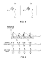
FIG. 3 shows a schematic diagram of the interference from the ambient light source.
FIG. 4 shows a schematic diagram of the denoising method for an image system according to the first embodiment of the present disclosure.
FIG. 5 shows a flow chart of the denoising method for an image system according to the first embodiment of the present disclosure.
FIG. 6 shows another schematic diagram of the image system according to the embodiment of the present disclosure.
FIG. 7 shows a schematic diagram of the denoising method for an image system according to the second embodiment of the present disclosure.
FIG. 8 shows a flow chart of the denoising method for an image system according to the second embodiment of the present disclosure.
DETAILED DESCRIPTION OF THE EMBODIMENT
It should be noted that, wherever possible, the same reference numbers will be used throughout the drawings to refer to the same or like parts.
The present disclosure is related to an image system and a denoising method configured to eliminate interference from external ambient light sources. The ambient light sources have different brightness variation intervals within each brightness variation cycle, and the different brightness variation intervals may be caused by a single ambient light source or by different types of ambient light sources to have a regular or an irregular variation.
Please refer to FIGS. 1 and 2, FIG. 1 shows a schematic diagram of the image system 1 according to an embodiment of the present disclosure; and FIG. 2 shows a schematic diagram of the brightness variation with time of ambient light sources. Although the image system 1 is shown as an optical touch system herein, in other embodiments the image system 1 may be any image system that utilizes at least one image sensor to acquire images and accordingly performs the system control and is not limited to that shown in FIG. 1. In addition, the brightness variation of ambient light sources shown in FIG. 2 is only exemplary.
The image system 1 includes a touch surface 10, at least one image sensor (two image sensors 11 and 12 are shown herein), a light source 13 and a processing unit 14. FIG. 1 further shows an ambient light source 9 in order to represent an operation environment of the image system 1. For example, the ambient light source 9 is shown as a set of fluorescent tubes herein, and each of the fluorescent tubes has a first end 91 and a second end 92. The brightness variation with time of the two ends (i.e. the first end 91 and second end 92) of a fluorescent tube may be similar to that shown in FIG. 2, and the reason causing the non-uniform brightness at two ends of a fluorescent tube is the direction of exciting current in the tube. For example, in the half cycle that the AC current flows from the first end 91 to the second end 92, the first end 91 can have a higher brightness and the second end 92 can have a lower brightness; on the contrary, in the half cycle that the AC current flows from the second end 92 to the first end 91, the first end 91 can have a lower brightness and the second end 92 can have a higher brightness. Therefore, the respective brightness variation of the first end 91 and the second end 92 may be different in two half cycles as shown in FIG. 2. Especially, infrared light irradiated by a fluorescent tube can have apparent non-uniform brightness variations due to different directions of exciting current. The ambient light source 9 may have a brightness variation cycle CL such as ( 1/60) second or ( 1/50) second, wherein a value of the brightness variation cycle CL is determined according to an AC frequency of the power system coupled to the ambient light source 9. In FIG. 2, each of the brightness variation cycles CL includes a first brightness variation interval C1 and a second brightness variation interval C2, wherein the first brightness variation interval C1 and the second brightness variation interval C2 have different brightness values or different brightness variations but have identical time intervals. It is appreciated that although in FIG. 2 an average brightness value of the first brightness variation intervals C1 is shown to be larger than that of the second brightness variation intervals C2, the present disclosure is not limited thereto. For example, in other embodiments the first brightness variation intervals C1 and the second brightness variation intervals C2 may have irregular brightness variations and different time intervals depending on a combination of ambient light sources.
The touch surface 10 may be made of suitable material. A user may use an object, e.g. his or her finger(s) or other touch device, to approach or contact the touch surface 10 in order to perform various controls on the image system 1, wherein functions that can be performed may be those in conventional touch systems such as the cursor control or the item selection, but not limited thereto. Since functions of a touch system is well known, details thereof will not be described herein. The spirit of the present disclosure is to eliminate the impact on the operation accuracy of an image system from complicated brightness variations of ambient light sources similar to FIG. 2.
The image sensors 11 and 12 may be CCD image sensors, CMOS image sensors or the like. Field of views of the image sensors 11 and 12 preferably encompass at least the touch surface 10 in order to acquire images looking across the touch surface 10 and containing at least one object hovering upon or in contact with the touch surface 10. It should be mentioned that a number of the image sensors are not limited to two, and the disposition of the image sensors is not limited to that shown in FIG. 1.
The light source 13 may be any suitable light source such as a light emitting diode (LED), a reflective stripe or an emitting stripe, but not limited thereto. In addition, the disposition and number of the light source 13 is not limited to that shown in FIG. 1. The light source 13 may be disposed at any suitable location or has an arbitrary number as long as the image sensors 11 and 12 may acquire images of at least one object blocking the light irradiated by the light source 13.
The processing unit 14 receives images acquired by the image sensors 11 and 12 and performs post-processing. For example, the processing unit 14 may calculate a displacement or other operating parameters according to an image variation of the object in the acquired images and correspondingly control the program executed by a host 15, wherein the method that the processing unit 14 calculates various operating parameters according to the images acquired by the image sensors 11 and 12 are well known, e.g. calculating the displacement according to the correlation between images, and thus details thereof will not be described herein.
Field of views of the image sensors 11 and 12 may be interfered by ambient light sources. For example, an image of the ambient light source 9 may appear in the images acquired by the image sensors 11 and 12 as shown in FIG. 3. For example, the image sensors 11 and 12 may acquire a first image IC1 in the first brightness variation interval C1, and acquire a second image IC2 in the second brightness variation interval C2 corresponding to a acquisition phase of the first image IC1 in the first brightness variation interval C1, wherein the first image IC1 contains a first ambient light source image I9 and a first object image IO, and the second image IC2 contains a second ambient light source image I9′ and a second object image IO′. If the first brightness variation interval C1 and the second brightness variation interval C2 have identical brightness variations, the processing unit 14 is able to remove the ambient light source images I9 and I9′ by calculating an image difference between the first image IC1 and the second image IC2 and further to calculate a correct displacement between the object images IO and IO′. However, if the brightness variation of the ambient light source 9 is similar to that shown in FIG. 2, the processing unit 14 is unable to eliminate the interference from the ambient light source images I9 and I9′ when calculating the displacement or control parameters using the same method, and thus errors can be introduced. Therefore, the present disclosure further provides a denoising method (described later) to effectively reduce or eliminate the impact of the ambient light source 9 on the image system 1.
Please refer to FIG. 4, it shows a schematic diagram of the denoising method for an image system according to an embodiment of the present disclosure, wherein the ambient light source 9 irradiates at a lighting frequency (1/CL) and has a brightness variation cycle CL, the image sensors 11 and 12 successively acquire two images straight at a sampling frequency (2/CL), and the light source 13 also lights at a lighting frequency (2/CL). In this embodiment, sampling enable signals, such as S1 and S2, are sent to the image sensors 11 and 12 simultaneously such that the image sensors 11 and 12 may successively acquire two images I1 and I2 within each of the brightness variation intervals C1 and C2, wherein a time interval At between the images I1 and I2 should be controlled as short as possible. A light enable signal SL is sent to the light source 13 once within each of the brightness variation intervals C1 and C2 to enable the light source 13, wherein the light enable signal SL is preferable synchronized to one of the sampling enable signals S1 and S2 (e.g. synchronizing to the sampling enable signal S2 herein). In this manner, the image sensors 11 and 12 are able to respectively acquire a dark image I1 (i.e. the light source 13 is turned off) and a bright image I2 (i.e. the light source 13 is turned on) within each of the brightness variation intervals C1 and C2 of the ambient light source 9. The processing unit 14 then calculates an image difference between the dark image I1 and the bright image I2 so as to eliminate the impact from the ambient light source 9, and to further calculate a displacement between the object images IO and IO′. In this embodiment, since the time interval At is very short compared to the brightness variation intervals C1 and C2 of the ambient light source 9, a brightness change of the ambient light source 9 between the time interval At is not apparent, and thus the interference caused by the brightness change of the ambient light source 9 can be significantly reduced by calculating the image difference. In addition, an enable interval tL of the light enable signals SL may be larger than, equal to or smaller than an enable interval t2 (i.e. an exposure time) of the sampling enable signals S2.
Please refer to FIG. 5, it shows a flow chart of the denoising method for an image system according to the first embodiment of the present disclosure including the steps of: using an image sensor to sequentially acquire a first image and a second image within each of the brightness variation intervals (Step S21); lighting a light source once within each of the brightness variation intervals, wherein the lighting of the light source is synchronized to one of the first image and the second image (Step S22); and subtracting the second image or the first image which is not synchronized to the lighting of the light source from the first image or the second image which is synchronized to the lighting of the light source thereby eliminating interference from the ambient light (Step S23); wherein details of every step of this embodiment has been illustrated in FIG. 4 and its corresponding descriptions and thus will not be repeated again.
Please refer to FIG. 6, it shows another schematic diagram of the image system 1′ according to the embodiment of the present disclosure. The main difference between FIG. 6 and FIG. 1 is that the light source 13 in FIG. 6 is composed of a light guide 131 and a point light source 132, wherein the light guide 131 is configured to convert the point light source 132 into a linear light source. The light guide 131 includes an injection surface A1, an ejection surface A2 and a reflection surface A3, wherein light irradiated by the point light source 132 enters the light guide 131 via the injection surface A1 and irradiates from the light guide 131 via the ejection surface A2, and thus the ejection surface A2 preferably faces the touch surface 10. The reflection surface A3 is preferably a mirror surface such that an object O in the range of the touch surface 10 may correspondingly generate an object mirror image O′ with respect to the reflection surface A3. In the image system 1′, when the point light source 132 is turned on, the image sensors 11 and 12 may acquire an object image of the object O blocking the light guide 131; when the point light source 132 is turned off, the image sensors 11 and 12 may acquire object images of the object O and the object mirror image O′.
Please refer to FIGS. 4 and 6 together, as the object mirror image O′ has a relatively longer distance from the image sensors 11 and 12, the object image of the object mirror image O′ acquired by the image sensors 11 and 12 has a lower brightness value, and thus an enable interval t1 (i.e. a first exposure time) of the sampling enable signal S1 may be longer than an enable interval t2 (i.e. a second exposure time) of the sampling enable signal S2 such that the object images in the two images I1 and I2 may have substantially identical brightness values. In other words, in the first embodiment the enable intervals t1 and t2 (i.e. the exposure times) may be identical or different according to different applications.
Please refer to FIG. 7, it shows a schematic diagram of the denoising method for an image system according to the second embodiment of the present disclosure, wherein the ambient light source 9 irradiates at a lighting frequency (1/CL) and has a brightness variation cycle CL, the image sensors 11 and 12 successively acquire an odd number of at least three images straight (e.g. 3, 5, 7, . . . images) at a sampling frequency (2/CL), and the light source 13 also lights at a lighting frequency (2/CL). In this embodiment, an odd number of at least three sampling enable signals, such as S1 to S3, are sent to the image sensors 11 and 12 simultaneously such that the image sensors 11 and 12 may sequentially acquire three images I1 to I3 within each of the brightness variation intervals C1 and C2, wherein a time interval At between the images I1 and I2 and between the images I2 and I3 does not have particular limitation as long as the odd number of at least three images I1 to I3 can be acquired within one brightness variation interval. A light enable signal SL is sent to the light source 13 once within each of the brightness variation intervals C1 and C2 to enable the light source 13, wherein the light enable signal SL is preferable synchronized to a middle sampling enable signal (e.g. S2 herein) of the sampling enable signals S1 to S3. In this manner, the image sensors 11 and 12 are able to respectively acquire a bright image I2 and an even number of dark images, e.g. I1 and I3 herein, within each of the brightness variation intervals C1 and C2 of the ambient light source 9, wherein an acquisition time of the dark image I1 is previous to that of the bright image I2, and an acquisition time of the dark image I3 is later than that of the bright image I2. The processing unit 14 calculates an image difference between the bright image I2 and a sum or an average of the dark images, e.g. I1 and I3 herein, so as to eliminate the impact from the ambient light source 9, and to further calculate a displacement between the object images. In addition, if the image sensors 11 and 12 acquire five or more than five images within one brightness variation intervals, the dark images are preferably averagely acquired before and after one bright image.
In this embodiment, in order to effectively eliminate interference from the ambient light source 9, enable intervals t1 to t3 of the sampling enable signals S1 to S3 (i.e. exposure times) may be designed in several ways.
In one embodiment, in order to simplify the sampling enable signals, the enable intervals t1 to t3 (i.e. exposure times) may be identical. Therefore, the processing unit 14 may first divide a sum of the dark images I1 and I3 (i.e. a sum of gray levels of corresponding pixels of the dark images I1 and I3) by 2 and then subtracts the processed dark image from the bright image when calculating the image difference between the bright image and the dark images, i.e. I2−(I1+I3)/2; therefore, the interference from the ambient light source 9 can then be eliminated. In other embodiments, when more dark images are acquired, e.g. 4, 6, . . . dark images, the processing unit 14 may first divide a sum of all the dark images (i.e. gray levels of corresponding pixels of all the dark images) by an image number of the dark images (i.e. calculating an average of all the dark images) and then subtracts the averaged dark image from the bright image when calculating the image difference between the bright image and the dark images; therefore, the interference from the ambient light source 9 can then be eliminated.
In another embodiment, the enable intervals t1 to t3 (i.e. exposure times) may be different and satisfy a condition (t1+t3)=t2, e.g. t1=t3=t2/2, but not limited thereto. In this manner, as long as a sum of the enable intervals of all the dark images is equal to an enable interval of the bright image, the processing unit 14 still can eliminate the interference from the ambient light source 9 by calculating the image difference between the bright image and a sum of all the dark images, wherein said sum of all the dark images referred herein is a sum of gray values of pixels at corresponding positions in all dark images. In addition, an enable interval tL of the light enable signals SL may also be larger than, equal to or smaller than an enable interval t2 (i.e. an exposure time) of the sampling enable signals S2.
Please refer to FIG. 8, it shows a flow chart of the denoising method for an image system according to the second embodiment of the present disclosure including the steps of: using an image sensor to sequentially acquire an odd number of at least three images within each of the brightness variation intervals (Step S31); lighting a light source once within each of the brightness variation intervals, wherein the lighting of the light source is synchronized to a middle image of the odd number of images (Step S32); and subtracting a sum or an average of the other images which are not synchronized to the lighting of the light source from the middle image which is synchronized to the lighting of the light source thereby eliminating interference from the ambient light source (Step S33), wherein details of every step of this embodiment has been illustrated in FIG. 7 and its corresponding descriptions and thus will not be repeated again.
In addition, the denoising method of the first and second embodiments of the present disclosure may also be applied to the operation under an ambient light having a fixed brightness variation. That is, when the brightness variation of ambient light sources is fixed, the brightness variations of two brightness variation intervals in one brightness variation cycle are identical. In other words, the denoising method of every embodiment of the present disclosure may be configured to effectively reduce the interference from various ambient light sources and is not limited to the example used in the embodiments of the present disclosure.
As mentioned above, conventional image systems are not able to entirely eliminate the impact caused by ambient light sources, especially when the ambient light sources have complicated brightness variations. Therefore, the present disclosure further provides an image system (FIGS. 1 and 6) and denoising method therefor (FIGS. 5 and 8) that may effectively eliminate the flicker caused by ambient light sources having brightness variation intervals with different brightness variations thereby increasing the system accuracy during operation.
Although the disclosure has been explained in relation to its preferred embodiment, it is not used to limit the disclosure. It is to be understood that many other possible modifications and variations can be made by those skilled in the art without departing from the spirit and scope of the disclosure as hereinafter claimed.