US8894050B2 - Methods and apparatus for suspending vehicles - Google Patents
Methods and apparatus for suspending vehicles Download PDFInfo
- Publication number
- US8894050B2 US8894050B2 US12/407,610 US40761009A US8894050B2 US 8894050 B2 US8894050 B2 US 8894050B2 US 40761009 A US40761009 A US 40761009A US 8894050 B2 US8894050 B2 US 8894050B2
- Authority
- US
- United States
- Prior art keywords
- chamber
- shock absorber
- gas
- valve
- travel
- Prior art date
- Legal status (The legal status is an assumption and is not a legal conclusion. Google has not performed a legal analysis and makes no representation as to the accuracy of the status listed.)
- Active, expires
Links
Images


Classifications
-
- F—MECHANICAL ENGINEERING; LIGHTING; HEATING; WEAPONS; BLASTING
- F16—ENGINEERING ELEMENTS AND UNITS; GENERAL MEASURES FOR PRODUCING AND MAINTAINING EFFECTIVE FUNCTIONING OF MACHINES OR INSTALLATIONS; THERMAL INSULATION IN GENERAL
- F16F—SPRINGS; SHOCK-ABSORBERS; MEANS FOR DAMPING VIBRATION
- F16F9/00—Springs, vibration-dampers, shock-absorbers, or similarly-constructed movement-dampers using a fluid or the equivalent as damping medium
- F16F9/06—Springs, vibration-dampers, shock-absorbers, or similarly-constructed movement-dampers using a fluid or the equivalent as damping medium using both gas and liquid
- F16F9/063—Springs, vibration-dampers, shock-absorbers, or similarly-constructed movement-dampers using a fluid or the equivalent as damping medium using both gas and liquid comprising a hollow piston rod
-
- B—PERFORMING OPERATIONS; TRANSPORTING
- B60—VEHICLES IN GENERAL
- B60G—VEHICLE SUSPENSION ARRANGEMENTS
- B60G17/00—Resilient suspensions having means for adjusting the spring or vibration-damper characteristics, for regulating the distance between a supporting surface and a sprung part of vehicle or for locking suspension during use to meet varying vehicular or surface conditions, e.g. due to speed or load
- B60G17/02—Spring characteristics, e.g. mechanical springs and mechanical adjusting means
- B60G17/04—Spring characteristics, e.g. mechanical springs and mechanical adjusting means fluid spring characteristics
- B60G17/048—Spring characteristics, e.g. mechanical springs and mechanical adjusting means fluid spring characteristics with the regulating means inside the fluid springs
-
- F—MECHANICAL ENGINEERING; LIGHTING; HEATING; WEAPONS; BLASTING
- F16—ENGINEERING ELEMENTS AND UNITS; GENERAL MEASURES FOR PRODUCING AND MAINTAINING EFFECTIVE FUNCTIONING OF MACHINES OR INSTALLATIONS; THERMAL INSULATION IN GENERAL
- F16F—SPRINGS; SHOCK-ABSORBERS; MEANS FOR DAMPING VIBRATION
- F16F9/00—Springs, vibration-dampers, shock-absorbers, or similarly-constructed movement-dampers using a fluid or the equivalent as damping medium
- F16F9/32—Details
- F16F9/48—Arrangements for providing different damping effects at different parts of the stroke
- F16F9/486—Arrangements for providing different damping effects at different parts of the stroke comprising a pin or stem co-operating with an aperture, e.g. a cylinder-mounted stem co-operating with a hollow piston rod
-
- B—PERFORMING OPERATIONS; TRANSPORTING
- B60—VEHICLES IN GENERAL
- B60G—VEHICLE SUSPENSION ARRANGEMENTS
- B60G2202/00—Indexing codes relating to the type of spring, damper or actuator
- B60G2202/10—Type of spring
- B60G2202/15—Fluid spring
- B60G2202/152—Pneumatic spring
-
- B—PERFORMING OPERATIONS; TRANSPORTING
- B60—VEHICLES IN GENERAL
- B60G—VEHICLE SUSPENSION ARRANGEMENTS
- B60G2300/00—Indexing codes relating to the type of vehicle
- B60G2300/12—Cycles; Motorcycles
-
- B—PERFORMING OPERATIONS; TRANSPORTING
- B60—VEHICLES IN GENERAL
- B60G—VEHICLE SUSPENSION ARRANGEMENTS
- B60G2500/00—Indexing codes relating to the regulated action or device
- B60G2500/20—Spring action or springs
- B60G2500/206—Variable pressure accumulators for hydropneumatic suspensions
- B60G2500/2064—Variable pressure accumulators for hydropneumatic suspensions by varying the number of accumulators connected in parallel to the hydraulic cylinder
-
- B—PERFORMING OPERATIONS; TRANSPORTING
- B60—VEHICLES IN GENERAL
- B60G—VEHICLE SUSPENSION ARRANGEMENTS
- B60G2500/00—Indexing codes relating to the regulated action or device
- B60G2500/20—Spring action or springs
- B60G2500/22—Spring constant
-
- B—PERFORMING OPERATIONS; TRANSPORTING
- B60—VEHICLES IN GENERAL
- B60G—VEHICLE SUSPENSION ARRANGEMENTS
- B60G2600/00—Indexing codes relating to particular elements, systems or processes used on suspension systems or suspension control systems
- B60G2600/21—Self-controlled or adjusted
Definitions
- Embodiments of the invention generally relate to methods and apparatus for use in vehicle suspension. Particular embodiments of the invention relate to methods and apparatus useful for variable spring rate and/or variable damping rate vehicle suspension.
- Vehicle suspension systems typically include a spring component or components and a damping component or components. Frequently those discrete components are separately mounted on a vehicle.
- mechanical springs such as metal leaf or helical springs, have been used in conjunction with some type of viscous fluid based damping mechanism mounted functionally in parallel.
- compressed gas acting over a piston area has replaced mechanical springs as the spring component in some contemporary suspension systems. While compressed gas springs are usually lighter and more compact than their mechanical counterparts, the compression and expansion curve, and corresponding spring rate, is not linear and becomes particularly exponential beyond a mid range of gas compression.
- FIG. 1 is a graph showing a gas compression curve having such an exponential spring rate in an air shock based upon force and travel.
- the force (corresponding to pressure acting on a given piston area) versus the linear travel or displacement of the air spring is not linear. While the curve approximates linearity during an initial portion of travel, the last portion of travel is exponential. At higher travel values, the rate of increase of the force (pressure) for incrementally further travel is very large and the shock absorber is therefore increasingly more rigid in the last third of its stroke.
- FIG. 3 A gas spring curve associated with the device of FIG. 2 is shown in FIG. 3 .
- the point Q shows that point where the mushroom valve opens and combines the first and second gas chambers.
- Embodiments of the invention generally relate to methods and apparatus for use in vehicle suspension. Particular embodiments of the invention relate to methods and apparatus useful for variable spring rate and/or variable damping rate vehicle suspension.
- a shock absorber for a vehicle includes a gas spring having first and second gas chambers. The first chamber is utilized during a first travel portion of the shock absorber and the first and second chambers are both utilized during a second portion of travel.
- the shock absorber further includes a fluid isolated damper for regulating the speed of travel throughout both portions of travel.
- an adjustment member for initiating commutation between first and second gas chambers in a shock absorber has an adjustable length and is movable as the first chamber is compressed. The adjustment member is movable to a location whereby the member mechanically opens a valve, thereby initiating communication between the gas chambers.
- a method of operating a shock absorber having first and second gas chambers and a fluid isolated damper includes compressing the first chamber to a predetermined volume; initiating communication between the first chamber and the second chamber; further compressing the first chamber; closing the communication path between the chambers; decompressing the first chamber; and regulating the speed of at least one of the compression and decompression of at least the first chamber.
- a method of operating an air shock having two gas chambers includes compressing the first chamber to a predetermined first amount; initiating communication between the first and second chambers; closing communication between the chambers; compressing the first chamber to a predetermined second amount; initiating communication between the first and second chambers; and closing communication between the chambers.
- a Schrader-type valve for filling a first and second air chamber to an equal pressure includes an axially movable stem member depressible to communicate with the first chamber through a first port and further depressible to communicate with the first and second chambers through a second port.
- FIG. 1 shows a typical air spring curve generated by a conventional air spring operating on compressed gas.
- FIG. 2 is a section view of a device that teaches a second gas chamber intended to increase the effective gas volume usable by the air spring.
- FIG. 3 shows an air spring curve generated by the device of FIG. 2 .
- FIG. 4 shows an external view of a vehicle shock absorber embodiment incorporating aspects of the present invention.
- FIG. 5 shows a section view of a shock absorber of FIG. 4 in an extended position and FIG. 5A is an enlarged view of a closed communication valve.
- FIG. 6 shows the shock absorber of FIG. 5 in a retracted position and FIG. 6A is an enlarged view of the communication in an open position.
- FIG. 7 is an air spring curve generated by the shock absorber of FIG. 5 .
- FIG. 8 shows an alternative mechanism for opening the second, or additional, gas chamber of the air shock, the mechanism shown in a closed position.
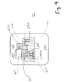
- FIG. 9 shows the mechanism of FIG. 8 in an open position.
- FIG. 10 is a section view showing an adjustable arrangement for selecting a point at which the two gas chambers communicate.
- FIG. 11 is a section view showing a novel Schrader-type valve for filling the gas chambers of the air shock, the valve shown in a closed position.
- FIG. 12 shows the Schrader-type valve of FIG. 11 in a first, open position.
- FIG. 13 shows the Schrader-type valve of FIG. 11 in a second, open position.
- air is used interchangeably with the term “gas” unless otherwise stated. Both terms generally indicate a compressible fluid.
- One embodiment comprises an air spring shock absorber for a vehicle.
- the vehicle is a bicycle.
- the air spring is advantageous because it includes at least two sequentially activated gas spring chambers that operate to increase the effective gas volume of the spring, at least one communication valve for opening a fluid flow path between the chambers, and a fill valve for selectively applying gas pressure within the chambers.
- the fluid path between the chambers is opened using a mechanical actuator and in another embodiment, a pressure actuated valve opens the fluid path between the chambers.
- at least two air chambers can be filled from the same pressure inlet either simultaneously or sequentially as preferred.
- both chambers of a dual gas chamber gas spring can be filled simply in one pressurization step.
- the multiple gas chamber spring can further include and operate in conjunction with a damper.
- the damper comprises a viscous fluid that is isolated from the compressible spring fluid. Separation of the damping fluid from the spring fluid avoids or delays the formation of fluid emulsion during vigorous dynamic mixing of the two fluids. The avoidance of emulsion formation is desirable because emulsified liquids do not function efficiently as damping fluids as compared to relatively pure liquids. Emulsion formation can result in what is known as damping “fade” where the efficiency of a mixed fluid damper diminishes with use. Such viscous fluid may be isolated or distanced from the fluid spring in various ways.
- isolation may be facilitated by a barrier, by gravity or by a tortuous path.
- a relevant feature of the isolation mechanism is that the damping fluid and the spring fluid are not co-located in the in the same dynamic volume. By providing some degree of isolation or separation between the damping and spring fluids, which are often liquid and gas respectively, the formation of emulsion is avoided or greatly delayed.
- the combined versatility of an adjustable or “tunable” damper and the multi-chamber spring result in a shock absorber having a selectively variable force versus travel versus velocity curve (e.g. 3-d surface as plotted).
- the multi-chamber air spring is utilized to improve the overall performance of a shock absorber having a damper with automatic “blow off” features.
- a piston in cylinder type suspension gas spring preferably includes enough gas volume so that the gas compression curve, for a corresponding suspension system, remains substantially linear over a portion of the stroke (e.g. first 2 ⁇ 3rds) of the suspension system.
- the initial gas pressure in a gas spring shock absorber must be set high to yield a usable shock absorber (e.g. one that isn't too soft). Unfortunately such a shock absorber, as it is compressed, becomes quickly very stiff and allows little “settle” or “sag” when the shock initially loaded.
- Embodiments described herein extend the substantially linear portion of the spring rate curve beyond that represented by the single chamber curve of FIG. 1 and therefore allow for higher initial pressure settings without overly accelerating the onset of unusable stiffness during compression.
- FIG. 4 an external view of a gas spring vehicle shock absorber, optionally a rear bicycle shock absorber, is shown.
- the embodiment includes a damper body 100 having a lower mounting eye 105 preferably connected to an end thereof.
- the damper body 100 is telescopically disposed within an air sleeve 110 such that movement of the damper body 100 in and out of the air sleeve 110 , against air pressure internal to the sleeve 110 , compensates for, or absorbs, disparities in the terrain being traversed by the bicycle.
- the air sleeve 110 includes an upset 115 corresponding to an internal by-pass port that allows pressure to equalize across a gas compression piston, carried by an upper end of the damper body 100 , as the piston passes the recess, corresponding to the upset 115 , in the internal surface of the air sleeve 110 .
- An upper portion of the air sleeve 110 includes a gas fill valve (inlet and bleed) 125 which may typically be a Schrader-type valve or any other suitable valve mechanism.
- the upper portion of the air sleeve 110 also includes an upper mounting eye 130 .
- the rear bicycle shock absorber of FIG. 4 also includes a damper stiffness adjustment lever and knob assembly 135 (including “blow off” adjustment) for adjusting damping characteristics of the shock absorber.
- FIG. 5 shows a cut away view of the shock absorber of FIG. 4 and its corresponding internal parts.
- the shock absorber is shown in a fully extended position.
- a damper body 100 is hollow and contains a floating piston 140 moveably disposed therein.
- the floating piston 140 divides the interior of the damper body 100 into a compensator gas chamber 145 and a compression damping fluid chamber 150 .
- the compensator gas chamber 145 volume is reduced, by downward movement of the floating piston 140 , in proportion to the volume of the damper support shaft 155 that enters the rebound damping fluid chamber 160 (not visible in the extended position) as the damper body 100 moves telescopically into the air sleeve 110 during the compression of the shock absorber.
- U.S. Pat. Nos. 6,105,988 and 6,311,962 show a structure of a gas spring and damper assembly and U.S. Pat. No. 6,360,857 shows a structure of a damper having some adjustable features and each of those patents are incorporated herein, in their entirety by reference.
- a communication valve 185 is disposed at the upper end of a communication valve shaft 167 .
- the valve which is normally closed due to a biasing member or spring 169 , opens upon the application of an axial force to shaft 167 , to allow communication between the first gas chamber 165 and a second gas spring chamber 170 .
- the axial force is supplied by contact with the moving compression piston 160 .
- Valve 185 with its seal ring 187 blocking a fluid path through the valve seat, is shown in FIG. 5A .
- the gas pressure in the first gas spring chamber 165 continues to increase until the top of the gas compression piston 160 impinges upon the lower end of a communication valve shaft 167 .
- This position of the communication valve shaft 167 is illustrated in FIG. 6 , showing the shock absorber of FIG. 5 in a retracted position and wherein a second gas spring chamber 170 is exposed to the first chamber.
- the force exerted by the gas compression piston 160 on the lower end of the communication valve shaft 167 moves valve member 185 off of a valve seat 186 , thereby opening a fluid flow path through valve seat 186 and between the first gas spring chamber 165 and the second gas spring chamber 170 .
- any pressure differential between the chambers equalizes.
- the effective volume of the shock absorber gas spring is increased over the volume of the first gas spring chamber 165 by the volume of the second gas spring chamber 170 .
- the flow path between the chambers 165 , 170 may provide open fluid communication such that pressure loss through the flow path is minimal or negligible at typical compression/rebound velocities of the damper body 100 .
- variables that can be varied in order to derive a preferred travel versus pressure (i.e. force) profile, or “spring rate” profile over the range of travel.
- Variables that may be selectively altered include: length and diameter of the first chamber 165 , volume of the second chamber 170 , initial pressure state of the first chamber 165 , initial pressure state of the second chamber 170 and length and/or position of the communication valve shaft 167 .
- piston areas of a pressure divider and initial check valve spring load may be varied.
- the initial pressure state and the diameter of the first chamber 165 define the shape of the travel versus spring pressure profile for the shock absorber prior to opening the communication valve 185 .
- the location, along the travel, of the opening of the valve 185 determines when the spring force/travel curve of the first chamber alone is altered and combined characteristically with the second, or additional, chamber(s).
- the values chosen for those variables result in a substantially linear spring rate prior to, and following, fluid communication between the chambers 165 , 170 .
- the initial pressure in the second chamber 170 is set to equal a pre-calculated pressure in the first chamber 165 corresponding to a point just before the gas compression piston 160 contacts the lower end of the communication valve shaft 167 .
- the initial pressure in the second chamber 170 may be set at the same pressure (and time) as the initial (fully extended) pressure in the first chamber 165 .
- the volume of the first chamber 165 is reduced and the pressure in the first chamber rises until the communication valve 185 is opened.
- the second chamber pressure is still at its initial (and now lower) pressure setting, fluid flows from the first chamber 165 , through the communication valve 185 and into the second chamber 170 when valve 185 is opened.
- the pressure in the now-combined first and second chambers equalizes at a pressure value somewhere between the pre-communication first chamber pressure and the initial second chamber pressure (the equalization pressure depends on the relative volumes of the first and second chambers and the first chamber displacement that occurs prior to equalization).
- the slope of the force versus travel graph (based on effective spring rate) for the forgoing arrangement, both before and after the valve 185 opens is exemplified as illustrated in the curve of FIG. 7 .
- the second chamber 170 retains the compression pressure of the first chamber 165 as a set point and no further equalization occurs upon opening of the communication valve 185 .
- a one-way valve e.g., check valve
- a one-way valve is included between the chambers and permits communication from the second to the first chamber. In this manner, compressed air is allowed to escape from the second to the first chamber upon extension of the shock absorber, thereby resetting the second chamber to a lower pressure, the pressure determined by the characteristics of a spring-biased valve (e.g. higher spring bias equals greater retained differential pressure where lower bias equals more equalization), for example.
- the communication valve shaft 167 is available in different lengths. A user may install a longer length valve shaft 167 for communication earlier in the shock compression stroke or a shorter length for communication later in the shock stroke.
- the communication valve 185 and shaft 167 are not coaxial with the center line of the shock absorber, thereby allowing the damper support shaft 155 to be coaxially located.
- the damper support shaft includes control mechanisms through or around the shaft 155 for selectively adjusting and/or blocking valves or orifices of the damper assembly to effect changes in damping rates, lock-out and/or blow-off of the damper.
- the damper assembly is preferably mounted on a coaxial (with the damper body) shaft to minimize any bending and binding of the damping piston assembly (created by asymmetric damping fluid induced forces) during use.
- the eccentric placement of the communication valve 185 and shaft 167 allows isolation of the damping fluid (e.g.
- damping fade i.e. intermingling of spring gas and damping liquid where the emulsion reduces the effectiveness of the liquid phase as a damping medium
- the shock absorber shown in the Figures illustrates such an isolated arrangement including a floating piston/gas chamber compensated damping system.
- a pressure divider 200 may be used in lieu of, or together with, the communication valve 185 and communication valve shaft 167 to facilitate selective tailoring of the spring rate curve (i.e. communicating between first and second chambers 165 , 170 ).
- the pressure divider is disposed to maintain a known differential pressure between the first 165 and second 170 chambers upon opening of a valve therebetween.
- the divider includes a moveable assembly 210 with two opposing, outwardly facing piston surfaces. A first piston surface 205 is exposed to the first chamber 165 and a second piston surface 220 is exposed to the second chamber 170 .
- the area of the second piston surface 220 is larger than the area of the first piston surface 205 .
- the divider 200 additionally includes a normally closed, spring-biased pressure relief valve 230 designed to permit fluid communication from the second 170 to the first chamber 165 while normally checking flow in the reverse direction.
- FIG. 8 shows the divider prior to actuation.
- the piston 220 facing the second chamber 170 because of its relatively large surface, keeps the piston assembly 210 biased towards the first chamber 165 .
- the pressure relief valve 230 remains closed as there is insufficient pressure to cause it to act against its biasing spring.
- FIG. 9 shows the valve assembly upon actuation, which is brought about by compression of the first chamber 165 to a point wherein the difference in surface area of the pistons 205 , 220 is overcome by the increased pressure in the first chamber 165 and the piston assembly is moved towards the second chamber 170 .
- a radially extending lip 215 disposed about the perimeter of smaller piston side of the piston assembly 210 upsets the pressure relief valve 230 and pushes it laterally off of its seat.
- the pressure relief valve permits gas to travel through it in a reverse direction (i.e. normally checked direction from the primary 165 to the secondary 170 gas chamber).
- the pressure relief valve 232 is a laterally actuated valve but does not have a check function and thereby permits the second chamber to remain at its higher pressure after communication between the chambers has ceased. In this embodiment, flow of air into the second chamber is still possible through a valve, such as a laterally actuated gate valve, that becomes offset by the lip 215 , but flow from the second chamber is prevented.
- the pressure divider 200 is shown having a 2:1 area ratio. However, any suitable ratio may be used, (by providing suitably sized piston areas), in order to facilitate the maintenance of desired differential pressures.
- the piston area of 220 is smaller than the piston area of 205 and the chambers are not communicated until very late in the travel corresponding to a high pressure in the primary chamber.
- the spring rate of the spring 232 , and its initial state of compression, versus the seal area of the valve 230 dictate how much pressure bleed from the second chamber 170 to the first chamber 165 occurs as the shock rebounds from a compression stroke.
- the spring is set so that the second chamber 170 retains a portion of the compression pressure corresponding to a selected amount of compression travel where the gas compression curve for the first chamber 165 is beginning to turn significantly exponentially higher.
- the check valve spring initial set load by allowing retention of a given amount of the previous compression stroke, correspondingly allows the total force versus travel curve to exhibit a smoother transition upon communication of the two chambers 165 , 170 .
- the volume 235 shown in the Figures represents a volume that may be vented to atmosphere. In any case, the volume is such that any increase in pressure as the piston assembly shifts will not adversely effect the operation of the pressure divider.
- the screw 223 and o-ring 222 serve to seal port 224 which communicates with volume 235 .
- the piston assembly 210 without the screw 223 and o-ring 222 , may be inserted into the pressure divider and gas trapped in 235 may vent so that the piston may be easily inserted.
- screw 223 and o-ring 222 are installed thereby sealing volume 235 .
- the air spring is intended in some embodiments to be utilized in a shock absorber system that includes a damper and the operation of the first and secondary chambers permit the damper to operate in its most effective way over the course of the shock's operation.
- a damper is most effective during the linear part of the gas spring curve when, depending upon the speed at which the shock is operating, the damper meters fluid from one side of a piston assembly to the other, effectively absorbing (ultimately converting it to heat and dissipating it) energy.
- the damper provides less or virtually no damping action since the shock has become so stiff that movement of the shock is limited and the damper is unable to meter significant fluid.
- the dual chamber arrangement described herein permits the linear portion of the spring curve to continue through a greater range of shock travel and delays the less desirable non-linear portion, thereby resulting in an improved overall shock absorber function including damping.
- the shock includes a damper lock which substantially prevents fluid transfer from taking place within a portion of the damper.
- the lock is configured so that the damper becomes substantially rigid when the fluid transfer path is blocked.
- Such a feature allows a user to selectively lock the shock into a substantially rigid configuration in order to minimize “pedal bob” or other vehicle power dissipation due to unwanted shock compression under power. Even when locked there is the possibility that a disparity in the terrain will require activation of the shock to prevent damage to the shock and/or vehicle. For that reason the shock having a damper lock as described may also be equipped with a blow off feature.
- One such damper lock/blow off feature is described in U.S. Pat. No. 7,163,222 which patent is incorporated herein by reference in its entirety.
- the dual chamber air spring is used with a damper having an adjustable blow-off feature.
- the blow off feature is an automatic override permitting the damper in a “locked out” shock absorber to operate and meter fluid if subjected to a rapid shock event, like a sudden, abrupt bump in a road.
- a suddenly operated or “blown off” damper will be more likely to be operating in a linear portion of the spring curve.
- FIG. 10 shows generally a pressure containing bulkhead 250 that is sealed in a nut 255 by a pair of O-rings 260 , 265 .
- the bulkhead also includes a Schrader valve assembly 125 and is retained axially and rotationally within the nut by a key member 270 .
- the nut is shown in an uppermost position and axially abutted relative to the upper housing that includes secondary chamber 170 .
- a gap 175 is located between the bulkhead 250 and the lower housing so that relative movement may occur before axial abutment between the bulkhead and the housing.
- Mating threads 275 , 276 are cut in a same direction (e.g. both are right handled threads) and have the same pitch and major/minor diameter.
- the gap 175 closes and an axial space or gap correspondingly forms between the nut 255 and the upper housing. In this manner, the bulkhead 250 is effectively moved downward relative to the lower housing, thereby reducing the volume of the first chamber 165 and ensuring the second chamber 170 will be opened at an earlier point in the travel of the shock during a compression stroke.
- the communication valve 185 and valve shaft 167 and valve seat 186 are designed to be axially adjustable relative to the bulkhead 250 .
- the valve 185 may be seated in an axially movable tubular shaped seat (not shown) that is sealed by a circumferential o-ring (not shown) between the seat body and the bore and axially movable relative to a bore (not shown) in the bulkhead.
- the seat may have a cage (not shown) extending upwardly, toward the second chamber, there from where the cage culminates in a threaded nut (not shown) having a center axis substantially coincident with a center axis of the valve and seat.
- the cage and nut are positioned from the valve such that there is ample space to accommodate axial movement of the valve up into a volume surrounded by the cage and upwardly bounded by the nut.
- a knob (not shown) for manipulation is installed at an upper end of the shock absorber. The knob is connected to a shaft (not shown), threaded at a lower end thereof, where a smooth portion of the threaded shaft extends through an upper wall of the second chamber and is sealed there through by a seal (e.g.
- the knob and the shaft are substantially coaxial with the valve and seat and the shaft is threadedly engaged with the nut.
- the shaft does not obstruct upward movement of the valve relative to the seat.
- Rotation (by a user for example) of the knob in turn rotates the shaft which in turn causes the shaft to turn within the nut.
- the nut is raised or lowered depending on the sense of the threads of the engaged shaft and nut and the direction of rotation. As the nut is raised or lowered such axial motion is transmitted through the cage to the seat and valve.
- the knob can be turned by a user and through the use of axial movement transmitted by threads, the knob permits the valve and shaft and valve seat to be raised relative to the bulkhead.
- the shaft is effectively shortened and the lower end of the shaft will come into contact with the piston surface 160 later in the compression stroke, thereby extending the length of the stroke prior to the opening of the second chamber.
- a valve/seat combination in a raised position may be lowered by turning the knob thereby causing the communication to occur earlier in the compression stroke.
- the first 165 and second 170 chambers are filled by introducing pressure, from a suitable gas pump or other source of pressurized gas, into the gas fill valve 125 .
- the gas fill valve comprises a Schrader-type valve as shown in FIGS. 11-13 .
- the valve 300 is designed to fill both of the primary and secondary chambers with pressurized gas from the single valve body 310 . In FIG. 11 , the valve is closed with no communication of air therethrough.
- a valve stem 320 is connected through a valve core 325 to a primary fill valve 330 such that axial movement of the spring loaded valve stem 320 causes an opening of the primary fill valve 330 and axial movement of a valve pusher stem 335 .
- Sufficient axial movement of the valve pusher stem 335 closes a gap 340 until the valve pusher stem 335 contacts the second chamber fill valve stem 345 .
- further movement of the valve pusher stem 335 moves the second chamber fill valve stem 345 and correspondingly separates the second chamber fill valve 350 from a valve seat.
- the design ensures that sufficient axial movement of the valve stem 320 opens the primary fill valve 330 and further movement of the valve stem subsequently opens the second chamber fill valve 350 .
- FIG. 12 illustrates the Schrader-type valve with the valve stem 320 depressed and primary fill valve 330 open. In this position, pressurized air communicates through the valve 330 and to exit 360 formed in valve body 310 which preferably leads to the first gas chamber of a shock absorber.
- FIG. 13 illustrates the Schrader-type valve with valve 330 open and gap 340 closed. Further, the second chamber fill valve stem 345 has been axially depressed to open secondary chamber fill valve 350 . With the components of the Schrader-type valve in the position shown in FIG. 13 , the first and second chambers can be filled simultaneously. Gap 340 can be sized to determine operative characteristics of the valve 300 . For example, a gap of 0.050′′ in one embodiment leaves a gap of sufficient width that second chamber is not inadvertently filled along with the first chamber.
- the valve stem 320 may be moved either mechanically, by a probe on a pressure fitting (not shown) of a pressurized gas source, or solely by the introduction of pressurized gas into the fill valve body 310 wherein the pressurized gas acts over the surface area (i.e. piston area) of the primary fill valve 330 .
- the dimension of the gap 340 is set such that movement of the valve stem 320 and primary fill valve 330 , caused solely by the introduction of pressure, is not sufficient under normal operating pressures to close the gap 340 between the valve pusher stem 335 and the secondary chamber fill valve stem 345 .
- only the primary fill valve 330 is opened allowing pressurized gas to be introduced through primary passage 355 and into the first chamber 165 .
- Such movement sufficient to close the gap and open secondary chamber fill valve 350 may be induce by a gas fill fitting (not shown) connected to the fill gas pressure source and having a protrusion or “stinger” in it that is dimensioned to move the valve stem a sufficient distance to close the gap and open the secondary chamber fill valve.
- a fitting may be used without a stinger and the valve stem 320 may be moved by gas pressure from the fill gas pressure source.
- the respective porting of the valve assembly can be reversed (not shown) so that initial movement of the valve stem opens the second chamber and further movement closes the gap and opens the primary chamber.
- a mechanical probe attached to a pressure hose fitting (not shown) for example, is used to move the valve stem 320 .
- the length of the probe is sufficient to open the primary fill valve 330 , close the gap 340 , cause movement of the valve pusher stem 335 and secondary chamber fill valve stem 345 and thereby open the secondary chamber fill valve 350 .
- pressurized gas flows into the first chamber 165 as previously described and also through the open secondary chamber fill valve 350 , permitting flow into the second chamber 170 .
- the fill valve and shock absorber shown in the Figures herein include o-ring seals as shown and where appropriate. Any suitable seals may be used and seals may be used where not shown or omitted even though shown in any case as appropriate for the channeling and retention of pressurized fluids.
- first and second chambers While the invention has been described with only a first and second chambers, it will the invention can be used with three or more separate chambers, each designed to operate together in a sequential fashion.
- a first chamber could be operable to communicate with a second chamber via the communication valve shaft shown in FIGS. 5 and 6 and the secondary chamber could be operable to communicate with the third chamber via the pressure divider illustrated in FIGS. 8 and 9 .
Landscapes
- Engineering & Computer Science (AREA)
- General Engineering & Computer Science (AREA)
- Mechanical Engineering (AREA)
- Fluid-Damping Devices (AREA)
Abstract
Description
Claims (15)
Priority Applications (27)
| Application Number | Priority Date | Filing Date | Title |
|---|---|---|---|
| US12/407,610 US8894050B2 (en) | 2008-03-19 | 2009-03-19 | Methods and apparatus for suspending vehicles |
| US12/509,258 US8869959B2 (en) | 2008-07-24 | 2009-07-24 | Vehicle suspension damper |
| EP12174239.9A EP2538108B1 (en) | 2008-07-24 | 2009-07-24 | Vehicle suspension damper |
| EP09166412.8A EP2148112B1 (en) | 2008-07-24 | 2009-07-24 | Vehicle suspension damper |
| US12/717,867 US20100244340A1 (en) | 2008-03-19 | 2010-03-04 | Methods and apparatus for combined variable damping and variable spring rate suspension |
| US13/005,474 US9156325B2 (en) | 2008-03-19 | 2011-01-12 | Methods and apparatus for vehicle suspension having multiple gas volumes |
| US13/751,879 US9150075B2 (en) | 2008-03-19 | 2013-01-28 | Methods and apparatus for suspending vehicles |
| US14/271,091 US9186950B2 (en) | 2008-03-19 | 2014-05-06 | Methods and apparatus for combined variable damping and variable spring rate suspension |
| US14/502,679 US9188188B2 (en) | 2008-07-24 | 2014-09-30 | Vehicle suspension damper |
| US14/849,143 US9656531B2 (en) | 2008-03-19 | 2015-09-09 | Methods and apparatus for suspending vehicles |
| US14/848,947 US9855812B2 (en) | 2008-03-19 | 2015-09-09 | Methods and apparatus for vehicle suspension having multiple gas volumes |
| US14/854,805 US9797467B2 (en) | 2008-03-19 | 2015-09-15 | Methods and apparatus for combined variable damping and variable spring rate suspension |
| US14/931,259 US9688347B2 (en) | 2008-07-24 | 2015-11-03 | Vehicle suspension damper |
| US15/597,875 US10315482B2 (en) | 2008-03-19 | 2017-05-17 | Methods and apparatus for suspending vehicles |
| US15/631,655 US10221914B2 (en) | 2008-07-24 | 2017-06-23 | Vehicle suspension damper |
| US15/788,711 US10408295B2 (en) | 2008-03-19 | 2017-10-19 | Methods and apparatus for combined variable damping and variable spring rate suspension |
| US15/828,230 US10384509B2 (en) | 2008-03-19 | 2017-11-30 | Methods and apparatus for vehicle suspension having multiple gas volumes |
| US16/287,860 US10612618B2 (en) | 2008-07-24 | 2019-02-27 | Vehicle suspension damper |
| US16/395,012 US10618369B2 (en) | 2008-03-19 | 2019-04-25 | Methods and apparatus for suspending vehicles |
| US16/453,474 US11312203B2 (en) | 2008-03-19 | 2019-06-26 | Methods and apparatus for vehicle suspension having multiple gas volumes |
| US16/564,535 US11181163B2 (en) | 2008-03-19 | 2019-09-09 | Methods and apparatus for combined variable damping and variable spring rate suspension |
| US16/840,803 US11041537B2 (en) | 2008-07-24 | 2020-04-06 | Vehicle suspension damper |
| US16/844,762 US11370261B2 (en) | 2008-03-19 | 2020-04-09 | Methods and apparatus for suspending vehicles |
| US17/346,710 US20210301899A1 (en) | 2008-07-24 | 2021-06-14 | Vehicle suspension damper |
| US17/532,334 US20220082150A1 (en) | 2008-03-19 | 2021-11-22 | Methods and apparatus for combined variable damping and variable spring rate suspension |
| US17/723,215 US11951793B2 (en) | 2008-03-19 | 2022-04-18 | Methods and apparatus for vehicle suspension having multiple gas volumes |
| US17/849,214 US20220324284A1 (en) | 2008-03-19 | 2022-06-24 | Methods and apparatus for suspending vehicles |
Applications Claiming Priority (3)
| Application Number | Priority Date | Filing Date | Title |
|---|---|---|---|
| US3801508P | 2008-03-19 | 2008-03-19 | |
| US15754109P | 2009-03-04 | 2009-03-04 | |
| US12/407,610 US8894050B2 (en) | 2008-03-19 | 2009-03-19 | Methods and apparatus for suspending vehicles |
Related Parent Applications (2)
| Application Number | Title | Priority Date | Filing Date |
|---|---|---|---|
| US12/509,258 Continuation-In-Part US8869959B2 (en) | 2008-03-19 | 2009-07-24 | Vehicle suspension damper |
| US12/717,867 Continuation-In-Part US20100244340A1 (en) | 2008-03-19 | 2010-03-04 | Methods and apparatus for combined variable damping and variable spring rate suspension |
Related Child Applications (4)
| Application Number | Title | Priority Date | Filing Date |
|---|---|---|---|
| US12/509,258 Continuation-In-Part US8869959B2 (en) | 2008-03-19 | 2009-07-24 | Vehicle suspension damper |
| US12/717,867 Continuation-In-Part US20100244340A1 (en) | 2008-03-19 | 2010-03-04 | Methods and apparatus for combined variable damping and variable spring rate suspension |
| US13/005,474 Continuation-In-Part US9156325B2 (en) | 2008-03-19 | 2011-01-12 | Methods and apparatus for vehicle suspension having multiple gas volumes |
| US13/751,879 Continuation-In-Part US9150075B2 (en) | 2008-03-19 | 2013-01-28 | Methods and apparatus for suspending vehicles |
Publications (2)
| Publication Number | Publication Date |
|---|---|
| US20090236807A1 US20090236807A1 (en) | 2009-09-24 |
| US8894050B2 true US8894050B2 (en) | 2014-11-25 |
Family
ID=41088091
Family Applications (1)
| Application Number | Title | Priority Date | Filing Date |
|---|---|---|---|
| US12/407,610 Active 2030-10-22 US8894050B2 (en) | 2008-03-19 | 2009-03-19 | Methods and apparatus for suspending vehicles |
Country Status (1)
| Country | Link |
|---|---|
| US (1) | US8894050B2 (en) |
Cited By (22)
| Publication number | Priority date | Publication date | Assignee | Title |
|---|---|---|---|---|
| US9150075B2 (en) | 2008-03-19 | 2015-10-06 | Fox Factory, Inc. | Methods and apparatus for suspending vehicles |
| US9688347B2 (en) | 2008-07-24 | 2017-06-27 | Fox Factory, Inc. | Vehicle suspension damper |
| US9797467B2 (en) | 2008-03-19 | 2017-10-24 | Fox Factory, Inc. | Methods and apparatus for combined variable damping and variable spring rate suspension |
| US10099743B2 (en) * | 2013-12-23 | 2018-10-16 | Dt Swiss Inc. | Suspension control system for a bicycle, bicycle, and suspension control method |
| US10145436B2 (en) * | 2015-12-04 | 2018-12-04 | Eko Sport, Inc. | Rear suspension having an air component and an oil component |
| US10384509B2 (en) | 2008-03-19 | 2019-08-20 | Fox Factory, Inc. | Methods and apparatus for vehicle suspension having multiple gas volumes |
| US10479503B2 (en) * | 2018-02-08 | 2019-11-19 | Vita Inclinata Technologies, Inc. | Suspended load stability systems and methods |
| US10507920B2 (en) * | 2015-05-18 | 2019-12-17 | Sikorsky Aircraft Corp. | Systems and methods for lifting body vibration control |
| US10544850B2 (en) | 2015-11-09 | 2020-01-28 | Itt Manufacturing Enterprises Llc | Viscous damper assembly having lockout function |
| US10870558B2 (en) | 2018-02-08 | 2020-12-22 | Vita Inclinata Technologies, Inc. | Integrated suspended load control apparatuses, systems, and methods |
| US11008198B2 (en) | 2019-07-21 | 2021-05-18 | Vita Inclinata Technologies, Inc | Hoist and deployable equipment apparatus, system, and method |
| US11142433B2 (en) | 2018-02-08 | 2021-10-12 | Vita Inclinata Technologies, Inc. | Bidirectional thrust apparatus, system, and method |
| US11548345B1 (en) | 2020-09-02 | 2023-01-10 | Afco Performance Group, Llc | Suspension component for utility vehicles |
| US11584187B2 (en) | 2019-06-20 | 2023-02-21 | The Dynamic Engineering Solution Pty Ltd | Vehicle suspension system |
| US11618566B1 (en) | 2019-04-12 | 2023-04-04 | Vita Inclinata Technologies, Inc. | State information and telemetry for suspended load control equipment apparatus, system, and method |
| US11620597B1 (en) | 2022-04-29 | 2023-04-04 | Vita Inclinata Technologies, Inc. | Machine learning real property object detection and analysis apparatus, system, and method |
| US11746951B2 (en) | 2019-02-26 | 2023-09-05 | Vita Inclinata Ip Holdings Llc | Cable deployment apparatus, system, and methods for suspended load control equipment |
| US11834174B2 (en) | 2018-02-08 | 2023-12-05 | Vita Inclinata Ip Holdings Llc | Control of drone-load system method, system, and apparatus |
| US11834305B1 (en) | 2019-04-12 | 2023-12-05 | Vita Inclinata Ip Holdings Llc | Apparatus, system, and method to control torque or lateral thrust applied to a load suspended on a suspension cable |
| US11926415B2 (en) | 2018-02-08 | 2024-03-12 | Vita Inclinata Ip Holdings Llc | Long line loiter apparatus, system, and method |
| US11945697B2 (en) | 2018-02-08 | 2024-04-02 | Vita Inclinata Ip Holdings Llc | Multiple remote control for suspended load control equipment apparatus, system, and method |
| US11992444B1 (en) | 2023-12-04 | 2024-05-28 | Vita Inclinata Ip Holdings Llc | Apparatus, system, and method to control torque or lateral thrust applied to a load suspended on a suspension cable |
Families Citing this family (49)
| Publication number | Priority date | Publication date | Assignee | Title |
|---|---|---|---|---|
| US7806390B2 (en) * | 2005-11-29 | 2010-10-05 | Dt Swiss, Inc. | Spring system, in particular for bicycles |
| US9033122B2 (en) | 2009-01-07 | 2015-05-19 | Fox Factory, Inc. | Method and apparatus for an adjustable damper |
| US10060499B2 (en) | 2009-01-07 | 2018-08-28 | Fox Factory, Inc. | Method and apparatus for an adjustable damper |
| US8627932B2 (en) | 2009-01-07 | 2014-01-14 | Fox Factory, Inc. | Bypass for a suspension damper |
| US11306798B2 (en) | 2008-05-09 | 2022-04-19 | Fox Factory, Inc. | Position sensitive suspension damping with an active valve |
| US20100170760A1 (en) | 2009-01-07 | 2010-07-08 | John Marking | Remotely Operated Bypass for a Suspension Damper |
| US8857580B2 (en) | 2009-01-07 | 2014-10-14 | Fox Factory, Inc. | Remotely operated bypass for a suspension damper |
| US9452654B2 (en) | 2009-01-07 | 2016-09-27 | Fox Factory, Inc. | Method and apparatus for an adjustable damper |
| US10047817B2 (en) | 2009-01-07 | 2018-08-14 | Fox Factory, Inc. | Method and apparatus for an adjustable damper |
| US8393446B2 (en) | 2008-08-25 | 2013-03-12 | David M Haugen | Methods and apparatus for suspension lock out and signal generation |
| US9422018B2 (en) | 2008-11-25 | 2016-08-23 | Fox Factory, Inc. | Seat post |
| US9140325B2 (en) | 2009-03-19 | 2015-09-22 | Fox Factory, Inc. | Methods and apparatus for selective spring pre-load adjustment |
| US10036443B2 (en) | 2009-03-19 | 2018-07-31 | Fox Factory, Inc. | Methods and apparatus for suspension adjustment |
| EP4039342A1 (en) | 2008-11-25 | 2022-08-10 | Fox Factory, Inc. | Methods and apparatus for virtual competition |
| US11299233B2 (en) | 2009-01-07 | 2022-04-12 | Fox Factory, Inc. | Method and apparatus for an adjustable damper |
| US10821795B2 (en) | 2009-01-07 | 2020-11-03 | Fox Factory, Inc. | Method and apparatus for an adjustable damper |
| US9038791B2 (en) | 2009-01-07 | 2015-05-26 | Fox Factory, Inc. | Compression isolator for a suspension damper |
| US8936139B2 (en) | 2009-03-19 | 2015-01-20 | Fox Factory, Inc. | Methods and apparatus for suspension adjustment |
| US8807542B2 (en) | 2009-06-05 | 2014-08-19 | Fox Factory, Inc. | Apparatus and methods for a vehicle shock absorber |
| EP2312180B1 (en) | 2009-10-13 | 2019-09-18 | Fox Factory, Inc. | Apparatus for controlling a fluid damper |
| US8672106B2 (en) | 2009-10-13 | 2014-03-18 | Fox Factory, Inc. | Self-regulating suspension |
| DE102009058847B4 (en) * | 2009-12-18 | 2012-09-13 | Thomas Ripa | Hydropneumatic strut for a bicycle |
| US10697514B2 (en) | 2010-01-20 | 2020-06-30 | Fox Factory, Inc. | Remotely operated bypass for a suspension damper |
| US8511448B2 (en) | 2010-02-01 | 2013-08-20 | Trek Bicycle Corp. | Bicycle air shock assemblies with tunable suspension performance |
| EP2402239B1 (en) | 2010-07-02 | 2020-09-02 | Fox Factory, Inc. | Adjustable seat post |
| US8480064B2 (en) | 2010-07-09 | 2013-07-09 | Specialized Bicycle Components, Inc. | Bicycle with suspension |
| US8899560B2 (en) * | 2011-02-16 | 2014-12-02 | Elite Suspension Systems, Llc | Springless combination shock absorber and suspension apparatus, and method of use |
| EP3636953B1 (en) | 2011-05-31 | 2023-09-27 | Fox Factory, Inc. | Apparatus for position sensitive and/or adjustable suspension damping |
| EP2567839B1 (en) | 2011-09-12 | 2019-03-13 | Fox Factory, Inc. | Methods and apparatus for suspension set up |
| US8740237B2 (en) | 2011-09-23 | 2014-06-03 | Specialized Bicycle Components, Inc. | Bicycle with suspension |
| US11279199B2 (en) | 2012-01-25 | 2022-03-22 | Fox Factory, Inc. | Suspension damper with by-pass valves |
| US8770592B2 (en) * | 2012-02-03 | 2014-07-08 | Fox Factory, Inc. | Suspension with hydraulic preload adjust |
| US10330171B2 (en) | 2012-05-10 | 2019-06-25 | Fox Factory, Inc. | Method and apparatus for an adjustable damper |
| DE102012214569B3 (en) * | 2012-08-16 | 2013-10-31 | Ford Global Technologies, Llc | Self-pumping air spring- and damper unit for height adjustment of vehicle body relative to wheel suspension of vehicle, has connecting valve and throttle valve, particularly switchable valves, where working space is aerated to atmosphere |
| US8991841B2 (en) | 2012-09-04 | 2015-03-31 | Msi Defense Solutions, Llc | Air spring, air strut and air suspension system with a linearized spring rate |
| US20140291085A1 (en) * | 2013-03-30 | 2014-10-02 | Ronald Scott Bandy | Segmented Air Shock |
| US9518630B2 (en) | 2013-08-01 | 2016-12-13 | Specialized Bicycle Components, Inc. | Bicycle air spring |
| EP3061986B1 (en) * | 2013-10-24 | 2020-08-05 | Pneumatic Servo Controls Ltd. | Damper device |
| US9573649B2 (en) | 2014-04-03 | 2017-02-21 | Eko Sport, Inc. | Ramp control for a front fork of a bicycle |
| DE102014110998A1 (en) * | 2014-08-01 | 2016-02-04 | Voith Patent Gmbh | Device for damping compressive forces |
| US9579944B2 (en) * | 2014-09-25 | 2017-02-28 | Tenneco Automotive Operating Company Inc. | System and method for attaching a control element of an air spring with internal height regulating valve |
| EP3028933A1 (en) * | 2014-12-05 | 2016-06-08 | Öhlins Racing Ab | Spring unit |
| CN105172919B (en) * | 2015-08-31 | 2017-07-21 | 中国兵器工业集团第二O二研究所 | A kind of anterior buffer unit of semitrailer |
| US10737546B2 (en) | 2016-04-08 | 2020-08-11 | Fox Factory, Inc. | Electronic compression and rebound control |
| RU2635935C1 (en) * | 2016-08-19 | 2017-11-17 | Акционерное общество "Иркутский научно-исследовательский и конструкторский институт химического и нефтяного машиностроения" (АО "ИркутскНИИхиммаш") | Viscosity friction damper |
| US10358180B2 (en) | 2017-01-05 | 2019-07-23 | Sram, Llc | Adjustable seatpost |
| US10598246B2 (en) | 2017-06-06 | 2020-03-24 | Reyco Granning, Llc | Strut assembly with combined gas spring and damper |
| US11008062B2 (en) | 2017-08-17 | 2021-05-18 | Eko Sport, Inc. | Suspension including coil spring and ambient air cushion |
| KR20240003200A (en) * | 2022-06-30 | 2024-01-08 | 현대모비스 주식회사 | Vehicle height adjusting device |
Citations (6)
| Publication number | Priority date | Publication date | Assignee | Title |
|---|---|---|---|---|
| GB1500714A (en) * | 1974-05-08 | 1978-02-08 | Oleo Int Holdings Ltd | Shock absorbers |
| US4915364A (en) * | 1979-10-17 | 1990-04-10 | Roberto Perlini | Fluid suspension unit, particularly for heavy motor vehicles |
| US5649692A (en) * | 1994-03-18 | 1997-07-22 | Fichtel & Sachs Ag | Vibration damper and pneumatic suspension system |
| US6135434A (en) | 1998-02-03 | 2000-10-24 | Fox Factory, Inc. | Shock absorber with positive and negative gas spring chambers |
| US20030234144A1 (en) * | 2002-06-25 | 2003-12-25 | Fox Robert C. | On-the-fly adjustable air spring |
| US6938887B2 (en) * | 2001-05-10 | 2005-09-06 | Dt Swiss Inc. | Suspension system for bicycles |
-
2009
- 2009-03-19 US US12/407,610 patent/US8894050B2/en active Active
Patent Citations (6)
| Publication number | Priority date | Publication date | Assignee | Title |
|---|---|---|---|---|
| GB1500714A (en) * | 1974-05-08 | 1978-02-08 | Oleo Int Holdings Ltd | Shock absorbers |
| US4915364A (en) * | 1979-10-17 | 1990-04-10 | Roberto Perlini | Fluid suspension unit, particularly for heavy motor vehicles |
| US5649692A (en) * | 1994-03-18 | 1997-07-22 | Fichtel & Sachs Ag | Vibration damper and pneumatic suspension system |
| US6135434A (en) | 1998-02-03 | 2000-10-24 | Fox Factory, Inc. | Shock absorber with positive and negative gas spring chambers |
| US6938887B2 (en) * | 2001-05-10 | 2005-09-06 | Dt Swiss Inc. | Suspension system for bicycles |
| US20030234144A1 (en) * | 2002-06-25 | 2003-12-25 | Fox Robert C. | On-the-fly adjustable air spring |
Cited By (35)
| Publication number | Priority date | Publication date | Assignee | Title |
|---|---|---|---|---|
| US10408295B2 (en) | 2008-03-19 | 2019-09-10 | Fox Factory, Inc. | Methods and apparatus for combined variable damping and variable spring rate suspension |
| US10384509B2 (en) | 2008-03-19 | 2019-08-20 | Fox Factory, Inc. | Methods and apparatus for vehicle suspension having multiple gas volumes |
| US10618369B2 (en) | 2008-03-19 | 2020-04-14 | Fox Factory, Inc. | Methods and apparatus for suspending vehicles |
| US9797467B2 (en) | 2008-03-19 | 2017-10-24 | Fox Factory, Inc. | Methods and apparatus for combined variable damping and variable spring rate suspension |
| US11181163B2 (en) | 2008-03-19 | 2021-11-23 | Fox Factory, Inc. | Methods and apparatus for combined variable damping and variable spring rate suspension |
| US9150075B2 (en) | 2008-03-19 | 2015-10-06 | Fox Factory, Inc. | Methods and apparatus for suspending vehicles |
| US9656531B2 (en) | 2008-03-19 | 2017-05-23 | Fox Factory, Inc. | Methods and apparatus for suspending vehicles |
| US10315482B2 (en) | 2008-03-19 | 2019-06-11 | Fox Factory, Inc. | Methods and apparatus for suspending vehicles |
| US11312203B2 (en) | 2008-03-19 | 2022-04-26 | Fox Factory, Inc. | Methods and apparatus for vehicle suspension having multiple gas volumes |
| US11370261B2 (en) | 2008-03-19 | 2022-06-28 | Fox Factory, Inc. | Methods and apparatus for suspending vehicles |
| US11951793B2 (en) | 2008-03-19 | 2024-04-09 | Fox Factory, Inc. | Methods and apparatus for vehicle suspension having multiple gas volumes |
| US10221914B2 (en) | 2008-07-24 | 2019-03-05 | Fox Factory, Inc. | Vehicle suspension damper |
| US11041537B2 (en) | 2008-07-24 | 2021-06-22 | Fox Factory, Inc. | Vehicle suspension damper |
| US10612618B2 (en) | 2008-07-24 | 2020-04-07 | Fox Factory, Inc. | Vehicle suspension damper |
| US9688347B2 (en) | 2008-07-24 | 2017-06-27 | Fox Factory, Inc. | Vehicle suspension damper |
| US10099743B2 (en) * | 2013-12-23 | 2018-10-16 | Dt Swiss Inc. | Suspension control system for a bicycle, bicycle, and suspension control method |
| US10507920B2 (en) * | 2015-05-18 | 2019-12-17 | Sikorsky Aircraft Corp. | Systems and methods for lifting body vibration control |
| US10544850B2 (en) | 2015-11-09 | 2020-01-28 | Itt Manufacturing Enterprises Llc | Viscous damper assembly having lockout function |
| US10145436B2 (en) * | 2015-12-04 | 2018-12-04 | Eko Sport, Inc. | Rear suspension having an air component and an oil component |
| US10940061B2 (en) | 2018-02-08 | 2021-03-09 | Vita Inclinata Technologies, Inc. | Modular suspended load control apparatuses, systems, and methods |
| US11945697B2 (en) | 2018-02-08 | 2024-04-02 | Vita Inclinata Ip Holdings Llc | Multiple remote control for suspended load control equipment apparatus, system, and method |
| US10870558B2 (en) | 2018-02-08 | 2020-12-22 | Vita Inclinata Technologies, Inc. | Integrated suspended load control apparatuses, systems, and methods |
| US11142433B2 (en) | 2018-02-08 | 2021-10-12 | Vita Inclinata Technologies, Inc. | Bidirectional thrust apparatus, system, and method |
| US10479503B2 (en) * | 2018-02-08 | 2019-11-19 | Vita Inclinata Technologies, Inc. | Suspended load stability systems and methods |
| US11834174B2 (en) | 2018-02-08 | 2023-12-05 | Vita Inclinata Ip Holdings Llc | Control of drone-load system method, system, and apparatus |
| US11926415B2 (en) | 2018-02-08 | 2024-03-12 | Vita Inclinata Ip Holdings Llc | Long line loiter apparatus, system, and method |
| US11746951B2 (en) | 2019-02-26 | 2023-09-05 | Vita Inclinata Ip Holdings Llc | Cable deployment apparatus, system, and methods for suspended load control equipment |
| US11618566B1 (en) | 2019-04-12 | 2023-04-04 | Vita Inclinata Technologies, Inc. | State information and telemetry for suspended load control equipment apparatus, system, and method |
| US11834305B1 (en) | 2019-04-12 | 2023-12-05 | Vita Inclinata Ip Holdings Llc | Apparatus, system, and method to control torque or lateral thrust applied to a load suspended on a suspension cable |
| US11932402B2 (en) | 2019-04-12 | 2024-03-19 | Vita Inclinata Ip Holdings Llc | State information and telemetry for suspended load control equipment apparatus, system, and method |
| US11584187B2 (en) | 2019-06-20 | 2023-02-21 | The Dynamic Engineering Solution Pty Ltd | Vehicle suspension system |
| US11008198B2 (en) | 2019-07-21 | 2021-05-18 | Vita Inclinata Technologies, Inc | Hoist and deployable equipment apparatus, system, and method |
| US11548345B1 (en) | 2020-09-02 | 2023-01-10 | Afco Performance Group, Llc | Suspension component for utility vehicles |
| US11620597B1 (en) | 2022-04-29 | 2023-04-04 | Vita Inclinata Technologies, Inc. | Machine learning real property object detection and analysis apparatus, system, and method |
| US11992444B1 (en) | 2023-12-04 | 2024-05-28 | Vita Inclinata Ip Holdings Llc | Apparatus, system, and method to control torque or lateral thrust applied to a load suspended on a suspension cable |
Also Published As
| Publication number | Publication date |
|---|---|
| US20090236807A1 (en) | 2009-09-24 |
Similar Documents
| Publication | Publication Date | Title |
|---|---|---|
| US8894050B2 (en) | Methods and apparatus for suspending vehicles | |
| US11370261B2 (en) | Methods and apparatus for suspending vehicles | |
| US20210396294A1 (en) | Methods and apparatus for position sensitive suspension damping | |
| US11041537B2 (en) | Vehicle suspension damper | |
| US5775677A (en) | Air or gas sprung and dampened shock absorber | |
| WO2017013960A1 (en) | Shock absorber | |
| US20210222750A1 (en) | Gas spring with travel control | |
| JP2014521020A (en) | Gas spring with damping function | |
| EP2148112B1 (en) | Vehicle suspension damper | |
| US11649873B1 (en) | User-adjustable multi-stage shock absorbers | |
| JP5330003B2 (en) | Shock absorber | |
| JPH01295043A (en) | Hydraulic buffer | |
| JPH01295042A (en) | Hydraulic buffer | |
| WO1996033905A1 (en) | An air or gas sprung and dampened shock absorber |
Legal Events
| Date | Code | Title | Description |
|---|---|---|---|
| AS | Assignment |
Owner name: FOX FACTORY, INC., CALIFORNIA Free format text: ASSIGNMENT OF ASSIGNORS INTEREST;ASSIGNORS:WOOTTEN, DENNIS K.;FOX, ROBERT C.;HAUGEN, DAVID M.;REEL/FRAME:022749/0476 Effective date: 20090420 |
|
| AS | Assignment |
Owner name: COMPASS GROUP DIVERSIFIED HOLDINGS LLC, CONNECTICU Free format text: FIRST AMENDMENT TO INTELLECTUAL PROPERTY SECURITY AGREEMENT;ASSIGNOR:FOX FACTORY, INC.;REEL/FRAME:027124/0088 Effective date: 20111025 |
|
| AS | Assignment |
Owner name: FOX FACTORY, INC., CALIFORNIA Free format text: RELEASE BY SECURED PARTY;ASSIGNOR:COMPASS DIVERSIFIED HOLDINGS LLC;REEL/FRAME:031007/0958 Effective date: 20130813 |
|
| AS | Assignment |
Owner name: SUNTRUST BANK, AS ADMINISTRATIVE AGENT, GEORGIA Free format text: SECURITY AGREEMENT;ASSIGNOR:FOX FACTORY, INC.;REEL/FRAME:031015/0255 Effective date: 20130813 |
|
| AS | Assignment |
Owner name: FOX FACTORY, INC., CALIFORNIA Free format text: CORRECTIVE ASSIGNMENT TO CORRECT THE ASSIGNOR'S NAME PREVIOUSLY RECORDED ON REEL 031007 FRAME 0958. ASSIGNOR(S) HEREBY CONFIRMS THE RELEASE OF TRADEMARK SECURITY INTEREST;ASSIGNOR:COMPASS GROUP DIVERSIFIED HOLDINGS LLC;REEL/FRAME:031059/0649 Effective date: 20130813 |
|
| STCF | Information on status: patent grant |
Free format text: PATENTED CASE |
|
| MAFP | Maintenance fee payment |
Free format text: PAYMENT OF MAINTENANCE FEE, 4TH YEAR, LARGE ENTITY (ORIGINAL EVENT CODE: M1551) Year of fee payment: 4 |
|
| AS | Assignment |
Owner name: FOX FACTORY, INC., GEORGIA Free format text: RELEASE OF PATENT SECURITY INTEREST;ASSIGNOR:SUNTRUST BANK, AS ADMINISTRATIVE AGENT;REEL/FRAME:049371/0573 Effective date: 20190603 |
|
| AS | Assignment |
Owner name: BANK OF AMERICA, N.A., AS ADMINISTRATIVE AGENT, CA Free format text: PATENT SECURITY AGREEMENT;ASSIGNOR:FOX FACTORY, INC.;REEL/FRAME:049388/0585 Effective date: 20190603 Owner name: BANK OF AMERICA, N.A., AS ADMINISTRATIVE AGENT, CALIFORNIA Free format text: PATENT SECURITY AGREEMENT;ASSIGNOR:FOX FACTORY, INC.;REEL/FRAME:049388/0585 Effective date: 20190603 |
|
| AS | Assignment |
Owner name: WELLS FARGO BANK, NATIONAL ASSOCIATION, NORTH CAROLINA Free format text: SECURITY INTEREST;ASSIGNOR:FOX FACTORY, INC.;REEL/FRAME:059616/0435 Effective date: 20220405 |
|
| MAFP | Maintenance fee payment |
Free format text: PAYMENT OF MAINTENANCE FEE, 8TH YEAR, LARGE ENTITY (ORIGINAL EVENT CODE: M1552); ENTITY STATUS OF PATENT OWNER: LARGE ENTITY Year of fee payment: 8 |
|
| AS | Assignment |
Owner name: FOX FACTORY, INC., GEORGIA Free format text: RELEASE BY SECURED PARTY;ASSIGNOR:BANK OF AMERICA, N.A.;REEL/FRAME:059704/0224 Effective date: 20220405 |