US8892477B2 - Method and system for fuzzy constrained sootblowing optimization - Google Patents
Method and system for fuzzy constrained sootblowing optimization Download PDFInfo
- Publication number
- US8892477B2 US8892477B2 US13/315,994 US201113315994A US8892477B2 US 8892477 B2 US8892477 B2 US 8892477B2 US 201113315994 A US201113315994 A US 201113315994A US 8892477 B2 US8892477 B2 US 8892477B2
- Authority
- US
- United States
- Prior art keywords
- time
- blower
- sootblowing
- rule
- blowers
- Prior art date
- Legal status (The legal status is an assumption and is not a legal conclusion. Google has not performed a legal analysis and makes no representation as to the accuracy of the status listed.)
- Active, expires
Links
Images


Classifications
-
- F—MECHANICAL ENGINEERING; LIGHTING; HEATING; WEAPONS; BLASTING
- F22—STEAM GENERATION
- F22B—METHODS OF STEAM GENERATION; STEAM BOILERS
- F22B35/00—Control systems for steam boilers
- F22B35/18—Applications of computers to steam boiler control
-
- B—PERFORMING OPERATIONS; TRANSPORTING
- B08—CLEANING
- B08B—CLEANING IN GENERAL; PREVENTION OF FOULING IN GENERAL
- B08B5/00—Cleaning by methods involving the use of air flow or gas flow
- B08B5/02—Cleaning by the force of jets, e.g. blowing-out cavities
-
- B—PERFORMING OPERATIONS; TRANSPORTING
- B08—CLEANING
- B08B—CLEANING IN GENERAL; PREVENTION OF FOULING IN GENERAL
- B08B9/00—Cleaning hollow articles by methods or apparatus specially adapted thereto
- B08B9/08—Cleaning containers, e.g. tanks
- B08B9/093—Cleaning containers, e.g. tanks by the force of jets or sprays
-
- F—MECHANICAL ENGINEERING; LIGHTING; HEATING; WEAPONS; BLASTING
- F22—STEAM GENERATION
- F22B—METHODS OF STEAM GENERATION; STEAM BOILERS
- F22B35/00—Control systems for steam boilers
-
- F—MECHANICAL ENGINEERING; LIGHTING; HEATING; WEAPONS; BLASTING
- F22—STEAM GENERATION
- F22B—METHODS OF STEAM GENERATION; STEAM BOILERS
- F22B37/00—Component parts or details of steam boilers
- F22B37/02—Component parts or details of steam boilers applicable to more than one kind or type of steam boiler
- F22B37/56—Boiler cleaning control devices, e.g. for ascertaining proper duration of boiler blow-down
- F22B37/565—Blow-down control, e.g. for ascertaining proper duration of boiler blow-down
-
- F—MECHANICAL ENGINEERING; LIGHTING; HEATING; WEAPONS; BLASTING
- F23—COMBUSTION APPARATUS; COMBUSTION PROCESSES
- F23J—REMOVAL OR TREATMENT OF COMBUSTION PRODUCTS OR COMBUSTION RESIDUES; FLUES
- F23J3/00—Removing solid residues from passages or chambers beyond the fire, e.g. from flues by soot blowers
- F23J3/02—Cleaning furnace tubes; Cleaning flues or chimneys
-
- G—PHYSICS
- G05—CONTROLLING; REGULATING
- G05B—CONTROL OR REGULATING SYSTEMS IN GENERAL; FUNCTIONAL ELEMENTS OF SUCH SYSTEMS; MONITORING OR TESTING ARRANGEMENTS FOR SUCH SYSTEMS OR ELEMENTS
- G05B19/00—Programme-control systems
- G05B19/02—Programme-control systems electric
- G05B19/04—Programme control other than numerical control, i.e. in sequence controllers or logic controllers
- G05B19/05—Programmable logic controllers, e.g. simulating logic interconnections of signals according to ladder diagrams or function charts
- G05B19/056—Programming the PLC
-
- F—MECHANICAL ENGINEERING; LIGHTING; HEATING; WEAPONS; BLASTING
- F28—HEAT EXCHANGE IN GENERAL
- F28G—CLEANING OF INTERNAL OR EXTERNAL SURFACES OF HEAT-EXCHANGE OR HEAT-TRANSFER CONDUITS, e.g. WATER TUBES OR BOILERS
- F28G15/00—Details
- F28G15/003—Control arrangements
-
- F—MECHANICAL ENGINEERING; LIGHTING; HEATING; WEAPONS; BLASTING
- F28—HEAT EXCHANGE IN GENERAL
- F28G—CLEANING OF INTERNAL OR EXTERNAL SURFACES OF HEAT-EXCHANGE OR HEAT-TRANSFER CONDUITS, e.g. WATER TUBES OR BOILERS
- F28G9/00—Cleaning by flushing or washing, e.g. with chemical solvents
-
- G—PHYSICS
- G05—CONTROLLING; REGULATING
- G05B—CONTROL OR REGULATING SYSTEMS IN GENERAL; FUNCTIONAL ELEMENTS OF SUCH SYSTEMS; MONITORING OR TESTING ARRANGEMENTS FOR SUCH SYSTEMS OR ELEMENTS
- G05B2219/00—Program-control systems
- G05B2219/30—Nc systems
- G05B2219/35—Nc in input of data, input till input file format
- G05B2219/35109—Clean up region, volume left uncut by too large tool pass after finishing
Definitions
- the present invention relates generally to the control of sootblowers in a fossil fueled power plant and more particularly to power plant applications systems using a graphical programming environment in combination with a set of rules to activate sootblowers.
- Sootblowing is necessary to control fouling of furnace tube surfaces from by-products of the combustion process (primarily slag and soot). Generally, this is from the combustion of fossil fuel (for example, coal or oil) in a power plant for generating electricity or process steam. Sootblowing involves the removal of slag and soot with high-velocity jets of air, steam, or water.
- the control logic for sootblower sequencing is normally programmed into a programmable logic controller (PLC).
- PLC programmable logic controller
- GUI graphical user interface
- Various methods of supervisory control have been implemented for the timing of activation of the sootblowers.
- the PLC's usually activate blowers based on timers. When an operator starts such a sequence, the system will run each blow at a predetermined time. The operator may hold the sequence, abort the sequence, or restart the sequence.
- Boiler engineers interact with operations to continually alter the sequences based on inspection reports identifying soot build-up (requiring more frequent blowing) or areas that appear overblown (requiring less frequent blowing). The user may have a number of predetermined sequences.
- ISB intelligent sootblowing
- a combination of cleanliness models, heat transfer models, heat flux models, statistical models, neural networks, expert systems, and in-situ furnace instrumentation attempts to enable plant operators to optimize sootblowing based on actual boiler operating conditions.
- These methods have been somewhat successful in improving the overall performance of sootblowing operations, but have common issues with maintaining additional instrument and calculations.
- the methods also tend to be complex leading to black boxes that prevent end-users for tuning the system further.
- U.S. Pat. No. 5,181,482 is one of the earlier patents to describe the use of predictive models to make predictions and use this as guidance in adjusting a sootblowing sequence.
- the models were used to calculate the rate of fouling on specific sections of the boiler. This information is presented to the boiler operator to assist in enhancing the boiler efficiency and maintain steam temperatures within established control ranges.
- U.S. Pat. No. 6,425,352 focuses on achieving desired conditions of specific surface conditions. While cleanliness models can generate this type of data, this patent broadens the concept to include any parameter indicative of the extent of deposits remaining on the surface. This parameter becomes the measure of desired condition to be achieved.
- the patent allows for a feedback to adjust the aggressiveness (frequency) of a blower if the desired factor is not reached or to decrease (the frequency) if the target is easily met.
- U.S. Pat. Nos. 7,458,342 and 6,736,089 describe systems that specifically utilize higher order models such as cleanliness factor, neural networks, and mass energy balance equations. These models look to balance out some of the factors neglected in earlier methods. Whether through use of direct or indirect controllers, the goal is to optimize these settings (e.g. cleanliness factor). They all require a number of inputs to be useful. The need for a number of variable results in greater inaccuracies, hidden sensitivities in the data, and increased need for methods to accommodate a loss of signals. Furthermore, these system assumes there are desired cleanliness levels for given sections of the boiler that are static. These systems schedule blowers as thresholds are crossed with a resulting a queue of blowers that will blow in the sequence they are queued.
- cleanliness factor e.g. cleanliness factor
- U.S. Pat. No. 6,928,937 describes a method for determining when a furnace is to be cleaned with the view to the impact on thermal efficiency of the steam cycle of the furnace.
- the method looks at how blowers impact the overall efficiency by looking at the deviations the blowers had in the past and using them to guide activation in the future.
- the method results in activation of sequences of blowers or the queuing of blowers to be activated in a sequence.
- U.S. Pat. No. 7,891,323 adds the novel concept of using the weight of a heat exchanger as an evaluation tool for triggering a sootblowing sequence.
- the method offers a direct way to measure the actual weight of slag and soot buildup per section of heat exchange surfaces that are hung from the infrastructure of the boiler.
- U.S. Pat. No. 7,890,197 describes a multi-model system for determining the operating sequences.
- the patent describes a set of sequences generated by a clean model and set of sequences generated by a model for dirty unit. These models are used based on the clean or dirty state for the specific heat exchange section.
- the present invention relates to the control of sootblowers in a fossil fueled power plant, in particular to plant applications systems using a graphical programming environment in combination with a set of rules to activate sootblowers.
- the system can be constrained by time limits and/or rule based time limits. Actual blower activation is typically based on the current status of key control variables in the process which alter the actual activation time within a constraints system.
- the system does not require knowledge or models of specific cleanliness relationships. The result is a system without sequences or queues that readily adapts to changing system conditions.
- the system and method of the present invention does not require sequences, nor does it need to queue blowers for activation. Each time the system runs it evaluates every blower. The program evaluates the permissives and control setpoints and ranks the blowers. If permissives are met, the top rank blower executes, and an activation signal is sent to the PLC or other sootblowing control device. If more than one header is available, allowing simultaneous blowers, then each header may have one blower activated.
- An advantage of the present invention is the ability to treat multi-header configurations as independent systems. The system can also perform diagnostic checks beyond the normal PLC logic checks or those of other supervisory control systems.
- FIG. 1 shows a portion of a tuning screen
- FIG. 2 shows a larger portion of a tuning screen.
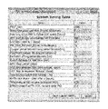
- FIG. 3 shows a system tuning table
- FIG. 4 shows a complete tuning screen.
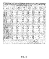
- FIG. 5 shows an RH & SH tuning table.
- FIG. 7 shows a water cannon box.
- FIG. 8 shows and effectiveness table
- the present invention relates to the control of sootblowers in a fossil fueled power plant, in particular to plant applications systems using a graphical programming environment in combination with a set of rules to activate sootblowers.
- the method while not prohibiting the use of models, relies on basic control setpoints and the users knowledge of the unit to set up a relatively simple fuzzy constrained system that can react vary quickly to changing conditions.
- the system can evaluate every few seconds (or less if necessary) whether sootblowing is warranted based on current status of the control setpoints.
- the present invention avoids alarm conditions and maintains temperatures, pressures and spray flows closer to the desired value.
- a time bounded or constrained system permits a system to have flexibility to react to process upsets, whether of short duration, (such as a water canon blowing in the lower part of the furnace), medium duration (such as a mill out of service) or longer duration (such as a fuel switch).
- the minimum time constraint ensures that overblowing does not occur, while the maximum time constraint ensures that blowers are at least periodically activated even if a cleanliness measure indicates that a section is clean. This becomes important because some sections, while clean per the modeling method, may have soot buildup that impacts other sections or should be cleaned periodically to avoid a heat balance change when cleaned. By waiting too long, when these sections are blown, they create large temperature excursions in RH or SH temperature even if the cleanliness measure for that section shows little or no change. Hence, the user need only know what the approximate upper limit should be for the length of time between blows.
- a sootblowing system is broken into its constituent supply headers (a header supplies water, steam or air).
- a system allows only one blower to be active off a header at a given time. If more than one sootblower can be active, then the rule can be modified to permit the maximum allowed for that header. For larger plants, more than one header is normally provided. While the present invention can allow this case to be treated as one large system as most other methods do, the maximum benefit is typically achieved by treating each independently.
- the examples given here are representative of system that has a North and South steam header for sootblowers. Any type of system can be handled by the present invention and is within the scope of the present invention.
- One advantage of this configuration is the ability to shut down one side for maintenance while the other side operates. In a conventional situation, the whole sootblowing system must be bypassed.
- Each sootblower needs to have a minimum and maximum time defined. These can be the middle columns of the individual blower tuning screens. These center columns are shown in FIG. 1 .
- the Minimum Time is the absolute minimum time between activation of a sootblower by system logic. Only by bypassing the present invention or by initiating a manual blow can a user cause a blower to activate more often than the minimum time. This is the preferred embodiment, though their may be circumstances where this limit becomes a guideline like the maximum time.
- the Maximum Time is typically more of a guideline.
- the user can schedule event specific or periodic e-mail's or reports including, but not limited to, the time spent sootblowing, which blowers were activated, the number of blowers past the maximum time line, failed start signals and other events that should be noted or investigated by the end-user.
- the Maximum time adjusted for T and P limits is the actual trigger time for a blower that will queue it for a sootblowing operation. This time and the maximum time will be equal for a clean unit with no physical parameters on approach to limit conditions.
- the Maximum Time, Maximum Time adjusted for dirtiness and Maximum Time adjusted for T and P limits will be >Minimum Time.
- each blower has an individual time window (between the Min. T and Max. T). This window can be expanded or shrunk much like an accordion, but based on physical parameters (global and/or local), which then feeds a ranking and permissive system for determining if any blower should blow, and if yes, which one. There is no limit to the number of factors affecting this time window. Nor is there a limitation to the type function (e.g. linear, non-linear, statistical, n-net, first principles, etc.).
- the sample system has at least two ways to reduce this maximum time.
- One is a global parameter to incorporate unit dirtiness.
- the other is a local parameter based on the grouping of where the sootblowers are located in the furnace and how they affect the desired control parameter.
- the second adjustment is blower specific.
- the system comes with a series of tuning screens such as shown in FIG. 2 with desired limits on physical parameters. As critical values are approached they either expedite a blowing session or they put blowers on hold to prevent a temperature or spray flow limit violation.
- the user may set up any type of equation, but the base system is set up such that a linear relation is set-up between starting at the physical limit+/ ⁇ the approach value. With no time reduction outside this band, and the time reduced to Min. T+0.1% if the physical limit is reached.
- the Maximum Time used is the Maximum Time adjusted for dirtiness. Typically, under no circumstances will the this time fall below Min. Time+0.1%.
- the Maximum Time adjusted for T and P limits is used to determine which blower should blow next. If the Time since last blow exceeds the Maximum Time adjusted for T and P limits, then the blower receives a YES—Need Blow? signal.
- the current rank displays the last pass evaluation of which blower should blow next. This is not a queue, but the current ranking and may change in the next pass.
- the blower ranked number one (1) will blow next as soon as any system constraints on initiating blows are removed (e.g. too soon after last blow started, operator bypass of the system or the like).
- any number of functions may be inserted that adjust the maximum blowing time.
- the functions may be linear or non-linear.
- the functions may shrink or delay the actual activation time limit.
- a blower receives a Yes to activate only when the time since last blow equals or is greater than the Maximum Time adjusted for T and P limits
- the rankings may be determined by any method specified by the user in the logic, but the default set-up will calculate the % of time past the trigger limit. For example, if two blowers are past the max time adj. for T and P trigger, they will be evaluated as follows.
- Trigger Limit Blower B 10 hours, if at 3 hours since last blow, the time based 10%
- Blower A will be ranked higher and be initiated at the next opportunity.
- the user may note that the rankings are dynamic as the system has a build in bias to run the short cycle blowers ahead of long cycle blowers.
- the system tuning screen shown in FIG. 3 is typically the Top Level Screen for control of program operation. It affects the general program operation and the parameters selected are unit specific and typically are the global impact parameters impacting the time windows.
- the user sets up the logic using these tuning parameters ( FIGS. 3 a and 3 b show the GPE implementation for permissive checks and for a diagnostic check).
- a bump time feature for cases where a ‘particularly sooty fuel’ has been burned or the user is testing, dead time, when you are at low power (i.e. the unit cools, causing the metal to contract and slag to fall, delaying any need for sootblowing), detection of a unit outage to reset the time windows, a delay time between any blower activation (acts as a negative permissive to allow the unit control system to settled out between blower activations), criteria for a diagnostic on whether a blower has activated or was aborted early, detection criteria for 3 tries and your out (i.e.
- FEGT Limit Available limit to use in adjusting maximum time to blow.
- UOC event How long at low MW to define UOC event (hours)—This parameter is used to define a Unit of Choice (UOC) event. When a UOC event occurs it will trigger a different set of logic for sootblowing. These include:
- the user will want to see how many long term blowers there are and pick a stagger period, so that blowers are not triggered on start up. For example, if there are 10 long term blowers meeting criteria of Max time of 100 hours. And the stagger is put at 20 hours. The last 6 blowers with times between 100 hours and 200 hours will trigger immediately. A stagger value of 2 hours on the other hand, means none will blow for 80 hours, perhaps too long to wait for the first blow.
- Min_Time_Between Blower Activation (sec)—To avoid starting blowers simultaneously, as soon as a blower activation signal is sent, this triggers a hold on ANY new blower being activated. When this period expires, blowers meeting all other criteria may blow.
- Stagger period between long period blower (hrs)—This parameter will be used when starting the application. It may also be triggered when the Last blow reset to 0 is met and the unit returns to power.
- Long time frame blowers as defined by Definition of long period blower, will be staggered so they do not all start at the same time. The logic will look at each blower's maximum time. If the maximum time is greater than the Definition of long period blower, then starting with the current time it will add Stagger period between long period blowers. This is cumulative, so if the stagger is 4 hours and 10 blowers meet the criteria, the last blower will start with 40 hours of accumulated time.
- Flag to set stagger for long period blower The user may simulate a start of the application or a maintenance outage by setting this to a value of 1. The logic will reset this to 0 after setting the stagger for all the long period blowers.
- long period blowers The parameters described above relating to long period blowers look at the maximum time of all blowers. If they equal or exceed this value they are ‘tagged’ as long period blowers and therefore affected by any logic regarding stagger. Cutoff duration for ‘real’ blow (min)—This is a diagnostic parameter used to detect non-functioning blowers. Also, it avoids treating test blows by maintenance crews as full cleaning events. When a blower is started the start time is noted. When the blower returns to the off state this time is noted and the duration calculated. If the duration is less than the above parameter, the blow is not treated as an official sootblowing operation. This means it will very likely re-queue soon if not immediately, and try again. If after 3 tries, it has not successfully blown, the logic will:
- the ‘real’ blow time period needs to long enough to avoid counting normal maintenance activities as sootblowing operations.
- the system tracks the duration and displays the last duration period in the tuning screens. Picking a value that is 30-60 seconds short of a ‘normal’ blow period is recommended.
- UOC clean period (days)—Defines the period of time since a UOC event or start of the application, when the unit is considered to clean. Only after this time is exceeded will Maximum will begin a linear decent towards the minimum time. This works in concert with the UOC time to maximum ‘dirtiness” (day) and UOC time since last UOC to determine the actual reduction in maximum time.
- UOC time to maximum ‘dirtiness” (not tunable-days)—The actual time since the last UOC event. This is not tunable.
- UOC time to maximum ‘dirtiness” (days) Defines the time at which the unit is considered to at a maximum state of dirtiness due to continued running at full load. When this period is reached the unit will be activated blowers at the highest frequency permitted by the system.
- the Maximum Time adjusted for T and P limits will be equal to the Min T+0.1% Time Blower active (not tunable-%)—This is the percent of time that blowers are active per 24 hour period. This value is written out in the daily e-mail status report. This is not tunable.
- System Blower Alarm clear after x (hours)—When a blower has failed to activate or had too short of a blow period to qualify as a sootblowing operation for 3 tries it is flagged with a system Hold Alarm to prevent activation for the period defined here.
- Effectiveness MW no save data level (MW) The system keeps change in all physical parameters delta values as reflected in the change of the value from the beginning to the end of the sootblowing operation.
- FIG. 4 The most common screen for tuning blower operation is shown in FIG. 4 .
- This screen is an example of a summary screen to display to the user the combination of global and local constraints and the net impact on the time window. It shows the user the result of all the most recent calculations and updates with each program cycle. Many columns are tunable by the user. In this case, the user can adjust the Min. Time to blow and the Max. Time to blow, effectively sets the limits on the time window for the blower activation. As all other parameters are scaled in some fashion to these limits, the next execution pass will automatically update the other parameters and display whether this has a caused a situation for a blower to be in demand to blow.
- Last Active Start Time The time of the last successful blow when the blower was activated.
- Last Activated End Time The time of the last successful blow when the blower switched back to the IDLE state.
- Duration of Last Blow minutes—The difference in time between Last Activated End Time and Last Active Start Time. Should this period be less than the value defined for Cutoff duration for ‘real’ blow (min), then these will be reset to the past know good blow operation.
- Time since last blow (hours)—This is the difference in time form the last completed blow and the current time. If there has been a UOC event, the values will not match as ‘dead time’ will be added for the period of time past the UOC event period definition.
- Minimum Time to Blow Again hours
- the minimum times and maximum times determine the constraints on the system. If the Min. and Max. are too narrow the systems ability to respond to the actual physical conditions becomes constrained. Too wide, and there may occasions of excessive blowing or soot build-up not being shown in the physical parameters. To start it is recommended to start with values that will have the minimum time roughly match your current time sequences, especially if it is believed that the current sequence system is over-blowing. Make a conservative best estimate on how long various sections can go without blowing to set the maximum units. Through unit inspections these values can be tuned over time. In particular, the combination of visual inspections with the effectiveness tables can allow blower specific tuning that results in reduced total blows while achieving better control over operating parameters.
- Rank Wgt. Adj. Fctr System calculated value to bias ranking when certain conditions exist. For example, when the minimum time is not met, the value is multiplied by 0.001 to keep it out the rankings. When the minimum time is met, but it is not yet into trigger range, it is 0.005. Only once the trigger time has been reached will it show a value of 1 or more.
- Rank Wgt Current The current calculated weight. Current Rank (N or S)—The current ranking within the given header. Need Blow?—If all permissive are met and the trigger point is reached (as determined by the Maximum Time adjusted for T and P limits, then this will display a YES.
- Blwer ID Fixed ASCII character identifier for the individual blower.
- Each blower has it's own set of constraints which affect the whether the sootblower should be on hold (let the area get dirtier) or should accelerate the blow period by reducing the maximum time to blow. This get reflected in the trigger value (Maximum Time adjusted for T and P limits).
- Each section of the plant furnace may have slight variations on the limits, but basically they will be of the format shown in FIG. 5 .
- This screen is an example of a screen to display and tune for local constraints impacting the time window for an individual blower in a group. It shows the user the result of all the most recent calculations and updates with each program cycle. Some columns are tunable by the user. Below is an example of one possible configuration for tuning the RH and SH blowers. It involves both adjustments to the Max Time (shrinking the time window towards the minimum) and invoking negative permissives which prohibit blows unless the conditions permit.
- RH/SH B TEMP LO Lmt This is the low limit for the reheat or superheat temperature. The goal is to blow often enough to keep the temperature above his value.
- the trigger value Maximum Time adjusted for T and P limits will start moving towards the minimum time when the actual temperature is at RH/SH B TEMP LO Lmt+LO Limit Approach Zone. If the actual temperature drops to the RH/SH B TEMP LO Lmt, the Maximum Time adjusted for T and P limits will be at Min. T+0.1%. This is tunable per blower. Note, the limits allow side to side tuning.
- RH/SH B TEMP HI Lmt The temperature at which the blower will be put into a system HOLD. This hold will not clear until the temperature has dropped to the RH/SH B TEMP HI Lmt—RH/SH DEAD BAND. So if the limits 1010 and the deadband is 10, the temperature must drop to 1000 before this blower is permitted to activate again. Eng Hold—The engineer can force a hold condition by entering a 1. This will keep the blower in HOLD until the engineer manually turns this value back to 0/RH/SH A TEMP LO Lmt—Same as RH/SH B TEMP LO Lmt, only the opposite side (A side versus B side). RH/SH A TEMP—The actual A reheat temperature.
- RH/SH A TEMP HI Lmt Shorte as RH/SH B TEMP HI Lmt, only the opposite side (A side versus B side).
- RH/SH DEAD BAND The value subtracted from a HI lmt hold condition before the hold condition will clear.
- LO Limit Approach Zone The value added to a low limit at which time the Maximum Time adjusted for T and P limits begin to be reduced linearly towards the Minimum Time.
- FIG. 6 is the Economizer Tuning Screen. This screen is a second example of a screen to display and tune for local constraints impacting the time window for an individual blower in a group. It shows the user the result of all the most recent calculations and updates with each program cycle. Some columns are tunable by the user. This is similar to the RH and SH Temperature tuning screen, but ‘reverse’ acting on the desired temperature with regards to permissive prohibit generation and shrinking the time window on T approach.
- FIG. 7 is an example of interacting with an independent blowing system, in this case an Intelligent Water Canon Cleaning system.
- the present invention has also enabled a Water Cannon delay adjustment based on the RH Spray flow levels.
- a simple delay period time window for water canon activation
- the Water Cannon screen is shown in FIG. 7 . This leaves the ‘intelligent logic’ in the water canon untouched except for the delay between the blower activation.
- the knowledge based sootblwoing system can interact with any number of other systems to implement increasing complex strategies.
- the system of the present invention keeps tables of the effectiveness of every blower versus every analog collected by the KSB data link. These must meet the steady state conditions defined in the System Tuning and they are averaged over the last 20 valid sootblowing operations or any other predetermined number. The table is show below in FIG. 8 .
- Effectiveness tables are built for ‘clean unit’ and ‘dirty unit’ as defined by the parameter UOC clean period (days). Blows that occur during the clean period and are steady state are put into the clean table and blows after the UOC clean period are put into the dirty unit table. There will be many compounding factors, such as fuel type, other blowers running, unit demand MW changing, mills in service, etc. These tables do not try to capture this, but are averaged over a long period to show correlations to help tune the individual blower limits. They are to used for guidance in tuning. It is not recommended any automatic feedback loops be implemented using this data. For example, if N01_RH continues to show a 30 Deg. F.
- Effectiveness table can be used in many different capacities, from advisor capacity (i.e. data collection) to automatic tuning of slopes and curves in for time window adjustments. They may also feed statistical and n-net and first principal models that in turn may provide feedback to this or other systems.
- the present invention typically includes:
- GPE Graphical Programming Environment
- the system includes auto-retry and an internal fail monitor.
- an internal fail monitor With the GPE it is easy to create additional monitoring of the sootblowing system.
- One example is the creation of a monitor that looks at how long a sootblower has run after activation. If the period is too short, the blower may be restarted as the short duration is symptomatic of an aborted sootblow. For sootblowers not activated very often, water build-up can cause the steam pressure to not meet a permissive value in the PLC thereby causing an early retraction of the blower. In a normal sequence system, this blower can then be skipped until the next time it occurs in a sequence.
- the present invention permits retries because the problem can clear itself.
- the system will generate an alarm and potentially a message (to an operator console, and/or e-mail and/or other reporting mechanism) that highlights that the blower is not functioning properly.
- the blower can be put into an alarm condition prohibiting any sootblowing until the alarm is cleared through maintenance and/or the expiration of a timer.
- the present invention will try again as if the alarm had not occurred, and if it fails again, the cycle will repeat (the blower can also be flagged as suspicious or otherwise).
- the present invention relates to a rule-based system for controlling sootblowing at power plants that uses a time-constrained window and includes a control computer coupled to a sootblowing control system that controls a plurality of sootblowing systems, where a plurality of sootblowing rules stored in the control computer.
- the control computer operates the sootblowing control system in real time according to these rules by incorporating the parameters.
- the control computer generally evaluates each blower during each program cycle to cause a chosen blower to activate.
- the control computer evaluates each blower against DCS control system values and/or models to determine which blower is chosen.
- the system is configured where rules may be added, modified or deleted while the system is running with changes taking affect on a next program cycle or a program cycle designated by a user.
- sootblowing sources such as air water or steam are treated as different systems.
- the system generally has a system retry and an internal fail monitor. The system can activate sootblowers from different headers simultaneously.
- the rule-based graphical system has a graphical control system running on a computer presenting a plurality of tuning screens exposing sootblowing parameters with a plurality of sootblowing rules stored in the graphical control system.
- the graphical control system normally operates a sootblowing control system in real time according to the rules by incorporating the parameters in decisions.
Landscapes
- Engineering & Computer Science (AREA)
- Mechanical Engineering (AREA)
- General Engineering & Computer Science (AREA)
- Physics & Mathematics (AREA)
- Thermal Sciences (AREA)
- Chemical & Material Sciences (AREA)
- Combustion & Propulsion (AREA)
- General Physics & Mathematics (AREA)
- Automation & Control Theory (AREA)
- Incineration Of Waste (AREA)
- Testing And Monitoring For Control Systems (AREA)
Abstract
Description
There is no limit to the number of factors affecting this time window. Nor is there a limitation to the type function (e.g. linear, non-linear, statistical, n-net, first principles, etc.).
Maximum Time adjusted for T and P limits=Min T.+((1−% dirty)*(Max. Time−Min. Time))
Where % dirty=(Days since UOC−UOC clean period)/(Day to Max Dirty−UOC clean period)
-
- 1) Effectively cease blowing and accumulate dead-time (do not accumulate time) for time since last blow. When the UOC event is over, the time returns to accumulation mode and sootblowing will return to normal.
- 2) A counter is reset to zero for unit cleanliness. The counter is used to determine whether a unit as a whole is likely to be ‘clean’ or ‘dirty’ When dirty, the maximum times will start to shrink towards the minimum times. This shrinkage is determined by parameters: UOC clean period and UOC time to maximum ‘dirtiness’. The time accumulated is shown in the parameter UOC time since last UOC.
MW Level to stop accumulated blow time—This parameter determines what load level the term
How long at low MW to define UOC event (hours) will start it's timer. The UOC counter will run until the MW level return above this parameter. There is not data averaging, so any spikes in power will cause a reset in this parameter.
Last blow reset to 0 (days)—If the UOC counter get to this parameter, it assumes the unit has been shutdown for maintenance and resets all parameters. The same result can be achieve if you start and stop the KSB application. This includes: - 1. All blow times (except as noted below) will be reset to the time that power first reaches the MW Level to stop accumulated blow time parameter.
- 2. Long time frame blowers as defined by Definition of long period blower, will be staggered so they do not all start at the same time. The logic will look at each blowers maximum time. If the maximum time is greater than the Definition of long period blower, then starting with the current time it will add Stagger period between long period blowers. This is cumulative, so if the stagger is 4 hours and 10 blowers meet the criteria, the last blower will start with 40 hours of accumulated time.
Flag to set stagger for long period blower—The user may simulate a start of the application or a maintenance outage by setting this to a value of 1. The logic will reset this to 0 after setting the stagger for all the long period blowers.
Cutoff duration for ‘real’ blow (min)—This is a diagnostic parameter used to detect non-functioning blowers. Also, it avoids treating test blows by maintenance crews as full cleaning events. When a blower is started the start time is noted. When the blower returns to the off state this time is noted and the duration calculated. If the duration is less than the above parameter, the blow is not treated as an official sootblowing operation. This means it will very likely re-queue soon if not immediately, and try again. If after 3 tries, it has not successfully blown, the logic will:
-
- 1 Send an e-mail to users indicating a blower problem.
- 2 Put the blower in a system Hold for the period defined by Blwr Alarm—clear after x (hours). No blowing is permitted to be activated by the system during this period. It is hoped the user initiate maintenance and manually activate the blower to test the fix and this will logged and noted by the system. If the system period expires, it will try again with the blower. If it fails 3 times again, it will typically repeat the cycle.
UOC time to maximum ‘dirtiness” (not tunable-days)—The actual time since the last UOC event. This is not tunable.
UOC time to maximum ‘dirtiness” (days) Defines the time at which the unit is considered to at a maximum state of dirtiness due to continued running at full load. When this period is reached the unit will be activated blowers at the highest frequency permitted by the system. The Maximum Time adjusted for T and P limits will be equal to the Min T+0.1%
Time Blower active (not tunable-%)—This is the percent of time that blowers are active per 24 hour period. This value is written out in the daily e-mail status report. This is not tunable.
System Blower Alarm—clear after x (hours)—When a blower has failed to activate or had too short of a blow period to qualify as a sootblowing operation for 3 tries it is flagged with a system Hold Alarm to prevent activation for the period defined here.
Effectiveness MW no save data level (MW)—The system keeps change in all physical parameters delta values as reflected in the change of the value from the beginning to the end of the sootblowing operation. This is average over the last 20 sootblowing operation that meets the definition of steady state. The MW value must have changed by less than the value defined here to qualify as steady state. Note, more than one value may need to be met for the value to be saved. (e.g. Fuel flow ROC).
Effectiveness Fuel Flw ROC no save data (%)—The system keeps change in all physical parameters delta values as reflected in the change of the value from the beginning to the end of the sootblowing operation. This is average over the last 20 sootblowing operation that meets the definition of steady state. The Fuel Flow value must have changed by less than the value defined here to qualify as steady state. Note, more than one value may need to be met for the value to be saved. (Such as MW ROC).
Blower Tuning Screen—Time Constraints
Blwer ID—Fixed ASCII character identifier for the individual blower.
Active—Displays the current blower state. The system reads the status from the PLC for the current state which may include ILDE, RUNNING, LOCAL, OOS and ALARM. In addition, the system can add additional conditions of HOLD (from physical limits), HLD ALM from failure for a blower to start and OPP BLWR which is a prohibit against opposite blowers blowing at the same time.
Last Active Start Time—The time of the last successful blow when the blower was activated.
Last Activated End Time—The time of the last successful blow when the blower switched back to the IDLE state.
Duration of Last Blow (minutes)—The difference in time between Last Activated End Time and Last Active Start Time. Should this period be less than the value defined for Cutoff duration for ‘real’ blow (min), then these will be reset to the past know good blow operation.
Time since last blow (hours)—This is the difference in time form the last completed blow and the current time. If there has been a UOC event, the values will not match as ‘dead time’ will be added for the period of time past the UOC event period definition.
Minimum Time to Blow Again (hours)—Critical Parameter. Unless in Manual, this is the minimum time between blower activations.
Maximum Time adjusted for T and P limits—This is the trigger time, when a blower is allowed to become active. When this value is exceeded a number of permissive will checked and its ranking determined. If all the permissive are clear and the blower is
Maximum Time adjusted for T and P limits—This is an intermediate value for the Maximum. It is the Maximum time adjusted for unit dirtiness.
Maximum Time to Blow Again (Hours)—Critical Parameter. Under ‘ideal’ conditions this is the maximum time allowed to between blower activations for this individual blower. There are situations where various holds and operator bypass conditions may allow this the actual time to exceed this max time.
Rank Wgt Current—The current calculated weight.
Current Rank (N or S)—The current ranking within the given header.
Need Blow?—If all permissive are met and the trigger point is reached (as determined by the Maximum Time adjusted for T and P limits, then this will display a YES.
Eng Hold—The engineer can force a hold condition by entering a 1. This will keep the blower in HOLD until the engineer manually turns this value back to 0/RH/SH
A TEMP LO Lmt—Same as RH/SH B TEMP LO Lmt, only the opposite side (A side versus B side).
RH/SH A TEMP—The actual A reheat temperature.
RH/SH A TEMP HI Lmt—Same as RH/SH B TEMP HI Lmt, only the opposite side (A side versus B side).
RH/SH DEAD BAND—The value subtracted from a HI lmt hold condition before the hold condition will clear.
LO Limit Approach Zone—The value added to a low limit at which time the Maximum Time adjusted for T and P limits begin to be reduced linearly towards the Minimum Time.
Claims (7)
Priority Applications (3)
| Application Number | Priority Date | Filing Date | Title |
|---|---|---|---|
| US13/315,994 US8892477B2 (en) | 2011-12-09 | 2011-12-09 | Method and system for fuzzy constrained sootblowing optimization |
| US14/546,261 US9360212B2 (en) | 2011-12-09 | 2014-11-18 | Controlling sootblowers according to rules, rankings of sootblowers, and fuzzy functions that evaluates fuzzy functions only related to temperature and pressure |
| US15/174,078 US9857073B2 (en) | 2011-12-09 | 2016-06-06 | Method and system for fuzzy constrained sootblowing optimization |
Applications Claiming Priority (1)
| Application Number | Priority Date | Filing Date | Title |
|---|---|---|---|
| US13/315,994 US8892477B2 (en) | 2011-12-09 | 2011-12-09 | Method and system for fuzzy constrained sootblowing optimization |
Related Child Applications (1)
| Application Number | Title | Priority Date | Filing Date |
|---|---|---|---|
| US14/546,261 Continuation US9360212B2 (en) | 2011-12-09 | 2014-11-18 | Controlling sootblowers according to rules, rankings of sootblowers, and fuzzy functions that evaluates fuzzy functions only related to temperature and pressure |
Publications (2)
| Publication Number | Publication Date |
|---|---|
| US20130146089A1 US20130146089A1 (en) | 2013-06-13 |
| US8892477B2 true US8892477B2 (en) | 2014-11-18 |
Family
ID=48570864
Family Applications (3)
| Application Number | Title | Priority Date | Filing Date |
|---|---|---|---|
| US13/315,994 Active 2032-11-22 US8892477B2 (en) | 2011-12-09 | 2011-12-09 | Method and system for fuzzy constrained sootblowing optimization |
| US14/546,261 Active US9360212B2 (en) | 2011-12-09 | 2014-11-18 | Controlling sootblowers according to rules, rankings of sootblowers, and fuzzy functions that evaluates fuzzy functions only related to temperature and pressure |
| US15/174,078 Active US9857073B2 (en) | 2011-12-09 | 2016-06-06 | Method and system for fuzzy constrained sootblowing optimization |
Family Applications After (2)
| Application Number | Title | Priority Date | Filing Date |
|---|---|---|---|
| US14/546,261 Active US9360212B2 (en) | 2011-12-09 | 2014-11-18 | Controlling sootblowers according to rules, rankings of sootblowers, and fuzzy functions that evaluates fuzzy functions only related to temperature and pressure |
| US15/174,078 Active US9857073B2 (en) | 2011-12-09 | 2016-06-06 | Method and system for fuzzy constrained sootblowing optimization |
Country Status (1)
| Country | Link |
|---|---|
| US (3) | US8892477B2 (en) |
Families Citing this family (4)
| Publication number | Priority date | Publication date | Assignee | Title |
|---|---|---|---|---|
| US10222769B2 (en) * | 2012-10-12 | 2019-03-05 | Emerson Process Management Power & Water Solutions, Inc. | Method for determining and tuning process characteristic parameters using a simulation system |
| JP7458180B2 (en) | 2019-12-23 | 2024-03-29 | 川崎重工業株式会社 | Shock wave soot blower system and its operating method |
| CN115510904B (en) * | 2022-09-26 | 2023-08-01 | 天津大学 | Boiler heating area ash monitoring method based on time sequence prediction |
| CN116720446B (en) * | 2023-07-16 | 2023-11-21 | 天津大学 | Method for monitoring thickness of slag layer of water-cooled wall of boiler in real time |
Citations (10)
| Publication number | Priority date | Publication date | Assignee | Title |
|---|---|---|---|---|
| US5181482A (en) | 1991-12-13 | 1993-01-26 | Stone & Webster Engineering Corp. | Sootblowing advisor and automation system |
| US6325025B1 (en) | 1999-11-09 | 2001-12-04 | Applied Synergistics, Inc. | Sootblowing optimization system |
| US6736089B1 (en) | 2003-06-05 | 2004-05-18 | Neuco, Inc. | Method and system for sootblowing optimization |
| US6928937B2 (en) | 2002-12-26 | 2005-08-16 | Diamond Power International, Inc. | Sootblowing control based on boiler thermal efficiency optimization |
| US20090090311A1 (en) * | 2007-10-05 | 2009-04-09 | Neuco, Inc. | Sootblowing optimization for improved boiler performance |
| US20100064470A1 (en) * | 2006-11-06 | 2010-03-18 | Soottech Aktiebolag | Method of rebuilding a sootblowing system of a recovery furnace, a sootblower for a recovery furnace, and a sootblowing system including a plurality of sootblowers |
| US7890197B2 (en) | 2007-08-31 | 2011-02-15 | Emerson Process Management Power & Water Solutions, Inc. | Dual model approach for boiler section cleanliness calculation |
| US7890214B2 (en) | 2005-06-06 | 2011-02-15 | Emerson Process Management Power & Water Solutions, Inc. | Method and apparatus for controlling soot blowing using statistical process control |
| US7891323B2 (en) | 2005-07-29 | 2011-02-22 | Clyde Bergemann Gmbh | Selective cleaning of heat exchanging devices in the boiler of a combustion plant |
| US20110087517A1 (en) * | 2009-10-12 | 2011-04-14 | Abbott Patrick D | Targeted Equipment Monitoring System and Method for Optimizing Equipment Reliability |
Family Cites Families (2)
| Publication number | Priority date | Publication date | Assignee | Title |
|---|---|---|---|---|
| US7584024B2 (en) * | 2005-02-08 | 2009-09-01 | Pegasus Technologies, Inc. | Method and apparatus for optimizing operation of a power generating plant using artificial intelligence techniques |
| US7258695B2 (en) | 2005-02-08 | 2007-08-21 | Sonetics International | Hair restoration device and methods of using and manufacturing the same |
-
2011
- 2011-12-09 US US13/315,994 patent/US8892477B2/en active Active
-
2014
- 2014-11-18 US US14/546,261 patent/US9360212B2/en active Active
-
2016
- 2016-06-06 US US15/174,078 patent/US9857073B2/en active Active
Patent Citations (13)
| Publication number | Priority date | Publication date | Assignee | Title |
|---|---|---|---|---|
| US5181482A (en) | 1991-12-13 | 1993-01-26 | Stone & Webster Engineering Corp. | Sootblowing advisor and automation system |
| US6325025B1 (en) | 1999-11-09 | 2001-12-04 | Applied Synergistics, Inc. | Sootblowing optimization system |
| US6425352B2 (en) | 1999-11-09 | 2002-07-30 | Paul E. Perrone | Sootblowing optimization system |
| US6928937B2 (en) | 2002-12-26 | 2005-08-16 | Diamond Power International, Inc. | Sootblowing control based on boiler thermal efficiency optimization |
| US20090062961A1 (en) * | 2003-06-05 | 2009-03-05 | Neuco, Inc. | Method for sootblowing optimization |
| US7458342B2 (en) | 2003-06-05 | 2008-12-02 | Neuco, Inc. | Method and system for sootblowing optimization |
| US6736089B1 (en) | 2003-06-05 | 2004-05-18 | Neuco, Inc. | Method and system for sootblowing optimization |
| US7890214B2 (en) | 2005-06-06 | 2011-02-15 | Emerson Process Management Power & Water Solutions, Inc. | Method and apparatus for controlling soot blowing using statistical process control |
| US7891323B2 (en) | 2005-07-29 | 2011-02-22 | Clyde Bergemann Gmbh | Selective cleaning of heat exchanging devices in the boiler of a combustion plant |
| US20100064470A1 (en) * | 2006-11-06 | 2010-03-18 | Soottech Aktiebolag | Method of rebuilding a sootblowing system of a recovery furnace, a sootblower for a recovery furnace, and a sootblowing system including a plurality of sootblowers |
| US7890197B2 (en) | 2007-08-31 | 2011-02-15 | Emerson Process Management Power & Water Solutions, Inc. | Dual model approach for boiler section cleanliness calculation |
| US20090090311A1 (en) * | 2007-10-05 | 2009-04-09 | Neuco, Inc. | Sootblowing optimization for improved boiler performance |
| US20110087517A1 (en) * | 2009-10-12 | 2011-04-14 | Abbott Patrick D | Targeted Equipment Monitoring System and Method for Optimizing Equipment Reliability |
Also Published As
| Publication number | Publication date |
|---|---|
| US9360212B2 (en) | 2016-06-07 |
| US20130146089A1 (en) | 2013-06-13 |
| US20150167970A1 (en) | 2015-06-18 |
| US9857073B2 (en) | 2018-01-02 |
| US20170023237A1 (en) | 2017-01-26 |
Similar Documents
| Publication | Publication Date | Title |
|---|---|---|
| US9857073B2 (en) | Method and system for fuzzy constrained sootblowing optimization | |
| US8498746B2 (en) | Sootblowing optimization for improved boiler performance | |
| US7584024B2 (en) | Method and apparatus for optimizing operation of a power generating plant using artificial intelligence techniques | |
| CN1877198B (en) | Method and apparatus for controlling soot blowing using statiscical process control | |
| US8924024B2 (en) | Method for sootblowing optimization | |
| US5181482A (en) | Sootblowing advisor and automation system | |
| DE102006006597B4 (en) | Method and system for determining a steam temperature influencing sequence | |
| CN101326415B (en) | Remote diagnosis and estimation of refrigerant system | |
| EP2444869B1 (en) | Method and apparatus for generalized performance evaluation of equipment using achievable performance derived from statistics and real-time data | |
| CA2639197C (en) | Dual model approach for boiler section cleanliness calculation | |
| JP6983684B2 (en) | Control device, boiler, boiler monitoring image acquisition method and boiler monitoring image acquisition program | |
| Peña et al. | Towards soot-blowing optimization in superheaters | |
| WO1996023169A1 (en) | Process and device for the control of soot blowers in a boiler plant | |
| CN115803563A (en) | Boiler tube group attached ash removing system | |
| CN1938547A (en) | Remote monitoring system of combustion exhaust gas treatment plant | |
| CN109541942A (en) | A kind of boiler oil forecast Control Algorithm and system based on machine learning | |
| Sarunac et al. | Sootblowing operation: the last optimization frontier | |
| Bujalski et al. | The algorithm of steam soot blowers operation based on the monitoring of fouling factors of heating surfaces of a coal-fired boiler under operating conditions | |
| Sarunac et al. | Sootblowing Optimization: Field Experience | |
| Nakoneczny et al. | Implementing B&W’s intelligent sootblowing system at MidAmerican Energy Company’s Louisa Energy Center Unit 1 | |
| Sarunac et al. | Sootblowing Optimization for Opacity Control | |
| JP2023086019A (en) | Plant operation optimization device and plant operation optimization method | |
| Zhu et al. | Research and implementation of soot-blowing optimization on 600MW coal-fired boiler | |
| JP2007233758A (en) | Gasification fusion furnace lifetime cost management support system, and gasification fusion furnace lifetime cost management support method | |
| WO2016208316A1 (en) | System and method for analyzing efficiencies of plant apparatuses |
Legal Events
| Date | Code | Title | Description |
|---|---|---|---|
| STCF | Information on status: patent grant |
Free format text: PATENTED CASE |
|
| FEPP | Fee payment procedure |
Free format text: MAINTENANCE FEE REMINDER MAILED (ORIGINAL EVENT CODE: REM.) |
|
| FEPP | Fee payment procedure |
Free format text: SURCHARGE FOR LATE PAYMENT, SMALL ENTITY (ORIGINAL EVENT CODE: M2554); ENTITY STATUS OF PATENT OWNER: SMALL ENTITY |
|
| MAFP | Maintenance fee payment |
Free format text: PAYMENT OF MAINTENANCE FEE, 4TH YR, SMALL ENTITY (ORIGINAL EVENT CODE: M2551); ENTITY STATUS OF PATENT OWNER: SMALL ENTITY Year of fee payment: 4 |
|
| FEPP | Fee payment procedure |
Free format text: MAINTENANCE FEE REMINDER MAILED (ORIGINAL EVENT CODE: REM.); ENTITY STATUS OF PATENT OWNER: SMALL ENTITY |
|
| FEPP | Fee payment procedure |
Free format text: 7.5 YR SURCHARGE - LATE PMT W/IN 6 MO, SMALL ENTITY (ORIGINAL EVENT CODE: M2555); ENTITY STATUS OF PATENT OWNER: SMALL ENTITY |
|
| MAFP | Maintenance fee payment |
Free format text: PAYMENT OF MAINTENANCE FEE, 8TH YR, SMALL ENTITY (ORIGINAL EVENT CODE: M2552); ENTITY STATUS OF PATENT OWNER: SMALL ENTITY Year of fee payment: 8 |