US8886714B2 - Remote access service for cloud-enabled network devices - Google Patents
Remote access service for cloud-enabled network devices Download PDFInfo
- Publication number
- US8886714B2 US8886714B2 US13/205,238 US201113205238A US8886714B2 US 8886714 B2 US8886714 B2 US 8886714B2 US 201113205238 A US201113205238 A US 201113205238A US 8886714 B2 US8886714 B2 US 8886714B2
- Authority
- US
- United States
- Prior art keywords
- cloud
- network device
- enabled network
- client
- relay server
- Prior art date
- Legal status (The legal status is an assumption and is not a legal conclusion. Google has not performed a legal analysis and makes no representation as to the accuracy of the status listed.)
- Active, expires
Links
- 238000000034 method Methods 0.000 claims abstract description 32
- 230000003068 static effect Effects 0.000 claims description 13
- 238000004891 communication Methods 0.000 claims description 7
- 230000004043 responsiveness Effects 0.000 claims description 7
- 230000004044 response Effects 0.000 claims description 6
- 238000013507 mapping Methods 0.000 claims description 3
- 238000007726 management method Methods 0.000 description 13
- 238000013500 data storage Methods 0.000 description 2
- 230000006870 function Effects 0.000 description 2
- 230000008569 process Effects 0.000 description 2
- 230000001360 synchronised effect Effects 0.000 description 2
- 238000013519 translation Methods 0.000 description 2
- 241001522296 Erithacus rubecula Species 0.000 description 1
- 238000013459 approach Methods 0.000 description 1
- 230000008859 change Effects 0.000 description 1
- 238000010586 diagram Methods 0.000 description 1
- 238000005516 engineering process Methods 0.000 description 1
- 238000003780 insertion Methods 0.000 description 1
- 230000037431 insertion Effects 0.000 description 1
- 230000002093 peripheral effect Effects 0.000 description 1
- 230000002085 persistent effect Effects 0.000 description 1
- 238000007639 printing Methods 0.000 description 1
- 238000012545 processing Methods 0.000 description 1
- 230000001902 propagating effect Effects 0.000 description 1
- 238000012546 transfer Methods 0.000 description 1
- 238000011144 upstream manufacturing Methods 0.000 description 1
Images


Classifications
-
- H—ELECTRICITY
- H04—ELECTRIC COMMUNICATION TECHNIQUE
- H04L—TRANSMISSION OF DIGITAL INFORMATION, e.g. TELEGRAPHIC COMMUNICATION
- H04L67/00—Network arrangements or protocols for supporting network services or applications
- H04L67/01—Protocols
-
- H—ELECTRICITY
- H04—ELECTRIC COMMUNICATION TECHNIQUE
- H04L—TRANSMISSION OF DIGITAL INFORMATION, e.g. TELEGRAPHIC COMMUNICATION
- H04L67/00—Network arrangements or protocols for supporting network services or applications
- H04L67/01—Protocols
- H04L67/10—Protocols in which an application is distributed across nodes in the network
-
- G—PHYSICS
- G06—COMPUTING; CALCULATING OR COUNTING
- G06F—ELECTRIC DIGITAL DATA PROCESSING
- G06F9/00—Arrangements for program control, e.g. control units
- G06F9/06—Arrangements for program control, e.g. control units using stored programs, i.e. using an internal store of processing equipment to receive or retain programs
-
- G—PHYSICS
- G06—COMPUTING; CALCULATING OR COUNTING
- G06F—ELECTRIC DIGITAL DATA PROCESSING
- G06F16/00—Information retrieval; Database structures therefor; File system structures therefor
- G06F16/10—File systems; File servers
- G06F16/13—File access structures, e.g. distributed indices
-
- H—ELECTRICITY
- H04—ELECTRIC COMMUNICATION TECHNIQUE
- H04L—TRANSMISSION OF DIGITAL INFORMATION, e.g. TELEGRAPHIC COMMUNICATION
- H04L63/00—Network architectures or network communication protocols for network security
- H04L63/02—Network architectures or network communication protocols for network security for separating internal from external traffic, e.g. firewalls
- H04L63/029—Firewall traversal, e.g. tunnelling or, creating pinholes
-
- H—ELECTRICITY
- H04—ELECTRIC COMMUNICATION TECHNIQUE
- H04L—TRANSMISSION OF DIGITAL INFORMATION, e.g. TELEGRAPHIC COMMUNICATION
- H04L67/00—Network arrangements or protocols for supporting network services or applications
- H04L67/01—Protocols
- H04L67/02—Protocols based on web technology, e.g. hypertext transfer protocol [HTTP]
Definitions
- the invention generally relates to network devices that are integrated with cloud services, and more particularly to techniques for allowing efficient and secure remote access to such devices.
- cloud storage services provide mass storage through a web service interface available through the Internet.
- the storage infrastructure includes a distributed array of geographically distributed data centers connected to a plurality of clients through a wide area network (WAN).
- a data center typically consists of servers and mass storage facilitating cloud storage services to the clients.
- Such services enable applications including, for example, backup and restore of data, data synchronization, file sharing, and so on.
- Cloud storage services are accessible from anywhere in the world through a client implementing a web services interface designed to at least synchronize data with the data centers.
- web services fail to provide standard file sharing protocols (e.g., common internet file system (CIFS) or network file system (NFS)).
- CIFS common internet file system
- NFS network file system
- accessing files stored in the cloud storage from the LAN is typically many times slower than accessing files stored in storage devices on the same LAN.
- a network attached storage (NAS) device for performing NAS operations with cloud storage services is also discussed in the related art.
- a NAS device provides the functionality of data storage, file-based operations (e.g., read, write, delete, modify, etc.), and the management of these functionalities to clients on the network.
- file-based operations e.g., read, write, delete, modify, etc.
- a client can store data in its local storage which is also synchronized with a cloud storage service.
- the client can access and perform file-based operations either on its local storage or the cloud storage service.
- An access to the files in the device is only through a local area network, while access to the cloud storage is through a web portal.
- An example for a NAS device that provides cloud storage services can be found in a Co-Pending patent application Ser. No.
- Network devices are commonly accessed using a Web-based interface enabling control of the devices.
- a local area network (LAN) in which the devices operate is often protected by a firewall or a network address translation (NAT) device, which prevents remote users from connecting to the device.
- NAT network address translation
- the LAN network may be set with Network Address Translation (NAT) to a dynamic public IP address, which makes locating the device difficult.
- NAT Network Address Translation
- VPN Virtual Private Network
- ADSL Asymmetric Digital Subscriber Line
- Certain embodiments disclosed herein include a method for enabling a remote access to a cloud-enabled network device, the method is performed by a cloud relay server that communicates with at least one client over an internet connection.
- the method comprises receiving a request from a client to access at least a user interface of the cloud-enabled network device through an internet connection, wherein the cloud-enabled network device is connected in a local area network; using a host name designated in the request to detect a cloud connector that communicates with the cloud-enabled network device; sending an open relay message to the cloud-enabled network device through the cloud connector over a management link; and establishing a secure tunnel between the cloud relay server and the cloud-enabled network device, thereby enabling a secure connection between the client and the cloud-enabled network device over the internet connection.
- Certain embodiments disclosed herein also include a method for optimizing communication between a client and a cloud-enabled network device communicating over the internet, wherein the cloud-enabled network device is connected in a local area network and communicates with the cloud replay server over a secure tunnel.
- the method comprises receiving a request from the client to access a user interface of the cloud-enabled network device; checking if the request is for a static resource of the user interface; sending the static resource from the cloud relay server to the client over the internet; and relaying the request to the cloud-enabled network device over the secure tunnel if the request cannot be served by the cloud relay server.
- Certain embodiments disclosed herein also include a cloud storage system that comprises a plurality of cloud connecters connected to a cloud-enable network device through a management link, wherein the cloud-enable network device is connected in a local area network; at least one cloud relay server for at least enabling a client to access the cloud-enable network device through an internet connection by: receiving a request from the client to access at least a user interface of the cloud-enabled network device through the internet connection, using a host name designated in the request to detect one of the plurality of cloud connectors that communicates with the cloud-enabled network device; sending an open relay message to the cloud-enabled network device through the cloud connector over the management link; and establishing a secure tunnel between the cloud relay server and the cloud-enabled network device, thereby enabling a secure connection between the client and the cloud-enabled network device over the internet connection.
- FIG. 1 is a storage network system useful in describing the principles of the invention.
- FIGS. 2A and 2B are exemplary screenshots of a user interface of a device.
- FIG. 3 is a flowchart describing a method for enabling a remote access to the device in accordance with an embodiment of the invention.
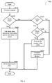
- FIG. 4 is a flowchart describing a method for optimizing communication between a web client and the device in accordance with an embodiment of the invention.
- FIG. 1 shows an exemplary and non-limiting diagram of a storage network system 100 utilized to describe the various embodiments of the invention.
- the system 100 includes a client 110 connected to a device 120 through a local area network (LAN) 130 , which may be either a wireless or wired network.
- LAN local area network
- a client 115 can access the device 120 through a network 150 which may be the Internet or a wide area network (WAN).
- WAN wide area network
- the device 120 is connected to a cloud storage service (CSS) 140 through the network 150 .
- the CSS 140 consists of a plurality of cloud connectors 141 that facilitate connections between the device 120 and storage devices 142 (e.g., disk drives and/or SAN/NAS devices) as well as connections to public cloud storage providers 143 (e.g., Amazon Web Services, Nirvanix, etc.).
- storage devices 142 e.g., disk drives and/or SAN/NAS devices
- public cloud storage providers 143 e.g., Amazon Web Services, Nirvanix, etc.
- the device 120 is a NAS device that provides cloud storage services.
- An example of such a device is disclosed in the co-pending patent application Ser. No. 12/641,559, referenced above.
- the device 120 is connected in the LAN 130 , and as such is protected by a firewall that protects the device from remote access attempts through the Internet.
- the firewall acts also as a NAT device, translating private IP addresses of a device in the LAN to one or more public IP addresses, which are possibly dynamic addresses.
- the CSS 140 also includes at least one cloud relay server 144 , a central directory 145 , and a DNS registration unit 146 all connected to the cloud connectors 141 .
- Each of the cloud connectors 141 is assigned with a fixed internet protocol (IP) address.
- IP internet protocol
- the device 120 establishes a management link 170 with one of the cloud connectors 141 that is selected arbitrarily.
- the management link 170 is an active connection secured using a communication protocol including, but not limited to, Transport Layer Security (TLS), Secure Sockets Layer (SSL), IPSEC, and the like.
- TLS Transport Layer Security
- SSL Secure Sockets Layer
- IPSEC Internet Protocol
- the device 120 sends periodical “keep-alive” messages over the management link to ensure that the connection is alive. If the connection is lost, the management link 170 is re-established by the device 120 . As an outgoing connection, the management link 170 is permitted to pass through any firewall and/or NAT device connected in the LAN 130 . Over the management link 170 , the cloud connector 141 and the device 120 can reliably exchange incoming and outgoing messages.
- the cloud connectors 141 use the central directory 145 to keep records of which device 120 is currently connected to which connector 141 . It should be noted that although a single device 120 is shown in FIG. 1 , the system 100 may include a plurality of devices such as the device 120 connected in the LAN 130 or other LANs. Thus, the cloud connectors 141 can manage the connections to multiple devices 120 .
- the cloud relay server 144 has a secure and trusted communications channel to the cloud connectors 141 and central directory 145 .
- DNS domain name system
- the domain name of the device e.g., devicename.myservice.com
- IP address IP address of the cloud relay server 144 .
- the mapping is performed by insertion of an address record “A” Type record as described, for example, by IETF RFC 1035, DOMAIN NAMES—IMPLEMENTATION AND SPECIFICATION, P. Mockapetris, Section 3.2.2.
- Such mapping is performed by the DNS registration unit 146 under the control of a cloud connector 141 .
- cloud relay server 144 and cloud connector 141 may be implemented as a single server combining both functions.
- the client 115 can remotely access the device 120 using the HTTP protocol, over the network 150 through the cloud relay server 144 .
- a secure tunnel 160 is established from the device 120 to the cloud relay server 144 , under the control of the cloud connector 141 .
- the client 115 can access the device 120 , for example, using an HTTP or HTTPS protocol.
- the device 120 provides to the client an access to a user interface, through which the client 115 (and also client 110 ) can manage and access resources of the device 120 .
- the client 115 can perform file-based operations on files stored in the device 120 , upload/download files, or can configure various setting of the device 120 using the user interface. Exemplary screenshots of the user interface are provided in FIGS. 2A and 2B .
- FIG. 2A depicts an exemplary configuration tab of the device 120 in which a user of client 115 can set the files to be backed up, schedule cloud synchronizations, define user accounts, view reports, set alarms, and so on.
- FIG. 2B is a list of folders including files stored in the device 120 as well as files synchronized with the CSS 140 .
- the user of the client 115 can remotely perform file-based operations on files stored in the device 120 , download files, and upload files to the device.
- FIG. 3 shows an exemplary and non-limiting flowchart 300 describing a method for enabling a remote access to a NAS device that provides cloud services according to an embodiment of the invention.
- the method will be described with a reference to the system 100 depicted in FIG. 1 .
- a request to access the device 120 over the network 150 is received at the cloud relay server 144 .
- the request may be, for example, a hypertext transfer protocol (HTTP) or HTTPS request.
- HTTP hypertext transfer protocol
- a host name (designating the device 120 ) is extracted from the request, e.g., from the Host header of the HTTP request.
- it is checked if there is an existing authenticated tunnel from the cloud relay server 144 to the device 120 , and if so execution ends; otherwise, continuing with S 330 , where the central repository 145 is inquired to retrieve the cloud connector 141 that currently serves the device 120 .
- an open relay message is sent to the device 120 from the cloud relay server 144 to a cloud connector 141 over the management link 170 .
- the open relay message includes the ID of the target device 120 , the IP address of the relay server 144 , a secret token, and the IP address of the client 115 .
- the secret token includes a large random number.
- the device 120 upon reception of the open relay message, opens a connection, the secure tunnel 160 , with the relay server 144 .
- the secure tunnel 160 is an IP connection secured using the protocols SSL, TLS, IPSEC, and the like.
- the device validates the cloud relay server's Security Certificate. If the certificate is valid, the secret token is sent to the relay server 144 over the tunnel 160 .
- the server 144 compares the received secret token with its generated token (included in the open relay message), and if the tokens match the device 120 is considered authenticated and the secure tunnel 160 is set to be active; otherwise, the connection is dropped, at S 360 , and execution ends.
- the secure tunnel becomes inactive when no communication occurs during a predefined time interval.
- clients that seek to remotely access the device 120 and are located in the same network segment as the device 120 can automatically bypass the relay server 144 to communicate with the device directly. This approach will reduce the latency and network traffic to improve responsiveness of the user interface of the device.
- the device 120 reports its internal network interfaces list, defined by pairs of an IP address and a network mask, to a cloud connector 141 over the management link 170 .
- the device 120 also reports its private IP address in the LAN.
- the cloud connector 141 stores the device 120 's public IP address, which is the source IP address of the management link 170 .
- the cloud connector 141 When the cloud connector 141 receives an open relay message (defined above), it is assumed that the client (e.g., client 115 ) can connect to the device 120 directly, without requiring a cloud relay server, if at least one of the following conditions is satisfied: 1) the client's (e.g., client 115 ) source IP address equals to the device public IP address, this is a good indication that the client and the device are behind the same NAT device; and 2) the client's (e.g., client 115 ) source IP address is within the IP network defined by the device 120 reported network interfaces list.
- the client's e.g., client 115
- the cloud relay server 144 returns to the client a permanent redirect response, for example, HTTP 301 Moved Permanently response, replacing the target hostname with the device's private IP address.
- a permanent redirect response for example, HTTP 301 Moved Permanently response, replacing the target hostname with the device's private IP address.
- the client 115 using, for example, its web browser proceeds by communicating directly with the device 120 over the LAN 130 bypassing the cloud relay server 144 entirely.
- FIG. 4 shows an exemplary and non-limiting flowchart 400 illustrating a method for optimizing the communication between a client and cloud-enabled device according to an embodiment of the invention.
- the method will be described with a reference to the system 100 depicted in FIG. 1 .
- the client 115 accesses the device 120 over the Internet through the cloud relay server 144 .
- the client 115 interacts with a user interface of the device 120 in order to change the setting of the device and/or perform file-based operations on files stored in the device.
- the user interface is a web application that can be accessed using a web browser.
- the web application may be embedded in a firmware (or software) that resides in a persistent storage (not shown) of the device 120 .
- the firmware includes, among other things, static files used by the web application, such as HTML and graphics files.
- the screenshot depicted in FIG. 2A contains a collection of icons, which are static files.
- the CSS 140 includes a firmware updates service.
- An updated image of the firmware for each device is maintained by the cloud connectors 141 in a firmware repository 147 .
- the cloud connectors 141 update the device 120 with a new image of the firmware.
- the cloud relay server 144 can access the firmware repository to retrieve an image of the firmware.
- the cloud relay server 144 caches an image of the most updated firmware of each device with which it has an active tunnel 160 .
- the cloud relay server 144 processes the request to determine if it can be satisfied by the cloud relay server 144 .
- a requested uniform resource identifier (URI) in the request is checked against a list of static files. If the URI is found in the static files list, execution continues with S 430 where the static file is retrieved from the cached image of the firmware and returned to the client at S 490 .
- URI uniform resource identifier
- S 420 results with a NO answer, i.e., the requested URI is not found in the static files list, execution proceeds to S 440 , where another check is made to determine if the request is to access a file saved locally in the device 120 . If S 440 results with a YES answer, at S 450 it is checked if the requested file is saved in the CSS 140 . The check is performed by inquiring the cloud connector 141 that maintains the updated status of files managed by the device 120 . If the requested file is in the CSS 144 , then at S 460 , the client 115 is provided with the file stored in the CSS 144 , thus no data is sent or received from the device 120 over the secure tunnel 160 . It should be noted that as the link to the datacenter of CSS 140 is much faster than the Internet connection to the LAN, the latency in accessing the file is significantly reduced.
- the invention has been described with reference to a specific embodiment where the device 120 is a NAS device that enables cloud storage services.
- the teachings disclosed herein can be adapted to support secure, efficient remote access through the Internet to any cloud-enabled device having a user interface, that is, a device having a permanent link to a cloud based service.
- the embodiments of the invention disclosed herein can be implemented as any combination of hardware, firmware, and software.
- the software is preferably implemented as an application program tangibly embodied on a program storage unit or computer readable medium.
- a “computer readable medium” is any non-transitory readable medium, except for a transitory propagating signal, for storing data and can be in a form of a digital circuit, an analogy circuit or combination thereof.
- the application program may be uploaded to, and executed by, a machine comprising any suitable architecture.
- the machine is implemented on a computer platform having hardware such as one or more central processing units (“CPUs”), a memory, and input/output interfaces.
- CPUs central processing units
- the computer platform may also include an operating system and microinstruction code.
- the various processes and functions described herein may be either part of the microinstruction code or part of the application program, or any combination thereof, which may be executed by a CPU, whether or not such computer or processor is explicitly shown.
- various other peripheral units may be connected to the computer platform such as an additional data storage unit and a printing unit.
Abstract
Description
Claims (19)
Priority Applications (3)
| Application Number | Priority Date | Filing Date | Title |
|---|---|---|---|
| US13/205,238 US8886714B2 (en) | 2011-08-08 | 2011-08-08 | Remote access service for cloud-enabled network devices |
| US14/243,926 US9473419B2 (en) | 2008-12-22 | 2014-04-03 | Multi-tenant cloud storage system |
| US14/520,975 US9521217B2 (en) | 2011-08-08 | 2014-10-22 | System and method for remote access to cloud-enabled network devices |
Applications Claiming Priority (1)
| Application Number | Priority Date | Filing Date | Title |
|---|---|---|---|
| US13/205,238 US8886714B2 (en) | 2011-08-08 | 2011-08-08 | Remote access service for cloud-enabled network devices |
Related Child Applications (2)
| Application Number | Title | Priority Date | Filing Date |
|---|---|---|---|
| US12/641,559 Continuation-In-Part US9614924B2 (en) | 2008-12-22 | 2009-12-18 | Storage device and method thereof for integrating network attached storage with cloud storage services |
| US14/520,975 Continuation US9521217B2 (en) | 2011-08-08 | 2014-10-22 | System and method for remote access to cloud-enabled network devices |
Publications (2)
| Publication Number | Publication Date |
|---|---|
| US20130041931A1 US20130041931A1 (en) | 2013-02-14 |
| US8886714B2 true US8886714B2 (en) | 2014-11-11 |
Family
ID=47678211
Family Applications (2)
| Application Number | Title | Priority Date | Filing Date |
|---|---|---|---|
| US13/205,238 Active 2032-01-03 US8886714B2 (en) | 2008-12-22 | 2011-08-08 | Remote access service for cloud-enabled network devices |
| US14/520,975 Active US9521217B2 (en) | 2011-08-08 | 2014-10-22 | System and method for remote access to cloud-enabled network devices |
Family Applications After (1)
| Application Number | Title | Priority Date | Filing Date |
|---|---|---|---|
| US14/520,975 Active US9521217B2 (en) | 2011-08-08 | 2014-10-22 | System and method for remote access to cloud-enabled network devices |
Country Status (1)
| Country | Link |
|---|---|
| US (2) | US8886714B2 (en) |
Cited By (4)
| Publication number | Priority date | Publication date | Assignee | Title |
|---|---|---|---|---|
| US20150089019A1 (en) * | 2013-09-24 | 2015-03-26 | Cyberlink Corp. | Systems and methods for storing compressed data in cloud storage |
| US10205507B2 (en) * | 2015-08-28 | 2019-02-12 | Tejas Networks, Ltd. | Relay architecture, relay node, and relay method thereof |
| US10896200B1 (en) | 2016-06-30 | 2021-01-19 | EMC IP Holding Company LLC | Remote mirroring for data storage systems using cloud backup |
| US11665131B1 (en) | 2022-09-13 | 2023-05-30 | Cisco Technology, Inc. | Stateful redundancy for deterministic carrier-grade network address translation (NAT) services |
Families Citing this family (58)
| Publication number | Priority date | Publication date | Assignee | Title |
|---|---|---|---|---|
| WO2012051298A2 (en) | 2010-10-12 | 2012-04-19 | Nasuni Corporation | Versioned file system with sharing |
| US9015710B2 (en) | 2011-04-12 | 2015-04-21 | Pivotal Software, Inc. | Deployment system for multi-node applications |
| US9170798B2 (en) | 2012-03-02 | 2015-10-27 | Vmware, Inc. | System and method for customizing a deployment plan for a multi-tier application in a cloud infrastructure |
| US20140006482A1 (en) * | 2012-07-02 | 2014-01-02 | Vmware, Inc. | Method and system for providing inter-cloud services |
| US11683292B2 (en) | 2011-09-09 | 2023-06-20 | Kingston Digital, Inc. | Private cloud routing server connection mechanism for use in a private communication architecture |
| US10601810B2 (en) * | 2011-09-09 | 2020-03-24 | Kingston Digital, Inc. | Private cloud routing server connection mechanism for use in a private communication architecture |
| US11863529B2 (en) | 2011-09-09 | 2024-01-02 | Kingston Digital, Inc. | Private cloud routing server connection mechanism for use in a private communication architecture |
| US9516003B2 (en) * | 2011-09-12 | 2016-12-06 | Cache Cloud Llc | Unified cloud computing network interface |
| US10055419B2 (en) * | 2012-02-03 | 2018-08-21 | Apple Inc. | User interface for accessing documents from a computing device |
| US8682957B2 (en) * | 2012-02-16 | 2014-03-25 | Microsoft Corporation | Embedded wireless cloud connector |
| US10031783B2 (en) | 2012-03-02 | 2018-07-24 | Vmware, Inc. | Execution of a distributed deployment plan for a multi-tier application in a cloud infrastructure |
| US9052961B2 (en) | 2012-03-02 | 2015-06-09 | Vmware, Inc. | System to generate a deployment plan for a cloud infrastructure according to logical, multi-tier application blueprint |
| US9047133B2 (en) | 2012-03-02 | 2015-06-02 | Vmware, Inc. | Single, logical, multi-tier application blueprint used for deployment and management of multiple physical applications in a cloud environment |
| US9628438B2 (en) | 2012-04-06 | 2017-04-18 | Exablox | Consistent ring namespaces facilitating data storage and organization in network infrastructures |
| US20130311597A1 (en) * | 2012-05-16 | 2013-11-21 | Apple Inc. | Locally backed cloud-based storage |
| US9348652B2 (en) * | 2012-07-02 | 2016-05-24 | Vmware, Inc. | Multi-tenant-cloud-aggregation and application-support system |
| US20140075319A1 (en) * | 2012-09-11 | 2014-03-13 | Sony Corporation | Establishing cloud server in client device |
| US9817968B2 (en) * | 2012-10-31 | 2017-11-14 | Unisys Corporation | Secure connection for a remote device through a mobile application |
| US9292457B2 (en) | 2012-12-07 | 2016-03-22 | Nimbuz, Inc. | Networking cloud and method of using the same |
| US20140310175A1 (en) * | 2013-04-12 | 2014-10-16 | Jack Bertram Coronel | System and device for exchanging cloud-based digital privileges |
| US9552382B2 (en) | 2013-04-23 | 2017-01-24 | Exablox Corporation | Reference counter integrity checking |
| US9514137B2 (en) | 2013-06-12 | 2016-12-06 | Exablox Corporation | Hybrid garbage collection |
| US9715521B2 (en) | 2013-06-19 | 2017-07-25 | Storagecraft Technology Corporation | Data scrubbing in cluster-based storage systems |
| US9948571B2 (en) * | 2013-06-28 | 2018-04-17 | Oracle International Corporation | System and method for cloud connection pool |
| US9934242B2 (en) | 2013-07-10 | 2018-04-03 | Exablox Corporation | Replication of data between mirrored data sites |
| US20150088942A1 (en) * | 2013-09-25 | 2015-03-26 | Westell Technologies, Inc. | Methods and Systems for Providing File Services |
| US10248556B2 (en) | 2013-10-16 | 2019-04-02 | Exablox Corporation | Forward-only paged data storage management where virtual cursor moves in only one direction from header of a session to data field of the session |
| CN103593406A (en) * | 2013-10-17 | 2014-02-19 | 北京奇虎科技有限公司 | Static resource identifier processing method and device |
| US9985829B2 (en) | 2013-12-12 | 2018-05-29 | Exablox Corporation | Management and provisioning of cloud connected devices |
| JP5939242B2 (en) * | 2013-12-12 | 2016-06-22 | コニカミノルタ株式会社 | Communication system, management server, gateway and program |
| US9405904B1 (en) * | 2013-12-23 | 2016-08-02 | Symantec Corporation | Systems and methods for providing security for synchronized files |
| US9774582B2 (en) * | 2014-02-03 | 2017-09-26 | Exablox Corporation | Private cloud connected device cluster architecture |
| WO2015120071A2 (en) | 2014-02-04 | 2015-08-13 | Exablox Corporation | Content based organization of file systems |
| US9672572B2 (en) * | 2014-03-18 | 2017-06-06 | Sap Se | Real-time availability of omni-channel sales data |
| US20150372863A1 (en) * | 2014-06-18 | 2015-12-24 | Genband Us Llc | Hierarchical resale system for telecommunication products |
| US10616180B2 (en) * | 2014-06-20 | 2020-04-07 | Zscaler, Inc. | Clientless connection setup for cloud-based virtual private access systems and methods |
| US9288272B2 (en) * | 2014-07-10 | 2016-03-15 | Real Innovations International Llc | System and method for secure real-time cloud services |
| WO2016033056A1 (en) * | 2014-08-26 | 2016-03-03 | Ctera Networks, Ltd. | A method and computing device for allowing synchronized access to cloud |
| US20160080492A1 (en) * | 2014-09-15 | 2016-03-17 | 01 Communique Laboratory Inc. | System, computer product, and method for implementing a cloud service with private storage |
| WO2016085541A1 (en) | 2014-11-28 | 2016-06-02 | Nasuni Corporation | Versioned file system with global lock |
| US11627639B2 (en) | 2015-01-26 | 2023-04-11 | Ievgen Verzun | Methods and apparatus for HyperSecure last mile communication |
| US9998434B2 (en) | 2015-01-26 | 2018-06-12 | Listat Ltd. | Secure dynamic communication network and protocol |
| US11277390B2 (en) | 2015-01-26 | 2022-03-15 | Listat Ltd. | Decentralized cybersecure privacy network for cloud communication, computing and global e-commerce |
| US10474654B2 (en) | 2015-08-26 | 2019-11-12 | Storagecraft Technology Corporation | Structural data transfer over a network |
| JP6256442B2 (en) * | 2015-09-29 | 2018-01-10 | コニカミノルタ株式会社 | Image processing system, connection mediation server, relay server, and program |
| US10082955B2 (en) | 2015-12-03 | 2018-09-25 | International Business Machines Corporation | Automated home memory cloud with key authenticator |
| TWI587151B (en) * | 2016-01-06 | 2017-06-11 | Cloud information storage system and method | |
| US10171322B2 (en) * | 2016-01-11 | 2019-01-01 | International Business Machines Corporation | Dynamic and secure cloud to on-premise interaction and connection management |
| US9846553B2 (en) | 2016-05-04 | 2017-12-19 | Exablox Corporation | Organization and management of key-value stores |
| US20210377223A1 (en) * | 2016-05-18 | 2021-12-02 | Zscaler, Inc. | Client to Client and Server to Client communication for private application access through a cloud-based system |
| US10108328B2 (en) | 2016-05-20 | 2018-10-23 | Vmware, Inc. | Method for linking selectable parameters within a graphical user interface |
| US10108447B2 (en) * | 2016-08-30 | 2018-10-23 | Vmware, Inc. | Method for connecting a local virtualization infrastructure with a cloud-based virtualization infrastructure |
| US10157071B2 (en) | 2016-08-30 | 2018-12-18 | Vmware, Inc. | Method for migrating a virtual machine between a local virtualization infrastructure and a cloud-based virtualization infrastructure |
| US10735514B2 (en) * | 2017-08-29 | 2020-08-04 | Western Digital Technologies, Inc. | Remote application configuration on network-attached storage |
| US11057349B2 (en) | 2017-11-03 | 2021-07-06 | Todyl, Inc. | Cloud-based multi-function firewall and zero trust private virtual network |
| US11012431B2 (en) * | 2018-07-31 | 2021-05-18 | International Business Machines Corporation | Secure sharing of peering connection parameters between cloud providers and network providers |
| US10884815B2 (en) | 2018-10-29 | 2021-01-05 | Pivotal Software, Inc. | Independent services platform |
| GB2609677A (en) * | 2021-04-13 | 2023-02-15 | Kingston Digital Inc | Private cloud routing server connection mechanism for use in a private communication architecture |
Citations (5)
| Publication number | Priority date | Publication date | Assignee | Title |
|---|---|---|---|---|
| US20100042720A1 (en) * | 2008-08-12 | 2010-02-18 | Sap Ag | Method and system for intelligently leveraging cloud computing resources |
| US20100161759A1 (en) * | 2008-12-22 | 2010-06-24 | Ctera Networks Ltd. | Storage device and method thereof for integrating network attached storage with cloud storage services |
| US20110054878A1 (en) * | 2009-08-26 | 2011-03-03 | Microsoft Corporation | Automated performance prediction for cloud services |
| US20110082982A1 (en) * | 2009-10-02 | 2011-04-07 | Limelight Networks, Inc. | Content delivery network cache grouping |
| US20120137213A1 (en) * | 2006-09-22 | 2012-05-31 | Oracle International Corporation | User Role Mapping in Web Applications |
Family Cites Families (26)
| Publication number | Priority date | Publication date | Assignee | Title |
|---|---|---|---|---|
| US7962655B2 (en) | 2002-07-29 | 2011-06-14 | Oracle International Corporation | Using an identity-based communication layer for computing device communication |
| US7599496B2 (en) | 2002-08-27 | 2009-10-06 | Pine Valley Investments, Inc. | Secure encryption key distribution |
| US7203796B1 (en) | 2003-10-24 | 2007-04-10 | Network Appliance, Inc. | Method and apparatus for synchronous data mirroring |
| US7546324B2 (en) | 2003-11-13 | 2009-06-09 | Commvault Systems, Inc. | Systems and methods for performing storage operations using network attached storage |
| US7251722B2 (en) | 2004-05-11 | 2007-07-31 | Mistletoe Technologies, Inc. | Semantic processor storage server architecture |
| US20060230245A1 (en) | 2005-04-08 | 2006-10-12 | Microsoft Corporation | Data storage safety indicator and expander |
| US8010498B2 (en) | 2005-04-08 | 2011-08-30 | Microsoft Corporation | Virtually infinite reliable storage across multiple storage devices and storage services |
| US7430639B1 (en) | 2005-08-26 | 2008-09-30 | Network Appliance, Inc. | Optimization of cascaded virtual cache memory |
| US7617391B2 (en) * | 2005-12-15 | 2009-11-10 | Lsi Logic Corporation | Method and apparatus for dynamically selecting one of multiple firmware images for booting an I/O controller |
| US20080005168A1 (en) | 2006-06-30 | 2008-01-03 | Microsoft Corporation | Managing family information |
| US8014308B2 (en) | 2006-09-28 | 2011-09-06 | Microsoft Corporation | Hardware architecture for cloud services |
| US7752180B1 (en) | 2006-12-12 | 2010-07-06 | Network Appliance, Inc. | File system group consistency point |
| US7865663B1 (en) | 2007-02-16 | 2011-01-04 | Vmware, Inc. | SCSI protocol emulation for virtual storage device stored on NAS device |
| US7908490B2 (en) | 2007-06-28 | 2011-03-15 | Novell, Inc. | Techniques for synchronizing and archive-versioning of encrypted files |
| US20090006792A1 (en) | 2007-06-28 | 2009-01-01 | Federwisch Michael L | System and Method to Identify Changed Data Blocks |
| TWI344288B (en) * | 2007-07-23 | 2011-06-21 | Arcadyan Technology Corp | Embedded system with web-based user interface, firmware structure thereof, and method for providing information thereof |
| WO2009032710A2 (en) | 2007-08-29 | 2009-03-12 | Nirvanix, Inc. | Filing system and method for data files stored in a distributed communications network |
| US20090300169A1 (en) | 2008-06-03 | 2009-12-03 | Microsoft Corporation | Synchronization throttling based on user activity |
| US7596620B1 (en) | 2008-11-04 | 2009-09-29 | Aptana, Inc. | System and method for developing, deploying, managing and monitoring a web application in a single environment |
| US8271974B2 (en) | 2008-10-08 | 2012-09-18 | Kaavo Inc. | Cloud computing lifecycle management for N-tier applications |
| US9807468B2 (en) | 2009-06-16 | 2017-10-31 | Microsoft Technology Licensing, Llc | Byte range caching |
| US20100332401A1 (en) | 2009-06-30 | 2010-12-30 | Anand Prahlad | Performing data storage operations with a cloud storage environment, including automatically selecting among multiple cloud storage sites |
| US8078757B2 (en) * | 2009-06-30 | 2011-12-13 | The Go Daddy Group, Inc. | Rewritten URL static and dynamic content delivery |
| US9128626B2 (en) | 2010-10-01 | 2015-09-08 | Peter Chacko | Distributed virtual storage cloud architecture and a method thereof |
| US9311161B2 (en) | 2012-09-14 | 2016-04-12 | Ca, Inc. | Automatically configured management service payloads for cloud IT services delivery |
| US9274843B2 (en) | 2012-09-14 | 2016-03-01 | Ca, Inc. | Multi-redundant switchable process pooling for cloud it services delivery |
-
2011
- 2011-08-08 US US13/205,238 patent/US8886714B2/en active Active
-
2014
- 2014-10-22 US US14/520,975 patent/US9521217B2/en active Active
Patent Citations (5)
| Publication number | Priority date | Publication date | Assignee | Title |
|---|---|---|---|---|
| US20120137213A1 (en) * | 2006-09-22 | 2012-05-31 | Oracle International Corporation | User Role Mapping in Web Applications |
| US20100042720A1 (en) * | 2008-08-12 | 2010-02-18 | Sap Ag | Method and system for intelligently leveraging cloud computing resources |
| US20100161759A1 (en) * | 2008-12-22 | 2010-06-24 | Ctera Networks Ltd. | Storage device and method thereof for integrating network attached storage with cloud storage services |
| US20110054878A1 (en) * | 2009-08-26 | 2011-03-03 | Microsoft Corporation | Automated performance prediction for cloud services |
| US20110082982A1 (en) * | 2009-10-02 | 2011-04-07 | Limelight Networks, Inc. | Content delivery network cache grouping |
Cited By (5)
| Publication number | Priority date | Publication date | Assignee | Title |
|---|---|---|---|---|
| US20150089019A1 (en) * | 2013-09-24 | 2015-03-26 | Cyberlink Corp. | Systems and methods for storing compressed data in cloud storage |
| US9454541B2 (en) * | 2013-09-24 | 2016-09-27 | Cyberlink Corp. | Systems and methods for storing compressed data in cloud storage |
| US10205507B2 (en) * | 2015-08-28 | 2019-02-12 | Tejas Networks, Ltd. | Relay architecture, relay node, and relay method thereof |
| US10896200B1 (en) | 2016-06-30 | 2021-01-19 | EMC IP Holding Company LLC | Remote mirroring for data storage systems using cloud backup |
| US11665131B1 (en) | 2022-09-13 | 2023-05-30 | Cisco Technology, Inc. | Stateful redundancy for deterministic carrier-grade network address translation (NAT) services |
Also Published As
| Publication number | Publication date |
|---|---|
| US9521217B2 (en) | 2016-12-13 |
| US20150046521A1 (en) | 2015-02-12 |
| US20130041931A1 (en) | 2013-02-14 |
Similar Documents
| Publication | Publication Date | Title |
|---|---|---|
| US9521217B2 (en) | System and method for remote access to cloud-enabled network devices | |
| US11949647B2 (en) | Establishing and using a tunnel from an origin server in a distributed edge compute and routing service | |
| US10601782B2 (en) | Systems and methods for proxying encryption key communications between a cloud storage system and a customer security module | |
| US8214451B2 (en) | Network service version management | |
| US8140647B1 (en) | System and method for accelerated data uploading | |
| CN107852604B (en) | System for providing Global Virtual Network (GVN) | |
| US8176189B2 (en) | Peer-to-peer network computing platform | |
| US10313467B2 (en) | Contextual routing device caching | |
| US20070143357A1 (en) | System and method for efficient replication of and access to application specific environments and data | |
| WO2012129468A1 (en) | System and method for sharing data from a local network to a remote device | |
| US20220255993A1 (en) | Replicating data over a public network | |
| WO2010051459A1 (en) | Accessing peer browser caches | |
| US20120191769A1 (en) | Site-aware distributed file system access from outside enterprise network | |
| CN113364741A (en) | Application access method and proxy server | |
| Alimi et al. | A survey of in-network storage systems | |
| US20130054691A1 (en) | Flexible rule based multi-protocol peer-to-peer caching | |
| US20180109563A1 (en) | Hub and Agent Communication Through a Firewall | |
| Roos | Identity management on the blockchain | |
| US8615548B1 (en) | System and method for deferred data downloading | |
| US11218540B1 (en) | System and method for efficient replication of and access to application specific environments and data | |
| Christudas et al. | High Availability and Microservices | |
| Yang | Internet Engineering Task Force (IETF) R. Alimi, Ed. Request for Comments: 6392 Google Category: Informational A. Rahman, Ed. |
Legal Events
| Date | Code | Title | Description |
|---|---|---|---|
| AS | Assignment |
Owner name: CTERA NETWORKS LTD., ISRAEL Free format text: ASSIGNMENT OF ASSIGNORS INTEREST;ASSIGNOR:BRAND, ARON;REEL/FRAME:026716/0292 Effective date: 20110807 |
|
| STCF | Information on status: patent grant |
Free format text: PATENTED CASE |
|
| AS | Assignment |
Owner name: VIOLA CREDIT FIVE (CT), LIMITED PARTNERSHIP, ISRAE Free format text: SECURITY INTEREST;ASSIGNOR:CTERA NETWORKS LTD.;REEL/FRAME:042481/0183 Effective date: 20170518 Owner name: VIOLA CREDIT FIVE (CT), LIMITED PARTNERSHIP, ISRAEL Free format text: SECURITY INTEREST;ASSIGNOR:CTERA NETWORKS LTD.;REEL/FRAME:042481/0183 Effective date: 20170518 |
|
| MAFP | Maintenance fee payment |
Free format text: PAYMENT OF MAINTENANCE FEE, 4TH YR, SMALL ENTITY (ORIGINAL EVENT CODE: M2551) Year of fee payment: 4 |
|
| AS | Assignment |
Owner name: CTERA NETWORKS LTD., ISRAEL Free format text: RELEASE BY SECURED PARTY;ASSIGNOR:VIOLA CREDIT FIVE (CT), LIMITED PARTNERSHIP;REEL/FRAME:047967/0146 Effective date: 20181210 |
|
| AS | Assignment |
Owner name: KREOS CAPITAL VI (EXPERT FUND) LP, JERSEY Free format text: SECURITY INTEREST;ASSIGNOR:CTERA NETWORKS LTD.;REEL/FRAME:052217/0678 Effective date: 20200315 |
|
| AS | Assignment |
Owner name: KREOS CAPITAL VI (EXPERT FUND) L.P., JERSEY Free format text: SECURITY INTEREST;ASSIGNOR:CTERA NETWORKS LTD.;REEL/FRAME:059523/0377 Effective date: 20220330 |
|
| MAFP | Maintenance fee payment |
Free format text: PAYMENT OF MAINTENANCE FEE, 8TH YR, SMALL ENTITY (ORIGINAL EVENT CODE: M2552); ENTITY STATUS OF PATENT OWNER: SMALL ENTITY Year of fee payment: 8 |
|
| AS | Assignment |
Owner name: KREOS CAPITAL VI (EXPERT FUND) L.P., JERSEY Free format text: SECURITY INTEREST;ASSIGNOR:CTERA NETWORKS LTD;REEL/FRAME:065379/0792 Effective date: 20231025 |
|
| AS | Assignment |
Owner name: HAPOALIM BANK B.M., ISRAEL Free format text: SECURITY INTEREST;ASSIGNOR:CTERA NETWORKS LTD.;REEL/FRAME:065671/0256 Effective date: 20231101 |