US8885000B2 - Display panel driving method, display device driving circuit, and display device - Google Patents
Display panel driving method, display device driving circuit, and display device Download PDFInfo
- Publication number
- US8885000B2 US8885000B2 US13/581,042 US201113581042A US8885000B2 US 8885000 B2 US8885000 B2 US 8885000B2 US 201113581042 A US201113581042 A US 201113581042A US 8885000 B2 US8885000 B2 US 8885000B2
- Authority
- US
- United States
- Prior art keywords
- display area
- image data
- display
- correction
- brightness value
- Prior art date
- Legal status (The legal status is an assumption and is not a legal conclusion. Google has not performed a legal analysis and makes no representation as to the accuracy of the status listed.)
- Expired - Fee Related, expires
Links
Images


Classifications
-
- G—PHYSICS
- G09—EDUCATION; CRYPTOGRAPHY; DISPLAY; ADVERTISING; SEALS
- G09G—ARRANGEMENTS OR CIRCUITS FOR CONTROL OF INDICATING DEVICES USING STATIC MEANS TO PRESENT VARIABLE INFORMATION
- G09G3/00—Control arrangements or circuits, of interest only in connection with visual indicators other than cathode-ray tubes
- G09G3/20—Control arrangements or circuits, of interest only in connection with visual indicators other than cathode-ray tubes for presentation of an assembly of a number of characters, e.g. a page, by composing the assembly by combination of individual elements arranged in a matrix no fixed position being assigned to or needed to be assigned to the individual characters or partial characters
- G09G3/2092—Details of a display terminals using a flat panel, the details relating to the control arrangement of the display terminal and to the interfaces thereto
-
- G—PHYSICS
- G09—EDUCATION; CRYPTOGRAPHY; DISPLAY; ADVERTISING; SEALS
- G09G—ARRANGEMENTS OR CIRCUITS FOR CONTROL OF INDICATING DEVICES USING STATIC MEANS TO PRESENT VARIABLE INFORMATION
- G09G2310/00—Command of the display device
- G09G2310/02—Addressing, scanning or driving the display screen or processing steps related thereto
- G09G2310/0232—Special driving of display border areas
-
- G—PHYSICS
- G09—EDUCATION; CRYPTOGRAPHY; DISPLAY; ADVERTISING; SEALS
- G09G—ARRANGEMENTS OR CIRCUITS FOR CONTROL OF INDICATING DEVICES USING STATIC MEANS TO PRESENT VARIABLE INFORMATION
- G09G2320/00—Control of display operating conditions
- G09G2320/02—Improving the quality of display appearance
- G09G2320/0233—Improving the luminance or brightness uniformity across the screen
-
- G—PHYSICS
- G09—EDUCATION; CRYPTOGRAPHY; DISPLAY; ADVERTISING; SEALS
- G09G—ARRANGEMENTS OR CIRCUITS FOR CONTROL OF INDICATING DEVICES USING STATIC MEANS TO PRESENT VARIABLE INFORMATION
- G09G2320/00—Control of display operating conditions
- G09G2320/02—Improving the quality of display appearance
- G09G2320/0271—Adjustment of the gradation levels within the range of the gradation scale, e.g. by redistribution or clipping
-
- G—PHYSICS
- G09—EDUCATION; CRYPTOGRAPHY; DISPLAY; ADVERTISING; SEALS
- G09G—ARRANGEMENTS OR CIRCUITS FOR CONTROL OF INDICATING DEVICES USING STATIC MEANS TO PRESENT VARIABLE INFORMATION
- G09G2320/00—Control of display operating conditions
- G09G2320/06—Adjustment of display parameters
- G09G2320/0686—Adjustment of display parameters with two or more screen areas displaying information with different brightness or colours
-
- G—PHYSICS
- G09—EDUCATION; CRYPTOGRAPHY; DISPLAY; ADVERTISING; SEALS
- G09G—ARRANGEMENTS OR CIRCUITS FOR CONTROL OF INDICATING DEVICES USING STATIC MEANS TO PRESENT VARIABLE INFORMATION
- G09G3/00—Control arrangements or circuits, of interest only in connection with visual indicators other than cathode-ray tubes
- G09G3/20—Control arrangements or circuits, of interest only in connection with visual indicators other than cathode-ray tubes for presentation of an assembly of a number of characters, e.g. a page, by composing the assembly by combination of individual elements arranged in a matrix no fixed position being assigned to or needed to be assigned to the individual characters or partial characters
- G09G3/34—Control arrangements or circuits, of interest only in connection with visual indicators other than cathode-ray tubes for presentation of an assembly of a number of characters, e.g. a page, by composing the assembly by combination of individual elements arranged in a matrix no fixed position being assigned to or needed to be assigned to the individual characters or partial characters by control of light from an independent source
- G09G3/36—Control arrangements or circuits, of interest only in connection with visual indicators other than cathode-ray tubes for presentation of an assembly of a number of characters, e.g. a page, by composing the assembly by combination of individual elements arranged in a matrix no fixed position being assigned to or needed to be assigned to the individual characters or partial characters by control of light from an independent source using liquid crystals
- G09G3/3611—Control of matrices with row and column drivers
- G09G3/3648—Control of matrices with row and column drivers using an active matrix
Definitions
- the present invention relates to a method of driving a display panel, a display device driving circuit, and a display device, in particular to a technology that drives a display panel by supplying an image data to each of display areas of the display panel included in the display device.
- Patent Document 1 discloses a technology for correcting unevenness. According to the technology, a display panel on which an evaluation image is displayed is captured with a camera to obtain a photographic data, and then a brightness distribution and/or a color distribution of the display panel is/are extracted from the photographic data. Then, the extracted brightness distribution and/or the extracted color distribution is/are corrected based on an ideal brightness distribution and/or an ideal color distribution.
- the ideal brightness distribution and/or the ideal color distribution include(s) “non-uniform distribution of display light intensity” that is barely-noticeable to the human eye.
- the brightness distribution and/or the color distribution is/are corrected based on the ideal brightness distribution and/or the ideal color distribution. This reduces deterioration of brightness and gradation characteristics of the entire display area compared with the case that the brightness distribution and/or the color distribution of the display panel is/are corrected to be uniform.
- Patent Document 1 Japanese Unexamined Patent Publication No. 2007-88980
- Patent Document 1 cannot suppress the deterioration of brightness and gradation characteristics that may occur in a middle portion of a display area.
- a display device may have illumination unevenness due to the arrangement of backlights. In such a case, the unevenness may only occur in an outer periphery of the display area and may not occur in the middle portion of the display area, and thus the middle portion of the display area does not require the correction.
- the ideal brightness distribution and/or the ideal color distribution is/are determined for the entire area of the display area. Thus, the middle portion of the display area is always corrected. As a result, the deterioration of brightness and gradation characteristic due to such a correction may occur in the middle portion of the display area.
- the present invention was accomplished in view of the above circumstances. It is an object of the present invention to provide a technology that can advantageously reduce the unevenness and suppress the deterioration of brightness and gradation characteristics at the same time.
- the present invention provides a method of driving a display panel having a display area including a first display area and a second display area.
- the first display area includes a middle portion of the display panel and the second display area includes an outer portion of the display panel around the first display area.
- the method includes supplying image data to each of the first display area and the second display area to display an image therein, and performing a first correction to correct only the image data for the second display area while the image data supplying step is being performed.
- the image data for the second display area is corrected, but the image data for the first display area is not corrected.
- the first display area includes the middle portion of the display panel that is the most easily viewable by a user. Accordingly, the quality of the display panel can be maintained at a high level by reducing the deterioration of brightness and gradation characteristics in the first display area. Further, the first display area is often used for characteristics measurement of the display panel. The characteristics of the display panel can be maintained at a high level by reducing the deterioration of brightness and gradation characteristics in the first display area.
- the method of driving a display panel according to the present invention can advantageously suppress the deterioration of brightness and gradation characteristics in the middle portion and reduce unevenness in an outer portion around the middle portion at the same time.
- the second display area includes at least one outer periphery or opposing two outer peripheries of the display area of the display panel.
- the “outer periphery” of the display area is a part of the display area that separates the display area of the display panel from a non-display area extending outwardly from the display area.
- a display area having a rectangular shape includes four outer peripheries.
- the unevenness in the second display area is more likely to occur in the outer periphery of the display panel.
- An example of this is illumination unevenness caused by the backlight that is used in combination with the display panel.
- the second display area includes one outer periphery or opposing two outer peripheries of the display panel. This reduces the unevenness that may occur in the outer periphery of the display panel.
- the first correction includes correcting the image data for the second display area based on first correction data determined for each of reference gradation levels.
- the gradation levels are selected from displayable gradation levels.
- the correction required for the image data vary according to the gradation level.
- the first image data is determined for each of the reference gradation levels. Accordingly, suitable correction for each gradation level can be performed.
- the first correction data is determined such that the uncorrected brightness value of the image data in the first display area and a corrected brightness value of the image data in the second display area are consecutively present.
- the corrected brightness value is defined by correcting the uncorrected brightness value in the second display area based on the first correction data.
- the image data for the second display area is corrected, but the image data for the first display area is not corrected.
- the boundary may be visible on the display panel as “difference” in the brightness values of the image data.
- the first correction data is determined such that the uncorrected brightness value of the image data in the first display area and the corrected brightness value of the image data in the second display area are consecutive at the boundary.
- the boundary between the first display area and the second display area is less likely to be visible on the display panel.
- the first correction data is determined such that the corrected brightness value of the image data in the second display area becomes smaller toward the outer periphery of the display panel from the middle portion.
- the corrected brightness value is defined by correcting the uncorrected brightness value in the second display area based on the first correction data.
- a second correction may be further performed.
- the second correction corrects the image data for the display area including the first display area and the second display area.
- the second correction is performed after the first correction.
- unevenness such as illumination unevenness may be caused by the backlight in the second display area.
- the unevenness in the second display area is corrected in the first correction, and then the second correction is performed on the area including the first display area and the second display area. This can reduce the correction required for the first display area compared with the case that the area including the first display area and the second display area is corrected in one correction.
- the deterioration of brightness and gradation characteristics of the first display area is less likely to occur.
- the display panel is a liquid crystal panel using liquid crystals. This can reduce the unevenness in the liquid crystal panel used in a large screen television and suppress the deterioration of brightness and gradation characteristics.
- the present invention may be embodied as a driving circuit that performs the above-described method of driving a display panel.
- the driving circuit for a display panel according to the present invention is a driving circuit for the display panel having a display area including the first display area and the second display area.
- the driving circuit includes a supply circuit configured to supply an image data to each of the first display area and the second display area to display the image therein.
- the first display area includes the middle portion of the display panel and the second display area includes an outer portion of the display panel around the first display area.
- the supply circuit includes a first correction circuit configured to correct only the image data for the second display image area. In such a driving circuit, the above-described driving method can be performed, and thus the unevenness in the display panel can be reduced and the deterioration of brightness and gradation characteristics can be suppressed.
- the present invention may be embodied as a display device including a display panel to be driven by the above driving method.
- the display panel has a display area including a first display area and a second display area.
- the first display area includes a middle portion of the display panel and the second display area includes an outer portion of the display panel around the first display area.
- the display device includes a supply circuit configured to supply image data to each of the first display area and the second display area to display the image therein.
- the supply circuit includes a first correction circuit configured to correct the image data for the second display area.
- the above-described driving method can be performed. Accordingly, the unevenness in the display panel can be properly reduced and the deterioration of brightness and gradation characteristics can be suppressed.
- the display device may include the display panel and the backlight unit.
- the backlight unit may include a light source and alight guide plate.
- the light guide plate may have a light entrance surface facing the light source and a light exit surface facing the display panel.
- the light guide plate is configured to guide the light entering the light entrance surface from the light source to the light exit surface.
- the light entrance surface is aside surface of the light guide plate and the light exit surface is a main surface of the light guide plate.
- the second display area is closer to the light source, and thus, the illumination unevenness in the display panel is more likely to occur in the second display area than the first display area.
- the light sources are arranged on a side surface side of the light guide plate. The light enters through the side surface and exits from the main surface of the light guide body.
- the display device includes the first correction circuit that only corrects the image data for the second display area. Thus, even if the unevenness occurs in the second display area, the unevenness can be properly reduced.
- the display device may include the display panel and the backlight unit.
- the backlight unit may include a light source and a diffuser plate.
- the light source faces the display panel.
- the diffuser plate is arranged between the light source and the display panel.
- a direct-type backlight unit in which a light enters from a rear surface of the diffuser plate and exits from a front surface thereof, light sources are regularly arranged on the rear surface of the diffuser plate over the area corresponding to the display area.
- the light cannot reach an area surrounding the regularly arranged light sources, and thus the brightness in the area surrounding the light sources is deteriorated.
- the illumination unevenness is more likely to occur in the second display area that is closer to the area surrounding the light sources than the first display area.
- the display device includes the first correction circuit that only corrects the image data for the second display area. Thus, even if the unevenness occurs in the second display area, the unevenness can be advantageously reduced.
- the unevenness can be reduced and the deterioration of brightness and gradation characteristics can be suppressed.
- FIG. 1 is a view illustrating a configuration of a liquid crystal display device 10 ;
- FIG. 2 is a view illustrating how correction data and a first display area are determined
- FIG. 3 is a flow diagram of a determination processing
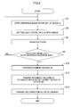
- FIG. 4 is a flow diagram of an arithmetic processing
- FIG. 5 is a diagram illustrating a brightness value distribution before the correction processing in a cross section taken along a line V-V;
- FIG. 6 is a diagram illustrating a brightness value distribution after the correction processing in a cross section taken along a line V-V;
- FIG. 7 is a view illustrating a configuration of a liquid crystal display device 110 ;
- FIG. 8 is an exploded view of a display section 14 including an edge-light type backlight unit 50 ;
- FIG. 9 is an exploded view of a display section 14 including a direct-type backlight unit 150 .
- the first embodiment of the present invention will be described with reference to the drawings.
- the following embodiment will be described using a liquid crystal display device equipped with a liquid crystal panel as a display device.
- the technology according to the present invention is not only applicable to such a display device, but also applicable to an active matrix type display device such as PDP (Plasma Display Panel) display device and an organic EL (electro luminescence) display device, for example.
- the construction of the liquid crystal display device 10 will be explained with reference to FIG. 1 .
- the liquid crystal device 10 includes a supply circuit 12 , a display section 14 , and a backlight drive circuit 16 .
- the display section 14 includes a liquid crystal panel 40 and a backlight unit 50 .
- the liquid crystal panel 40 includes a display area on which an image is displayed.
- the display area of the liquid crystal panel 40 is divided into a first display area 42 and a second display area 44 .
- the first display area 42 includes a middle portion of the display area and the second display area 44 includes an outer portion around the first display area 42 .
- the term “divided” herein is used not only for the display area of the liquid crystal panel 40 that is physically separated, but also the display area that is formally divided into sections by the image data.
- the image data may be supplied to the liquid crystal panel 40 after being divided.
- the second display area 44 extends from a boundary 43 between the first display area 42 and the second display area 44 to an outer periphery 45 of the liquid crystal panel 40 .
- the first display area 42 and the outer peripheries 45 are separated by the second display area 44 .
- the second display area 44 includes all of the outer peripheries 45 .
- the second display area 44 extends along all of the four outer peripheries 45 of the liquid crystal panel 40 that is formed in a rectangular shape.
- the backlight unit 50 is arranged behind the liquid crystal panel 40 .
- FIG. 8 illustrates an exploded view of the display section 14 .
- the backlight unit 50 includes LEDs 54 (Light Emitting Diode) as light sources and a light guide plate 52 .
- the LEDs 54 are arranged to face a side surface of the light guide plate 52 .
- the light guide plate 52 is arranged such that a main surface thereof faces the liquid crystal panel 40 . In the guide plate 52 , the light emitted from the LEDs 54 and entered through the side surface thereof is guided to the main surface that faces the liquid crystal panel 40 .
- the side surface of the light guide plate 52 serves as a light entrance surface 52 A through which the light emitted from the LEDs 54 enters the light guide plate 52 .
- the main surface of the light guide plate 52 serves as a light exit surface 52 B through which the light traveling in the light guide plate 52 exits to illuminate the liquid crystal panel 40 .
- the backlight unit 50 is an edge-light type (side-light type) backlight unit in which the LEDs 54 are arranged at each end portion of the long side of the backlight unit 50 and the light guide plate 52 is arranged therebetween.
- the backlight drive circuit 16 is connected to the LEDs 54 included in the backlight unit 50 .
- the backlight drive circuit 16 supplies current to each of the LEDs 54 .
- the amount of current to be supplied to the LEDs 54 is controlled, and thus the amount of light to be entered into the light guide plate 52 from the LEDs 54 is adjusted.
- the supply circuit 12 supplies image data that is supplied from an external device (not illustrated) to each of the display areas 42 , 44 of the liquid crystal panel 40 .
- the image data includes first image data 42 A for the first display area 42 and second image data 44 A for the second display area 44 .
- the supply circuit 12 supplies the first image data 42 A to the first display area 42 to display a predetermined image in the first display area 42 .
- the supply circuit 12 supplies the second image data 44 A to the second display area 44 to display a predetermined image in the second display area 44 .
- the supply circuit 12 includes a first correction circuit 20 and a second correction circuit 30 .
- the first correction circuit 20 performs a first correction on the second image data 44 A.
- the first correction circuit 20 includes a first processing section 22 , a first memory 26 , and a first SDRAM 27 .
- the first processing section 22 includes a first timing detecting circuit 24 that measures time elapsed from the start of the image data supply.
- the input timing of the first image data 42 A and the second image data 44 A is determined in advance based on an arrangement of display elements provided in the display area of the liquid crystal panel 40 .
- the image data is divided into the first image data 42 A and the second image data 44 A based on the elapsed time measured by the first timing detecting circuit 24 . Then, the first correction is performed only on the second image data 44 A.
- the first memory 26 stores first correction data to be used in the first correction.
- the first correction is performed only on the second image data 44 A. Accordingly, the capacity of the first memory 26 can be reduced to a size corresponding to the second image data 44 A.
- the first timing detecting circuit 24 measures time elapsed from the start of the image data supply. Further, the first processing section 22 extracts the second image data 44 A from the image data supplied by the external device. Furthermore, from the first memory 26 , the first SDRAM 17 retrieves the first correction data that correspond to the second image data 44 A extracted by the first processing section 22 . The second image data 44 A is corrected by transferring the first correction data between the first processing section 22 and the first SDRAM 27 .
- the first memory 26 is a non-volatile memory so as not to lose the first correction data even when the power of the supply circuit 12 is turned off. However, the non-volatile memory generally has a lower data transfer rate than a volatile memory such as SDRAM.
- the first correction circuit 20 employs the first SDRAM 27 . A processing rate of the first correction is improved by transferring the correction data between the first processing section 22 and the first SDRAM 27 .
- the second correction circuit 30 performs the second correction on the first image data 42 A and the second image data 44 A.
- the second correction circuit 30 includes a second processing section 32 , a second memory 36 , and a second SDRAM 37 .
- the second processing section 32 includes a second timing detecting circuit 34 that measures time elapsed from the start of the image data supply.
- the second memory 36 stores second correction data to be used in the second correction.
- the second timing detecting circuit 34 measures time elapsed from the start of the image data supply. Further, the second processing section 32 receives the image data subjected to the first correction from the first correction circuit 20 . Furthermore, from the second memory 36 , the second SDRAM 37 retrieves the second correction data corresponding to the image data received by the second processing section 32 . The first image data 42 A and the second image data 44 A are corrected by transferring the second correction data between the second processing section 32 and the second SDRAM 37 . The processing rate of the second correction is also improved by the use of the second SDRAM 37 .
- a determination processing for determining the correction data and the first display area 42 is performed before use.
- the correction data and the first display area 42 should be determined for every liquid crystal display device 10 in view of factors specific to the liquid crystal panel 40 and the backlight unit 50 of each liquid crystal display device 10 .
- the determination processing is performed in advance to determine the correction data and the first display area 42 for a plurality of liquid crystal devices 10 . This facilitates the determination processing in the liquid crystal display devices 10 .
- the above determination processing is performed after the liquid crystal display device 10 is connected as illustrated in FIG. 2 .
- the liquid crystal display device 10 is connected to a signal source 62 .
- the image data supplied by the signal source 62 is displayed on the display area of the liquid crystal panel 40 .
- a camera 66 is arranged on the front of the liquid crystal panel 40 .
- the liquid crystal panel 40 is captured by the camera 66 .
- the signal source 62 and the camera 66 are connected to a computer 64 to perform a specific operation by instructions from the computer 64 .
- the computer 64 is connected to the supply circuit 12 of the liquid crystal display device 10 .
- the information relating to the correction data and the first display area 42 determined by the determination processing is stored in the first memory 26 and the second memory 36 .
- the determination processing will be explained with reference to FIG. 3 .
- the computer 64 supplies the image data from the signal source 62 to the liquid crystal display device 10 (step S 2 ).
- the image data (hereinafter may be referred to as a reference image data) have a reference gradation level and is in solid pattern.
- reference gradation levels are selected from gradation levels displayable on the liquid crystal panel 40 .
- the reference image data for each reference gradation level is stored in the signal source 62 in advance.
- the correction data and the first display area 42 are not determined, and thus the first correction and the second correction are not performed on the reference image data.
- the computer 64 controls the camera 66 to capture the liquid crystal panel 40 (step S 4 ), and then obtains photographic data from the camera 66 (step S 6 ).
- the computer 64 determines whether the photographic data have been obtained for each reference gradation level (step S 8 ). If the photographic data have not been obtained for each reference gradation level (NO in S 8 ), the step S 2 and the step S 6 are repeated. If the photographic data have been obtained for each reference gradation level (YES in S 8 ), an arithmetic processing is performed (step S 10 ).
- the computer 64 extracts brightness value from the photographic data, and a first display area 42 is determined by the extracted brightness value (step S 102 ). More specifically described, the computer 64 compares the extracted brightness value with a target brightness value K to detect a low brightness area that has a brightness value lower than the target brightness value K.
- the target brightness value K is set for each reference gradation level.
- FIG. 5 illustrates a brightness value distribution before the first correction and the second correction in a cross-section taken along a line V-V.
- An area including the unevenness 46 has a brightness value lower than that of the other areas and lower than the target brightness value K (a broken line).
- the computer 64 detects the area including the unevenness 46 as the low brightness area.
- the computer 64 detects the low brightness area for each reference gradation level. Then, the area satisfying the following two conditions is determined as the first display area 42 :
- the “characteristics determination area” is an area for determining the characteristics of the liquid crystal display device 10 . Generally, the characteristics determination area is set at a middle portion of the display area of the liquid crystal panel 40 . A range of the characteristic determination area is determined according to a measurement range of a measuring device used in a characteristics measurement.
- the computer 64 analyzes the characteristics of the photographic data (step S 104 ) and sets a first target data (step S 106 ).
- the first target data is the same as the reference image data in the first display area 42 and is different from the reference image data in the second display area 44 .
- the brightness value in the middle portion of the display area may be improved by the light applied from the outer periphery of the display area in some cases. In such a case, the brightness value in the second display area 44 may be lowered than the brightness value in the first display area 42 .
- the computer 64 sets the first target value in the second display area 44 with reference to the following characteristics of the liquid crystal panel 40 , for example:
- the computer 64 determines the first correction data (step S 108 ). Specifically, correction data is calculated such that the reference image data in the second display are 44 is corrected to the first target data in the second display area 44 . This correction data is determined as the first correction data. In the present embodiment, even when the edge-light type backlight unit 50 is used, the reference image data is corrected to the first target data by the first correction data. As a result, the illumination unevenness is less likely to be caused by the backlight unit 50 .
- the first target data is set for each of the reference gradation levels selected by the computer 64 , and the first correction data is also determined.
- correction required for the image data is different according to gradation level.
- the first correction data is set for each of the selected reference gradation levels, and thus the correction suitable for each gradation level can be performed.
- correction suitable for the gradation level can be performed by linearly interpolating two reference gradation levels close to the gradation level.
- the computer 64 analyzes the first target data (step S 110 ) and sets the second target data (step S 112 ). Even if the brightness value in the first display area 42 is higher than the target brightness value K and no local reduction in the brightness value can be observed, the brightness value may have long-period unevenness. In the long-period unevenness, the brightness value may rise and fall without falling below the target brightness value, for example.
- the computer 64 analyzes the first target data and sets the second target data if the long-period unevenness is detected.
- the second target data in the first display area 42 and the second target data in the second display area 44 are not necessarily the same.
- the second target data may be separately set for the first display area 42 and the second display area 44 .
- the computer 64 determines the second correction data (step S 114 ). Specifically, correction data is calculated such that the first target data is corrected to the second target data. The correction data is determined as the second correction data. This is the end of the arithmetic processing of the computer 64 .
- the second target data is set for each of the reference gradation levels selected by the computer 64 , and the second correction data is also determined.
- the second correction data is set for each of the selected reference gradation levels, and thus the correction suitable for each gradation level can be performed.
- the computer 64 transmits the information relating to the first display area 42 and the first correction data to the first memory 26 (step S 12 ).
- the first memory 26 stores the transmitted information.
- the computer 64 transmits the second correction data to the second memory 36 (step S 14 ).
- the second memory 36 stores the second correction data. This is the end of the determination processing of the computer 64 .
- the timing detecting circuits 24 , 34 in the supply circuit 12 measures the time elapsed from the start of the image data supply. Then, the first correction circuit 20 performs the first correction on the second image data 44 a included in the supplied image data. Then, the second correction circuit 30 performs the second correction on the image data corrected by the first correction circuit 20 .
- the supply circuit 12 supplies the image data corrected by the first correction circuit 20 and the second correction circuit 30 to the liquid crystal panel 40 , and thus an image is displayed on the liquid crystal panel 40 . As a result, the liquid crystal display device 10 operates.
- the first correction circuit 20 in the supply circuit 12 performs the first correction on the supplied image data.
- the first correction circuit 20 performs the first correction on the second image data 44 A of the supplied image data and does not perform the correction on the first image data 42 A.
- the correction on the second image data 44 A can reduce the unevenness in the second display area 44 .
- An example of the unevenness is the illumination unevenness caused by the backlight unit 50 .
- the deterioration of brightness and gradation characteristics of the first display area 42 can be suppressed by not correcting the first image data 42 A.
- the first display area 42 is often used as the characteristics determination area.
- the characteristics of the liquid crystal panel 40 can be maintained at a high level by suppressing deterioration of brightness and gradation characteristics of the first display area 42 .
- the second correction is performed on the supplied image data by the second correction circuit 30 after the first correction is performed by the first correction circuit.
- the difference in brightness value in the illumination unevenness that may occur in the second display area 44 is so large as to extend across the target brightness value K.
- the unevenness in the second display area 44 should be corrected more than the long-period unevenness that may occur in the first display area 42 .
- FIG. 6 illustrates a brightness value distribution of the liquid crystal panel 40 in a cross-section taken along a line V-V.
- the image data subjected to the first correction has been supplied to the liquid crystal panel 40 .
- This image data is the same as the image data supplied to the liquid crystal panel 40 from the supply circuit 12 without the second correction (the second correction is not required).
- the brightness value distribution that is obtained when the reference image data supplied in FIG. 5 is supplied to the supply circuit 12 is indicated.
- the target brightness value K is indicated in a broken line, and the brightness value distribution of the liquid crystal panel 40 in FIG. 5 is indicated in a one-dotted chain line.
- the characteristics of the first correction data will be explained with reference to FIG. 6 .
- the first correction data is determined such that the brightness value of the reference image data subjected to the first correction is consecutive at the boundary 43 between the first display area 42 and the second display area 44 . Accordingly, even if the display area is physically divided into the first display area 42 and the second display area 44 in the correction of the image data for the liquid crystal panel 40 , the boundary 43 between the first display area 42 and the second display area 44 is not visible to the user of the liquid crystal display device 10 .
- the first correction data is determined such that the brightness value of the reference image data subjected to the first correction become smaller toward the outer periphery of the liquid crystal panel 40 from the middle thereof in the second display area 44 . Accordingly, as illustrated in a one-dotted chain line in FIG. 5 , even when the brightness value of the outer periphery of the display area is smaller than that of the middle portion of the display area in the display panel 40 in which the image before the correction is displayed, the reduction in brightness is less likely to be noticed by the user of the liquid crystal display device 10 .
- FIG. 7 A liquid crystal display device 110 according to the second embodiment of the present invention is illustrated in FIG. 7 .
- the liquid crystal display device 110 includes a backlight unit 150 that has a configuration different from that of the liquid crystal display device 10 of the first embodiment.
- FIG. 9 illustrates the display section of the liquid crystal display device 110 in an exploded view.
- the backlight unit 150 includes the LEDs 54 and a diffuser plate 152 .
- the LEDs 54 are arranged so as to face the rear surface of the diffuser plate 152 .
- the diffuser plate 152 is arranged such that the main surface thereof faces the liquid crystal panel 40 .
- the light emitted from the LEDs 54 enters through the rear surface of the diffuser plate 152 .
- the light is diffused by and penetrated through the diffuser plate 52 .
- the diffused light is applied to the liquid crystal panel 40 from the main surface facing the liquid crystal panel 40 .
- the backlight unit 150 is a direct-type backlight unit in which the LEDs 54 are arranged on the rear surface side and the diffuser plate 152 is arranged on the front side in the thickness direction of the backlight unit 150 .
- the illumination unevenness 156 may occur in an outer peripheral area surrounding the LEDs 54 arranged on the rear side of the diffuser plate 152 . This may cause the unevenness 146 on the liquid crystal panel 40 .
- the first display area 42 and the first correction data can be determined using the backlight unit 150 , and the first correction is performed with the determined first correction data. Accordingly, the illumination unevenness is less likely to be caused by the backlight unit 150 .
- the correction data and the first display area 42 are determined based on the brightness value extracted from the photographic data of the liquid crystal panel 40 .
- the present invention is not limited to this.
- a chromaticity value may be extracted from the photographic data and used to determine the correction data and the first display area 42 .
- both of the brightness value and the chromaticity value may be used.
- the first correction circuit 20 and the second correction circuit 30 are described as separate circuits.
- the first correction circuit 20 and the second correction circuit 30 may be one circuit that performs two corrections, like a timing controller (T-CON).
- the first timing detecting circuit 24 and the second detecting circuit 34 may be one timing detecting circuit. The same may be applied to the first memory 26 and the second memory 36 , and the first SDRAM 27 and the Second SDRAM 37 .
- the first correction and the second correction are independently effective and two of them are not necessarily performed.
- the first correction when the illumination unevenness occurs without the long-period unevenness, only the first correction should be performed.
- the long-period unevenness occurs without the illumination unevenness, only the second correction should be performed.
- the LED is used as a light source.
- Alight source other than the LED may be used.
- 10 display device, 12 : supply circuit, 14 : display section, 16 : backlight drive circuit, 20 : first correction circuit, 30 : second correction circuit, 40 : liquid crystal panel, 42 : first display area, 44 : second display area, 45 : outer periphery, 50 : backlight unit, 52 : light guide plate, 52 A: light entrance surface, 52 B: light exiting surface, 54 : LED, 56 : illumination unevenness, 62 : signal source, 64 : computer, 66 : camera, 152 : diffuser plate
Abstract
Description
- (1) the
first display area 42 is broader than a characteristics determination area; and - (2) the
first display area 42 does not include the low brightness area while the condition (1) is satisfied.
- (1) the extracted brightness value distribution;
- (2) the degree of reduction in brightness in the low brightness area; and
- (3) the range of the
first display area 42.
Claims (14)
Applications Claiming Priority (3)
| Application Number | Priority Date | Filing Date | Title |
|---|---|---|---|
| JP2010064244 | 2010-03-19 | ||
| JP2010-064244 | 2010-03-19 | ||
| PCT/JP2011/052213 WO2011114791A1 (en) | 2010-03-19 | 2011-02-03 | Driving method for display panel, driving circuit for display panel, and display device |
Publications (2)
| Publication Number | Publication Date |
|---|---|
| US20120313983A1 US20120313983A1 (en) | 2012-12-13 |
| US8885000B2 true US8885000B2 (en) | 2014-11-11 |
Family
ID=44648899
Family Applications (1)
| Application Number | Title | Priority Date | Filing Date |
|---|---|---|---|
| US13/581,042 Expired - Fee Related US8885000B2 (en) | 2010-03-19 | 2011-02-03 | Display panel driving method, display device driving circuit, and display device |
Country Status (2)
| Country | Link |
|---|---|
| US (1) | US8885000B2 (en) |
| WO (1) | WO2011114791A1 (en) |
Families Citing this family (3)
| Publication number | Priority date | Publication date | Assignee | Title |
|---|---|---|---|---|
| JP2013044959A (en) * | 2011-08-24 | 2013-03-04 | Canon Inc | Image display device and control method thereof |
| JP6198512B2 (en) * | 2013-08-06 | 2017-09-20 | キヤノン株式会社 | Image display apparatus, control method therefor, and image display system |
| JP2021081494A (en) * | 2019-11-15 | 2021-05-27 | シャープ株式会社 | Image processing system, image processing method, and image processing program |
Citations (6)
| Publication number | Priority date | Publication date | Assignee | Title |
|---|---|---|---|---|
| US20050093798A1 (en) * | 2003-10-29 | 2005-05-05 | Fujitsu Display Technologies Corporation | Correction of uneven image appearance by use of small-size data |
| JP2007088980A (en) | 2005-09-26 | 2007-04-05 | Seiko Epson Corp | Correction data calculation method for luminance irregularity and/or color irregularity |
| JP2008042843A (en) | 2006-08-10 | 2008-02-21 | Funai Electric Co Ltd | Correction of luminance unevenness of screen of liquid crystal panel |
| JP2009237088A (en) | 2008-03-26 | 2009-10-15 | Nanao Corp | Correction method, display device and computer program |
| JP2010015918A (en) | 2008-07-07 | 2010-01-21 | Epson Imaging Devices Corp | Lighting system, electrooptical device and electronic apparatus |
| US20110025730A1 (en) * | 2008-05-30 | 2011-02-03 | Sharp Kabushiki Kaisha | Illumination device, display device, and light guide plate |
-
2011
- 2011-02-03 WO PCT/JP2011/052213 patent/WO2011114791A1/en active Application Filing
- 2011-02-03 US US13/581,042 patent/US8885000B2/en not_active Expired - Fee Related
Patent Citations (7)
| Publication number | Priority date | Publication date | Assignee | Title |
|---|---|---|---|---|
| US20050093798A1 (en) * | 2003-10-29 | 2005-05-05 | Fujitsu Display Technologies Corporation | Correction of uneven image appearance by use of small-size data |
| JP2005134560A (en) | 2003-10-29 | 2005-05-26 | Fujitsu Display Technologies Corp | Display correction circuit and display device |
| JP2007088980A (en) | 2005-09-26 | 2007-04-05 | Seiko Epson Corp | Correction data calculation method for luminance irregularity and/or color irregularity |
| JP2008042843A (en) | 2006-08-10 | 2008-02-21 | Funai Electric Co Ltd | Correction of luminance unevenness of screen of liquid crystal panel |
| JP2009237088A (en) | 2008-03-26 | 2009-10-15 | Nanao Corp | Correction method, display device and computer program |
| US20110025730A1 (en) * | 2008-05-30 | 2011-02-03 | Sharp Kabushiki Kaisha | Illumination device, display device, and light guide plate |
| JP2010015918A (en) | 2008-07-07 | 2010-01-21 | Epson Imaging Devices Corp | Lighting system, electrooptical device and electronic apparatus |
Non-Patent Citations (1)
| Title |
|---|
| An International Search Report, dated Apr. 26, 2011, in International Application No. PCT/JP2011/052213. |
Also Published As
| Publication number | Publication date |
|---|---|
| US20120313983A1 (en) | 2012-12-13 |
| WO2011114791A1 (en) | 2011-09-22 |
Similar Documents
| Publication | Publication Date | Title |
|---|---|---|
| US8937587B2 (en) | Temperature estimating apparatus, method for controlling the same, and image display apparatus | |
| EP2328139B1 (en) | Method of controlling power consumption of a backlight device, a backlight device for an image display device, display device, and a television reception device | |
| EP3340227B1 (en) | Display apparatus and method for driving the same | |
| TWI427586B (en) | A display device, a brightness adjustment device, a backlight device, a brightness adjustment method, and a brightness adjustment program | |
| RU2467366C1 (en) | Liquid crystal display device | |
| US20090262066A1 (en) | Display device | |
| US20100053136A1 (en) | Gradation voltage correction system and display device using the same | |
| US20100020008A1 (en) | Liquid crystal display apparatus | |
| US9189986B2 (en) | Display panel driving method, display device driving circuit, and display device | |
| US9472141B2 (en) | Display apparatus and control method thereof | |
| WO2012147651A1 (en) | Multi-display device and image display device | |
| JP2008268642A (en) | Backlight device, method for controlling backlight and liquid crystal display device | |
| CN110189715B (en) | Method for controlling display of display device, apparatus thereof, and display apparatus | |
| US20140111560A1 (en) | Liquid crystal display device | |
| US20130016138A1 (en) | Display panel driving method, display device driving circuit, and display device | |
| JP2008096696A (en) | Backlight control device, backlight control method and liquid crystal display device | |
| US9618789B2 (en) | Planar lighting apparatus and liquid crystal display apparatus | |
| US10705377B2 (en) | Liquid crystal display device and method of controlling the same | |
| JP2013225110A5 (en) | ||
| US20090058792A1 (en) | Backlight unit, liquid crystal display device including the same, and localized dimming method thereof | |
| KR102119091B1 (en) | Display device and driving method thereof | |
| US8885000B2 (en) | Display panel driving method, display device driving circuit, and display device | |
| US20160155402A1 (en) | Image display apparatus and control method thereof | |
| JP4889520B2 (en) | Video display device | |
| JP6188437B2 (en) | Display device and control method thereof |
Legal Events
| Date | Code | Title | Description |
|---|---|---|---|
| AS | Assignment |
Owner name: SHARP KABUSHIKI KAISHA, JAPAN Free format text: ASSIGNMENT OF ASSIGNORS INTEREST;ASSIGNOR:SASAKI, TAKASHI;REEL/FRAME:028844/0076 Effective date: 20120803 |
|
| STCF | Information on status: patent grant |
Free format text: PATENTED CASE |
|
| FEPP | Fee payment procedure |
Free format text: PAYOR NUMBER ASSIGNED (ORIGINAL EVENT CODE: ASPN); ENTITY STATUS OF PATENT OWNER: LARGE ENTITY |
|
| MAFP | Maintenance fee payment |
Free format text: PAYMENT OF MAINTENANCE FEE, 4TH YEAR, LARGE ENTITY (ORIGINAL EVENT CODE: M1551) Year of fee payment: 4 |
|
| FEPP | Fee payment procedure |
Free format text: MAINTENANCE FEE REMINDER MAILED (ORIGINAL EVENT CODE: REM.); ENTITY STATUS OF PATENT OWNER: LARGE ENTITY |
|
| LAPS | Lapse for failure to pay maintenance fees |
Free format text: PATENT EXPIRED FOR FAILURE TO PAY MAINTENANCE FEES (ORIGINAL EVENT CODE: EXP.); ENTITY STATUS OF PATENT OWNER: LARGE ENTITY |
|
| STCH | Information on status: patent discontinuation |
Free format text: PATENT EXPIRED DUE TO NONPAYMENT OF MAINTENANCE FEES UNDER 37 CFR 1.362 |
|
| FP | Lapsed due to failure to pay maintenance fee |
Effective date: 20221111 |