US8872841B2 - Generating and merging two halftoned images - Google Patents
Generating and merging two halftoned images Download PDFInfo
- Publication number
- US8872841B2 US8872841B2 US11/953,617 US95361707A US8872841B2 US 8872841 B2 US8872841 B2 US 8872841B2 US 95361707 A US95361707 A US 95361707A US 8872841 B2 US8872841 B2 US 8872841B2
- Authority
- US
- United States
- Prior art keywords
- tone
- tone screen
- screen
- bit
- map
- Prior art date
- Legal status (The legal status is an assumption and is not a legal conclusion. Google has not performed a legal analysis and makes no representation as to the accuracy of the status listed.)
- Expired - Fee Related, expires
Links
Images


Classifications
-
- H—ELECTRICITY
- H04—ELECTRIC COMMUNICATION TECHNIQUE
- H04N—PICTORIAL COMMUNICATION, e.g. TELEVISION
- H04N1/00—Scanning, transmission or reproduction of documents or the like, e.g. facsimile transmission; Details thereof
- H04N1/46—Colour picture communication systems
- H04N1/52—Circuits or arrangements for halftone screening
-
- H—ELECTRICITY
- H04—ELECTRIC COMMUNICATION TECHNIQUE
- H04N—PICTORIAL COMMUNICATION, e.g. TELEVISION
- H04N1/00—Scanning, transmission or reproduction of documents or the like, e.g. facsimile transmission; Details thereof
- H04N1/387—Composing, repositioning or otherwise geometrically modifying originals
-
- H—ELECTRICITY
- H04—ELECTRIC COMMUNICATION TECHNIQUE
- H04N—PICTORIAL COMMUNICATION, e.g. TELEVISION
- H04N1/00—Scanning, transmission or reproduction of documents or the like, e.g. facsimile transmission; Details thereof
- H04N1/40—Picture signal circuits
- H04N1/405—Halftoning, i.e. converting the picture signal of a continuous-tone original into a corresponding signal showing only two levels
Definitions
- the subject disclosure is generally directed to a technique for merging a preprint image with a current or primary image.
- print output media employed comprises pre-printed media that includes, for example, a company logo, letterhead, an image, or a pattern.
- pre-printed media is commonly made to order and can be expensive.
- pre-printed media When pre-printed media is used for printing, this essentially overlays two printed images, i.e., the image on the pre-printed media and the image the customer is printing, on paper.
- Pre-printed media is usually expensive. Instead of using pre-printed media, the same effect can be achieved on plain paper. This is done using two steps. First, the user sends a digital document that would generate the contents of pre-printed media, to the printer. This print job is not printed directly, but is rendered and saved as a halftoned bitmap. Later when customers print documents, the saved bitmap will be merged with the current print jobs to simulate the effect of printing using pre-printed media. This way, a user can get the results of pre-printed media on normal paper, resulting in significant savings for the customer.
- Achieving the effect of pre-printed media requires merging two images, the image with the contents of the pre-printed media and the image that the customer tries to print on the pre-print media. While the merging is easier from the algorithm perspective when the two images are continuous tone images, not all printers can handle it this way due to the rendering architecture and memory constraints.
- This invention handles the merging of the two images after they have been halftoned. To achieve acceptable image quality for the merged image, the two images should be halftoned in an interdependent way.
- FIG. 1 is a schematic block diagram of an embodiment of a printing system.
- FIG. 2 is a schematic illustration of an embodiment of a pixel array.
- FIG. 3 is a schematic flow diagram of an embodiment of a procedure for merging a plurality of digital half-tone images.
- FIG. 4 is a schematic flow diagram of an embodiment of a procedure for generating half-tone screens employed in the procedure of FIG. 3 .
- FIG. 5 is a schematic flow diagram of an embodiment of a procedure for generating half-tone screens employed in the procedure of FIG. 3 .
- FIG. 6 is a schematic flow diagram of an embodiment of a procedure for generating half-tone screens employed in the procedure of FIG. 3 .
- FIG. 1 is a schematic block diagram of an embodiment of a printing apparatus that includes an interface 31 that receives print data, for example, from a host computer, and stores the print data in a buffer memory 33 .
- a processor 35 is configured to process the print data to produce bit mapped raster data that is stored in a memory 37 .
- a print engine 39 prints an image pursuant to the bit mapped raster data generated by the processor 35 .
- the print engine 39 can be an electrophotographic print engine or an ink jet print engine, for example.
- Printing is accomplished by selectively printing, depositing, applying or otherwise forming markings such as dots on a receiver surface or substrate that can be a print output medium such as paper or a transfer surface such as a transfer belt or drum. If a transfer surface is used, the image formed or printed on the transfer surface is appropriately transferred to a print output medium such as paper.
- FIG. 2 is a schematic illustration of an embodiment of an array 20 of pixel locations P that can be used to define the locations on a print output medium 41 that can be marked or printed.
- a marking of a particular primary color e.g., cyan magenta, yellow or black
- a dot e.g., cyan magenta, yellow or black
- Each pixel location P can, for example, be marked or printed with (a) one or more non-black color dots (e.g., cyan, magenta or yellow), (b) a black dot by itself, or (c) a black dot and at least one non-black color dot.
- non-black color dots e.g., cyan, magenta or yellow
- Print data typically comprises continuous tone data (such as 32-bit or 24-bit pixel data), and halftoning (e.g., using one or more halftone threshold arrays) is commonly employed to map or transform continuous tone data to a halftoned bit map that contains one bit per pixel per primary color plane, for example.
- continuous tone data such as 32-bit or 24-bit pixel data
- halftoning e.g., using one or more halftone threshold arrays
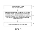
- FIG. 3 is a schematic flow diagram of a procedure for merging a plurality of digital half-tone images.
- a first image is rendered using a first half-tone screen set.
- a second image is rendered using a second half-tone screen set, wherein the first half-tone screen set and the second half-tone screen set have respectively associated screens, and wherein each screen of the second set is less than 100 percent correlated with, and not an inverse of, the associated screen of the first set.
- each half-tone screen set comprises a single half-tone screen that can be utilized for all of the primary colors utilized.
- each half-tone screen set comprises a plurality of half-tone screens, for example, one for each primary color utilized, and each half-tone screen of one set has an associated half-tone screen in the other set, for example for the same color.
- half-tone screens employed herein can comprise stochastic half-tone screens.
- the first and second half-tone images are merged, for example, by using a logical OR operation.
- a half-tone screen of the second set (a second set half-tone screen) can be made from the associated half-tone screen of the first set (a first set half-tone screen) in various ways.
- a second set half-tone screen can be made by copying a first set half-tone screen and shifting the copy by one pixel to produce the second set half-tone screen. More particularly, at 211 the half-tone screens for a first half-tone screen set are defined, and at 213 a copy of the first half-tone screen set is made. At 215 each halftone screen copy is shifted in a predetermined direction by one pixel to produce an associated half-tone screen of the second half-tone screen set.
- a second set half-tone screen can be made by copying a first set half-tone screen and shifting the copy by two pixels to produce the second set half-tone screen. More particularly, at 311 the half-tone screens for a first half-tone screen set are defined, and at 313 a copy of the first half-tone screen set is made. At 315 each halftone screen copy is shifted in a predetermined direction by two pixels to produce an associated half-tone screen of the second half-tone screen set.
- each screen of the second set is defined such that the non-white pixels of dot patterns of such second set half-tone screen for coverage levels between 1 and a predetermined coverage level N are located only at locations that correspond to white pixel locations of a dot pattern of a corresponding first set half-tone screen for a coverage level (MAX-N), wherein MAX is the maximum coverage level (e.g., 255 for 8-bit data) for the first screen and for the second screen.
- MAX is the maximum coverage level (e.g., 255 for 8-bit data) for the first screen and for the second screen.
- the non-white pixels of dot patterns for a second set half-tone screen for coverage levels between 1 and a predetermined coverage level N cannot be located at locations that correspond to non-white pixel locations of a dot pattern of a corresponding first set half-tone screen for a coverage level (MAX-N).
- N can be greater than zero and less than MAX/2, whereby N/MAX is greater than zero and less than 0.5.
- N can be about 0.25*MAX, whereby N/MAX would be about 0.25.
- the non-white pixels of the associated first set half-tone screen and second set half-tone screen tend to be placed at non-overlapping locations.
- a first set half-tone screen dot pattern for a coverage level 192 (out of 255, for example) can be used as a constraining pattern in generating a corresponding second set half-tone second screen.
- this first set half-tone screen dot pattern 3 ⁇ 4 of the pixels are non-white pixels, while 1 ⁇ 4 of the pixels are white pixels.
- the locations corresponding to the white pixels of the first set half-tone screen are candidate locations for the associated second set half-tone screen for coverage levels 1 to 64, i.e., when generating dot patterns for coverage levels 1-64 for the second set half-tone screen, the non-white pixels can only be added to the locations corresponding to the white pixels of the constraining pattern.
Abstract
Description
Claims (10)
Priority Applications (1)
| Application Number | Priority Date | Filing Date | Title |
|---|---|---|---|
| US11/953,617 US8872841B2 (en) | 2007-12-10 | 2007-12-10 | Generating and merging two halftoned images |
Applications Claiming Priority (1)
| Application Number | Priority Date | Filing Date | Title |
|---|---|---|---|
| US11/953,617 US8872841B2 (en) | 2007-12-10 | 2007-12-10 | Generating and merging two halftoned images |
Publications (2)
| Publication Number | Publication Date |
|---|---|
| US20090147019A1 US20090147019A1 (en) | 2009-06-11 |
| US8872841B2 true US8872841B2 (en) | 2014-10-28 |
Family
ID=40721166
Family Applications (1)
| Application Number | Title | Priority Date | Filing Date |
|---|---|---|---|
| US11/953,617 Expired - Fee Related US8872841B2 (en) | 2007-12-10 | 2007-12-10 | Generating and merging two halftoned images |
Country Status (1)
| Country | Link |
|---|---|
| US (1) | US8872841B2 (en) |
Families Citing this family (3)
| Publication number | Priority date | Publication date | Assignee | Title |
|---|---|---|---|---|
| US8896896B2 (en) | 2011-09-13 | 2014-11-25 | Ricoh Production Print Solutions LLC | Preprinted form overlay |
| US8860994B2 (en) | 2012-08-10 | 2014-10-14 | Ricoh Production Print Solutions | Electronic replacement of pre-printed forms |
| US9052851B1 (en) | 2014-02-04 | 2015-06-09 | Ricoh Company, Ltd. | Simulation of preprinted forms |
Citations (7)
| Publication number | Priority date | Publication date | Assignee | Title |
|---|---|---|---|---|
| US5602572A (en) * | 1994-08-25 | 1997-02-11 | Minnesota Mining And Manufacturing Company | Thinned halftone dot patterns for inkjet printing |
| US5734752A (en) * | 1996-09-24 | 1998-03-31 | Xerox Corporation | Digital watermarking using stochastic screen patterns |
| US6252971B1 (en) * | 1998-04-29 | 2001-06-26 | Xerox Corporation | Digital watermarking using phase-shifted stoclustic screens |
| US20040085553A1 (en) * | 2002-10-30 | 2004-05-06 | Eastman Kodak Company | Multitoning a digital image having at least one group of similar colors channels |
| US6804373B1 (en) * | 2000-06-15 | 2004-10-12 | International Business Machines Corporation | Method and system using renormalized pixels for public key and compressed images watermarks on prints |
| US20060120557A1 (en) * | 2004-12-06 | 2006-06-08 | Xerox Corporation | Conjugate cluster screens for embedding digital watermarks into printed halftone documents |
| US7286682B1 (en) * | 2000-08-31 | 2007-10-23 | Xerox Corporation | Show-through watermarking of duplex printed documents |
-
2007
- 2007-12-10 US US11/953,617 patent/US8872841B2/en not_active Expired - Fee Related
Patent Citations (7)
| Publication number | Priority date | Publication date | Assignee | Title |
|---|---|---|---|---|
| US5602572A (en) * | 1994-08-25 | 1997-02-11 | Minnesota Mining And Manufacturing Company | Thinned halftone dot patterns for inkjet printing |
| US5734752A (en) * | 1996-09-24 | 1998-03-31 | Xerox Corporation | Digital watermarking using stochastic screen patterns |
| US6252971B1 (en) * | 1998-04-29 | 2001-06-26 | Xerox Corporation | Digital watermarking using phase-shifted stoclustic screens |
| US6804373B1 (en) * | 2000-06-15 | 2004-10-12 | International Business Machines Corporation | Method and system using renormalized pixels for public key and compressed images watermarks on prints |
| US7286682B1 (en) * | 2000-08-31 | 2007-10-23 | Xerox Corporation | Show-through watermarking of duplex printed documents |
| US20040085553A1 (en) * | 2002-10-30 | 2004-05-06 | Eastman Kodak Company | Multitoning a digital image having at least one group of similar colors channels |
| US20060120557A1 (en) * | 2004-12-06 | 2006-06-08 | Xerox Corporation | Conjugate cluster screens for embedding digital watermarks into printed halftone documents |
Also Published As
| Publication number | Publication date |
|---|---|
| US20090147019A1 (en) | 2009-06-11 |
Similar Documents
| Publication | Publication Date | Title |
|---|---|---|
| JP4724042B2 (en) | Color printing method | |
| US9582226B2 (en) | System and method for producing clear colorant on imposed multi-pass pages | |
| JP4925899B2 (en) | Bitmap-based trapping method and printing system | |
| EP1553753B1 (en) | Color printing | |
| US7508558B2 (en) | Color printing | |
| JP4652258B2 (en) | Printing method | |
| US6545773B1 (en) | Compensation for print-direction induced hue shift using depletion | |
| US8872841B2 (en) | Generating and merging two halftoned images | |
| JP2006270951A (en) | Color printing | |
| JP4078264B2 (en) | Image processing apparatus and method | |
| US8873106B2 (en) | Method and system for enabling halftoning of a color image based on its color separation content | |
| JP2005176035A (en) | Image processing apparatus | |
| JP4598537B2 (en) | Color printing method | |
| US8068257B2 (en) | Color printing reducing artifacts and banding by rendering black dots, replacing dots with process black, and adding non-black dots for different subsets of black dots | |
| CA2445745C (en) | Half-tone based enhancement of black | |
| US20150213344A1 (en) | Image data generating apparatus, an image data generating method, and a printing system | |
| US6742870B2 (en) | Selective enhancement of black | |
| US6799912B2 (en) | Selective enhancement of black |
Legal Events
| Date | Code | Title | Description |
|---|---|---|---|
| AS | Assignment |
Owner name: XEROX CORPORATION, CONNECTICUT Free format text: ASSIGNMENT OF ASSIGNORS INTEREST;ASSIGNOR:YAO, MENG;REEL/FRAME:020223/0350 Effective date: 20071207 |
|
| FEPP | Fee payment procedure |
Free format text: PAYOR NUMBER ASSIGNED (ORIGINAL EVENT CODE: ASPN); ENTITY STATUS OF PATENT OWNER: LARGE ENTITY |
|
| STCF | Information on status: patent grant |
Free format text: PATENTED CASE |
|
| MAFP | Maintenance fee payment |
Free format text: PAYMENT OF MAINTENANCE FEE, 4TH YEAR, LARGE ENTITY (ORIGINAL EVENT CODE: M1551) Year of fee payment: 4 |
|
| FEPP | Fee payment procedure |
Free format text: MAINTENANCE FEE REMINDER MAILED (ORIGINAL EVENT CODE: REM.); ENTITY STATUS OF PATENT OWNER: LARGE ENTITY |
|
| LAPS | Lapse for failure to pay maintenance fees |
Free format text: PATENT EXPIRED FOR FAILURE TO PAY MAINTENANCE FEES (ORIGINAL EVENT CODE: EXP.); ENTITY STATUS OF PATENT OWNER: LARGE ENTITY |
|
| STCH | Information on status: patent discontinuation |
Free format text: PATENT EXPIRED DUE TO NONPAYMENT OF MAINTENANCE FEES UNDER 37 CFR 1.362 |
|
| FP | Lapsed due to failure to pay maintenance fee |
Effective date: 20221028 |