US8872136B1 - Plant eradication using non-mutating low energy rapid unnatural dual component illumination protocol (RUDCIP) in four parameters - Google Patents
Plant eradication using non-mutating low energy rapid unnatural dual component illumination protocol (RUDCIP) in four parameters Download PDFInfo
- Publication number
- US8872136B1 US8872136B1 US13/553,797 US201213553797A US8872136B1 US 8872136 B1 US8872136 B1 US 8872136B1 US 201213553797 A US201213553797 A US 201213553797A US 8872136 B1 US8872136 B1 US 8872136B1
- Authority
- US
- United States
- Prior art keywords
- plant
- exposure
- root
- radiation
- irradiance
- Prior art date
- Legal status (The legal status is an assumption and is not a legal conclusion. Google has not performed a legal analysis and makes no representation as to the accuracy of the status listed.)
- Active, expires
Links
Images


Classifications
-
- A—HUMAN NECESSITIES
- A01—AGRICULTURE; FORESTRY; ANIMAL HUSBANDRY; HUNTING; TRAPPING; FISHING
- A01M—CATCHING, TRAPPING OR SCARING OF ANIMALS; APPARATUS FOR THE DESTRUCTION OF NOXIOUS ANIMALS OR NOXIOUS PLANTS
- A01M21/00—Apparatus for the destruction of unwanted vegetation, e.g. weeds
Definitions
- This invention relates to plant and weed control using illumination trauma and thermal trauma. More specifically, it relates to a relatively low energy rapid unnatural illumination protocol of duration less than one minute to induce plant death, by altering cellular metabolism, causing plant component damage, hormonal changes, damage to photosynthetic apparatus, and possible interruption of healthy symbiosis of a plant root with rhizosphere microorganisms surrounding the root.
- the invention does not use high radiative energy transfers for destruction by severe scalding, heat shock, incineration, or the like.
- ground water is found in natural rock formations called aquifers, and are a vital natural resource with many uses. Over 50% of the USA population relies on ground water as a source of drinking water, especially in rural areas.
- Evaluation of effective methods for plant control using largely non-invasive phenomena is a difficult subject area to evaluate for general effectiveness because of many and varied biologic and environmental factors, including plant species, condition, type, environmental history, solar insolation, weather, and varied actions of insects, animals and microbiotica.
- a typical root comprises various internal layers, including a xylem layer which operates essentially to transport water and provide, when needed, healing substances that repair wounds, such as burn wounds or severing, lacerations, and the like.
- a phloem layer Surrounding the xylem layer is a phloem layer, typically a living transport layer, which transports organic substances such as glucose and other sugars, amino acids and hormones.
- phloem layer Surrounding phloem layer is a cortex, which is in turn surrounded by an epidermis, which acts like a skin which sheds dead cells.
- rhizospheric soil acts as a key root-soil interface of supreme importance for plant health. It is well known that soil-borne microbes interact with plant roots and soil constituents at this root-soil interface. This produces a dynamic environment of root-microbe interactions known as the rhizosphere, whose character and effect on the life of a plant varies widely with differing physical, chemical, and biological properties of the root-associated soil. Root-free soil without such organisms is known as bulk soil.
- Root exudates such as epidermis flakes and other secretions
- rhizodeposition Releasing of root exudates, such as epidermis flakes and other secretions, is sometimes called rhizodeposition and provides growth material, structural material or signals for root-associated microbiota. These microbiota feed on proteins and sugars released by roots. Protozoa and nematodes that feed on bacteria are also present in the rhizosphere, and provide nutrient cycling and disease suppression by warding off pathogens. [Ref: Oxford Journals Journal of Experimental Botany Volume 56, Number 417 Pp. 1761-1778, hereby incorporated in this disclosure in its entirety].
- the balance of populations in a healthy symbiotic rhizosphere is important, because, in part, the bacteria which provide disease suppression interact with pathogens in a variety of ways, including mechanisms of antagonism, such as by competition for nutrients, parasitism, predation and antibiosis. Fungi, too, can be involved, and their actions, when turned from symbiotic to antagonistic, can be lethal for a plant.
- the rhizosphere is soil influenced by roots via release of substances that affect microbial activity.
- the rhizoplane is the root surface, including the strongly adhering soil particles.
- the root itself also participates, because certain micro-organisms, known as endophytes, are able to colonize root tissues.
- Any method to eradicate nuisance vegetation is typically influenced by the overall effect—and possible later influence—on the plant roots, and the rhizosheric soil. Interactions of a plant with electromagnetic radiation have been explored, but easy, safe, clean and efficient eradication meeting certain requirements has been heretofore elusive.
- FIG. 1 a schematic representation of a general electromagnetic spectrum for wavelengths of radiation of significance that are potentially incident upon a plant, with wavelengths ranging from 1 mm to less than 100 nm is shown.
- the near-infrared, or near-IR ranges in wavelength from 700 nm to 3 microns. Visible light is generally taken to range from 700 nm to 400 nm.
- Ultraviolet radiation is generally taken to be of wavelength less than 400 nm, with near-ultraviolet further divided into known portions UV-A (400 ⁇ 320 nm), UV-B (320 ⁇ 280 nm) and UV-C (280 nm ⁇ 100 nm), which is extremely dangerous for humans and is often used as a germicidal radiation to purify water and kill bacteria, viruses, and other organisms.
- FIG. 2 a cartesian plot of both unfiltered solar radiation and net (ground) solar radiation is shown, with spectral radiance in watts per square meter per nanometer versus wavelength in nanometers (nm) is shown.
- Photosynthesis in plants makes use of visible light, especially blue and red visible light, and ultraviolet light, to varying degrees, depending on a host of factors including plant species and type, radiation exposure history and other factors. Approximately seven percent of the electromagnetic radiation emitted from the sun is in a UV range of about 200-400 nm wavelengths.
- UV-C (“shortwave”) radiation 200-280 nm
- UV-B radiation 280-320 nm
- Solar UV-A radiation 320-400 nm
- Plants tend to respond to UV-B irradiation by stimulating protection mechanisms or by activating repair mechanisms to reduce injury and perform repair.
- UV absorbing compounds which include secondary metabolites, mainly phenolic compounds, flavonoids, and hydroxycinnamate esters that accumulate in the vacuoles of epidermal cells in response to UV-B irradiation. These compounds attenuate UV-B range radiation and protect the inner or deeper cell layers, with little absorptive effect on visible light.
- UV-B radiation is considered highly mutagenic, with plant DNA particularly sensitive. UV-B radiation causes phototransformations and can result in production of cyclobutane pyrimidine dimers (CPDs) and pyrimidine (6-4) pyrimidinone dimers (6-4 Pps). DNA and RNA polymerases are generally not able to read through these photoproducts and the elimination of these cytotoxic compounds is essential for DNA replication and transcription and for plant survival. (Britt and May, 2003). To cope, most plants have developed repair mechanisms including photoreactivation, excision, and recombination repair.
- CPDs cyclobutane pyrimidine dimers
- 6-4 pyrimidine
- 6-4 Pps pyrimidinone dimers
- Photoreactivation is a light-dependent enzymatic process using UV-A and blue light to monomerize pyrimidine dimers: Photolyase binds to the photoproducts and then uses light energy to initiate electron transfer to break the chemical bonds of the cyclobutane ring and restore integrity of the bases.
- UV-B light levels such as via the action of the gene RUS1, and can pass this information on to other parts of a plant responsible for growth and development.
- Low dosages of UV-B light can provide important signals to the rest of the plant and can be beneficial to plant growth, helping young plants develop in a timely way, and helping promote seedling morphogenesis.
- too much UV-B light can be toxic to some plants.
- any resulting lethality is not suited for meeting the purposes served by the instant invention, as discussed below.
- allelopathic behavior of plants can be influenced by exposure to added (artificial) UV-B radiation [ref: “Allelopathic Influence of Houndstongue ( Cynoglossum officinale ) and Its Modification by UV-B Radiation,” Nancy H. Furness, Barbara Adomas, Qiujie Dai, Shixin Li, and Mahesh K. Upadhyaya; Weed Technology 2008 22:101-107].
- UV-B radiation can trigger biochemical steps to activate internals processes such as wax production to provide a plant with protection against further ultraviolet radiation [ref: “A UV-B-specific signaling component orchestrates plant UV protection,” Brown B A, Cloix C, Jiang G H, Kaiserli E, Herzyk P, K Kunststoffenstein D J, Jenkins G I; Proc Natl Acad Sci USA. 2005 Dec. 13; 102(50):18225-30. Epub 2005 Dec. 5].
- Plant epidermal flavonoids can protect the photosynthetic apparatus from UVB-mediated damage [ref: “Protection of the D1 photosystem II reaction center protein from degradation in ultraviolet radiation following adaptation of Brassica napus L. to growth in ultraviolet-B,” Wilson, M. I. and B. M.
- FIG. 3 a partial schematic representation of a class of prior art plant eradication using various large infrared radiative transfers is shown.
- a plant Y with root R is shown receiving a large infrared radiative transfer from a forest fire, or any number of prior art infrared radiation-producing processes listed as shown, such as via a flame, an incandescent body, a hot gas, vapor (e.g., steam) or fluid, or via contact with a hot body, or via exposure to known IR or infrared radiators.
- FIG. 3 which shows schematically as an example a FIRE impinging upon plant Y and/or root R
- FIG. 4 showing a burned root with a burned stump as shown, such as might be found after a forest fire, with combustion byproducts, volatilized proteins or smoke 88 rising from the stump as shown. Even obliterating plant Y above ground in this manner typically results in the response shown in FIG. 5 , which shows Regrowth as shown.
- Soil is an excellent thermal insulator both because of the presence of what are essentially refractory materials such as silica, sand, igneous rock particles, and the like—and also because of air content, moisture content, and because of its thermal mass.
- FIGS. 6 and 7 there is depicted one typical class of prior art eradication processes or occurrences whereby extreme ultraviolet light induced trauma is delivered with a large UV radiative transfer via general illumination or flash onto a naturally grown species Digitaria sanguinalis rooted into a soil grade as shown.
- the radiation shown in FIG. 6 is shown for illustrative purposes, ranging from visible light, through UV-A, UV-B and UV-C and beyond, into what is known as Far Ultraviolet, extremely virulent and dangerous forms of radiation.
- UV radiation When plants are normally in sunlight, they tend to develop a waxy layer on their leaves and other similarly exposed components. These plants tend to be resistant to UV radiation.
- monocots and dicots have protective cells, including a well-developed epidermis which comprises a waxy layer on top, called the cuticle. This waxy surface protects the leaves from sunburn, dessication (drying out) and reduces attacks by fungi, bacteria, virus particles and insects. This layer prevents what is called sunscald.
- UV-A levels, UV-B levels, UV-C levels [5] UV-A levels, UV-B levels, UV-C levels
- RERF Radiation Effects Research Foundation
- ABCC Atomic Bomb Casualty Commission
- the first flash or discharge is especially rich in ultraviolet radiation, which is very biologically destructive.
- the total deposition energy of the initial flash alone is such that, with no time for heat dissipation, the temperature of a person's skin would have been raised 50 C by the flash of visible and ultraviolet rays in the first millisecond at a distance of just under 4000 meters from the blast zone.
- the method includes a substantially non-invasive low-energy low irradiance non-mutating method for eradicating a plant in a time under one minute, using a Rapid Unnatural Dual Component Illumination Protocol (RUDCIP) with illumination about the plant, with the method comprising:
- An above-ground foliage and root crown damage illumination component comprising exposure to near-IR radiation directed to any of a foliage of the plant and a root crown of the plant, the near-IR radiation of irradiance E near-IR in W/m 2 and a total exposure time T near-IR in seconds following a RUDCIP Band (RUDCIP BAND) specification;
- a ground-penetrating UV-A illumination component comprising exposure to UV-A radiation directed to any of a root crown of the plant and a soil grade immediately adjacent the root crown; the UV-A radiation of irradiance E UV-A in W/m 2 and a total exposure time T UV-A in seconds following the RUDCIP Band specification; the above-ground foliage and root crown damage illumination component and the ground-penetrating UV-A illumination component each having the exposure times T near-IR and T UV-A of under one minute of total operation, respectively; the RUDCIP Band specification comprising a Red River Crabgrass ( Digitaria cilaris ) protocol specification given
- the method also can include shrouding the plant with a reflective shroud (Sh) to provide at least one foliage avoidance ray derived from the UV-A radiation, or using the shroud to perform any of a stab and a disturb of the soil grade, or using the shroud to shroud at least one plant leaf to avoid absorption block.
- a reflective shroud Sh
- the above-ground foliage and root crown damage illumination component and the ground-penetrating UV-A illumination component can occur at least partially simultaneously, and total exposure times T near-IR and T UV-A can be of duration under 20 seconds, or under 5 seconds, or under 1 second.
- UV-A radiation directed to any of a root crown of the plant and a soil grade immediately adjacent the root crown can be delivered via a UV-A transmissive knife blade (V).
- Machine recognition can be used to locate the plant to be eradicated, and the method can be used to eradicate the plant so located.
- the main method can include a substantially non-invasive low-energy low irradiance non-mutating method for eradicating a plant in a time under one minute, using a high velocity shift in illumination exposure levels to introduce an adaptive stress, the method comprising:
- FIG. 1 shows a schematic representation of a general electromagnetic spectrum for wavelengths potentially incident upon a plant, with wavelengths ranging from 1 mm to less than 100 nm;
- FIG. 2 shows a typical natural filtered and unfiltered solar radiation spectrum using a cartesian plot of spectral radiance versus wavelength
- FIG. 3 shows a partial schematic representation of a class of prior art plant eradication using various large infrared radiative transfers
- FIGS. 4 and 5 show partial cross sectional, partial surface views of a plant in soil, with a root structure in soil, with regrowth after a typical large infrared radiative transfer as depicted in FIG. 3 ;
- FIGS. 6 and 7 show together one typical class of prior art eradication processes or occurrences whereby extreme ultraviolet light induced trauma is delivered with a large UV radiative transfer via general illumination or flash onto a naturally grown species Digitaria sanguinalis rooted into a soil grade;
- FIG. 8 shows a cartesian plot representation of UV frequency regimes and total deposited energy regimes for the high radiative transfer depicted in FIGS. 6 and 7 , with contrast to a typical regime of operation for the instant invention
- FIG. 9 shows a listing of operative attributes for a class of prior art large UV radiative transfers as depicted in FIGS. 6 , 7 , and 8 ;
- FIG. 10 shows a schematic representation of a typical eradication process according to the instant invention, with a dual component illumination protocol shown schematically for two portions of the electromagnetic spectrum as shown in FIG. 1 being directed upon parts of a plant ( Digitaria cilaris ) resting upon a soil grade;
- FIG. 11 shows a close-up view of the bottom portion of FIG. 10 , showing incident near-IR and UV-A rays impinging upon the plant in specific ways, and showing plant foliage, the plant root crown and a soil grade immediately adjacent the root crown;
- FIG. 12 shows a schematic cartesian plot representation of a RUDCIP (Rapid Unnatural Dual Component Illumination Protocol) Band of the instant invention, showing UV-A irradiance and near-IR irradiance levels which constitute the Band, and including a Red River Crabgrass ( Digitaria cilaris ) protocol specification inside the Band;
- RUDCIP Rapid Unnatural Dual Component Illumination Protocol
- FIGS. 13-16 show various schematic cross-sectional shrouded lamp and reflector configurations that may be used to practice some embodiments of the instant invention, with irradiation adjacent a soil grade onto the plant as depicted in FIGS. 10 and 11 ;
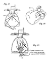
- FIG. 17 shows a schematic cross sectional view of an elliptical reflector shroud configuration that can generate ray patterns helpful for practicing the instant invention
- FIG. 18 shows the elliptical reflector shroud configuration of FIG. 17 in oblique combination cross sectional and surface view
- FIG. 19 shows the schematic cross sectional view of the elliptical reflector shroud configuration of FIG. 17 , with rays being directed upon a plant, and showing a foliage avoidance ray impinging upon a soil grade immediately adjacent a root crown of the plant;
- FIG. 20 shows an oblique view of a partially schematic stab unit of an invasive hot stab plant eradicator as disclosed in U.S. Pat. Nos. 7,954,276 and 8,141,292, modified to provide emission of UV-A radiation;
- FIGS. 21 and 22 show using part surface, part schematic views the stab unit of FIG. 20 , inducing a hot or cold stab gash wound upon a plant root, with direct emission of UV-A radiation into a root of the plant, below soil grade;
- FIG. 23 shows a schematic series of apparatus and process components for using the teachings of the instant invention with machine recognition and automated processes
- FIG. 24 shows a schematic representation of a mobile unit of the machine recognition embodiment depicted in FIG. 23 , showing communication to an imager;
- FIG. 25 shows a listing of possible adaptive stress vectors upon a plant which can arise while practicing the instant invention.
- Exposure Sohall be that due to radiative transfer over and above that provided by natural sunlight or equivalent ambient light received by plants.
- Foliage denote all parts of a plant above soil grade, generally excluding root structures, and shall include components such as stems and leaves.
- Heating—shall include all forms of energy or processes that produce heat, such as use of steam, microwaves, or light, including infra-red light.
- Illumination shall include all manner of radiative processes as defined by the appended claims, and shall not be limited to lamp outputs, but rather shall encompass any and all radiation afforded by physical processes such as incandescence or any light emission process; flames; or incandescence from hot masses, such as gases, fluids, steam, metal knives or hot infra-red light radiators—and can encompass multiple sources.
- Minute of total operation “under one minute of total operation” shall include stepwise, piecemeal, segmented, separated, or modulated exposures that when totaled, have a summed duration or the equivalent of under one minute, such as four 10-second exposures/flashes over a three minute time. This last type of exposure is not preferred but is possible.
- Near-IR shall be defined by a melding of the International Commission on Illumination (CIE) classification and the scheme as given by ISO standard 20473, and shall extend from 700 nm to 3 microns (3000 nm) wavelength, and can be produced using a lamp, filament, bulk incandescent source or other source as discussed herein.
- Non-mutating shall be construed as relatively non-mutating, such as UV-A radiation being relatively non-mutating when compared to the effect of UV-B radiation.
- Rhizosphere includes all microorganisms in contact with, in the vicinity of, or interacting with a plant root system, such as nitrogen-fixing bacteria, fungi, and mycorrhizae, such as arbuscular mycorrhizae which can inhabit root structure.
- Root can comprise any number of root types, such as a tap root, a fibrous root, a prop root, an aeria root, an aerating or knee root, a buttress root, or a tuberous root system.
- Root crown comprise the portion of a plant root which is above, at, or near the surface established by a soil grade. This shall include the root collar or root neck from which a plant stem arises.
- RUDCIP Band shall be taken to be a flexible estimated specification as an expression of the manner of extracting the most benefit from the inventive concepts disclosed, taught and claimed. The RUDCIP Band specification is approximate, established as a fit with a preponderance of data from application of the methods of the invention to produce a desired 30-day lethality in a model plant, Red River Crabgrass ( Digitaria cilaris ) as described in the specification.
- Soil grade includes any prevailing soil grade, or any immediately effective soil grade, such as after disturbing of soil.
- Thermal IR radiator hall include any flame; incandescent body or glowing filament; any hot gas, vapor (e.g., steam) or fluid; and shall include contact with hot bodies and anything which operates as a thermal IR (infrared) radiator.
- UV-A radiation for the purposes of the appended claims, shall denote ultraviolet radiation of wavelength from 300-400 nm.
- FIG. 8 a cartesian plot representation of UV frequency regimes and total deposited energy regimes is shown for the high radiative transfer depicted in FIGS. 6 and 7 , and with contrast shown to a typical energy and frequency regime of operation for the instant invention.
- prior art high radiative transfers use frequencies in the UV-B and UV-C (germicidal) regimes, with energies well in excess of 25 kJ (25,000 ioules) per square meter, such as 30,000 to 1,000,000 joules per square meter.
- the instant invention is in a different regime, operating using, in part, ultraviolet radiation in the UV-A frequency range, typically 320 nm to 400 nm, but possibly extending to 300 nm (not shown). This separate regime comes about via the method to be described.
- Total energy deposition for the method of the invention ranges from just under 4 kJ to 14 kJ.
- FIG. 9 a listing of operative attributes for a class of prior art large UV radiative transfers as depicted in FIGS. 6 , 7 , and 8 , specifically, the use of energy distributions high in UV-B and UV-C radiation—and effects on plant life, such as scalding, burning, an ultraviolet burn similar to extreme sun burn in humans called UV burn, leaf and plant component failure and dehydration.
- FIG. 10 a schematic representation of a typical eradication process according to the instant invention is shown.
- a dual component illumination protocol is shown schematically for two portions of the electromagnetic spectrum as shown in FIG. 1 being directed upon parts of a plant ( Digitaria cilaris ) resting upon a soil grade.
- the method comprises a substantially non-invasive low-energy low irradiance non-mutating method for eradicating a plant in a time under one minute.
- the method uses a Rapid Unnatural Dual Component Illumination Protocol (RUDCIP) with illumination about the plant.
- RUDCIP Rapid Unnatural Dual Component Illumination Protocol
- an above-ground foliage and root crown damage illumination component comprising near-IR radiation directed to the foliage and/or the root crown of a plant, with representative near-IR rays as shown by solid arrows in the Figure;
- a ground-penetrating UV-A illumination component comprising UV-A radiation directed to the root crown and/or a soil grade immediately adjacent the root crown, with representative UV-A rays as shown by dashed arrows in the Figure. Both exposures are of under one minute duration, and preferably under 20 seconds, and most preferably in the range of 1 ⁇ 2-15 seconds.
- FIG. 11 a close-up view of the bottom portion of FIG. 10 is shown.
- Near-IR rays (solid arrows) are shown directed upon the foliage and/or a root crown of a plant (e.g., Digitaria cilaris ), while UV-A rays (dashed arrows) are shown directed to the root crown and/or a soil grade immediately adjacent same (shown).
- the root crown is shown inside the circled area.
- the ground penetrating UV-A illumination component when directed to a soil grade immediately adjacent the root crown, typically shows a penetration of the UV-A rays of 50% penetration at approximately 6 mm depth into soil. This targeted and specifically directed use of UV-A rays is very important and represents a departure from the prior art. The method discovered provides very effective lethality, an unanticipated finding.
- Root-crown temperature has been found to affect plant growth and physiology in various ways. Root crowns need to be exposed for oxygen and gas interchange. Further, a number of pests and diseases affect specifically this part of the plant, including root-crown rot/fungus and various species of root-crown weevil. The root crown area can appear swollen, tapered, constricted or very thin—as well as a combination of these. The root crown is usually located around or at the soil level and can be vaguely or clearly apparent.
- FIG. 12 a schematic cartesian plot representation of an illustrative quantitative specification called a RUDCIP (Rapid Unnatural Dual Component Illumination Protocol) Band for use in practicing the invention is shown.
- the RUDCIP Band has been discovered to specify, in essence and in practice, actual required exposure levels for the near-IR and UV-A exposures as directed, including exposure times, that achieve a nominal result for actual plant lethality.
- the above-ground foliage and root crown damage illumination component that comprises near-IR radiation directed to the foliage and/or the root crown of the plant is specified to be of irradiance E near-IR in W/m 2 and has a duration for an exposure time T near-IR in seconds and follows the RUDCIP Band (RUDCIP BAND) specification.
- the ground-penetrating UV-A illumination component that comprises UV-A radiation directed to the root crown and/or a soil grade immediately adjacent the root crown is specified to be of irradiance E UV-A in W/m 2 and has a duration for an time of exposure T UV-A in seconds and follows the RUDCIP Band specification.
- Both the exposure times for the above-ground foliage and root crown damage illumination component and the ground-penetrating UV-A illumination component each have the exposure times T near-IR and T UV-A of under one minute, respectively.
- the RUDCIP Band specification was generated by a preponderance of data obtained empirically by experiments upon a specific plant species known for difficulty in eradication and control, one notably being Red River Crabgrass ( Digitaria cilaris ).
- L is unitless nominal lethality effectiveness expressed in fraction of plants dead in 30 days, such that L is greater than zero and equal to or less than unity. Values greater than one represent over-driven states that might be beneficial in insuring a desired lethality result.
- FIG. 12 shows merely one illustrative example for a lethality of eighty percent, and using exposure times of fifteen seconds.
- Required UV-A irradiance and near-IR irradiance levels as shown on the ordinate and abscissa, respectively.
- the RUDCIP Band is specified starting with the Red River Crabgrass ( Digitaria cilaris ) protocol specification inside the Band, as shown by the dashed heavy line. This special line is a projection established by empirical data and given by above Equation 1.
- the RUDCIP Band specification specifies further that the UV-A irradiance E UV- be within a factor of three above or below the Red River Crabgrass ( Digitaria cilaris ) protocol specification. This plus or minus factor of three is an important part of the protocol is and shown in the shaded regions labeled with large plus and minus signs (shown +/ ⁇ ).
- the UV-A radiation has an over-riding minimum irradiance E UV-A of 60 W/m 2 and the RUDCIP Band specification specifies further that the near-IR irradiance E near-IR be between a maximum of 27,000 W/m 2 and a minimum of 270 W/m 2 as shown by the overall large rectangular block in the Figure.
- the RUDCIP Band block shows UV-A radiation irradiance E UV-A ranging from 60 W/m 2 to 2394 W/m 2 , and near-IR radiation irradiance E near-IR ranging from 270 W/m 2 to 27,000 W/m 2 .
- the higher near-IR exposure levels in the Excess Region as shown are those that can be elected and generally are not needed to achieve a chosen nominal lethality.
- the RUDCIP Band specification shown is only merely illustrative of an infinite number of possible bands for different lethalities L. “Over-driven” states are possible where excess exposures are used for good measure to insure results, such as near-IR exposures in excess of what is called for, so long as total deposited energy in the UV-A spectrum is less than 14 kJ in total (not shown in Figure).
- the near-IR radiation step often caused what is known as dieback, which removes leaves from a plant.
- dieback which removes leaves from a plant.
- the combination of the two components of the protocol of the invention in tests using 20 second exposures, 100% die-back with 0% re-growth was obtained using a various points on a Red River Crabgrass ( Digitaria cilaris ) protocol specification line. Testing was successfully completed for trials of various durations, including 5, 10, 15, and 20 seconds. The method is effective, with actual lethality with no regrowth later.
- plants undergoing testing died as given by the protocol, with the statistical outliers that can be expected from any natural interaction. In a group of 100 plants, occasionally one plant would take as much as 2 weeks to die. Lethality as defined by a dead-in-thirty-days specification was chosen for this reason.
- immediate dieback was an observable, but death cannot be and was not often ascertained immediately.
- the seeds were exposed to favorable environmental conditions, with adequate sun light and regular watering.
- the seedlings looked healthy, strong and averaged about 5 cm in length. Different levels of exposure were created using various lamps and reflector arrangements at differing distances from the soil grade. Instruments such as the Dymax® Accu-Cal® 50 meter was used to measure the UVA irradiances and an Ohn® meter, was used to measure the IR levels that were used, along with exposure times in seconds. One month later, under strict conditions with control groups, the percentage of achieved lethality was observed and recorded.
- the dual component exposures according to the invention may be simultaneous, or partially simultaneous, and individually may be paused, stepwise or otherwise modulated.
- a series of exposures or flashes can be used to achieve the method taught here, but the sum or equivalent summation of active exposures is under one minute of total operation, as described in the appended claims. All total respective exposure times can total under 20 seconds, preferably; or more preferably, under 5 seconds, or more preferably, under one second.
- Preferred embodiments for the methods of the invention include properly targeted exposures where the near-IR irradiance E near-IR included a minimum of least 3 (three) suns, and UV-A irradiance E UV-A of a minimum of 5 (five) suns, where a sun is the approximate maximum ground level insolation at the equator, and for exposure times of 15-20 seconds respectively.
- the following data examples were obtained using a unitary light source, with identical effective monolithic exposure times for both near-IR and UV-A, with appropriate targeting of the radiations, and with experimental results given under Empirical Lethality:
- Empirical Lethality 0.5 or 50%
- Empirical Lethality 1.0 or 100%
- Data Example 2 The method as represented by Data Example 2 is preferred and a best mode of practicing the invention.
- Over-driven states such as from Data Examples 2 and 3, are a useful option for practicing the invention to insure lethality, especially among a mix of different species, or for conditions that might reduce net lethality, such as well-rooted plants, or the presence of ground debris which might reduce UV-A fluence into root crowns and the soil grade.
- the +/ ⁇ factor of three as shown in FIG. 12 that is part of the RUDCIP Band specification is intended to cover variables of this type.
- Another preferred embodiment of the invention comprises a substantially non-invasive low-energy low irradiance non-mutating method for eradicating a plant in a time under one minute, using a high velocity shift in illumination exposure levels to introduce adaptive stress, where the method does not refer to the RUDCIP Band specification, but rather, the method comprises delivering an exposure directed to any of a root crown of said plant and a soil grade immediately adjacent said root crown, with the exposure providing sufficient UV-A irradiance to allow UV-A exposure levels of at least 5 times a prevailing ambient UV-A exposure level (such as local average peak sunlight levels) for no longer than one minute of total operation, but no more than 14 kJ (kiloJoules) per square meter in total; and also delivering an exposure directed to any of foliage of said plant and said root crown, with the exposure providing a near-IR irradiance E near-IR between a maximum of 27,000 W/m2 and a minimum of 270 W/m2 for no longer than one minute of total operation.
- Beam forming and reflector-endowed lamp sets can be devised to allow both [1] the above-ground foliage and root crown damage illumination component that directs near-IR radiation to the foliage and/or the root crown of a plant, and [2] the ground-penetrating UV-A illumination component that directs UV-A radiation directed to the root crown and/or a soil grade immediately adjacent the root crown, to happen or operate simultaneously, and often with the same general lamp or photo-emissive device.
- FIG. 13 shows in cross section a beam-forming device which comprises a lamp L of known construction, fabrication and operation which is retained fixedly inside a beam-forming shroud assembly Sh.
- the lamp L is shown at the left side of the shroud Sh in the figure, and is generally constructed, sized, retained, positioned and disposed to cast electromagnetic radiation to be emitted in a general output direction at output end 8 .
- An inside surface of the shroud Sh where lamp L resides is a reflective surface R, and optionally, arrayed about the shroud Sh adjacent or as part of this reflective surface R are a series of reflector fins 7 , which in this illustrative example, are arrayed (six, total) circumferentially about an axis of the shroud Sh as can be seen in FIG. 14 , which shows an end-on view backward into output end 8 .
- the overall diameter of the beam-forming device as shown in the view of FIG. 14 is approximately 8 cm.
- the shroud Sh and above components can be positioned, forcibly, if necessary, to array output(s) from lamp L to impinge upon a plant in the manner shown in FIG. 11 .
- Upper foliage u of the plant as shown can thus receive intense distribution of near-IR radiation via proximity to lamp L, while reflector fins 7 can assist in clearing foliage, parting of leaves, etc., to allow better access to the plant root crown and soil grade immediately adjacent the root crown, as given in FIG. 11 .
- a plant can be shrouded with a reflective shroud (Sh) and that shroud can be used to shroud at least one plant leaf to avoid absorption block which would prevent UV-A radiation from reaching the root crown and/or soil grade immediately adjacent the root crown.
- Sh reflective shroud
- FIG. 16 shows an alternate embodiment, generally not preferred, wherein shroud Sh is minimally beam-forming and lacks reflector fins 7 .
- FIG. 17 a schematic cross sectional view of an elliptical reflector shroud configuration is shown that can generate radiation or ray patterns that greatly aid in achieving high lethality using the methods taught here.
- FIG. 17 shows a shrouded beam forming lamp assembly similar to that shown in FIGS. 13-15 , but with improved beam-forming from the output of lamp L.
- FIG. 18 shows the shrouded beam forming lamp assembly of FIG. 17 , in oblique part surface, part cross sectionally view.
- shroud Sh is specifically engineered to allow an inner reflective surface R that is ellipsoid or partially ellipsoid in shape, so that with proper placement and operation of lamp L, beam-forming or ray pattern arrangements are produced using two foci or focal points—a first focal point F1 adjacent or centered in lamp L, and a second focal point F2 just outside the shroud Sh as shown.
- Sample beam or ray 1 emerging from lamp L as shown is directed downward in the Figure, while sample beams or rays 2 are shown (both left and right sides) impinging upon and being reflected from reflective surface R and being redirected to meet at second focal point F2.
- FIG. 19 a view similar to that of FIG.
- Lamp L can be engineered and fabricated using known filters, mirrors or split lamp arrangements to allow that sample beams or rays 1 which are essentially coming off from lamp L are preferentially rich in near-IR content, while sample beams or rays 2 are preferentially rich in UV-A content.
- Reflector designs which part leaves or other foliage and provide “sideways” foliage avoidance rays for better access to root crowns and soil adjacent to root crowns are preferred.
- the illustrative depictions in this disclosure shall not be limiting, as any known light producing devices capable of providing the requisite radiances can be used. That notwithstanding, certain known ANSI (American National Standards Institute) or other international lamp types and designations of known construction, fabrication and operation can be used to practice the invention, especially since certain halogen lamps that are operated in an unshielded manner, e.g., without glass enclosures, covers, and without using specially doped (UV-shielded) quartz or shielding jackets—can be used to advantage very conveniently to provide for both the near-IR and UV-A components in the RUDCIP Band specification.
- ANSI American National Standards Institute
- UV-shielded quartz or shielding jackets can be used to advantage very conveniently to provide for both the near-IR and UV-A components in the RUDCIP Band specification.
- ANSI lamps were used inside reflective shroud designs as depicted here, with lamps about 5 cm from the shroud aperture or output direction end 8 .
- Unshielded ANSI specified quartz jacketed halogen lamps using preferably non-doped quartz jackets, were used, such as ANSI designation EVD (650 watts, 60 volts).
- ANSI designation EVD 650 watts, 60 volts.
- Other known suitable halogen lamps with undoped bare quartz envelopes or jackets include ANSI types EVD (400 watts, 36 volts) and HLX 64663.
- Preferably output end 8 is arrayed directly on top of, or immediately adjacent soil for optimal positioning of a plant inside the beam forming shroud Sh with any reflector fins 7 pushed down to penetrate and possibly disturb soil, especially to gain better access to plant root crowns.
- unphosphored germicidal and fluorescent lamp UV outputs are not suitable, and while emissions are present in the UV-B range and UV-C range, sufficient emissions do not lie in the UV-A 300-400 nm wavelength range.
- Xenon-halogen bulb or flash lamps can also be used, or separate lamps that provide separate near-IR emission and UV-A emission can be used, and also light emitting diodes (LEDs) which emit light of desired character, such as ultraviolet emitting LEDs.
- LEDs light emitting diodes
- LEDs Practical commercially available ultraviolet light-emitting diodes (LEDs) can be manufactured that presently that emit light in the UV-A range, with emission between 365 nm and 400 nm wavelengths. Such LED arrays are beginning to be used for UV curing applications, digital print applications, ultraviolet curing and cross-linking applications.
- Custom engineered, designed and fabricated lamps can be devised by those skilled in the art that can use high effective photoemissive color temperatures, such over 3600 K. These lamps can be custom made using C-bar6, CF-6 or other high temperature operating tungsten filaments, and can feature high luminous flux and high service lifetimes. Operating voltages can be selected to customize the actual UV-A output to suit field conditions.
- Known aluminum materials should preferably have a minimum coefficient of reflection of 85%.
- Either aluminum sheets or Reflectix Inc. (Markleville, Ind., USA) part number XSBW3 Foil/Bubble or equivalent can be used [ref: Journal of the Optical Society of America/Vol 21/Issue 10/Oct. 1, 1931/page 677/Ultraviolet and Light Reflecting Properties of Aluminum/A. H. Taylor and Junius D. Edwards].
- Reflector fins 7 can be of various geometries, and can be used to stab soil if desired to gain better access to root crowns and portions of the root below a soil grade.
- the use of diffuse light is not preferred.
- the radiations called for in the RUDCIP as taught here should be directed as taught. Diffuse radiations are only effective to the extent that they actually deliver the irradiances called for by the RUDCIP Band specification. Reflectors and beam forming structures are recommended unless the light source(s) used is/are inherently directable as a spot, flood, or patch beam.
- Direct delivery of the UV-A radiation for the ground-penetrating UV-A illumination component can be used.
- FIG. 20 an oblique view of a partially schematic stab unit of an invasive hot stab plant eradicator modified to provide emission of UV-A radiation, is shown.
- This invasive hot stab plant eradicator is the subject of issued U.S. Pat. Nos. 7,954,276 and 8,141,292 and are hereby incorporated into this disclosure in their entirety.
- Hot stab plant eradicator unit U can be modified to allow that a UV-A transmissive blade V be employed, whereby a UV-A emitting lamp L (not shown) is in thermal communication with blade V, accomplished using known techniques, to allow UV-A emission (dashed rays shown).
- Blade V in this case can be used hot, as taught in the references '276 and '292, or cold, and with or without a heated arresting flat T as shown and described in these references. Operation of the hot stab plant eradicator as described in '276 and '292 is shown briefly in FIGS.
- Certain types of Plexiglas® acrylic sheet or other known polymer, thermoplastic or other materials can be used to form blade V to allow UV-A transmission.
- Known and commercially available UV-quality fused silica can be used as well to form such a blade.
- the surface of blade V can be roughened to increase scattering and light output, using known techniques.
- FIG. 23 a schematic series of apparatus and process components for using the teachings of the instant invention with machine recognition and automated processes is shown.
- Machine vision and recognition of undesirable plants is possible using known techniques and can be used with the instant invention to provide automated detection and eradication of nuisance vegetation.
- leaf reflectance and transmittance spectra depend on light absorption by leaf pigments and reflectance/transmittance from light multi-scattering within leaves as a function of refractive index and leaf anatomical structure.
- leaf reflectance varies with four basic biophysical properties including internal leaf anatomy, chlorophyll concentration, water content and dry matter concentration.
- Reflectance for plant leaves from UV through IR range demonstrate four different reflectance patterns: 1) 330-450 nm and 680 nm with a small peak at 550 nm (green edge); 2) peak between 680-750 nm (red edge); peak at 780-1300 nm (near an infrared plateau); and decreased reflectance at 1300-2500 nm.
- Reflectance patterns of plant pigments show peaks for chlorophyll at 550 and 700 nm; 550 nm for anthocyanins; and 510-520 nm for carotenoids.
- Field leaf reflectance may vary with environmental parameters like soil type, light conditions, irregular terrain, and maintenance inputs (fertilizer, watering, etc.); as well as, plant variables such as irregular/dense sowing patterns, different plant species, growth stages, leaf moisture, and similar color of crop and weeds.
- Machine vision to distinguish weeds in lawns can operate despite lawn condition variables such as soil characteristics and maintenance variables such as fertilizer and cut frequencies.
- Spectral reflectance variables can be detected using known methods to distinguish growth habits and differences in plant canopies, such as differences in an erectophile canopy versus a planophile canopy.
- FIG. 23 shows known ultraviolet (UV) or visible (VIS) lights which illuminate a Field as shown.
- An image is received with a known Imager as shown, such as a imager system using a CCD (Charge Coupled Device) camera.
- the optical system can be controlled by a known electronic system that will flash the UV/Visible lights for a specific time in rapid succession.
- a known Light flash controller (shown) also triggers the CCD camera to capture an image shown (Image Capture) that uses Image pattern recognition, employing known techniques, to send signals to a Controller that selectively operates a Weed Disruptor that uses the teachings and methods given here.
- spectral regions for gathering information can be processed.
- the wavelengths can be chosen based on weed reflection characteristics that distinguish them from grass or any desired crop.
- the images can be processed to register them with one another and determine the optical responses at each pixel. Automatic recognition of weeds will also include displaying edge effects for plant morphology determination and pinpointing root position.
- a known algorithm can include segmenting the scene for rapid identification and classification.
- Known electronics for post-processing images can be simple designs using graphics processing units (GPUs), field-programmable gated arrays and smart phones. Once a weed has been identified, the position of the target plant is passed to the controller that positions a device to act according to the instant teachings.
- Such a machine recognition system can be a module positioned in front of the weed treatment mobile unit as depicted in the schematic shown in FIG. 24 .
- Wheels on the mobile unit can record track positions and store information in a memory, whose construction, fabrication and interlacing is known in the art.
- the reflected light is collected by a CCD camera with high dynamic range. Images can be processed onboard the mobile unit and the controller can be used to place appropriate components as disclosed here over a target weed for processing.
- the imager as shown in FIG. 24 can be mounted in front of a carriage that houses electronics.
- This carriage can be part of the mobile unit.
- the position of the carriage is encoded by a known digital sensing system synchronized with the rotation of the wheels. This information is used in by a control algorithm constructed by those with ordinary skill in the art, with image ID results to automatically place desired operative components over the weed root position or turn on the appropriate near-IR and UV-A light heads of known design, if multiple IR/UV heads are to be used.
- a weed region segmentation algorithm can be based on a known adaptive progressive thresholding (APT) approach which automatically estimates the threshold value to accurately differentiate the weed region from the desired crop or grass.
- APT adaptive progressive thresholding
- This technique employs a recursive procedure to obtain a coarse region of interest (ROI), which is then subjected to an adaptive filter operation so that a smaller enhanced region can be identified.
- ROI coarse region of interest
- This enhanced region is subjected to the APT procedure again and then the process of performing the filtering operation is repeated as before. Repetition of this process in an iterative manner facilitates the rapid identification of the weed region accurately.
- the iterative procedure can be stopped by employing a pre-computed cumulative limiting factor (CLF), which depends on the complexity of the images due to the unpredictable reflection characteristics of the environment, leading to the extraction of accurate weed regions in the images.
- CCF cumulative limiting factor
- Known techniques can use this to advantage in segmentation and classification of broadleaf and grass weeds.
- Known feature extraction can be achieved using Gabor wavelets. Gabor wavelet features indicate the frequency content in localized frequency regions in the spatial domain.
- a Gabor wavelet transform can be obtained by convolving the signal with a filter bank in a known manner, whose impulse response in the time domain can be Gaussian-modulated by sine and cosine waves. Different choices of frequency and orientation provide a set of filters.
- a feed forward neural network with error back-propagation learning algorithm can be employed for weed classification based on the extracted Gabor wavelet features.
- FIG. 25 a listing of possible adaptive stress vectors upon a plant which can arise while practicing the instant invention.
- Plants subjected to the Rapid Unnatural Dual Component Protocol as described here may be stressed by three simultaneous factors, including stresses delivered by the methods of the invention that constitute in some senses, a Forest Fire (above ground); High Intensity unprecedented UV-A signaling at root crown/below soil grade, and a High velocity shift in illumination exposure levels as a result of practicing the invention by exposures of near-IR and UV-A as taught over a short time interval.
- This unnatural and simultaneous set of possible stresses may cause a plant to perish because it has not evolved to meet those stresses simultaneously.
- the methods of the invention may not work as well on certain plant species or for certain root structures, such as tap-root or woody stalk plants, the methods given here can nonethless contribute to lethality and the methods given here are not dependent on a particular species, in spite of Red River Crabgrass ( Digitaria cilaris ) being used as a basis, because of empirical experience.
- the illumination protocol disclosed and claimed here can be supplemented with visible light, which enhances user safety by increasing avoidance and can allow for pupil contraction of an operator.
- Other radiations can be added with without detracting from the method.
Abstract
Description
[8] Mutagenic effects from UV-B and UV-C to life forms at ground surface and into bulk soil. Although some mutagenic activity has been observed for even visible light, there is a steep exponential drop in mutagenic activity and effect for radiation over 320 nm wavelength.
[8] Ignition hazard and lamp unit operating temperatures
[2] A ground-penetrating UV-A illumination component, comprising exposure to UV-A radiation directed to any of a root crown of the plant and a soil grade immediately adjacent the root crown; the UV-A radiation of irradiance EUV-A in W/m2 and a total exposure time TUV-A in seconds following the RUDCIP Band specification;
the above-ground foliage and root crown damage illumination component and the ground-penetrating UV-A illumination component each having the exposure times Tnear-IR and TUV-A of under one minute of total operation, respectively;
the RUDCIP Band specification comprising a Red River Crabgrass (Digitaria cilaris) protocol specification given by
L=5.5×10⁻⁶ [E near-IR ]*T near-IR+6.5×10⁻⁵ [E UV-A ]*T UV-A
where L is lethality effectiveness expressed in fraction of plants dead in 30 days, such that L is greater than zero and equal to or less than unity:
the RUDCIP Band specification further specifying that the UV-A irradiance EUV- is within a factor of three above or below the Red River Crabgrass (Digitaria cilaris) protocol specification, such that the UV-A radiation has an over-riding minimum irradiance EUV-A of
60 W/m2; and the RUDCIP band specifying further that the near-IR irradiance Enear-IR between a maximum of 27,000 W/m2 and a minimum of 270 W/m2.
[2] Delivering an exposure directed to any of foliage of the plant and the root crown, the exposure providing a near-IR irradiance Enear-IR between a maximum of 27,000 W/m2 and a minimum of 270 W/m2 for no longer than one minute of total operation.
Minute of total operation—“under one minute of total operation” shall include stepwise, piecemeal, segmented, separated, or modulated exposures that when totaled, have a summed duration or the equivalent of under one minute, such as four 10-second exposures/flashes over a three minute time. This last type of exposure is not preferred but is possible.
Near-IR—shall be defined by a melding of the International Commission on Illumination (CIE) classification and the scheme as given by ISO standard 20473, and shall extend from 700 nm to 3 microns (3000 nm) wavelength, and can be produced using a lamp, filament, bulk incandescent source or other source as discussed herein.
Non-invasive—shall include the attributes of not requiring uprooting, stabbing, cutting, striking or significant mechanical stressing, except for contact with hot bodies or hot fluids such as hot gases or steam when used as a thermal equivalent of general IR (infrared) radiation as taught here.
Non-mutating—shall be construed as relatively non-mutating, such as UV-A radiation being relatively non-mutating when compared to the effect of UV-B radiation.
Rhizosphere—shall include all microorganisms in contact with, in the vicinity of, or interacting with a plant root system, such as nitrogen-fixing bacteria, fungi, and mycorrhizae, such as arbuscular mycorrhizae which can inhabit root structure.
Root—can comprise any number of root types, such as a tap root, a fibrous root, a prop root, an aeria root, an aerating or knee root, a buttress root, or a tuberous root system.
Root crown—shall comprise the portion of a plant root which is above, at, or near the surface established by a soil grade. This shall include the root collar or root neck from which a plant stem arises.
RUDCIP Band—shall be taken to be a flexible estimated specification as an expression of the manner of extracting the most benefit from the inventive concepts disclosed, taught and claimed. The RUDCIP Band specification is approximate, established as a fit with a preponderance of data from application of the methods of the invention to produce a desired 30-day lethality in a model plant, Red River Crabgrass (Digitaria cilaris) as described in the specification.
Soil grade—shall include any prevailing soil grade, or any immediately effective soil grade, such as after disturbing of soil.
Thermal IR radiator—shall include any flame; incandescent body or glowing filament; any hot gas, vapor (e.g., steam) or fluid; and shall include contact with hot bodies and anything which operates as a thermal IR (infrared) radiator.
UV-A radiation—for the purposes of the appended claims, shall denote ultraviolet radiation of wavelength from 300-400 nm.
L=5.5×10⁻⁶ [E near-IR ]*T near-IR+6.5×10⁻⁵ [E UV-A ]*T UV-A Equation 1
where L is unitless nominal lethality effectiveness expressed in fraction of plants dead in 30 days, such that L is greater than zero and equal to or less than unity. Values greater than one represent over-driven states that might be beneficial in insuring a desired lethality result.
Claims (20)
L=5.5×10.6 [E near-IR ]*T near-IR+6.5×10.5 [E UV-A ]*T UV-A
Priority Applications (1)
| Application Number | Priority Date | Filing Date | Title |
|---|---|---|---|
| US13/553,797 US8872136B1 (en) | 2012-07-19 | 2012-07-19 | Plant eradication using non-mutating low energy rapid unnatural dual component illumination protocol (RUDCIP) in four parameters |
Applications Claiming Priority (1)
| Application Number | Priority Date | Filing Date | Title |
|---|---|---|---|
| US13/553,797 US8872136B1 (en) | 2012-07-19 | 2012-07-19 | Plant eradication using non-mutating low energy rapid unnatural dual component illumination protocol (RUDCIP) in four parameters |
Publications (1)
| Publication Number | Publication Date |
|---|---|
| US8872136B1 true US8872136B1 (en) | 2014-10-28 |
Family
ID=51752716
Family Applications (1)
| Application Number | Title | Priority Date | Filing Date |
|---|---|---|---|
| US13/553,797 Active 2033-06-04 US8872136B1 (en) | 2012-07-19 | 2012-07-19 | Plant eradication using non-mutating low energy rapid unnatural dual component illumination protocol (RUDCIP) in four parameters |
Country Status (1)
| Country | Link |
|---|---|
| US (1) | US8872136B1 (en) |
Cited By (12)
| Publication number | Priority date | Publication date | Assignee | Title |
|---|---|---|---|---|
| US20150121753A1 (en) * | 2012-03-01 | 2015-05-07 | Thomas Jenner | Method and apparatus for selective photomorphogenesis in plants |
| US9622465B1 (en) | 2015-10-07 | 2017-04-18 | John J Paoluccio | Short-wavelength ultraviolet light array for aquatic invasive weed species control apparatus and method |
| US9648864B1 (en) * | 2014-09-12 | 2017-05-16 | Hugh C. Kent | Electrically powered infrared based thermal weed control system |
| US20180049421A1 (en) * | 2016-08-18 | 2018-02-22 | Panasonic Intellectual Property Management Co., Ltd. | Pest control apparatus |
| US20180054974A1 (en) * | 2015-03-25 | 2018-03-01 | Vitabeam Ltd. | Method and an Apparatus for Stimulation of Plant Growth and Development with Near Infrared and Visible Lights |
| US9952156B2 (en) * | 2015-06-30 | 2018-04-24 | The United States Of America As Represented By The Secretary Of The Navy | Native fluorescence imaging direct push probe |
| US10010067B2 (en) | 2014-09-12 | 2018-07-03 | Stw, Llc | Electrically powered infrared based thermal weed control system |
| WO2018195080A1 (en) * | 2017-04-18 | 2018-10-25 | Stw, Llc | Electrically powered infrared based thermal weed control system |
| US10123525B2 (en) * | 2016-11-21 | 2018-11-13 | John J Paoluccio | Aquatic plant treatment method and apparatus with flotation containment chamber |
| CN109392880A (en) * | 2018-11-22 | 2019-03-01 | 深圳市仙湖植物园管理处(深圳市园林研究中心) | A kind of control method of Mikania micrantha and greenhouse for Mikania micrantha prevention and treatment |
| US11344022B2 (en) | 2018-10-21 | 2022-05-31 | Global Neighbor, Inc. | Fast plant eradication using aimed unnatural low energy dual component indigo region and medium wavelength |
| US11690369B2 (en) * | 2017-11-29 | 2023-07-04 | Troy Benjegerdes | Method and apparatus for weed control using a high intensity light source |
Citations (9)
| Publication number | Priority date | Publication date | Assignee | Title |
|---|---|---|---|---|
| US5929455A (en) | 1994-06-06 | 1999-07-27 | Niels Lang Mathiesen And Knud Andreasen | Method and apparatus for destruction of undesired vegetation using ultra-violet light |
| US6795568B1 (en) * | 1998-07-17 | 2004-09-21 | Torsana Laser Technologies A/S | Method and an apparatus for severing or damaging unwanted plants |
| US20040200141A1 (en) | 2001-10-29 | 2004-10-14 | Whitcomb Carl E | Plant container and sidewall providing improved management of irrigation and aeration |
| US20060016125A1 (en) | 2004-07-23 | 2006-01-26 | Philip Morris Usa Inc. | Light treatment for reduction of tobacco specific nitrosamines |
| US20080050440A1 (en) | 2006-07-27 | 2008-02-28 | Fujitsu Limited | Plant epidemic prevention agent, plant epidemic prevention method, plant epidemic prevention system, plant, and plant cultivation method |
| US20080120736A1 (en) | 2006-11-20 | 2008-05-22 | Hurst William E | Process of photomorphogenically enhancing plants |
| US7954276B1 (en) * | 2007-08-29 | 2011-06-07 | Global Neighbor, Inc. | Plant eradication using unnatural mechanical and thermal trauma |
| US20130238201A1 (en) * | 2012-03-07 | 2013-09-12 | Blue River Technology, Inc. | Method and apparatus for automated plant necrosis |
| US20130255150A1 (en) * | 2010-06-11 | 2013-10-03 | Stanislaw Karpinski | Method and apparatus for plant protection |
-
2012
- 2012-07-19 US US13/553,797 patent/US8872136B1/en active Active
Patent Citations (11)
| Publication number | Priority date | Publication date | Assignee | Title |
|---|---|---|---|---|
| US5929455A (en) | 1994-06-06 | 1999-07-27 | Niels Lang Mathiesen And Knud Andreasen | Method and apparatus for destruction of undesired vegetation using ultra-violet light |
| US6795568B1 (en) * | 1998-07-17 | 2004-09-21 | Torsana Laser Technologies A/S | Method and an apparatus for severing or damaging unwanted plants |
| US20040200141A1 (en) | 2001-10-29 | 2004-10-14 | Whitcomb Carl E | Plant container and sidewall providing improved management of irrigation and aeration |
| US20060016125A1 (en) | 2004-07-23 | 2006-01-26 | Philip Morris Usa Inc. | Light treatment for reduction of tobacco specific nitrosamines |
| US20080050440A1 (en) | 2006-07-27 | 2008-02-28 | Fujitsu Limited | Plant epidemic prevention agent, plant epidemic prevention method, plant epidemic prevention system, plant, and plant cultivation method |
| US20080120736A1 (en) | 2006-11-20 | 2008-05-22 | Hurst William E | Process of photomorphogenically enhancing plants |
| US7954276B1 (en) * | 2007-08-29 | 2011-06-07 | Global Neighbor, Inc. | Plant eradication using unnatural mechanical and thermal trauma |
| US8141292B1 (en) * | 2007-08-29 | 2012-03-27 | Global Neighbor, Inc. | Plant eradication using unnatural mechanical and thermal trauma |
| US8365464B1 (en) * | 2007-08-29 | 2013-02-05 | Global Neighbor, Inc. | Plant eradication using unnatural mechanical and thermal trauma |
| US20130255150A1 (en) * | 2010-06-11 | 2013-10-03 | Stanislaw Karpinski | Method and apparatus for plant protection |
| US20130238201A1 (en) * | 2012-03-07 | 2013-09-12 | Blue River Technology, Inc. | Method and apparatus for automated plant necrosis |
Non-Patent Citations (1)
| Title |
|---|
| Author Unknown but inferred to be Kaj Jensen (initials of "KJ" are indicated on this reference); Title=OptoCleaner Early Research (This title inferred); Date= Feb. 2005; pp. 1-2; No Volume or Issue Number; Publisher = Electro Light ApS, Kaerparken 4, DK-2800 Lyngby, Denmark; Ancillary Information Listed = Tel: +45 4588 9898, SE/VAT-nr: DK12553242, Bank: Danske Bank Lyngby, E-mail: info@kaj.dk; Reference Was Found Online at: http://www.optocleaner.com/18-Early%20Research.pdf. |
Cited By (18)
| Publication number | Priority date | Publication date | Assignee | Title |
|---|---|---|---|---|
| US10117385B2 (en) * | 2012-03-01 | 2018-11-06 | Thomas Jenner | Method and apparatus for selective photomorphogenesis in plants |
| US20150121753A1 (en) * | 2012-03-01 | 2015-05-07 | Thomas Jenner | Method and apparatus for selective photomorphogenesis in plants |
| US10010067B2 (en) | 2014-09-12 | 2018-07-03 | Stw, Llc | Electrically powered infrared based thermal weed control system |
| US10750736B2 (en) | 2014-09-12 | 2020-08-25 | Stw, Llc | Robotic electrically powered infrared based thermal weed control system |
| US9648864B1 (en) * | 2014-09-12 | 2017-05-16 | Hugh C. Kent | Electrically powered infrared based thermal weed control system |
| US20180054974A1 (en) * | 2015-03-25 | 2018-03-01 | Vitabeam Ltd. | Method and an Apparatus for Stimulation of Plant Growth and Development with Near Infrared and Visible Lights |
| US9952156B2 (en) * | 2015-06-30 | 2018-04-24 | The United States Of America As Represented By The Secretary Of The Navy | Native fluorescence imaging direct push probe |
| US9622465B1 (en) | 2015-10-07 | 2017-04-18 | John J Paoluccio | Short-wavelength ultraviolet light array for aquatic invasive weed species control apparatus and method |
| US20180049421A1 (en) * | 2016-08-18 | 2018-02-22 | Panasonic Intellectual Property Management Co., Ltd. | Pest control apparatus |
| US11517007B2 (en) * | 2016-08-18 | 2022-12-06 | Panasonic Intellectual Property Management Co., Ltd. | Pest control apparatus |
| US10123525B2 (en) * | 2016-11-21 | 2018-11-13 | John J Paoluccio | Aquatic plant treatment method and apparatus with flotation containment chamber |
| WO2018195080A1 (en) * | 2017-04-18 | 2018-10-25 | Stw, Llc | Electrically powered infrared based thermal weed control system |
| US11690369B2 (en) * | 2017-11-29 | 2023-07-04 | Troy Benjegerdes | Method and apparatus for weed control using a high intensity light source |
| US11344022B2 (en) | 2018-10-21 | 2022-05-31 | Global Neighbor, Inc. | Fast plant eradication using aimed unnatural low energy dual component indigo region and medium wavelength |
| US20220248658A1 (en) * | 2018-10-21 | 2022-08-11 | Global Neighbor, Inc. | Fast Plant Eradication Using Aimed Unnatural Low Energy Dual Component Indigo Region and Medium Wavelength Infrared Signaling Illumination |
| US11805770B2 (en) * | 2018-10-21 | 2023-11-07 | Global Neighbor, Inc | Fast plant eradication using aimed unnatural low energy dual component indigo region and medium wavelength infrared signaling illumination |
| AU2019232813B2 (en) * | 2018-10-21 | 2023-11-09 | Global Neighbor, Inc. | Fast plant eradication using aimed unnatural low energy dual component indigo region and medium wavelength infrared illumination |
| CN109392880A (en) * | 2018-11-22 | 2019-03-01 | 深圳市仙湖植物园管理处(深圳市园林研究中心) | A kind of control method of Mikania micrantha and greenhouse for Mikania micrantha prevention and treatment |
Similar Documents
| Publication | Publication Date | Title |
|---|---|---|
| US8872136B1 (en) | Plant eradication using non-mutating low energy rapid unnatural dual component illumination protocol (RUDCIP) in four parameters | |
| US11805770B2 (en) | Fast plant eradication using aimed unnatural low energy dual component indigo region and medium wavelength infrared signaling illumination | |
| JP6217980B2 (en) | Tomato seedling raising method, seedling raising device and plant factory | |
| WO2017022333A1 (en) | Method for attracting or fixing predatory insects | |
| CN111771149A (en) | Method and device for stimulating the growth of grapevines, grapevines re-plantings or crops | |
| Andreasen et al. | Laser weeding with small autonomous vehicles: Friends or foes? | |
| CN206442989U (en) | A kind of trapping lamp | |
| Hauser | Plantain (Musa spp. AAB) bunch yield and root health response to combinations of physical, thermal and chemical sucker sanitation measures | |
| Orr et al. | Smallseed dodder (Cuscuta planiflora) phototropism toward far-red when in white light | |
| US8141292B1 (en) | Plant eradication using unnatural mechanical and thermal trauma | |
| CN213427919U (en) | Multi-light-source multi-angle luring trap for appearance of coccinella septempunctata | |
| JP2011205962A (en) | Method for preventing weed and device for preventing weed | |
| US20220008889A1 (en) | Fast Change of State of Weed Seeds to Having Reduced Germination Viability Using Low Input Energy Unnatural Dual Component Indigo Region and Medium Wavelength Infrared Illumination | |
| Njume et al. | Consequences of fire in agricultural sector in Banga Bakundu, Cameroon: A review | |
| Suma et al. | Action programs for Rhynchophorus ferrugineus and Paysandisia archon | |
| US20240130351A1 (en) | Hybrid Complementary Mechanical and Unnatural Illumination Twin Process For Reduced Seed Germination Viability | |
| US20230119952A1 (en) | Rapid Pulse Programming of Seeds Using Unnatural Light Exposure | |
| Gorban et al. | Prospects for applying devices with ultraviolet radiation for signaling the flight, monitoring development and control of insect pests | |
| TW201117718A (en) | Organic cultivation system and method of wax apples | |
| Craik | Quantitative comparisons of moth-trap catches | |
| Jordaan et al. | Biological control of Cereus jamacaru (queen of the night cactus) in the Thornveld of the Limpopo Province, South Africa | |
| Gorban et al. | DEVELOPMENT AND CONTROL OF INSECT PESTS | |
| Yan Kai et al. | Factors influencing bacterial canker disease of kiwifruit and the control countermeasures. | |
| Van Wilgen | Natural fires & plant invaders-what is the link? | |
| Dellinger et al. | Pales Weevil |
Legal Events
| Date | Code | Title | Description |
|---|---|---|---|
| AS | Assignment |
Owner name: GLOBAL NEIGHBOR INC, OHIO Free format text: ASSIGNMENT OF ASSIGNORS INTEREST;ASSIGNORS:JACKSON, JONATHAN A;JACKSON, PATRICK A;SIGNING DATES FROM 20130316 TO 20130318;REEL/FRAME:030164/0333 |
|
| STCF | Information on status: patent grant |
Free format text: PATENTED CASE |
|
| FEPP | Fee payment procedure |
Free format text: MAINTENANCE FEE REMINDER MAILED (ORIGINAL EVENT CODE: REM.) |
|
| FEPP | Fee payment procedure |
Free format text: SURCHARGE FOR LATE PAYMENT, SMALL ENTITY (ORIGINAL EVENT CODE: M2554) |
|
| MAFP | Maintenance fee payment |
Free format text: PAYMENT OF MAINTENANCE FEE, 4TH YR, SMALL ENTITY (ORIGINAL EVENT CODE: M2551) Year of fee payment: 4 |
|
| FEPP | Fee payment procedure |
Free format text: 7.5 YR SURCHARGE - LATE PMT W/IN 6 MO, SMALL ENTITY (ORIGINAL EVENT CODE: M2555); ENTITY STATUS OF PATENT OWNER: SMALL ENTITY |
|
| MAFP | Maintenance fee payment |
Free format text: PAYMENT OF MAINTENANCE FEE, 8TH YR, SMALL ENTITY (ORIGINAL EVENT CODE: M2552); ENTITY STATUS OF PATENT OWNER: SMALL ENTITY Year of fee payment: 8 |