US8860348B2 - Method and apparatus for controlling a high-voltage battery connection for hybrid powertrain system - Google Patents
Method and apparatus for controlling a high-voltage battery connection for hybrid powertrain system Download PDFInfo
- Publication number
- US8860348B2 US8860348B2 US12/874,551 US87455110A US8860348B2 US 8860348 B2 US8860348 B2 US 8860348B2 US 87455110 A US87455110 A US 87455110A US 8860348 B2 US8860348 B2 US 8860348B2
- Authority
- US
- United States
- Prior art keywords
- voltage
- link
- torque
- voltage battery
- battery
- Prior art date
- Legal status (The legal status is an assumption and is not a legal conclusion. Google has not performed a legal analysis and makes no representation as to the accuracy of the status listed.)
- Active, expires
Links
Images


Classifications
-
- B—PERFORMING OPERATIONS; TRANSPORTING
- B60—VEHICLES IN GENERAL
- B60W—CONJOINT CONTROL OF VEHICLE SUB-UNITS OF DIFFERENT TYPE OR DIFFERENT FUNCTION; CONTROL SYSTEMS SPECIALLY ADAPTED FOR HYBRID VEHICLES; ROAD VEHICLE DRIVE CONTROL SYSTEMS FOR PURPOSES NOT RELATED TO THE CONTROL OF A PARTICULAR SUB-UNIT
- B60W20/00—Control systems specially adapted for hybrid vehicles
- B60W20/10—Controlling the power contribution of each of the prime movers to meet required power demand
-
- B60L11/14—
-
- B60L11/005—
-
- B60L11/123—
-
- B—PERFORMING OPERATIONS; TRANSPORTING
- B60—VEHICLES IN GENERAL
- B60L—PROPULSION OF ELECTRICALLY-PROPELLED VEHICLES; SUPPLYING ELECTRIC POWER FOR AUXILIARY EQUIPMENT OF ELECTRICALLY-PROPELLED VEHICLES; ELECTRODYNAMIC BRAKE SYSTEMS FOR VEHICLES IN GENERAL; MAGNETIC SUSPENSION OR LEVITATION FOR VEHICLES; MONITORING OPERATING VARIABLES OF ELECTRICALLY-PROPELLED VEHICLES; ELECTRIC SAFETY DEVICES FOR ELECTRICALLY-PROPELLED VEHICLES
- B60L50/00—Electric propulsion with power supplied within the vehicle
- B60L50/10—Electric propulsion with power supplied within the vehicle using propulsion power supplied by engine-driven generators, e.g. generators driven by combustion engines
- B60L50/16—Electric propulsion with power supplied within the vehicle using propulsion power supplied by engine-driven generators, e.g. generators driven by combustion engines with provision for separate direct mechanical propulsion
-
- B—PERFORMING OPERATIONS; TRANSPORTING
- B60—VEHICLES IN GENERAL
- B60L—PROPULSION OF ELECTRICALLY-PROPELLED VEHICLES; SUPPLYING ELECTRIC POWER FOR AUXILIARY EQUIPMENT OF ELECTRICALLY-PROPELLED VEHICLES; ELECTRODYNAMIC BRAKE SYSTEMS FOR VEHICLES IN GENERAL; MAGNETIC SUSPENSION OR LEVITATION FOR VEHICLES; MONITORING OPERATING VARIABLES OF ELECTRICALLY-PROPELLED VEHICLES; ELECTRIC SAFETY DEVICES FOR ELECTRICALLY-PROPELLED VEHICLES
- B60L50/00—Electric propulsion with power supplied within the vehicle
- B60L50/40—Electric propulsion with power supplied within the vehicle using propulsion power supplied by capacitors
-
- B—PERFORMING OPERATIONS; TRANSPORTING
- B60—VEHICLES IN GENERAL
- B60L—PROPULSION OF ELECTRICALLY-PROPELLED VEHICLES; SUPPLYING ELECTRIC POWER FOR AUXILIARY EQUIPMENT OF ELECTRICALLY-PROPELLED VEHICLES; ELECTRODYNAMIC BRAKE SYSTEMS FOR VEHICLES IN GENERAL; MAGNETIC SUSPENSION OR LEVITATION FOR VEHICLES; MONITORING OPERATING VARIABLES OF ELECTRICALLY-PROPELLED VEHICLES; ELECTRIC SAFETY DEVICES FOR ELECTRICALLY-PROPELLED VEHICLES
- B60L50/00—Electric propulsion with power supplied within the vehicle
- B60L50/50—Electric propulsion with power supplied within the vehicle using propulsion power supplied by batteries or fuel cells
- B60L50/60—Electric propulsion with power supplied within the vehicle using propulsion power supplied by batteries or fuel cells using power supplied by batteries
- B60L50/61—Electric propulsion with power supplied within the vehicle using propulsion power supplied by batteries or fuel cells using power supplied by batteries by batteries charged by engine-driven generators, e.g. series hybrid electric vehicles
-
- B—PERFORMING OPERATIONS; TRANSPORTING
- B60—VEHICLES IN GENERAL
- B60L—PROPULSION OF ELECTRICALLY-PROPELLED VEHICLES; SUPPLYING ELECTRIC POWER FOR AUXILIARY EQUIPMENT OF ELECTRICALLY-PROPELLED VEHICLES; ELECTRODYNAMIC BRAKE SYSTEMS FOR VEHICLES IN GENERAL; MAGNETIC SUSPENSION OR LEVITATION FOR VEHICLES; MONITORING OPERATING VARIABLES OF ELECTRICALLY-PROPELLED VEHICLES; ELECTRIC SAFETY DEVICES FOR ELECTRICALLY-PROPELLED VEHICLES
- B60L7/00—Electrodynamic brake systems for vehicles in general
- B60L7/10—Dynamic electric regenerative braking
- B60L7/14—Dynamic electric regenerative braking for vehicles propelled by ac motors
-
- B—PERFORMING OPERATIONS; TRANSPORTING
- B60—VEHICLES IN GENERAL
- B60W—CONJOINT CONTROL OF VEHICLE SUB-UNITS OF DIFFERENT TYPE OR DIFFERENT FUNCTION; CONTROL SYSTEMS SPECIALLY ADAPTED FOR HYBRID VEHICLES; ROAD VEHICLE DRIVE CONTROL SYSTEMS FOR PURPOSES NOT RELATED TO THE CONTROL OF A PARTICULAR SUB-UNIT
- B60W10/00—Conjoint control of vehicle sub-units of different type or different function
- B60W10/04—Conjoint control of vehicle sub-units of different type or different function including control of propulsion units
- B60W10/08—Conjoint control of vehicle sub-units of different type or different function including control of propulsion units including control of electric propulsion units, e.g. motors or generators
-
- B—PERFORMING OPERATIONS; TRANSPORTING
- B60—VEHICLES IN GENERAL
- B60W—CONJOINT CONTROL OF VEHICLE SUB-UNITS OF DIFFERENT TYPE OR DIFFERENT FUNCTION; CONTROL SYSTEMS SPECIALLY ADAPTED FOR HYBRID VEHICLES; ROAD VEHICLE DRIVE CONTROL SYSTEMS FOR PURPOSES NOT RELATED TO THE CONTROL OF A PARTICULAR SUB-UNIT
- B60W10/00—Conjoint control of vehicle sub-units of different type or different function
- B60W10/24—Conjoint control of vehicle sub-units of different type or different function including control of energy storage means
- B60W10/26—Conjoint control of vehicle sub-units of different type or different function including control of energy storage means for electrical energy, e.g. batteries or capacitors
-
- B—PERFORMING OPERATIONS; TRANSPORTING
- B60—VEHICLES IN GENERAL
- B60K—ARRANGEMENT OR MOUNTING OF PROPULSION UNITS OR OF TRANSMISSIONS IN VEHICLES; ARRANGEMENT OR MOUNTING OF PLURAL DIVERSE PRIME-MOVERS IN VEHICLES; AUXILIARY DRIVES FOR VEHICLES; INSTRUMENTATION OR DASHBOARDS FOR VEHICLES; ARRANGEMENTS IN CONNECTION WITH COOLING, AIR INTAKE, GAS EXHAUST OR FUEL SUPPLY OF PROPULSION UNITS IN VEHICLES
- B60K6/00—Arrangement or mounting of plural diverse prime-movers for mutual or common propulsion, e.g. hybrid propulsion systems comprising electric motors and internal combustion engines ; Control systems therefor, i.e. systems controlling two or more prime movers, or controlling one of these prime movers and any of the transmission, drive or drive units Informative references: mechanical gearings with secondary electric drive F16H3/72; arrangements for handling mechanical energy structurally associated with the dynamo-electric machine H02K7/00; machines comprising structurally interrelated motor and generator parts H02K51/00; dynamo-electric machines not otherwise provided for in H02K see H02K99/00
- B60K6/20—Arrangement or mounting of plural diverse prime-movers for mutual or common propulsion, e.g. hybrid propulsion systems comprising electric motors and internal combustion engines ; Control systems therefor, i.e. systems controlling two or more prime movers, or controlling one of these prime movers and any of the transmission, drive or drive units Informative references: mechanical gearings with secondary electric drive F16H3/72; arrangements for handling mechanical energy structurally associated with the dynamo-electric machine H02K7/00; machines comprising structurally interrelated motor and generator parts H02K51/00; dynamo-electric machines not otherwise provided for in H02K see H02K99/00 the prime-movers consisting of electric motors and internal combustion engines, e.g. HEVs
-
- B—PERFORMING OPERATIONS; TRANSPORTING
- B60—VEHICLES IN GENERAL
- B60L—PROPULSION OF ELECTRICALLY-PROPELLED VEHICLES; SUPPLYING ELECTRIC POWER FOR AUXILIARY EQUIPMENT OF ELECTRICALLY-PROPELLED VEHICLES; ELECTRODYNAMIC BRAKE SYSTEMS FOR VEHICLES IN GENERAL; MAGNETIC SUSPENSION OR LEVITATION FOR VEHICLES; MONITORING OPERATING VARIABLES OF ELECTRICALLY-PROPELLED VEHICLES; ELECTRIC SAFETY DEVICES FOR ELECTRICALLY-PROPELLED VEHICLES
- B60L2210/00—Converter types
- B60L2210/40—DC to AC converters
-
- B—PERFORMING OPERATIONS; TRANSPORTING
- B60—VEHICLES IN GENERAL
- B60L—PROPULSION OF ELECTRICALLY-PROPELLED VEHICLES; SUPPLYING ELECTRIC POWER FOR AUXILIARY EQUIPMENT OF ELECTRICALLY-PROPELLED VEHICLES; ELECTRODYNAMIC BRAKE SYSTEMS FOR VEHICLES IN GENERAL; MAGNETIC SUSPENSION OR LEVITATION FOR VEHICLES; MONITORING OPERATING VARIABLES OF ELECTRICALLY-PROPELLED VEHICLES; ELECTRIC SAFETY DEVICES FOR ELECTRICALLY-PROPELLED VEHICLES
- B60L2220/00—Electrical machine types; Structures or applications thereof
- B60L2220/10—Electrical machine types
- B60L2220/14—Synchronous machines
-
- B—PERFORMING OPERATIONS; TRANSPORTING
- B60—VEHICLES IN GENERAL
- B60L—PROPULSION OF ELECTRICALLY-PROPELLED VEHICLES; SUPPLYING ELECTRIC POWER FOR AUXILIARY EQUIPMENT OF ELECTRICALLY-PROPELLED VEHICLES; ELECTRODYNAMIC BRAKE SYSTEMS FOR VEHICLES IN GENERAL; MAGNETIC SUSPENSION OR LEVITATION FOR VEHICLES; MONITORING OPERATING VARIABLES OF ELECTRICALLY-PROPELLED VEHICLES; ELECTRIC SAFETY DEVICES FOR ELECTRICALLY-PROPELLED VEHICLES
- B60L2240/00—Control parameters of input or output; Target parameters
- B60L2240/40—Drive Train control parameters
- B60L2240/42—Drive Train control parameters related to electric machines
- B60L2240/423—Torque
-
- B—PERFORMING OPERATIONS; TRANSPORTING
- B60—VEHICLES IN GENERAL
- B60L—PROPULSION OF ELECTRICALLY-PROPELLED VEHICLES; SUPPLYING ELECTRIC POWER FOR AUXILIARY EQUIPMENT OF ELECTRICALLY-PROPELLED VEHICLES; ELECTRODYNAMIC BRAKE SYSTEMS FOR VEHICLES IN GENERAL; MAGNETIC SUSPENSION OR LEVITATION FOR VEHICLES; MONITORING OPERATING VARIABLES OF ELECTRICALLY-PROPELLED VEHICLES; ELECTRIC SAFETY DEVICES FOR ELECTRICALLY-PROPELLED VEHICLES
- B60L2240/00—Control parameters of input or output; Target parameters
- B60L2240/40—Drive Train control parameters
- B60L2240/44—Drive Train control parameters related to combustion engines
- B60L2240/441—Speed
-
- B—PERFORMING OPERATIONS; TRANSPORTING
- B60—VEHICLES IN GENERAL
- B60L—PROPULSION OF ELECTRICALLY-PROPELLED VEHICLES; SUPPLYING ELECTRIC POWER FOR AUXILIARY EQUIPMENT OF ELECTRICALLY-PROPELLED VEHICLES; ELECTRODYNAMIC BRAKE SYSTEMS FOR VEHICLES IN GENERAL; MAGNETIC SUSPENSION OR LEVITATION FOR VEHICLES; MONITORING OPERATING VARIABLES OF ELECTRICALLY-PROPELLED VEHICLES; ELECTRIC SAFETY DEVICES FOR ELECTRICALLY-PROPELLED VEHICLES
- B60L2240/00—Control parameters of input or output; Target parameters
- B60L2240/40—Drive Train control parameters
- B60L2240/44—Drive Train control parameters related to combustion engines
- B60L2240/443—Torque
-
- B—PERFORMING OPERATIONS; TRANSPORTING
- B60—VEHICLES IN GENERAL
- B60W—CONJOINT CONTROL OF VEHICLE SUB-UNITS OF DIFFERENT TYPE OR DIFFERENT FUNCTION; CONTROL SYSTEMS SPECIALLY ADAPTED FOR HYBRID VEHICLES; ROAD VEHICLE DRIVE CONTROL SYSTEMS FOR PURPOSES NOT RELATED TO THE CONTROL OF A PARTICULAR SUB-UNIT
- B60W20/00—Control systems specially adapted for hybrid vehicles
-
- B—PERFORMING OPERATIONS; TRANSPORTING
- B60—VEHICLES IN GENERAL
- B60W—CONJOINT CONTROL OF VEHICLE SUB-UNITS OF DIFFERENT TYPE OR DIFFERENT FUNCTION; CONTROL SYSTEMS SPECIALLY ADAPTED FOR HYBRID VEHICLES; ROAD VEHICLE DRIVE CONTROL SYSTEMS FOR PURPOSES NOT RELATED TO THE CONTROL OF A PARTICULAR SUB-UNIT
- B60W2510/00—Input parameters relating to a particular sub-units
- B60W2510/24—Energy storage means
- B60W2510/242—Energy storage means for electrical energy
- B60W2510/244—Charge state
-
- B—PERFORMING OPERATIONS; TRANSPORTING
- B60—VEHICLES IN GENERAL
- B60W—CONJOINT CONTROL OF VEHICLE SUB-UNITS OF DIFFERENT TYPE OR DIFFERENT FUNCTION; CONTROL SYSTEMS SPECIALLY ADAPTED FOR HYBRID VEHICLES; ROAD VEHICLE DRIVE CONTROL SYSTEMS FOR PURPOSES NOT RELATED TO THE CONTROL OF A PARTICULAR SUB-UNIT
- B60W2710/00—Output or target parameters relating to a particular sub-units
- B60W2710/08—Electric propulsion units
- B60W2710/083—Torque
-
- Y—GENERAL TAGGING OF NEW TECHNOLOGICAL DEVELOPMENTS; GENERAL TAGGING OF CROSS-SECTIONAL TECHNOLOGIES SPANNING OVER SEVERAL SECTIONS OF THE IPC; TECHNICAL SUBJECTS COVERED BY FORMER USPC CROSS-REFERENCE ART COLLECTIONS [XRACs] AND DIGESTS
- Y02—TECHNOLOGIES OR APPLICATIONS FOR MITIGATION OR ADAPTATION AGAINST CLIMATE CHANGE
- Y02T—CLIMATE CHANGE MITIGATION TECHNOLOGIES RELATED TO TRANSPORTATION
- Y02T10/00—Road transport of goods or passengers
- Y02T10/60—Other road transportation technologies with climate change mitigation effect
- Y02T10/62—Hybrid vehicles
-
- Y02T10/6217—
-
- Y—GENERAL TAGGING OF NEW TECHNOLOGICAL DEVELOPMENTS; GENERAL TAGGING OF CROSS-SECTIONAL TECHNOLOGIES SPANNING OVER SEVERAL SECTIONS OF THE IPC; TECHNICAL SUBJECTS COVERED BY FORMER USPC CROSS-REFERENCE ART COLLECTIONS [XRACs] AND DIGESTS
- Y02—TECHNOLOGIES OR APPLICATIONS FOR MITIGATION OR ADAPTATION AGAINST CLIMATE CHANGE
- Y02T—CLIMATE CHANGE MITIGATION TECHNOLOGIES RELATED TO TRANSPORTATION
- Y02T10/00—Road transport of goods or passengers
- Y02T10/60—Other road transportation technologies with climate change mitigation effect
- Y02T10/64—Electric machine technologies in electromobility
-
- Y02T10/642—
-
- Y—GENERAL TAGGING OF NEW TECHNOLOGICAL DEVELOPMENTS; GENERAL TAGGING OF CROSS-SECTIONAL TECHNOLOGIES SPANNING OVER SEVERAL SECTIONS OF THE IPC; TECHNICAL SUBJECTS COVERED BY FORMER USPC CROSS-REFERENCE ART COLLECTIONS [XRACs] AND DIGESTS
- Y02—TECHNOLOGIES OR APPLICATIONS FOR MITIGATION OR ADAPTATION AGAINST CLIMATE CHANGE
- Y02T—CLIMATE CHANGE MITIGATION TECHNOLOGIES RELATED TO TRANSPORTATION
- Y02T10/00—Road transport of goods or passengers
- Y02T10/60—Other road transportation technologies with climate change mitigation effect
- Y02T10/70—Energy storage systems for electromobility, e.g. batteries
-
- Y02T10/7005—
-
- Y02T10/7022—
-
- Y—GENERAL TAGGING OF NEW TECHNOLOGICAL DEVELOPMENTS; GENERAL TAGGING OF CROSS-SECTIONAL TECHNOLOGIES SPANNING OVER SEVERAL SECTIONS OF THE IPC; TECHNICAL SUBJECTS COVERED BY FORMER USPC CROSS-REFERENCE ART COLLECTIONS [XRACs] AND DIGESTS
- Y02—TECHNOLOGIES OR APPLICATIONS FOR MITIGATION OR ADAPTATION AGAINST CLIMATE CHANGE
- Y02T—CLIMATE CHANGE MITIGATION TECHNOLOGIES RELATED TO TRANSPORTATION
- Y02T10/00—Road transport of goods or passengers
- Y02T10/60—Other road transportation technologies with climate change mitigation effect
- Y02T10/7072—Electromobility specific charging systems or methods for batteries, ultracapacitors, supercapacitors or double-layer capacitors
-
- Y02T10/7077—
-
- Y—GENERAL TAGGING OF NEW TECHNOLOGICAL DEVELOPMENTS; GENERAL TAGGING OF CROSS-SECTIONAL TECHNOLOGIES SPANNING OVER SEVERAL SECTIONS OF THE IPC; TECHNICAL SUBJECTS COVERED BY FORMER USPC CROSS-REFERENCE ART COLLECTIONS [XRACs] AND DIGESTS
- Y02—TECHNOLOGIES OR APPLICATIONS FOR MITIGATION OR ADAPTATION AGAINST CLIMATE CHANGE
- Y02T—CLIMATE CHANGE MITIGATION TECHNOLOGIES RELATED TO TRANSPORTATION
- Y02T10/00—Road transport of goods or passengers
- Y02T10/60—Other road transportation technologies with climate change mitigation effect
- Y02T10/72—Electric energy management in electromobility
-
- Y02T10/7241—
Definitions
- This disclosure is related to high-voltage electrical systems for vehicles, including powertrain systems.
- hybrid powertrain architectures to generate at least a portion of required tractive torque originating from a non-hydrocarbon-fueled motor, including an electric machine that transforms electric power to mechanical torque.
- Powertrain architectures may be configured to transfer tractive torque to an output member through a transmission device.
- Such powertrain architectures can include series-hybrid configurations, parallel-hybrid configurations, and compound-split hybrid configurations.
- Electric machines operative as both motors and generators can be controlled to generate torque inputs to the transmission independently of a torque input from the internal combustion engine. The electric machines may react and transform vehicle kinetic energy transmitted through the vehicle driveline to electrical energy that is storable in an electrical energy storage device.
- a control system monitors various inputs from the vehicle and the operator and provides operational control of the powertrain, including controlling transmission operating range state and gear shifting, controlling the torque-generative devices, and regulating the electrical power interchange among the electrical energy storage device and the electric machines to manage torque and rotational speed outputs of the transmission.
- Known electrical circuits for providing electric power to electric machines include a high-voltage DC electrical energy storage device that supplies DC electric power via a high-voltage bus through a DC link to an inverter which transforms the DC electric power to AC electric power to power the electric machine.
- the electric machine is preferably a multiphase synchronous AC machine including a stator and a rotor magnetically coupled to the stator.
- Performance of an electric machine is constrained by magnitude of the DC voltage at the DC link to the inverter.
- the series path power capability to and from the high-voltage DC bus is limited by a magnitude of voltage at the DC link to the inverter, which affects mechanical power output from the electric machine connected thereto.
- the magnitude of voltage at the DC link to the inverter can be constrained by magnitude of the DC voltage available from the high-voltage DC electrical energy storage device that is transferred to and from the high-voltage DC electrical energy storage device.
- a known solution for increasing the magnitude of voltage at the DC link to the inverter includes using a high-voltage DC electrical energy storage device having a greater voltage level than the high-voltage DC electrical energy storage device.
- Another known method for increasing the magnitude of voltage at the DC link to the inverter includes adding a DC/DC boost converter between the high-voltage DC electrical energy storage device and the DC link to the inverter.
- Another known method for increasing the magnitude of voltage at the DC link to the inverter includes adding an ultracapacitor bank to the DC link for the inverter.
- a hybrid powertrain system has a high-voltage electric circuit including a high-voltage battery and a DC link coupled to first and second inverters electrically connected to first and second torque machines.
- a method for operating the hybrid powertrain system includes receiving a motor torque command for the second torque machine, determining a preferred DC link voltage for achieving the motor torque commanded from the second torque machine, selectively interrupting electric power flow between the high-voltage battery and the DC link to achieve the preferred DC link voltage.
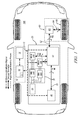
- FIG. 1 schematically shows a diagram of a vehicle including a hybrid powertrain system having an engine, hybrid transmission, torque machine, and a driveline, in accordance with the present disclosure
- FIG. 2 schematically shows details of an electric circuit of a hybrid powertrain system including a high-voltage battery connected to a high-voltage bus connected to an inverter module and first and second torque machines, in accordance with the present disclosure
- FIG. 3 schematically shows a control scheme for controlling operation of an electric circuit for a hybrid powertrain, in accordance with the present disclosure
- FIG. 4 graphically shows simulated operation of a hybrid powertrain system using the control scheme described with reference to FIG. 3 , in accordance with the present disclosure.
- FIG. 1 schematically shows a vehicle 100 including a hybrid powertrain system 20 coupled to a driveline 60 and controlled by a control system 10 .
- the hybrid powertrain system 20 includes a mechanical power path that includes an engine 40 and first and second electrically-powered torque machines (MG A) 35 A and (MG B) 35 B that mechanically couple to a hybrid transmission 50 having an output member 62 that couples to the driveline 60 .
- a high-voltage electrical circuit includes a high-voltage battery 25 that electrically connects to an inverter module 30 via a high-voltage bus 29 .
- the inverter module 30 includes first and second electric power inverters 32 A and 32 B, respectively.
- the engine 40 is preferably a multi-cylinder direct fuel injection internal combustion engine that converts fuel to mechanical power through a combustion process.
- the engine 40 is equipped with a plurality of actuators and sensing devices for monitoring operation and delivering fuel to form a combustion charge to produce torque that is responsive to an operator torque request.
- the engine 40 is configured to operate as a spark-ignition engine with timing of combustion and the associated engine torque being controlled by advancing or retarding spark ignition timing.
- the engine 40 is configured to operate as a compression-ignition engine with timing of combustion and the associated engine torque controlled by advancing or retarding timing of fuel injection events.
- the first and second torque machines 35 A and 35 B preferably include multi-phase electric motor/generators configured to convert stored electric energy to mechanical power and convert mechanical power to electric energy that can be stored in the high-voltage battery 25 .
- the transmission 50 preferably includes one or more differential gear sets and activatable clutch components to effect torque transfer over a range of speeds among the engine 40 , the first and second torque machines 35 A and 35 B, and an output member 62 coupled to a vehicle driveline 60 .
- the driveline 60 can include a differential gear device 65 that mechanically couples to an axle 64 or half-shaft that mechanically couples to a wheel 66 in one embodiment.
- the differential gear device 65 is also coupled to the output member 62 of the hybrid powertrain system 20 .
- the driveline 60 transfers tractive power between the hybrid transmission 50 and a road surface.
- Mechanical power originating in the engine 40 may be transferred via an input member 33 to the first torque machine 35 A and to the output member 62 via the hybrid transmission 50 .
- Mechanical power originating in the first torque machine 35 A may be transferred to the engine 40 via the input member 33 and to the output member 62 via the hybrid transmission 50 .
- Mechanical power originating in the second torque machine 35 B may be transferred via the hybrid transmission 50 to the output member 62 .
- Mechanical power can be transferred between the hybrid transmission 50 and the driveline 60 via the output member 62 .
- Operating parameters associated with such mechanical power transfer include output torque T O and output speed N O .
- the high-voltage battery 25 stores potential electric energy and is electrically connected via a high-voltage bus 29 including a positive side 29 A and a negative side 29 B to the inverter module 30 that connects to the first and second torque machines 35 A and 35 B to transfer electric power therebetween.
- the high-voltage battery 25 is an electric energy storage device that can include a plurality of electrical cells, ultracapacitors, and other devices configured to store electric energy on-vehicle.
- One exemplary high-voltage battery 25 includes a plurality of lithium-ion cells.
- Parametric states associated with the high-voltage battery 25 include a state-of-charge, temperature, available voltage, and available battery power, each of which is monitored by the control system 10 .
- the available battery power describes battery power limits that include an allowable range between a minimum and maximum allowable battery power, described as a maximum charge power (Pbat-Max Charge) and a maximum discharge power (Pbat-Max Discharge). It is appreciated that the battery power is measured in terms of a parameter that can be regularly monitored, e.g., the state-of-charge (SOC) or another suitable parameter.
- the allowable battery power limits are preferably established at threshold levels to prevent either overcharging or overdischarging of the high-voltage battery 25 , which can result in service life reduction thereof.
- the inverter module 30 includes first and second inverters (IMA) 32 A and (IMB) 32 B that electrically connect to the first and second torque machines 35 A and 35 B, respectively.
- the first and second torque machines 35 A and 35 B interact with the respective first and second inverters 32 A and 32 B to convert stored electric energy to mechanical power and convert mechanical power to electric energy that can be stored in the high-voltage battery 25 .
- the first and second electric power inverters 32 A and 32 B are operative to transform high voltage DC electric power to high-voltage AC electric power and also operative to transform high voltage AC electric power to high-voltage DC electric power.
- Electric power originating in the first torque machine 35 A may be transferred electrically to the high-voltage battery 25 via the inverter module 30 and the high-voltage bus 29 and to the second torque machine 35 B via the inverter module 30 .
- Electric power originating in the second torque machine 35 B may be transferred electrically to the high-voltage battery 25 via the inverter module 30 and the high-voltage bus 29 and to the first torque machine 35 A via the inverter module 30 . Additional details related to an exemplary inverter module 30 are provided with reference to FIG. 2 and the associated description.
- the control system 10 includes a control module 12 that is signally connected to an operator interface 14 .
- the control module 12 includes a low-voltage electric power supply to provide regulated electric power thereto. It is appreciated that there is a plurality of human/machine interface devices through which the vehicle operator commands operation of the vehicle 100 , including, e.g., an ignition switch to enable an operator to crank and start the engine 40 , an accelerator pedal, a brake pedal, and a transmission range selector (PRNDL).
- PRNDL transmission range selector
- control module 12 may be combined into one or more devices, e.g., implemented in software, hardware, and/or application-specific integrated circuitry (ASIC) and ancillary circuits that are separate and distinct from the control module 12 . It is appreciated that information transfer to and from the control module 12 can be accomplished using one or more communications paths, e.g., communications bus 18 , which can include one or more of a direct connection, a local area network bus, and a serial peripheral interface bus.
- communications bus 18 can include one or more of a direct connection, a local area network bus, and a serial peripheral interface bus.
- the control module 12 preferably signally and operatively connects to individual elements of the hybrid powertrain system 20 via the communications bus 18 .
- the control module 12 signally connects to the sensing devices of each of the high-voltage battery 25 , the inverter module 30 , the first and second torque machines 35 A and 35 B, the engine 40 , and the hybrid transmission 50 to monitor operation and determine parametric states thereof.
- Monitored parametric states of the engine 40 preferably include engine speed (Ni), engine torque (Ti) or load, and temperature.
- Monitored parametric states of the hybrid transmission 50 preferably include rotational speed, and hydraulic pressure at a plurality of locations, from which parametric states including application of specific torque transfer clutches can be determined
- Monitored parametric states of the torque machine(s) 35 preferably include rotational speeds N A and N B for the respective first and second torque machines 35 A and 35 B.
- Monitored parametric states of the torque machine(s) preferably include power flow(s), e.g., electric current flow, from which a parametric state for motor torques T A and T B , respectively can be determined
- Monitored parametric states of the high-voltage battery 25 include battery power and battery temperature.
- the control module 12 operatively connects to the actuators of each of the inverter module 30 including the first and second inverters 32 A and 32 B, the engine 40 , and the hybrid transmission 50 to control operation thereof in accordance with executed control schemes that are stored in the form of algorithms and calibrations. It is appreciated that each of the first and second inverters 32 A and 32 B transforms electric power in a manner suitable for generating torque with one or both the first and second torque machines 35 A and 35 B, and transforms mechanical power in a manner suitable for generating electric power with one or both the first and second torque machines 35 A and 35 B, depending upon torque inputs and operating conditions.
- the control module 12 executes control schemes to control operation of the engine 40 in coordination with the inverter module 30 to control overall operation of the hybrid powertrain system 20 to manage transfer of mechanical power to the driveline 60 and to manage electric power flow to the high-voltage battery 25 .
- control schemes include balancing operation of the engine 40 with allowable battery power limits associated with the high-voltage battery 25 while achieving an output torque to the driveline 60 that is responsive to an operator torque request. This includes controlling operation of the engine 40 to achieve a preferred engine speed associated with a peak or otherwise preferred efficiency.
- Control module, module, controller, control unit, processor and similar terms mean any suitable one or various combinations of one or more of Application Specific Integrated Circuit(s) (ASIC), electronic circuit(s), central processing unit(s) (preferably microprocessor(s)) and associated memory and storage (read only, programmable read only, random access, hard drive, etc.) executing one or more software or firmware programs, combinational logic circuit(s), input/output circuit(s) and devices, appropriate signal conditioning and buffer circuitry, and other suitable components to provide the described functionality.
- the control module 12 has a set of control algorithms, including resident software program instructions and calibrations stored in memory and executed to provide the desired functions. The algorithms are preferably executed during preset loop cycles.
- Algorithms are executed, such as by a central processing unit, and are operable to monitor inputs from sensing devices and other networked control modules, and execute control and diagnostic routines to control operation of actuators. Loop cycles may be executed at regular intervals, for example each 3.125, 6.25, 12.5, 25 and 100 milliseconds during ongoing engine and vehicle operation. Alternatively, algorithms may be executed in response to occurrence of an event.
- FIG. 2 schematically shows details of an electric circuit including the high-voltage battery 25 , high-voltage bus 29 including the positive side 29 A and the negative side 29 B, the inverter module 30 , and the first and second torque machines 35 A and 35 B.
- a DC link 31 including positive and negative DC link rails 31 A and 31 B, respectively, are coupled to both the first and second inverters 32 A and 32 B.
- a high-voltage filter capacitor 33 is electrically connected between the positive and negative DC links 31 A and 31 B, respectively.
- a controllable discharge switch 34 preferably in series with a resistor element is electrically coupled across the DC link, i.e. between the positive and negative DC link rails 31 A and 31 B.
- a switch device 36 is placed between the positive DC link rail 31 A and the positive side 29 A of the high-voltage bus 29 .
- Negative DC link rail 31 B is directly coupled to the negative side 29 B of the high-voltage bus.
- the switch device 36 may be placed between the negative DC link rail 31 B and the negative side 29 A of the high-voltage bus 29 , and the positive DC link rail 31 A directly coupled to the positive side 29 A of the high-voltage bus.
- One or both the switch device 36 and the discharge switch 34 is controllable to selectively electrically couple and de-couple the high-voltage bus 29 and DC link 31 as described in further functional detail herein below.
- the switch device 36 and the discharge switch 34 are electrically connected to and controlled by the control module 12 .
- the switch device 36 includes a pair of back-to-back power transistors, e.g., IGBT/FWD or MOSFET/FWD devices, connected in parallel to individually control flow of electric current in both directions between the high-voltage battery 25 and the first and second inverters 32 A and 32 B.
- the switch device 36 includes a single power transistor, e.g., an IGBT or a MOSFET device, connected in parallel with a forward-biased diode device.
- the switch device 36 includes a high-speed, high-voltage mechanical switch device.
- the voltage potential across the positive and negative DC link rails 31 A and 31 B across the high-voltage filter capacitor 33 can be used to drive the second torque machine 35 B using the second inverter 32 B to provide tractive torque to the driveline 60 .
- the engine 40 can be used to transfer mechanical power to the first torque machine 35 A.
- the first torque machine 35 A in conjunction with the first inverter 32 A generates electric power using the mechanical power.
- the generated electric power is transferred to the positive and negative DC link rails 31 A and 31 B, and from there to either or both the second inverter 32 A for powering the second torque machine 35 B and the high-voltage bus 29 for charging the high-voltage battery 25 , using energy and torque balancing equations.
- the control scheme for the powertrain system controls and manages electric power in one of a plurality of operating modes, depending upon magnitude of an operator torque request and a capability for the powertrain system 20 to achieve a torque output that is responsive thereto.
- the switch device 36 In a first operating mode, the switch device 36 is in a closed state thus clamping the high-voltage bus 29 to the DC link 31 , and electric power flows between the high-voltage battery 25 and the first and second inverters 32 A and 32 B.
- the DC link voltage i.e., the voltage potential between the positive and negative DC link rails 31 A and 31 B across the high-voltage filter capacitor 33 is equal to the voltage of the high-voltage battery 25 .
- the motor torque output from the second torque machine 35 B is therefore limited to that achievable with the DC link voltage equivalent to the voltage of the high-voltage bus 29 (i.e. the voltage of the high-voltage battery 25 ).
- the switch device 36 In a second operating mode, the switch device 36 is in an open state thus electrically decoupling the high-voltage bus 29 from the DC link 31 , and no electric power flows between the high-voltage battery 25 and the first and second inverters 32 A and 32 B.
- the DC link voltage i.e. the voltage potential between the positive and negative DC link rails 31 A and 31 B
- the voltage potential between the positive and negative DC link rails 31 A and 31 B across the high-voltage filter capacitor 33 is driven by the voltage from the first inverter 32 A based upon input from the first torque machine 35 A as driven by the engine 40 .
- the voltage provided to the second inverter 32 B by the DC link 31 may be greater that the voltage of the high-voltage battery 25 .
- An equivalent motor torque output from the second torque machine 35 B therefore may be achieved at lower motor currents or motor torque output from the second torque machine 35 B may be greater at equivalent motor currents.
- the switch device 36 is cycled between the open state and the closed state, e.g., using a pulsewidth-modulated (PWM) signal with a controllable duty cycle to periodically interrupt electric power flow between the high-voltage battery 25 and the first and second inverters 32 A and 32 B.
- PWM pulsewidth-modulated
- the DC link voltage i.e. the voltage potential between the positive and negative DC link rails 31 A and 31 B, also is not limited to the voltage of the high-voltage battery 25 .
- the voltage potential between the positive and negative DC link rails 31 A and 31 B across the high-voltage filter capacitor 33 is driven by the voltage from the first inverter 32 A based upon input from the first torque machine 35 A as driven by the engine 40 and the duty cycle of the PWM signal to the switch device 36 .
- the voltage provided to the second inverter 32 B by the DC link 31 may be greater that the voltage of the high-voltage battery 25 .
- An equivalent motor torque output from the second torque machine 35 B therefore may be achieved at lower motor currents or motor torque output from the second torque machine 35 B may be greater at equivalent motor currents.
- the motor torque output from the second torque machine 35 B may increase with an increase in the DC link voltage, and may be limited to an upper voltage limit, e.g., 500V DC.
- the energy balance between the first torque machine 35 A and the second torque machine 35 B is mitigated by a periodic energy balance that includes the high-voltage battery 25 .
- FIG. 3 schematically shows a control scheme for controlling operation of a hybrid powertrain, e.g., the hybrid powertrain 20 described with reference to FIGS. 1 and 2 , in response to the operator torque request.
- an operator torque request (TO_REQ) is monitored via the operator interface 14 ( 305 ).
- a preferred DC link voltage (V DC — LINK — PRF ) is determined ( 315 ), for example through calculations or reference, and corresponds to the motor torque command for the second torque machine 35 B transferred to the driveline 60 (T B — CMD ).
- a preferred DC link voltage may, for example, be determined to minimize the electric machine current required to effect the motor torque command and thereby minimize ohmic heating.
- torque generation considerations for second torque machine 35 B may be dominant in the determination of preferred DC link voltage.
- V DC — LINK — PRF a motor torque command for the first torque machine 35 A (T A — CMD ) due to electric energy balance considerations and may be determined with such considerations in mind.
- the DC link voltage (V DC — LINK — MON ) is ongoingly monitored and corresponds to magnitude of voltage from the high-voltage battery 25 at the high-voltage bus 29 (V BAT ) when the high-voltage bus 29 is clamped to the DC link (i.e. switch device 36 closed).
- the DC link voltage (V DC — LINK — MON ) may vary from the voltage from the high-voltage battery 25 at the high-voltage bus 29 (V BAT ) when the high-voltage bus 29 is not clamped to the DC link (i.e., when the switch device 36 open or controlled using a PWM signal with a controllable duty cycle to periodically interrupt electric power flowing between the high-voltage battery 25 ).
- One of the aforementioned first, second, and third operating modes is selected based upon the preferred DC link voltage (V DC — LINK — PRF ), the monitored DC link voltage (V DC — LINK — MON ) and the magnitude of voltage from the high-voltage battery 25 at the high-voltage bus 29 (V BAT ) ( 320 ). Operation of the powertrain system 20 is controlled in the selected one of the first, second, and third operating modes using the switch device 36 to control the DC link voltage (V DC — LINK ) to control electric power flow between the high-voltage battery 25 and the first and second inverters 32 A and 32 B.
- operation of the powertrain system 20 is controlled in the selected one of the first, second, and third operating modes using the discharge switch 34 to control the DC link voltage (V DC — LINK ) to control electric power flow between the high-voltage battery 25 and the first and second inverters 32 A and 32 B.
- V DC — LINK DC link voltage
- the hybrid powertrain system 20 selects the first operating mode (MODE 1) when the preferred DC link voltage (V DC — LINK — PRF ) and the monitored DC link voltage (V DC — LINK — MON ) are equal to or less than the magnitude of voltage from the high-voltage battery 25 at the high-voltage bus 29 (V BAT ).
- the switch device 36 is controlled to the closed state and electric power flows between the high-voltage battery 25 and the first and second inverters 32 A and 32 B via the positive and negative DC link rails 31 A and 31 B.
- the preferred DC link voltage (V DC — LINK — PRF ) is set equal to the voltage from the high-voltage battery 25 at the high-voltage bus 29 (V BAT ).
- the hybrid powertrain system 20 operates in the second operating mode (MODE 2) when the preferred DC link voltage (V DC — LINK — PRF ) is greater than the voltage from the high-voltage battery 25 at the high-voltage bus 29 (V BAT ), and the monitored DC link voltage (V DC — LINK — MON ) is less than an upper voltage limit (V THD ).
- the switch device 36 is controlled in the open state to completely interrupt electric power flowing between the high-voltage battery 25 and the first and second inverters 32 A and 32 B.
- the monitored voltage potential between the positive and negative DC link rails 31 A and 31 B across the high-voltage filter capacitor 33 i.e., the monitored DC link voltage (V DC — LINK — MON ) is driven by the voltage from the first inverter 32 A based upon input from the first torque machine 35 A being driven by the engine 40 .
- Operation in the second operating mode continues so long as the preferred DC link voltage (V DC — LINK — PRF ) is greater than the voltage from the high-voltage battery 25 at the high-voltage bus 29 (V BAT ), and the monitored DC link voltage (V DC — LINK — MON ) is less than the upper voltage limit (V THD ), e.g., 500V DC.
- V THD the upper voltage limit
- the upper voltage limit (V THD ) is associated with design limits and operating capabilities of the various powertrain components, including but not limited to the positive and negative DC link rails 31 A and 31 B, the first and second inverters 32 A and 32 B, and the first and second torque machines 35 A and 35 B.
- the preferred DC link voltage (V DC — LINK — PRF ) is the value previously determined for example through calculations or reference ( 315 ).
- the hybrid powertrain system 20 operates in the third operating mode (Mode 3) when the monitored DC link voltage (V DC — LINK — MON ) is equal to or greater than the upper voltage limit (V THD ).
- Operation in the third operating mode includes controlling the switch device 36 using a PWM signal with a controllable duty cycle to periodically interrupt electric power flowing between the high-voltage battery 25 and the first and second inverters 32 A and 32 B to decrease the monitored DC link voltage (V DC — LINK — MON ) across the filter capacitor 33 .
- operation in the third operating mode includes controlling the discharge switch 34 using the PWM signal with the controllable duty cycle to periodically discharge electric power across the filter capacitor 33 and the first and second inverters 32 A and 32 B to decrease the monitored DC link voltage (V DC — LINK — MON ).
- both the switch device 36 and the discharge switch 34 are controlled using the PWM signal to periodically discharge electric power ( 330 ).
- the monitored voltage potential between the positive and negative DC link rails 31 A and 31 B across the high-voltage filter capacitor 33 i.e., the monitored DC link voltage (V DC — LINK — MON )
- the monitored DC link voltage V DC — LINK — MON
- Operation in the third operating mode continues so long as the monitored DC link voltage (V DC — LINK — MON ) is greater than the upper voltage limit (V THD ).
- the hybrid powertrain system 20 operates in one of the first, second, and third operating modes to control operation of the first and second first torque machines 35 A and 35 B in response to the operator torque request ( 325 ).
- a preferred control scheme includes determining the preferred DC link voltage (V DC — LINK — PRF ) and the motor torque command for the second torque machine 35 B transferred to the driveline 60 (T B — CMD ), as previously described.
- Monitored states of the hybrid powertrain system 20 include a present rotational speed (N A ) of the first torque machine 35 A and the monitored DC link voltage (V DC — LINK — MON ).
- a proportional (P) and integral (I) control logic is executed to determine a motor torque command for the first torque machine 35 A (T A — CMD ) in response to the present rotational speed (N A ) of the first torque machine 35 A and a difference between the monitored DC link voltage (V DC — LINK — MON ) and the preferred DC link voltage (V DC — LINK — PRF ).
- Torque balancing is executed between the motor torque command for the first torque machine 35 A (T A — CMD ) and the motor torque command for the second torque machine 35 B (T B — CMD ) to determine final motor torque commands for the first and second torque machines 35 A and 35 B, i.e., T A — FINAL and T B — FINAL ,respectively.
- FIG. 4 graphically shows simulated operation of the hybrid powertrain system 20 using the control scheme described with reference to FIG. 3 , including controlling the switch device 36 to maintain the monitored DC link voltage (V DC — LINK — MON ) at or below the upper voltage limit (V THD ) and maintaining balanced torque output from the first and second torque machines 35 A and 35 B respectively.
- V DC — LINK — MON monitored DC link voltage
- V THD upper voltage limit
Landscapes
- Engineering & Computer Science (AREA)
- Transportation (AREA)
- Mechanical Engineering (AREA)
- Power Engineering (AREA)
- Combustion & Propulsion (AREA)
- Chemical & Material Sciences (AREA)
- Life Sciences & Earth Sciences (AREA)
- Sustainable Development (AREA)
- Sustainable Energy (AREA)
- Automation & Control Theory (AREA)
- Electric Propulsion And Braking For Vehicles (AREA)
- Hybrid Electric Vehicles (AREA)
- Dc-Dc Converters (AREA)
Abstract
Description
Claims (16)
Priority Applications (3)
| Application Number | Priority Date | Filing Date | Title |
|---|---|---|---|
| US12/874,551 US8860348B2 (en) | 2010-09-02 | 2010-09-02 | Method and apparatus for controlling a high-voltage battery connection for hybrid powertrain system |
| DE102011110906.8A DE102011110906B4 (en) | 2010-09-02 | 2011-08-18 | Method of operating a hybrid powertrain system and hybrid powertrain system |
| CN201110258190.3A CN102398507B (en) | 2010-09-02 | 2011-09-02 | For controlling the method and apparatus that the high-tension battery of hybrid powertrain system connects |
Applications Claiming Priority (1)
| Application Number | Priority Date | Filing Date | Title |
|---|---|---|---|
| US12/874,551 US8860348B2 (en) | 2010-09-02 | 2010-09-02 | Method and apparatus for controlling a high-voltage battery connection for hybrid powertrain system |
Publications (2)
| Publication Number | Publication Date |
|---|---|
| US20120056567A1 US20120056567A1 (en) | 2012-03-08 |
| US8860348B2 true US8860348B2 (en) | 2014-10-14 |
Family
ID=45595613
Family Applications (1)
| Application Number | Title | Priority Date | Filing Date |
|---|---|---|---|
| US12/874,551 Active 2033-01-27 US8860348B2 (en) | 2010-09-02 | 2010-09-02 | Method and apparatus for controlling a high-voltage battery connection for hybrid powertrain system |
Country Status (3)
| Country | Link |
|---|---|
| US (1) | US8860348B2 (en) |
| CN (1) | CN102398507B (en) |
| DE (1) | DE102011110906B4 (en) |
Cited By (5)
| Publication number | Priority date | Publication date | Assignee | Title |
|---|---|---|---|---|
| US20130234510A1 (en) * | 2012-03-09 | 2013-09-12 | Yasushi Nakamura | Electric vehicle inverter device |
| US20150298630A1 (en) * | 2012-08-29 | 2015-10-22 | Honda Access Corp. | System for monitoring battery provided in vehicle |
| US20160207402A1 (en) * | 2013-09-24 | 2016-07-21 | Toyota Jidosha Kabushiki Kaisha | Power supply system |
| CN108068625A (en) * | 2016-11-16 | 2018-05-25 | 福特全球技术公司 | The operation of power electronics during battery communication loss |
| US10836371B1 (en) * | 2019-10-11 | 2020-11-17 | Ford Global Technologies, Llc | Battery saving controls associated with mobile generator use of a vehicle |
Families Citing this family (16)
| Publication number | Priority date | Publication date | Assignee | Title |
|---|---|---|---|---|
| US8653841B2 (en) | 2012-05-04 | 2014-02-18 | GM Global Technology Operations LLC | Method and apparatus for monitoring a high-voltage electrical circuit including a discharge circuit |
| US20140228166A1 (en) * | 2013-02-12 | 2014-08-14 | GM Global Technology Operations LLC | Method and apparatus for controlling motor torques in a multi-mode powertrain system |
| US9470739B2 (en) * | 2013-11-12 | 2016-10-18 | Ford Global Technologies, Llc | DC link capacitance measurement for electric vehicle drivetrain |
| US9956931B2 (en) * | 2014-04-03 | 2018-05-01 | Ford Global Technologies, Llc | Electrical power system for hybrid vehicles |
| US9643552B2 (en) * | 2014-04-03 | 2017-05-09 | Ford Global Technologies, Llc | Electrical power system for hybrid vehicles |
| US9484852B2 (en) * | 2014-04-07 | 2016-11-01 | Fca Us Llc | High power low voltage electrified powertrain |
| CN105785136B (en) * | 2014-12-19 | 2020-10-23 | 福特全球技术公司 | Direct current link capacitance measurement for electric vehicle drive train |
| US10528023B2 (en) * | 2016-12-22 | 2020-01-07 | General Dynamics-OTS. Inc. | Electric motor drive system for low-voltage motor |
| DE102019212351A1 (en) | 2019-08-19 | 2021-02-25 | Robert Bosch Gmbh | Battery system for a motor vehicle, method for operating a battery system and motor vehicle |
| DE102019212475A1 (en) | 2019-08-21 | 2021-02-25 | Robert Bosch Gmbh | Battery system for a motor vehicle, method for operating a battery system and motor vehicle |
| DE102019212473A1 (en) * | 2019-08-21 | 2021-02-25 | Robert Bosch Gmbh | Battery system for a motor vehicle, method for operating a battery system and motor vehicle |
| US11345253B2 (en) * | 2019-09-19 | 2022-05-31 | Nio Usa, Inc. | Vehicle power devices, systems, and methods for fail operational electronic control unit power management |
| DE102020114204A1 (en) | 2020-05-27 | 2021-12-02 | Schaeffler Technologies AG & Co. KG | Active discharge of a vehicle intermediate circuit element with pulse width modulation |
| US11752878B2 (en) | 2020-09-28 | 2023-09-12 | GM Global Technology Operations LLC | Method and apparatus for controlling a multi-mode powertrain system of a vehicle |
| DE102021115390B4 (en) | 2021-06-15 | 2023-04-27 | Schaeffler Technologies AG & Co. KG | Active discharge of a vehicle intermediate circuit element with a discrete discharge circuit generating PWM pulses |
| DE102021208781A1 (en) | 2021-08-11 | 2023-02-16 | Zf Friedrichshafen Ag | Discharge circuit for an intermediate circuit capacitor in an inverter; Inverter with such a discharge circuit |
Citations (13)
| Publication number | Priority date | Publication date | Assignee | Title |
|---|---|---|---|---|
| US5373195A (en) | 1992-12-23 | 1994-12-13 | General Electric Company | Technique for decoupling the energy storage system voltage from the DC link voltage in AC electric drive systems |
| US6048289A (en) * | 1998-03-30 | 2000-04-11 | Nissan Motor Co., Ltd. | Hybrid vehicle |
| US20040145338A1 (en) * | 2001-12-26 | 2004-07-29 | Makoto Nakamura | Electric load apparatus electric load controlling method and computer readable recording medium recording program for causing computer to execute control of electric load |
| US7135835B2 (en) | 2004-08-10 | 2006-11-14 | Fanuc Ltd | Converter apparatus, inverter apparatus, and DC link voltage control method |
| US7176648B2 (en) * | 2004-05-18 | 2007-02-13 | Husky Injection Molding Systems Ltd. | Energy management apparatus and method for injection molding systems |
| US20070171689A1 (en) * | 2004-01-13 | 2007-07-26 | Toyota Jidosha Kabushiki Kaisha | Ac voltage generating apparatus and motive power outputting apparatus |
| US20090058326A1 (en) * | 2005-09-01 | 2009-03-05 | Toyota Jidosha Kabushiki Kaisha | Hybrid vehicle and method of controlling the same |
| US7538449B2 (en) | 2005-04-08 | 2009-05-26 | Semikron Elektronik Gmbh & Co. Kg | Circuitry and related control method for an electric or hybrid vehicle with two direct current sources |
| US20110095603A1 (en) * | 2009-10-27 | 2011-04-28 | Hyundai Motor Company | Emergency control apparatus and method for use |
| US20110115416A1 (en) * | 2009-11-13 | 2011-05-19 | Lg Electronics Inc. | Apparatus for driving motor of electric vehicle |
| US8110948B2 (en) * | 2008-04-03 | 2012-02-07 | Ut-Battelle, Llc | Power conversion apparatus and method |
| US8169177B2 (en) * | 2007-03-26 | 2012-05-01 | Toyota Jidosha Kabushiki Kaisha | Electric vehicle |
| US8281886B2 (en) * | 2007-11-01 | 2012-10-09 | Aisin Aw Co., Ltd. | Electric motor control device, drive device and hybrid drive device |
Family Cites Families (4)
| Publication number | Priority date | Publication date | Assignee | Title |
|---|---|---|---|---|
| US6608396B2 (en) * | 2001-12-06 | 2003-08-19 | General Motors Corporation | Electrical motor power management system |
| CN100361361C (en) * | 2003-04-02 | 2008-01-09 | 宁波宝鑫铁路信号设备制造有限公司 | Intelligent railway signal power source switching module |
| US7457092B2 (en) * | 2005-12-07 | 2008-11-25 | Alpha & Omega Semiconductor, Lld. | Current limited bilateral MOSFET switch with reduced switch resistance and lower manufacturing cost |
| CN201457025U (en) * | 2009-04-10 | 2010-05-12 | 北汽福田汽车股份有限公司 | Hybrid power system and vehicle provided with same |
-
2010
- 2010-09-02 US US12/874,551 patent/US8860348B2/en active Active
-
2011
- 2011-08-18 DE DE102011110906.8A patent/DE102011110906B4/en active Active
- 2011-09-02 CN CN201110258190.3A patent/CN102398507B/en active Active
Patent Citations (13)
| Publication number | Priority date | Publication date | Assignee | Title |
|---|---|---|---|---|
| US5373195A (en) | 1992-12-23 | 1994-12-13 | General Electric Company | Technique for decoupling the energy storage system voltage from the DC link voltage in AC electric drive systems |
| US6048289A (en) * | 1998-03-30 | 2000-04-11 | Nissan Motor Co., Ltd. | Hybrid vehicle |
| US20040145338A1 (en) * | 2001-12-26 | 2004-07-29 | Makoto Nakamura | Electric load apparatus electric load controlling method and computer readable recording medium recording program for causing computer to execute control of electric load |
| US20070171689A1 (en) * | 2004-01-13 | 2007-07-26 | Toyota Jidosha Kabushiki Kaisha | Ac voltage generating apparatus and motive power outputting apparatus |
| US7176648B2 (en) * | 2004-05-18 | 2007-02-13 | Husky Injection Molding Systems Ltd. | Energy management apparatus and method for injection molding systems |
| US7135835B2 (en) | 2004-08-10 | 2006-11-14 | Fanuc Ltd | Converter apparatus, inverter apparatus, and DC link voltage control method |
| US7538449B2 (en) | 2005-04-08 | 2009-05-26 | Semikron Elektronik Gmbh & Co. Kg | Circuitry and related control method for an electric or hybrid vehicle with two direct current sources |
| US20090058326A1 (en) * | 2005-09-01 | 2009-03-05 | Toyota Jidosha Kabushiki Kaisha | Hybrid vehicle and method of controlling the same |
| US8169177B2 (en) * | 2007-03-26 | 2012-05-01 | Toyota Jidosha Kabushiki Kaisha | Electric vehicle |
| US8281886B2 (en) * | 2007-11-01 | 2012-10-09 | Aisin Aw Co., Ltd. | Electric motor control device, drive device and hybrid drive device |
| US8110948B2 (en) * | 2008-04-03 | 2012-02-07 | Ut-Battelle, Llc | Power conversion apparatus and method |
| US20110095603A1 (en) * | 2009-10-27 | 2011-04-28 | Hyundai Motor Company | Emergency control apparatus and method for use |
| US20110115416A1 (en) * | 2009-11-13 | 2011-05-19 | Lg Electronics Inc. | Apparatus for driving motor of electric vehicle |
Cited By (9)
| Publication number | Priority date | Publication date | Assignee | Title |
|---|---|---|---|---|
| US20130234510A1 (en) * | 2012-03-09 | 2013-09-12 | Yasushi Nakamura | Electric vehicle inverter device |
| US20150298630A1 (en) * | 2012-08-29 | 2015-10-22 | Honda Access Corp. | System for monitoring battery provided in vehicle |
| US9849850B2 (en) * | 2012-08-29 | 2017-12-26 | Honda Access Corp. | System for monitoring battery provided in vehicle |
| US20160207402A1 (en) * | 2013-09-24 | 2016-07-21 | Toyota Jidosha Kabushiki Kaisha | Power supply system |
| US9783058B2 (en) * | 2013-09-24 | 2017-10-10 | Toyota Jidosha Kabushiki Kaisha | Power supply system |
| CN108068625A (en) * | 2016-11-16 | 2018-05-25 | 福特全球技术公司 | The operation of power electronics during battery communication loss |
| US10286899B2 (en) * | 2016-11-16 | 2019-05-14 | Ford Global Technologies, Llc | Operation of power electronics during battery communication loss |
| CN108068625B (en) * | 2016-11-16 | 2023-02-28 | 福特全球技术公司 | Operation of power electronics during loss of battery communication |
| US10836371B1 (en) * | 2019-10-11 | 2020-11-17 | Ford Global Technologies, Llc | Battery saving controls associated with mobile generator use of a vehicle |
Also Published As
| Publication number | Publication date |
|---|---|
| US20120056567A1 (en) | 2012-03-08 |
| DE102011110906B4 (en) | 2022-06-15 |
| CN102398507B (en) | 2016-08-17 |
| DE102011110906A1 (en) | 2012-03-08 |
| CN102398507A (en) | 2012-04-04 |
Similar Documents
| Publication | Publication Date | Title |
|---|---|---|
| US8860348B2 (en) | Method and apparatus for controlling a high-voltage battery connection for hybrid powertrain system | |
| CN111452670B (en) | Battery voltage switching system and control logic for a multi-battery electrically driven vehicle | |
| JP5899274B2 (en) | Hybrid vehicle and control method thereof | |
| JP6681002B2 (en) | Power control device for hybrid vehicle | |
| US8543271B2 (en) | Power supply system for electrically powered vehicle, and method for controlling the same | |
| JP5011940B2 (en) | Power supply device and vehicle | |
| US8624426B2 (en) | Power supply system for electrically powered vehicle, electrically powered vehicle, and method for controlling power supply system of electrically powered vehicle | |
| JP5624995B2 (en) | Hybrid vehicle and control method thereof | |
| US7567061B2 (en) | Battery equalization using a plug-in charger in a hybrid electric vehicle | |
| US10059223B2 (en) | Power supply control apparatus and power supply control method | |
| US9873339B2 (en) | Vehicle, power source system, and control method of power source system | |
| US20160129796A1 (en) | Power supply system of electric-powered vehicle | |
| CN109624962B (en) | Hybrid vehicle | |
| WO2014109064A1 (en) | Hybrid vehicle and method for controlling same | |
| JP2008017661A (en) | Power supply system, vehicle equipped therewith, control method thereof, and computer-readable recording medium recorded with program for executing control thereof by computer | |
| US20130293248A1 (en) | Method and apparatus for monitoring a high-voltage electrical circuit including a discharge circuit | |
| CN111319513B (en) | Battery system, electric vehicle, and method for controlling electric vehicle | |
| US9145131B2 (en) | Vehicle and vehicle control method | |
| JP5676227B2 (en) | Motor control apparatus and method for hybrid vehicle | |
| JP6967633B2 (en) | Vehicle control device | |
| JP6531130B2 (en) | Control device for hybrid vehicle | |
| US20150015064A1 (en) | Boost converter deadtime compensation | |
| WO2014038442A1 (en) | Hybrid vehicle control apparatus | |
| JP2012170300A (en) | Electric vehicle and voltage control method therefor | |
| JPH11122709A (en) | Hybrid electric car |
Legal Events
| Date | Code | Title | Description |
|---|---|---|---|
| AS | Assignment |
Owner name: GM GLOBAL TECHNOLOGY OPERATIONS, INC., MICHIGAN Free format text: ASSIGNMENT OF ASSIGNORS INTEREST;ASSIGNORS:SAVAGIAN, PETER J.;GLEASON, SEAN E.;TARCHINSKI, JAMES E.;AND OTHERS;SIGNING DATES FROM 20100802 TO 20100810;REEL/FRAME:024931/0145 |
|
| AS | Assignment |
Owner name: WILMINGTON TRUST COMPANY, DELAWARE Free format text: SECURITY AGREEMENT;ASSIGNOR:GM GLOBAL TECHNOLOGY OPERATIONS, INC.;REEL/FRAME:025324/0658 Effective date: 20101027 |
|
| AS | Assignment |
Owner name: GM GLOBAL TECHNOLOGY OPERATIONS LLC, MICHIGAN Free format text: CHANGE OF NAME;ASSIGNOR:GM GLOBAL TECHNOLOGY OPERATIONS, INC.;REEL/FRAME:025781/0333 Effective date: 20101202 |
|
| FEPP | Fee payment procedure |
Free format text: PAYOR NUMBER ASSIGNED (ORIGINAL EVENT CODE: ASPN); ENTITY STATUS OF PATENT OWNER: LARGE ENTITY |
|
| STCF | Information on status: patent grant |
Free format text: PATENTED CASE |
|
| AS | Assignment |
Owner name: GM GLOBAL TECHNOLOGY OPERATIONS LLC, MICHIGAN Free format text: RELEASE BY SECURED PARTY;ASSIGNOR:WILMINGTON TRUST COMPANY;REEL/FRAME:034287/0159 Effective date: 20141017 |
|
| MAFP | Maintenance fee payment |
Free format text: PAYMENT OF MAINTENANCE FEE, 4TH YEAR, LARGE ENTITY (ORIGINAL EVENT CODE: M1551) Year of fee payment: 4 |
|
| MAFP | Maintenance fee payment |
Free format text: PAYMENT OF MAINTENANCE FEE, 8TH YEAR, LARGE ENTITY (ORIGINAL EVENT CODE: M1552); ENTITY STATUS OF PATENT OWNER: LARGE ENTITY Year of fee payment: 8 |