US8858031B2 - Light engine device with direct to linear system driver - Google Patents
Light engine device with direct to linear system driver Download PDFInfo
- Publication number
- US8858031B2 US8858031B2 US13/188,029 US201113188029A US8858031B2 US 8858031 B2 US8858031 B2 US 8858031B2 US 201113188029 A US201113188029 A US 201113188029A US 8858031 B2 US8858031 B2 US 8858031B2
- Authority
- US
- United States
- Prior art keywords
- lighting
- lighting device
- substrate
- light
- housing component
- Prior art date
- Legal status (The legal status is an assumption and is not a legal conclusion. Google has not performed a legal analysis and makes no representation as to the accuracy of the status listed.)
- Expired - Fee Related, expires
Links
Images


Classifications
-
- F21V9/17—
-
- F—MECHANICAL ENGINEERING; LIGHTING; HEATING; WEAPONS; BLASTING
- F21—LIGHTING
- F21K—NON-ELECTRIC LIGHT SOURCES USING LUMINESCENCE; LIGHT SOURCES USING ELECTROCHEMILUMINESCENCE; LIGHT SOURCES USING CHARGES OF COMBUSTIBLE MATERIAL; LIGHT SOURCES USING SEMICONDUCTOR DEVICES AS LIGHT-GENERATING ELEMENTS; LIGHT SOURCES NOT OTHERWISE PROVIDED FOR
- F21K9/00—Light sources using semiconductor devices as light-generating elements, e.g. using light-emitting diodes [LED] or lasers
- F21K9/20—Light sources comprising attachment means
- F21K9/27—Retrofit light sources for lighting devices with two fittings for each light source, e.g. for substitution of fluorescent tubes
-
- F21S4/008—
-
- F—MECHANICAL ENGINEERING; LIGHTING; HEATING; WEAPONS; BLASTING
- F21—LIGHTING
- F21S—NON-PORTABLE LIGHTING DEVICES; SYSTEMS THEREOF; VEHICLE LIGHTING DEVICES SPECIALLY ADAPTED FOR VEHICLE EXTERIORS
- F21S4/00—Lighting devices or systems using a string or strip of light sources
- F21S4/20—Lighting devices or systems using a string or strip of light sources with light sources held by or within elongate supports
- F21S4/28—Lighting devices or systems using a string or strip of light sources with light sources held by or within elongate supports rigid, e.g. LED bars
-
- F—MECHANICAL ENGINEERING; LIGHTING; HEATING; WEAPONS; BLASTING
- F21—LIGHTING
- F21V—FUNCTIONAL FEATURES OR DETAILS OF LIGHTING DEVICES OR SYSTEMS THEREOF; STRUCTURAL COMBINATIONS OF LIGHTING DEVICES WITH OTHER ARTICLES, NOT OTHERWISE PROVIDED FOR
- F21V19/00—Fastening of light sources or lamp holders
- F21V19/001—Fastening of light sources or lamp holders the light sources being semiconductors devices, e.g. LEDs
- F21V19/003—Fastening of light source holders, e.g. of circuit boards or substrates holding light sources
-
- F—MECHANICAL ENGINEERING; LIGHTING; HEATING; WEAPONS; BLASTING
- F21—LIGHTING
- F21V—FUNCTIONAL FEATURES OR DETAILS OF LIGHTING DEVICES OR SYSTEMS THEREOF; STRUCTURAL COMBINATIONS OF LIGHTING DEVICES WITH OTHER ARTICLES, NOT OTHERWISE PROVIDED FOR
- F21V21/00—Supporting, suspending, or attaching arrangements for lighting devices; Hand grips
- F21V21/14—Adjustable mountings
- F21V21/30—Pivoted housings or frames
-
- F—MECHANICAL ENGINEERING; LIGHTING; HEATING; WEAPONS; BLASTING
- F21—LIGHTING
- F21V—FUNCTIONAL FEATURES OR DETAILS OF LIGHTING DEVICES OR SYSTEMS THEREOF; STRUCTURAL COMBINATIONS OF LIGHTING DEVICES WITH OTHER ARTICLES, NOT OTHERWISE PROVIDED FOR
- F21V23/00—Arrangement of electric circuit elements in or on lighting devices
- F21V23/003—Arrangement of electric circuit elements in or on lighting devices the elements being electronics drivers or controllers for operating the light source, e.g. for a LED array
- F21V23/007—Arrangement of electric circuit elements in or on lighting devices the elements being electronics drivers or controllers for operating the light source, e.g. for a LED array enclosed in a casing
- F21V23/008—Arrangement of electric circuit elements in or on lighting devices the elements being electronics drivers or controllers for operating the light source, e.g. for a LED array enclosed in a casing the casing being outside the housing of the lighting device
-
- F—MECHANICAL ENGINEERING; LIGHTING; HEATING; WEAPONS; BLASTING
- F21—LIGHTING
- F21V—FUNCTIONAL FEATURES OR DETAILS OF LIGHTING DEVICES OR SYSTEMS THEREOF; STRUCTURAL COMBINATIONS OF LIGHTING DEVICES WITH OTHER ARTICLES, NOT OTHERWISE PROVIDED FOR
- F21V29/00—Protecting lighting devices from thermal damage; Cooling or heating arrangements specially adapted for lighting devices or systems
- F21V29/50—Cooling arrangements
- F21V29/70—Cooling arrangements characterised by passive heat-dissipating elements, e.g. heat-sinks
- F21V29/74—Cooling arrangements characterised by passive heat-dissipating elements, e.g. heat-sinks with fins or blades
- F21V29/77—Cooling arrangements characterised by passive heat-dissipating elements, e.g. heat-sinks with fins or blades with essentially identical diverging planar fins or blades, e.g. with fan-like or star-like cross-section
- F21V29/777—Cooling arrangements characterised by passive heat-dissipating elements, e.g. heat-sinks with fins or blades with essentially identical diverging planar fins or blades, e.g. with fan-like or star-like cross-section the planes containing the fins or blades having directions perpendicular to the light emitting axis
-
- F21Y2101/02—
-
- F—MECHANICAL ENGINEERING; LIGHTING; HEATING; WEAPONS; BLASTING
- F21—LIGHTING
- F21Y—INDEXING SCHEME ASSOCIATED WITH SUBCLASSES F21K, F21L, F21S and F21V, RELATING TO THE FORM OR THE KIND OF THE LIGHT SOURCES OR OF THE COLOUR OF THE LIGHT EMITTED
- F21Y2115/00—Light-generating elements of semiconductor light sources
- F21Y2115/10—Light-emitting diodes [LED]
Definitions
- the present invention generally relates to light emitting diode (LED) lighting technology. Specifically, the present invention relates to a system of linear light engine devices utilizing independent and external power supplies for each linear device.
- LED light emitting diode
- fluorescent fixtures Many offices and businesses utilize fluorescent lights to extensively illuminate large areas of buildings, thereby eliminating the need for using several small lights.
- traditional fluorescent lights are inefficient and may require great amounts of electrical energy to produce light. This is problematic, as large buildings may contain many fluorescent light fixtures that remain on for long periods of time, leading to a significant waste in energy.
- fluorescent fixtures have tombstone brackets, which carry the electrical circuit to power the fluorescent lights. These tombstones are vulnerable to arcing and restrict the ability to rotate the fluorescent lights, which would break the electrical circuit.
- An embodiment of the present invention provides a light engine lighting device formed on a substrate and contained within a linear system.
- the light engine lighting device is an LED linear device, also referred to herein as an “LED tube”.
- the light engine lighting device is powered by an externally located, constant current power supply, which is electrically connected to a power terminal of the light engine lighting device via an opening in the linear system.
- independent and external power supplies for each of the light engine lighting devices are used, thereby providing for rotational independence among each light engine lighting device.
- a first aspect of an exemplary embodiment of the present invention provides a lighting system which includes a lighting device and a power supply driver.
- the lighting device includes a plurality of light-emitting elements and a power terminal.
- the power supply driver is electrically coupled to the power terminal to provide power to the plurality of light-emitting elements.
- the power supply driver is located external to the lighting device.
- a second aspect of an exemplary embodiment of the present invention provides a lighting device which includes a substrate, a plurality of light-emitting elements coupled to the substrate, and a power terminal configured to be coupled to a power supply driver.
- the power supply driver is located external to the lighting device.
- a third aspect of an exemplary embodiment of the present invention provides a lighting control system including at least one lighting system and at least one controller.
- the at least one lighting system has at least a first lighting device powered by a first power supply and a second lighting device powered by a second power supply.
- the at least one controller is coupled to the at least one lighting system for controlling operation of the first and second lighting devices.
- FIG. 1 depicts a side perspective view of an exemplary embodiment of a lighting system comprising one lighting device comprising a heat sink and a substrate having one or more light-emitting elements, in accordance with an exemplary embodiment of the present invention.
- FIG. 2 depicts a cross-sectional view of the lighting system of FIG. 1 , in accordance with an exemplary embodiment of the present invention.
- FIG. 3 depicts a cross-sectional view of another exemplary embodiment of a lighting system comprising a plurality of lighting devices, each casting a light cone, in accordance with an exemplary embodiment of the present invention.
- FIG. 4 depicts a cross-sectional view of the lighting system of FIG. 3 in which one of the lighting devices is rotated to rotate the light cone projected by the rotated lighting device, in accordance with an exemplary embodiment of the present invention.
- FIG. 5 depicts a side view of rotational device configured to connect the light device of FIG. 1 to a conventional fluorescent tube fixture, in accordance with an exemplary embodiment of the present invention.
- FIG. 5A depicts an exemplary fixture for mounting the lighting systems of FIGS. 1 and 3 , in accordance with an exemplary embodiment of the present invention.
- FIG. 6 depicts a cross-sectional view of the rotational device of FIG. 5 , in accordance with an exemplary embodiment of the present invention.
- FIG. 7 depicts a cross-sectional view of a plurality of lighting devices installed in an exemplary parking structure, in accordance with an exemplary embodiment of the present invention.
- FIGS. 8A-8D illustrate various rotational positions of the lighting devices of the lighting system of FIG. 3 , in accordance with an exemplary embodiment of the present invention.
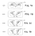
- FIGS. 9A-9D illustrate various additional rotational positions of the lighting devices of the lighting system of FIG. 3 equipped with a reflector, in accordance with an exemplary embodiment of the present invention.
- FIGS. 10A-10D illustrate various means for securing the substrate to the heat sink of the lighting device of FIG. 1 , in accordance with an exemplary embodiment of the present invention.
- FIGS. 11A-11C illustrate alternative embodiments of the heat sink of the lighting device of FIG. 1 , in accordance with an exemplary embodiment of the present invention.
- FIGS. 12A-12C illustrate various embodiments of a lens configured for covering the one or more light-emitting elements of the lighting device of FIG. 1 , in accordance with an exemplary embodiment of the present invention.
- FIGS. 13A and 13B illustrate additional embodiments of the lens of FIG. 12C , in accordance with an exemplary embodiment of the present invention.
- FIGS. 14 and 15 illustrate additional embodiments of the lighting device of FIG. 1 , in which the heat sink provides for securing a plurality of light-emitting elements for casting light cones in more than one direction, in accordance with an exemplary embodiment of the present invention.
- FIG. 16 illustrates a control system for controlling the plurality of lighting devices installed in the parking structure of FIG. 7 , in accordance with an exemplary embodiment of the present invention.
- LED lighting systems have been developed to increase efficiency over traditional fluorescent tubes.
- a drawback of such LED lighting systems is the excessive heat that is typically generated by the LEDs. Such heat causes the layers of phosphor within the LEDs to degrade. Furthermore, heat generated by power sources in close proximity to the LEDs melts the layers of phosphor and, as a result, changes the color emitted by the LEDs. The result after continuous degradation is that the LEDs emit light appearing as blue-white rather than the neutral or warm white emitted by non-degraded chips.
- LEDs disposed in a tube near an internal, dependent power supply may develop burn marks. These burn marks are seen as a drop off in output.
- LEDs not degraded may output light at 300 foot-candles (fc), and LEDs in a damaged area may only output light at 150 fc at the edge of the burn zone and at 110 fc at the center of the burn zone.
- the burn zone is typically at least as long as the length of the internal dependent power supply.
- the burn zone may be at least 4 to 5 inches long, or approximately 10% of an overall 48-inch tube.
- An exemplary embodiment of the present invention provides a lighting system comprising one or more lighting devices, each comprising one or more light-emitting elements mounted onto a substrate mounted within the lighting device.
- Each light-emitting element is powered by an externally located, constant current power supply, which is directly connected to the light-emitting element via a power terminal.
- the lighting system is mounted within a fixture and comprises a plurality of lighting devices and a plurality of independent power supplies, each of which is connected to a respective one of the plurality of lighting devices.
- each lighting device is independently powered for providing independent, configurable lighting.
- each lighting device may be rotatably mounted within the fixture and configured for complete rotational independence, thereby providing a variety of configurable lighting conditions.
- Exemplary applications of the lighting system include offices, homes, parking garages, etc., which applications are designed to provide buildings with an alternative lighting arrangement to less efficient fluorescent tube lighting.
- Exemplary light-emitting elements in the exemplary embodiments of the present invention described here include LEDs, light emitting capacitors (LECs), and organic LEDs (OLEDs).
- the lighting system 10 comprises a lighting device 14 which comprises a linear substrate 12 .
- the lighting device 14 further comprises a plurality of light-emitting elements 18 and a power terminal 20 coupled to the plurality of light-emitting elements 18 .
- the light-emitting elements 18 are disposed in a linear relationship along the substrate 12 .
- the lighting device 14 is a linear device or system 16 as the substrate 12 is linear and the light-emitting elements 18 are disposed along the substrate 12 linearly.
- the lighting device 14 is so configured so that it may be dropped into existing fluorescent-tube lighting fixtures without adapters or, optionally, with rotational end caps, as described below. It is to be understood, however, that the lighting device 14 is not limited to being a linear device 16 . Other geometric configurations are contemplated, such as circular or toroid, U-shaped, etc.
- the system 10 further comprises a power supply driver 22 electrically connected to the power terminal 20 by a set of wires 24 .
- the power supply driver 22 converts A/C line electricity to D/C electricity and delivers the D/C electricity to the light-emitting elements 18 via the wires 24 .
- the wires 24 protrude through an opening in the lighting device 14 for connecting the power supply driver 22 to the power terminal 20 .
- the power supply driver 22 is located external to the lighting device 14 . By being so disposed, heat from the power supply driver 22 is isolated from the lighting device 14 and, therefore, burn marks on the lighting device 14 are minimized. It is to be understood that other embodiments in which the power supply driver 22 is located inside the lighting device 14 are contemplated.
- the system 10 additionally comprises a heat sink 26 for removing heat from the lighting device 14 .
- the heat sink 26 may comprise a linear thermal management heat sink of any material type or configuration for passive or active cooling.
- the heat sink 26 may primarily be a flat plate, die-cast finned type, or extruded finned type.
- Materials used to form the heat sink 26 may include aluminum, copper, and some other types of materials with sufficient heat conductivity.
- the heat sink 26 may comprises a plurality of radially extending fins, the outer periphery of which form a semi-circular shape in cross section, as illustrated in FIG. 2 .
- Other embodiments of the heat sink 26 including ones including linearly extending fins, are contemplated.
- each light-emitting element 18 is an LED.
- Such LEDs may be discrete components packaged in conventional 5 mm epoxy cylindrical packages, or they may be surface-mounted packaged dies or bare (unpackaged) dies. It is contemplated, however, that the light-emitting elements are not limited to being LEDs. Alternative embodiments in which the light-emitting elements 18 are light emitting capacitors (LECs) or organic LEDs are contemplated.
- LECs light emitting capacitors
- the substrate 12 is a board and the light-emitting elements 18 are bare (unpackaged) dies mounted on the board and wire bonded.
- the substrate 12 is a flex substrate laminated with flex circuitry are contemplated. It is to be understood that each component of the lighting device 14 can be manufactured in various lengths and dimensions as necessary to allow the lighting device 14 to fit into a conventional lighting fixture, e.g., a fluorescent tube fixture.
- the lighting device 14 further comprises a lens 30 which covers and protects the substrate 12 and the light-emitting elements 18 disposed thereon.
- the lens 30 is not illustrated in FIG. 1 to provide a clearer view of the substrate 12 and the light-emitting elements 18 disposed thereon.
- the cross-sectional view illustrated in FIG. 2 shows the wiring connection 24 between the lighting device 14 and the power supply driver 22 .
- the wiring 24 connects to the power terminal 20 of the lighting device 14 through an opening 28 in the lens 30 .
- Other embodiments of the path of the wiring 24 are contemplated.
- the wiring 24 may alternatively protrude through an opening in the heat sink 26 or through an opening in a rotational device (illustrated in FIG. 5 ) secured to an end of the lighting device 14 .
- the power supply driver 22 comprises a fastener 32 for removable connection to the wiring 24 .
- the fastener 32 allows the power supply driver 22 to be removed and replaced for easier installation and/or repair.
- Exemplary applications of the lighting device 14 include use as a retrofit replacement to a conventional fluorescent tube system.
- a fluorescent tube system comprises one or more fluorescent tubes, each of which is mounted in a fixture between a pair of tombstone assemblies.
- Each tombstone assembly includes a socket bar, a lamp holder, and at least some wiring.
- the power supplied to each tombstone assembly is delivered through fixture wiring that extends from a ballast.
- the ballast is, generally, a transformer that receives power from supply wires that extend from an A/C power supply that is protected by either a fuse or circuit breaker.
- the power supply driver 22 may be installed in the area allocated for the ballast of the fluorescent tube system. Once installed, the wiring 24 is connected to the fastener 32 of the power supply driver 22 and to the power terminal 20 of the lighting device 14 . The lighting device 14 is then inserted between the tombstones in the conventional fluorescent tube fixture, and the lighting device 14 is then ready for use.
- the lighting device 14 may be fitted with non-rotating end caps for securing the lighting device 14 between the tombstones of the conventional fluorescent tube system or, alternatively, may be fitted with a rotational device for securing the lighting device 14 between the tombstones, as described below. In such embodiments, the tombstones of conventional fluorescent tube system hold the lighting device 14 in place but do not supply electrical power as electrical power is separately supplied by the wiring 24 connected to the power supply driver 22 .
- FIG. 3 there is illustrated another exemplary embodiment of the lighting system 10 , generally designated as 30 in FIG. 3 , in accordance with an exemplary embodiment of the present invention.
- the lighting system 10 illustrated in FIGS. 1 and 2 is shown having one lighting device 14
- FIG. 3 illustrates the lighting system 30 having two lighting devices 14 , designated as 34 A and 34 B in FIG. 3 . It is to be understood that further embodiments of the lighting systems 10 and 30 having more than two lighting devices are contemplated.
- Each of the lighting devices 34 A and 34 B is mounted to a lighting fixture 37 , which contains two power supplies 32 A and 32 B.
- An optional transparent fixture cover 38 may cover the lighting devices 34 A and 34 B to protect them or to diffuse or beam-shape light projected by the lighting devices 34 A and 34 B.
- the lighting system 30 further comprises two power supplies 32 A and 32 B, each of which is connected to the lighting devices 34 A and 34 B, respectively, in a manner similar to the connection of the lighting device 10 to its power supply 22 .
- the lighting system 30 may be customized in terms of color and wattage and, in an exemplary embodiment, angle/position, etc.
- the system 30 includes two power supplies 32 A and 32 B, it is to be understood that alternative embodiments of the system 30 including more than two power supplies 32 A and 32 B powering more than two lighting devices 34 A and 34 B are contemplated.
- the independently powered lighting devices 34 A and 34 B are positioned to direct light downward in respective light cones 36 A and 36 B.
- Exemplary light cones 36 A and 36 B may project light over 120°. Such light distribution may be beneficial within parking garage structures for task areas such as pay stations or landings were most pedestrian traffic occurs, for example.
- each lighting device 34 A, 34 B may be independently controlled. For example, each lighting device 34 A, 34 B may operate at a different wattage, use different colored LEDs (i.e. RGB systems) or be independently rotated, if so configured.
- FIG. 3 illustrates the lighting devices 34 A and 34 B positioned with 0° of rotation so that the light cones 36 A and 36 B are directed straight down (assuming the lighting fixture 37 is mounted within a ceiling).
- each lighting device 34 A, 34 B may be rotated independently, as shown in FIG. 4 .
- the lighting device 34 B In the view of the system 30 illustrated in FIG. 4 , the lighting device 34 B is positioned with 0° of rotation and continues to project the light cone 36 B straight down.
- the lighting device 34 A on the other hand, has been rotated toward the side.
- the angle of the lighting device 34 A assists in increasing the area of coverage by the combined cones 36 A and 36 B of light across an interior space being illuminated. Meanwhile, the position of the lighting device 34 B may assist in reducing light pollution.
- the rotation of the lighting device 34 A may help to even the light distribution of the combined cones 36 A and 36 B and reduce areas of over illumination directly under the fixture 37 .
- the position of the cone 36 B may assist in reduction of light cast at an outside edge of the parking garage structure.
- the two center lighting devices could be set straight down, while the outside devices could rotated outwardly by 30° to wash more light across an area, such as a room, to be illuminated. It is to be appreciated that many other configurations are possible within the scope of the invention.
- FIGS. 8A-8D there are illustrated four exemplary rotational arrangements of the lighting devices 34 A and 34 B in the system 30 , in accordance with an exemplary embodiment of the present invention.
- FIG. 8A there is illustrated a first rotational arrangement in which the lighting devices 34 A and 34 B are rotated by 0°. In this position, most of the light emitted by the lighting devices 34 A and 34 B is projected downwardly.
- FIG. 8B there is illustrated a second rotational arrangement in which the lighting device 34 A has been rotated by 30° in a direction 80 A, and the lighting device 34 B has been rotated by 30° in a direction 80 B.
- the lighting device 34 A has been rotated by ⁇ 30°
- the lighting device 34 B has been rotated by 30°. In this position, the light emitted by the lighting devices 34 A and 34 B is projected downwardly and partially outwardly.
- FIG. 8C there is illustrated a third rotational arrangement in which the lighting device 34 A has been rotated by 45° in the direction 80 A, and the lighting device 34 B has been rotated by 45° in the direction 80 B.
- the lighting device 34 A has been rotated by ⁇ 45°
- the lighting device 34 B has been rotated by 45°. In this position, the light emitted by the lighting devices 34 A and 34 B is balanced between being projected downwardly and outwardly.
- FIG. 8D there is illustrated a fourth rotational arrangement in which the lighting device 34 A has been rotated by 60° in the direction 80 A, and the lighting device 34 B has been rotated by 60° in the direction 80 B.
- the lighting device 34 A has been rotated by ⁇ 60°
- the lighting device 34 B has been rotated by 60°. In this position, the light emitted by the lighting devices 34 A and 34 B is projected outwardly and partially downwardly.
- the lighting devices 34 A and 34 B are configured for rotation through 360°.
- FIGS. 9A-9D there are illustrated four further exemplary rotational arrangements of the lighting devices 34 A and 34 B.
- the lighting system 30 may be configured with a reflector 95 for reflecting light projected by the lighting devices 34 A and 34 B when rotated into a position for projecting light upwardly.
- the lighting system 30 may be used to provide indirect light.
- FIG. 9A there is illustrated a first rotational arrangement in which the lighting devices 34 A and 34 B are rotated by ⁇ 180° and 180°, respectively. In this position, most of the light emitted by the lighting devices 34 A and 34 B is projected upwardly and reflected by the reflector 95 .
- FIG. 9B there is illustrated a second rotational arrangement in which the lighting device 34 A has been rotated by 30° in a direction 90 B, and the lighting device 34 B has been rotated by 30° in a direction 90 A relative to FIG. 9A .
- the lighting device 34 A has been rotated by ⁇ 150°
- the lighting device 34 B has been rotated by 150°. In this position, the light emitted by the lighting devices 34 A and 34 B is projected upwardly and partially outwardly.
- FIG. 9C there is illustrated a third rotational arrangement in which the lighting device 34 A has been rotated by 45° in the direction 90 B, and the lighting device 34 B has been rotated by 45° in the direction 90 A relative to FIG. 9A .
- the lighting device 34 A has been rotated by ⁇ 135°
- the lighting device 34 B has been rotated by 135°. In this position, the light emitted by the lighting devices 34 A and 34 B is balanced between being projected upwardly and outwardly.
- FIG. 9D there is illustrated a fourth rotational arrangement in which the lighting device 34 A has been rotated by 60° in the direction 90 B, and the lighting device 34 B has been rotated by 60° in the direction 90 A relative to FIG. 9A .
- the lighting device 34 A has been rotated by ⁇ 120°
- the lighting device 34 B has been rotated by 120°. In this position, the light emitted by the lighting devices 34 A and 34 B is projected outwardly and partially downwardly.
- the lighting device 14 (and the lighting devices 34 A and 34 B) is configured to be drop-fitted into the tombstones of a conventional fluorescent-tube lighting fixture.
- a rotational device (rotatable end cap) is mounted to each end of the lighting device 14 (and the lighting devices 34 A and 34 B), and this assembly is mounted into the lighting fixture.
- FIGS. 5 and 6 there is illustrated a rotational device, generally designated as 50 , in accordance with an exemplary embodiment of the present invention.
- the rotational device 50 is configured allow for rotation of the lighting device 14 , 34 A, or 34 B around a central axis of the lighting device 14 , 34 A, 34 B.
- the rotational device 50 comprises a fixed housing component 51 and a rotatable housing component 54 disposed within the fixed housing component 51 .
- the fixed housing component 51 comprises a pair of prongs 52 A and 52 B which are configured for insertion into a support assembly 55 (e.g., a tombstone bracket) mounted to a conventional fluorescent-tube light fixture 57 .
- the rotatable housing component 54 is securely mounted to the lighting device 14 , 34 A, 34 B and is rotatably mounted within the fixed housing component 51 .
- the rotational device 50 comprises a fastener 53 for rotatably locking the rotatable housing component 54 relative to the fixed housing component 51 .
- the rotatable housing component 54 is configured to rotate relative to fixed housing component 51 to rotate the lighting device 14 , 34 A, 34 B in a first rotational direction 60 A and a second rotational direction 60 B.
- the fastener 53 comprises a plurality of notches 53 A on an inner surface of the fixed housing component 51 and a plurality of opposing protrusions 53 B on an outer surface of the rotatable housing component 54 .
- the plurality of opposing protrusions 53 B is configured to snap into respective ones of the plurality of notches 53 A and to be snapped out of such notches 53 A when sufficient torque is applied to the rotational device 50 .
- the rotational device 50 comprises 16 notches 53 A and two protrusions 53 B. This arrangement allows for 16 angular positions of the lighting device 14 , 34 A, 34 B.
- the notches 53 A are located on the outer surface of the rotatable housing component 54 and the protrusions 53 B are located on the inner surface of the fixed housing component 51 .
- the fixed housing component 51 is disposed within the rotatable housing component 54 and that the fastener 53 comprises notches or protrusions on the outer surface of the fixed housing component 51 and protrusions or notches, respectively, on the inner surface of the rotatable housing component 54 .
- the rotational device 50 allows the lighting device 14 , 34 A, 34 B to be retrofit to existing lighting fixtures containing, e.g., a tombstone bracket 55 , while allowing rotational movement of each lighting device 14 , 34 A, 34 B.
- both fixed housing component 51 and rotatable housing component 54 are generally cylindrical in shape to maintain the cylindrical profile of the lighting device 14 , 34 A, 34 B when inserted within a conventional fluorescent lighting fixture.
- the rotational device 50 represents one possible configuration for rotating and securing each lighting device 14 , 34 A, 34 B, and that many other embodiments are possible within the scope of the invention.
- FIG. 5A illustrates an alternative exemplary embodiment of a fixture for mounting the lighting devices 14 , 34 A, and 34 B, in accordance with an exemplary embodiment of the present invention.
- the heat sink of the lighting device 14 , 34 A, 34 B is modified so that the fins extend in a horizontal orientation.
- the resulting heat sink, generally designated in FIG. 5A as 56 comprises a flat planar top surface 56 A for being placed in contact with and secured directly to a mounting surface 57 ′ of a fixture.
- An exemplary embodiment of the mounting surface 57 ′ is in a lighting fixture, such as the lighting fixture 37 .
- FIG. 7 shows an exemplary application of the lighting system 30 , in accordance with an exemplary embodiment of the invention.
- three lighting systems 30 are installed within a structure 70 , e.g., a, parking garage.
- each lighting system 71 A-C includes two lighting devices. Each of these lighting devices may have different levels of brightness and beam angles, potentially asymmetric.
- the lighting system 71 A projects light cones 76 A and 76 B; the lighting system 71 B projects light cones 77 A and 77 B; and the lighting system 71 C projects light cones 78 A and 78 B. Any combination of the light cones 76 A-B, 77 A-B, and 78 A-B may overlap with one another.
- one lighting device in the lighting system 71 A is rotated at 0° and the other is rotated at 45°; one lighting device in the lighting system 71 B is rotated at ⁇ 45° and the other is rotated at 45°; and both lighting devices in the lighting system 71 C are rotated at 0°.
- the arrangement of the lighting devices in FIG. 7 is configured to reduce light pollution at a perimeter of the parking garage 70 .
- the light cone 76 A is pointed so that it doesn't pass through opening 75 in the parking garage 70 .
- the lighting devices of the lighting system 71 B are set to ⁇ 45°/45°, respectively, to provide a wide spread of illumination in a central portion 79 A of the parking garage 70 .
- the lighting devices of the lighting system 71 C are not rotated to provide focused light on an elevator landing 79 B, a pay station 79 C, etc. Again, it is to be appreciated that a wide variety of lighting configurations are possible to address any number of lighting conditions by utilizing independent and external power supplies for each lighting device in the lighting systems 71 A, 71 B, and 71 C.
- FIGS. 10A-10D there are illustrated cross-sectional views of the lighting device 14 showing various means for securing the substrate 12 to the heat sink 26 of the lighting device 14 of FIG. 1 , in accordance with an exemplary embodiment of the present invention.
- the means for securing the substrate 12 to the heat sink 26 is an adhesive 1000 A between the substrate 12 and the heat sink 26 .
- the means for securing the substrate 12 to the heat sink 26 is one or more screws 1000 B.
- the means for securing the substrate 12 to the heat sink 26 is one or more rivets 1000 C.
- FIG. 10D illustrates a plan view of the substrate 12 showing the attachment means 1000 B or 1000 C in place along the substrate 12 .
- the substrate 12 may be formed as one piece, which is secured to the heat sink 26 by means 1000 B or 1000 C at opposite ends of the substrate 12 .
- the substrate 12 may be formed as two or more pieces.
- FIG. 10D illustrates an exemplary embodiment in which the substrate 12 is formed as two pieces 12 A and 12 B, the ends of each of which are secured by attachment means 1000 B or 1000 C to the heat sink 26 .
- the substrate 12 may be formed as more than one piece, depending on the length of the lighting device 14 , 34 A, or 34 B, to assist in manufacturing or assembly.
- FIGS. 11A and 11B Illustrated in FIGS. 11A and 11B are alternative embodiments of the heat sink 26 , respectively designated as 1100 A and 1100 B, in accordance with an exemplary embodiment of the present invention.
- the heat sink 1100 A comprises a shallow slot 1101 flanked on either side by a wall 1102 having a lip 1103 .
- the walls 1102 and lips 1103 on either side of the slot 1101 provide for a friction fit for the substrate 12 .
- the heat sink 1100 B comprises a pair of opposing L-shaped arms 1104 which form a slot 1105 which holds the substrate 12 .
- the slot 1105 provides for a friction fit to hold the substrate 12 in place.
- FIG. 11C provides a bottom plan view of the heat sinks 1100 A and 1100 B holding the substrate 12 .
- the substrate 12 is slide into place through the slot 1101 or 1105 . Because of the friction fit, it is desirable to form the substrate 12 from separate pieces, which are each then slide into place in the groove 1101 or 1105 .
- the number of pieces from which the substrate 12 is formed may depend on the length of the lighting device 14 . For example, if the lighting device 14 is about 48 inches long, the substrate 12 may be formed from four pieces 12 C-F of about 11.625 inches in length.
- FIG. 12A illustrates a first option for mounting the lens to the heat sink.
- an alternative embodiment of the lens 30 is designated as 1200 A and an alternative embodiment of the heat sink 26 is designated as 1210 A.
- the lens 1200 A includes a pair of opposing, inwardly projecting ridges 1202 A
- the heat sink 1210 A includes a pair of inwardly set grooves 1212 A.
- the ridges 1202 A are configured to be snapped into the grooves 1212 A to secure the lens 1200 A to the heat sink 1210 A.
- the heat sink 1210 A comprises a pair of inwardly facing L-shaped brackets 1215 A to hold the substrate 12 in a friction fit.
- FIG. 12B illustrates a second option for mounting the lens to the heat sink.
- an alternative embodiment of the lens 30 is designated as 1200 A′ and the alternative embodiment of the heat sink 26 is designated as 1210 A, the same as that illustrated in FIG. 12A .
- the lens 1200 A′ includes the pair of opposing, inwardly projecting ridges 1202 A and additionally a pair of upwardly projecting thin ridges 1204 A.
- the heat sink 1210 A includes the pair of inwardly set grooves 1212 A to receive the ridges 1202 A. It additionally includes a pair of protrusions 1216 A which form a pair of grooves 1214 A for receiving the thin ridges 1204 A.
- the thin ridges 1204 A snap into the grooves 1214 A to prevent the lens 1200 A′ from disengaging from the heat sink 1210 A if the bottom 1201 of the lens is deformed in a direction A illustrated in FIG. 12B .
- FIG. 12C illustrates a third option for mounting the lens to the heat sink.
- an alternative embodiment of the lens 30 is designated as 1200 A′′ and an alternative embodiment of the heat sink 26 is designated as 1210 A′.
- the lens 1200 A′ includes the pair of opposing, inwardly projecting ridges 1202 A and additionally a pair of inwardly projecting L-shaped ridges 1204 A′.
- the heat sink 1210 A′ includes the pair of inwardly set grooves 1212 A′ formed in a pair of outwardly projecting appendages 1216 A′.
- the pair of opposing, inwardly projecting ridges 1202 A are configured to snap into the grooves 1212 A′.
- the heat sink 1210 A′ further includes a pair of downwardly projecting ridges 1215 A′.
- the pair of inwardly projecting L-shaped extension 1204 A′ are configured to grab the ridges 1215 A′ to prevent the lens 1200 A′′ from disengaging from the heat sink 1210 A′ if the bottom 1201 of the lens is deformed in a direction A illustrated in FIG. 12C .
- the L-shaped extensions 1204 A′ hold the substrate 12 in place in a friction fit.
- the substrate 12 is placed onto the heat sink 1210 A′ during assembly, and the lens 1200 A′′ is snapped onto the heat sink 1210 A′ to secure the substrate 12 in place.
- the light-emitting elements 18 of the lighting device 12 cast light in a cone of 120°.
- the lens 30 of the lighting device 14 may be provided with bevels to alter the beam spread of the light cone.
- FIG. 13A is an exemplary embodiment of the lighting device illustrated in FIG. 12C .
- the lens 1200 A′′ of FIG. 12C has been modified, as a lens 1300 A, to include bevels 1305 A and 1305 B in the periphery thereof.
- These bevels 1305 A and 1305 B may be dimensioned to widen the angle of the light cone or may be dimensioned to not alter the angle of the projected light cone but may, instead, make it brighter at its periphery.
- FIG. 13A Illustrated in FIG.
- FIG. 13B is another exemplary embodiment of the lighting device illustrated in FIG. 12C .
- the lens 1200 A′′ of FIG. 12C has been modified, as a lens 1300 A′, to include bevels 1305 A′ and 1305 B′ in the central area thereof. These bevels 1305 A′ and 1305 B′ focus the light cone to have a spread of about 60°.
- the lighting devices 14 , 34 A, and 34 B may secure one linear substrate. It is to be understood that the lighting devices may secure a plurality of linear substrates.
- FIG. 14 there is illustrated a lighting device 1400 comprising a heat sink 1426 securing two substrates 1412 A and 1412 B in parallel on opposite sides of the heat sink 1426 .
- the top substrate 1412 A comprises one row of light-emitting elements 1418 A
- the bottom substrate 1412 B comprises two rows of light-emitting elements 1418 B and 1418 C.
- a lighting device 1500 comprises a heat sink 1526 securing two substrates 1512 A and 1512 B in a V-shaped arrangement.
- the left substrate 1512 A comprises two rows of light-emitting elements 1518 A and 1518 B
- the right substrate 1512 B comprises two rows of light-emitting elements 1518 C and 1518 D.
- the arrangements of the substrates in FIGS. 14 and 15 allow for further lighting options.
- the lighting device 1400 allows for direct and indirect light from a single lighting device.
- the lighting device 1500 allows for greater lighting coverage from a single lighting device than one having only a single substrate.
- the lighting systems described herein may also comprise various software components/modules for managing power, light, and thermal requirements.
- the system 10 may also include a communication system such that data can be sent to and received from the lighting device 14 for management of the artificial lighting of the lighting device 14 .
- the direct to linear system driver power supply system described herein provides great flexibility. Given the increasing demand for occupancy sensors, daylight harvesting, and timer controls, the independent direct to linear system driver power supply system gives facility managers sophisticated options for smart controls. By analyzing past patterns, the facility manager (e.g., a human and/or a computer hardware/software system) may make predictive decisions that may reduce overall energy consumption or optimize some process.
- the facility manager e.g., a human and/or a computer hardware/software system
- the parking garage 70 of FIG. 7 may call for reduced foot-candles in certain areas at certain times of the day/year, or under certain light conditions.
- each lighting system 71 A-C may operate with a sensor for managing and controlling power and light requirements and controlling the thermal properties of each lighting device.
- the information or data collected by the sensors may be fed directly back into a lighting management system such that the information can be acted on locally.
- the control system, 1600 comprises a plurality of local controllers 1601 A-C respectively coupled to the lighting systems 71 A-C.
- the controller 1601 A is coupled to the lighting system 71 A; the controller 1601 B is coupled to the lighting system 71 B; and the controller 1601 C is coupled to the lighting system 71 C.
- the controllers 1601 A-C are connected to a remote computer 1602 , which controls the lighting systems 71 A-C remotely by sending commands to the controllers 1601 A-C electrically.
- the controllers 1601 A-C are connected to the computer 1602 via a network 1604 .
- Examples of the network 1604 include a wide area network, such as the Internet, or a local area network, such a Wi-Fi network, Ethernet network, etc.
- the local controllers 1601 A-C control the lighting devices in each of the respective lighting systems 71 A-C.
- the local controllers 1601 A-C may selectively turn on and turn off the lighting devices in each of the respective lighting systems 71 A-C to customize the light cones 76 A-B, 77 A-C, and 78 A-C to satisfy lighting needs.
- Such selective operation of the lighting devices is possible as each lighting device is powered by a separate power supply.
- the selective control may be performed under direction of a human operating the computer 1602 or as part of a software program stored within the computer 1602 , which software program comprises software instructions that, when executed by the computer 1602 , selectively control the lighting devices.
- each lighting system comprises an ambient light sensor.
- the lighting system 71 A is coupled to an ambient light sensor 1603 A; the lighting system 71 B is coupled to an ambient light sensor 1603 B; and the lighting system 71 C is coupled to an ambient light sensor 1603 C.
- Each ambient light sensor 1603 A-C detects light intensity and provides a signal to the local controllers 1601 A-C, respectively, indicating the light intensity.
- the local controllers 1601 A-C may be programmed to process such signals or may be programmed to send such signals to the computer 1602 over the network 1604 .
- the computer 1602 receives the light-intensity signals from the local controllers 1601 A-C and determines whether the measured light level is acceptable.
- the computer 1602 instructs the local controllers 1601 A-C to change the light emitted from the lighting systems 71 A-C (e.g. changing intensity, color temperature, beam angle, etc.) to bring the measure ambient light within desired ranges. Since each lighting device in the lighting systems 71 A-C is powered by separate power supplies, each lighting device may controlled to alter its intensity, color temperature, beam angle, etc.
- the local controllers 1601 A-C receive their respective light-intensity signals from the ambient light detectors 1603 A-C and determine whether the measured light levels are acceptable by comparing them to set points programmed in the local controllers 1601 A-C by the computer 1602 .
- the local controllers 1601 A-C change the light emitted from the respective lighting systems 71 A-C (e.g. changing intensity, color temperature, beam angle, etc.) to bring the measured ambient light within desired ranges. Since each lighting device in the lighting systems 71 A-C is powered by separate power supplies, each lighting device may controlled to alter its intensity, color temperature, beam angle, etc.
- each local controller 1601 A-C is coupled to one or more servomechanisms 1605 A-C, which are, respectively, connected to each lighting device in the lighting systems 71 A-C.
- the servomechanisms 1605 A-C are configured to rotate the lighting devices under command from the local controllers 1601 A-C. For example, if any of local controllers 1601 A-C or the computer 1602 determines that a respective light cone 76 A-B, 77 A-B, or 78 A-B is directed in a non-optimal direction, as sensed by a respective ambient light detector 1603 A-C, such local controller may command the servomechanism to rotate the respective lighting device to correct the direction of the light cone.
- a person using the computer 1602 , may program the local controllers 1601 A-C and the lighting systems 71 A-C for operation throughout the day.
- the person may establish five time periods in a day each with different lighting settings: (1) morning rush hour (6 a.m. through 10 a.m.); (2) mid day (10 a.m. through 4 p.m.); (3) evening rush hour (4 p.m. through 7 p.m.); (4) evening (7 p.m. through 12 a.m.); and (5) early morning (12:00 a.m. through 6 a.m.).
- the operator may then program the local controllers 1601 A-C for full illumination during the morning rush hour and evening rush hour, partial illumination for the mid-day period, and low illumination for the evening and early morning periods.
- the local controllers 1601 A-C will then operate the lighting system 71 A-C as programmed.
- the local controllers 1601 A-C turn on each lighting device in the lighting systems 71 A-C to provide the exemplary parking garage 70 with six lighting devices at 100% illumination.
- the local controllers 1601 A-C shut off two lighting devices, for example one lighting device in each of lighting systems 71 A and C, and power on the remainder so that a total of four lighting devices are on, thereby providing 66% illumination.
- the local controllers 1601 A-C shut off four lighting devices, for example one lighting device in each of lighting systems 71 A and C and both in the lighting system 71 B, and power on the remainder so that total of two lighting devices are on, thereby providing 33% illumination, which desirably meets the minimum federal foot-candle requirements.
- Control of the local controllers 1601 A-C in further exemplary scenarios is contemplated.
- the ambient light detector 1603 A may detect sufficient ambient light passing through the opening 75 .
- the local controller 1601 A may power off both lighting devices in the lighting system 71 A. Both lighting devices in the lighting system 71 B remain on to illuminate the drive path 79 A, and one lighting device in the lighting system 71 C remains on to illuminate the elevator landing 79 B and pay station 79 C.
- a like modification to illumination in periods (1) and (3) is contemplated, and still other modifications are contemplated. For example, control of the lighting systems 71 A-C from Friday after rush hour to Monday before rush hour and during a snow day may follow the illumination during periods (4) and (5).
- each ambient light sensor 1603 A-C is equipped with a motion sensor for detecting motion within the parking garage 70 .
- the local controllers 1601 A-C may operate the lighting devices 71 A-C as in periods (4) and (5). When one of the motion sensors detects motion, the local controllers 1601 A-C may power on respective ones of the lighting devices 71 A-C in accordance with lighting in any of periods (1)-(3), depending upon ambient light conditions.
- the lighting systems according to the exemplary embodiments described herein reduce the amount of heat received by the light-emitting elements, e.g., the core semi-conductor chip inside each diode, therein.
- the light-emitting elements e.g., the core semi-conductor chip inside each diode
- positioning the external power supply driver in the ballast location during above-described retrofit installation provides more distance between the light-emitting elements and the power supplies.
- the lighting systems according to the exemplary embodiments described herein are also advantageous in the event of failure of a lighting device. Because conventional lightings systems with internally located dependent power supply systems are more likely to fail inside of the time period of the warranty, providers and/or manufacturers may be required to replace the burned-out lighting devices, regardless of the reason for failure, wasting what are often more than 240 semi-conductors in the process. This is far from a logical or sustainable model, and it is also a tenuous financial risk on the supply side. The cost may be, e.g., many times that of replacing only the direct to linear system driver power supply.
- the size of the power supply is also a key factor in the efficiency of the entire lighting system. Capacitor size and quality is often restricted inside of very tight spaces, e.g., the channel behind the diodes.
- An external, direct to linear system driver power supply does not have the size restrictions to fit inside the linear system. This flexibility allows more room to incorporate larger capacitors, which in turn allows the lighting devices to run more efficiently.
- direct to linear system driver power supply typically has a volume that is at least twice the size of an equivalent dependent power supply at 7 cubic inches or greater.
- Direct to linear system driver power supply enables a wider selection of linear system wattage for different applications.
- Direct to linear system driver power supply provides much more flexibility for expansion given its external location, e.g., in the location that was formerly for the ballast of a fluorescent tube lighting fixture.
- the clip system i.e., fastener 32 of FIG. 2
- the clip system not only protects the circuit continuity, but it also gives the installer the ability to quickly link the linear system to the power supply.
- facility managers elect to change the linear system color temperatures, they can quickly unclip the linear systems and clip an alternate product into position. Also, if any of the diodes fail in a linear system, the facility managers can quickly clip a replacement into position.
- a lighting system according to one of the exemplary embodiments described herein is replacing an existing fluorescent linear system(s)
- there is no reliance upon the tombstone fixture for power that is, because the lighting devices 14 , 34 , etc. receive power from the externally located and independent direct to linear system driver power supply, the tombstone is only used to physically support the lighting devices 14 , 34 , etc.
- This reduced reliance upon tombstone fixtures eliminates ‘arching’ issues present with faulty tombstones, which creates a significant maintenance advantage for the lighting systems according to the exemplary embodiments described herein.
- the asymmetrical advantage of a direct to linear system driver power supply system comes in several forms. Since each linear system is run off of a different supply, the facility managers can choose to customize the output of each individual linear system within the same fixture.
- the variables include color, temperature, wattage, the angle of light, etc. Since the tombstone is free of electrical charge, the facility manager can angle the linear system to the desired position. Unlike internally located dependent power supply, in which the only option is a straight down position given that the linear system goes dark when it is rotated in the tombstone away from the horizontal circuit connection, the direct to linear system driver power supply system/fixture allows for a variety of other directional choices, as discussed above.
- the variables are numerous, and facility managers can tailor the lighting to their needs accordingly.
Abstract
Description
Claims (15)
Priority Applications (1)
| Application Number | Priority Date | Filing Date | Title |
|---|---|---|---|
| US13/188,029 US8858031B2 (en) | 2010-07-22 | 2011-07-21 | Light engine device with direct to linear system driver |
Applications Claiming Priority (2)
| Application Number | Priority Date | Filing Date | Title |
|---|---|---|---|
| US36676710P | 2010-07-22 | 2010-07-22 | |
| US13/188,029 US8858031B2 (en) | 2010-07-22 | 2011-07-21 | Light engine device with direct to linear system driver |
Publications (2)
| Publication Number | Publication Date |
|---|---|
| US20120062129A1 US20120062129A1 (en) | 2012-03-15 |
| US8858031B2 true US8858031B2 (en) | 2014-10-14 |
Family
ID=45497180
Family Applications (1)
| Application Number | Title | Priority Date | Filing Date |
|---|---|---|---|
| US13/188,029 Expired - Fee Related US8858031B2 (en) | 2010-07-22 | 2011-07-21 | Light engine device with direct to linear system driver |
Country Status (7)
| Country | Link |
|---|---|
| US (1) | US8858031B2 (en) |
| EP (1) | EP2595838A4 (en) |
| AU (1) | AU2011281033A1 (en) |
| BR (1) | BR112013000111A2 (en) |
| CA (1) | CA2806052A1 (en) |
| MX (1) | MX2013000911A (en) |
| WO (1) | WO2012012638A1 (en) |
Families Citing this family (7)
| Publication number | Priority date | Publication date | Assignee | Title |
|---|---|---|---|---|
| US8905621B2 (en) | 2011-11-30 | 2014-12-09 | Osram Sylvania Inc. | Luminaire adapter with tombstone cover |
| CN103225749A (en) * | 2012-01-30 | 2013-07-31 | 欧司朗股份有限公司 | Led lamp tube |
| USD713592S1 (en) * | 2012-09-27 | 2014-09-16 | J.W. Speaker Corporation | Lighting device |
| FR3023355A1 (en) * | 2014-07-01 | 2016-01-08 | Lumila | ROTARY TUBES PROJECTOR |
| IT201600098935A1 (en) * | 2016-10-03 | 2018-04-03 | Elmag Spa | IMPROVED LED POLYMERIZATION DEVICE |
| USD883548S1 (en) | 2018-04-27 | 2020-05-05 | Abl Ip Holding Llc | Light fixture with rotatable end |
| US20210318008A1 (en) * | 2020-04-02 | 2021-10-14 | Purge Virus LLC | Uv-c germicidal led strip kits for hvac ducts |
Citations (57)
| Publication number | Priority date | Publication date | Assignee | Title |
|---|---|---|---|---|
| US5667736A (en) | 1995-02-07 | 1997-09-16 | Chien; Tseng Lu | Method of making a laser generated lighting fixture |
| US5966110A (en) | 1995-11-27 | 1999-10-12 | Stmicroelectronics S.A. | Led driver |
| US6359392B1 (en) | 2001-01-04 | 2002-03-19 | Motorola, Inc. | High efficiency LED driver |
| US6528954B1 (en) | 1997-08-26 | 2003-03-04 | Color Kinetics Incorporated | Smart light bulb |
| US6577512B2 (en) | 2001-05-25 | 2003-06-10 | Koninklijke Philips Electronics N.V. | Power supply for LEDs |
| US6682211B2 (en) | 2001-09-28 | 2004-01-27 | Osram Sylvania Inc. | Replaceable LED lamp capsule |
| US6762562B2 (en) | 2002-11-19 | 2004-07-13 | Denovo Lighting, Llc | Tubular housing with light emitting diodes |
| US20050024868A1 (en) | 2001-01-25 | 2005-02-03 | Hideo Nagai | Light-emitting unit, light-emitting unit assembly, and lighting apparatus produced using a plurality of light-emitting units |
| US6853151B2 (en) | 2002-11-19 | 2005-02-08 | Denovo Lighting, Llc | LED retrofit lamp |
| US6853150B2 (en) | 2001-12-28 | 2005-02-08 | Koninklijke Philips Electronics N.V. | Light emitting diode driver |
| US20050281030A1 (en) | 2002-11-19 | 2005-12-22 | Denovo Lighting, Llc | Power controls with photosensor for tube mounted LEDs with ballast |
| US20060071614A1 (en) | 2002-12-19 | 2006-04-06 | Koninklijke Philips Electronics N.V. | Leds driver |
| US7038399B2 (en) | 2001-03-13 | 2006-05-02 | Color Kinetics Incorporated | Methods and apparatus for providing power to lighting devices |
| US7042165B2 (en) | 2003-08-27 | 2006-05-09 | Osram Sylvania Inc. | Driver circuit for LED vehicle lamp |
| US7067992B2 (en) | 2002-11-19 | 2006-06-27 | Denovo Lighting, Llc | Power controls for tube mounted LEDs with ballast |
| US7071633B2 (en) | 2003-07-10 | 2006-07-04 | Trafcon Industries, Inc. | Burst pulse circuit for signal lights and method |
| EP1479270B1 (en) | 2002-02-14 | 2006-07-05 | Koninklijke Philips Electronics N.V. | Switching device for driving a led array |
| US20060170373A1 (en) | 2005-02-02 | 2006-08-03 | Samsung Electronics Co., Ltd. | LED driver |
| US20060197469A1 (en) | 2005-02-26 | 2006-09-07 | Samsung Electronics Co., Ltd. | Light emitting diode (LED) driver |
| US7114830B2 (en) | 2002-07-17 | 2006-10-03 | Plastic Inventions And Patents, Inc. | LED replacement for fluorescent lighting |
| US7116294B2 (en) | 2003-02-07 | 2006-10-03 | Whelen Engineering Company, Inc. | LED driver circuits |
| US7135825B2 (en) | 2003-08-29 | 2006-11-14 | Toyoda Gosei Co., Ltd. | LED power supply device |
| US7180486B2 (en) | 2004-08-30 | 2007-02-20 | Samsung Sdi Co., Ltd | Organic light emitting display |
| US20070109813A1 (en) | 2005-11-15 | 2007-05-17 | American Tack & Hardware Co., Inc. | Directionally controllable night light |
| US7233115B2 (en) | 2004-03-15 | 2007-06-19 | Color Kinetics Incorporated | LED-based lighting network power control methods and apparatus |
| US7236154B1 (en) | 2002-12-24 | 2007-06-26 | Apple Inc. | Computer light adjustment |
| US7284874B2 (en) | 2004-06-28 | 2007-10-23 | Lg.Philips Lcd Co., Ltd. | LED backlight unit including cooling structure |
| US20070286963A1 (en) | 2005-05-09 | 2007-12-13 | Applied Materials, Inc. | Apparatus and method for exposing a substrate to a rotating irradiance pattern of uv radiation |
| US7350936B2 (en) | 1999-11-18 | 2008-04-01 | Philips Solid-State Lighting Solutions, Inc. | Conventionally-shaped light bulbs employing white LEDs |
| US7369060B2 (en) * | 2004-12-14 | 2008-05-06 | Lutron Electronics Co., Inc. | Distributed intelligence ballast system and extended lighting control protocol |
| US7372441B2 (en) | 2003-07-10 | 2008-05-13 | Trafcon Industries, Inc. | Burst pulse circuit for signal lights and method |
| US20080111804A1 (en) | 2006-11-14 | 2008-05-15 | Sang-Moo Choi | Pixel, organic light emitting display device and driving method thereof |
| US7394444B2 (en) | 2005-02-15 | 2008-07-01 | Samsung Electronics Co., Ltd. | LED driver |
| US7414271B2 (en) | 2002-12-11 | 2008-08-19 | Lg Electronics Inc. | Thin film led |
| US7488086B2 (en) | 2006-04-05 | 2009-02-10 | Leotek Electronics Corporation | Retrofitting of fluorescent tubes with light-emitting diode (LED) modules for various signs and lighting applications |
| US20090039788A1 (en) | 2007-02-06 | 2009-02-12 | Sunovia Energy Technologies, Inc. | Light unit with internal back-up power supply, communications and display |
| US7490951B2 (en) | 2003-07-07 | 2009-02-17 | Brasscorp Limited | LED lamps and LED driver circuits for the same |
| US7496297B2 (en) | 2003-06-10 | 2009-02-24 | Koninklijke Philips Electronics, N.V. | LED system for illumination and data transmission |
| US7507001B2 (en) | 2002-11-19 | 2009-03-24 | Denovo Lighting, Llc | Retrofit LED lamp for fluorescent fixtures without ballast |
| US7556396B2 (en) | 2007-11-08 | 2009-07-07 | Ledtech Electronics Corp. | Lamp assembly |
| US7618157B1 (en) | 2008-06-25 | 2009-11-17 | Osram Sylvania Inc. | Tubular blue LED lamp with remote phosphor |
| US7670040B2 (en) | 2005-11-24 | 2010-03-02 | Lg Innotek Co., Ltd. | Lightening apparatus |
| WO2010035062A1 (en) | 2008-09-23 | 2010-04-01 | Yipi Pte Ltd | Led tube and led bulb |
| US20100109557A1 (en) | 2008-11-06 | 2010-05-06 | Osram Sylvania, Inc. | Floating Switch Controlling LED Array Segment |
| US7728798B2 (en) | 2005-02-26 | 2010-06-01 | Samsung Electronics Co., Ltd. | LED driver |
| US7781985B2 (en) | 2007-09-27 | 2010-08-24 | Osram Sylvania Inc. | Constant current driver circuit with voltage compensated current sense mirror |
| US7791498B2 (en) | 2006-01-11 | 2010-09-07 | Lg Innotek Co., Ltd. | Apparatus and method for driving LED |
| US7802902B2 (en) | 2005-09-27 | 2010-09-28 | Koninklijke Philips Electronics N.V. | LED lighting fixtures |
| US7802903B1 (en) | 2007-06-07 | 2010-09-28 | J&J Electronic, Inc. | LED festoon lighting |
| US7808189B2 (en) | 2004-09-30 | 2010-10-05 | Osram Opto Semiconductors Gmbh | LED circuit arrangement having a diode rectifier |
| US20100290218A1 (en) | 2009-05-15 | 2010-11-18 | Yang mei-ling | Led lamp tube |
| WO2010137921A2 (en) | 2009-05-29 | 2010-12-02 | Lg Innotek Co., Ltd. | Led driver |
| US7872621B2 (en) | 2006-01-24 | 2011-01-18 | Samsung Led Co., Ltd. | Color LED driver |
| US7891853B2 (en) | 2006-02-21 | 2011-02-22 | Lg Innotek Co., Ltd. | Apparatus and method for controlling operation of LED in light unit |
| US7946729B2 (en) | 2008-07-31 | 2011-05-24 | Altair Engineering, Inc. | Fluorescent tube replacement having longitudinally oriented LEDs |
| US8125127B2 (en) * | 2009-02-11 | 2012-02-28 | Anthony Mo | Reflective device for area lighting using narrow beam light emitting diodes |
| US8214061B2 (en) * | 2006-05-26 | 2012-07-03 | Abl Ip Holding Llc | Distributed intelligence automated lighting systems and methods |
Family Cites Families (3)
| Publication number | Priority date | Publication date | Assignee | Title |
|---|---|---|---|---|
| JP4139856B2 (en) * | 2006-03-22 | 2008-08-27 | 八洲電業株式会社 | Fluorescent lamp type LED lighting tube |
| US20080266849A1 (en) * | 2007-04-30 | 2008-10-30 | Nielson Lyman O | Fluorescent lighting conversion to led lighting using a power converter |
| NL1036293C2 (en) * | 2008-12-08 | 2011-06-14 | Nicolaas Veldboer | LED LAMP. |
-
2011
- 2011-07-21 WO PCT/US2011/044854 patent/WO2012012638A1/en active Application Filing
- 2011-07-21 MX MX2013000911A patent/MX2013000911A/en not_active Application Discontinuation
- 2011-07-21 BR BR112013000111A patent/BR112013000111A2/en not_active Application Discontinuation
- 2011-07-21 CA CA2806052A patent/CA2806052A1/en not_active Abandoned
- 2011-07-21 EP EP11810408.2A patent/EP2595838A4/en not_active Withdrawn
- 2011-07-21 US US13/188,029 patent/US8858031B2/en not_active Expired - Fee Related
- 2011-07-21 AU AU2011281033A patent/AU2011281033A1/en not_active Abandoned
Patent Citations (66)
| Publication number | Priority date | Publication date | Assignee | Title |
|---|---|---|---|---|
| US5667736A (en) | 1995-02-07 | 1997-09-16 | Chien; Tseng Lu | Method of making a laser generated lighting fixture |
| US5966110A (en) | 1995-11-27 | 1999-10-12 | Stmicroelectronics S.A. | Led driver |
| US6528954B1 (en) | 1997-08-26 | 2003-03-04 | Color Kinetics Incorporated | Smart light bulb |
| US7350936B2 (en) | 1999-11-18 | 2008-04-01 | Philips Solid-State Lighting Solutions, Inc. | Conventionally-shaped light bulbs employing white LEDs |
| US6359392B1 (en) | 2001-01-04 | 2002-03-19 | Motorola, Inc. | High efficiency LED driver |
| US20050024868A1 (en) | 2001-01-25 | 2005-02-03 | Hideo Nagai | Light-emitting unit, light-emitting unit assembly, and lighting apparatus produced using a plurality of light-emitting units |
| US7038399B2 (en) | 2001-03-13 | 2006-05-02 | Color Kinetics Incorporated | Methods and apparatus for providing power to lighting devices |
| US6577512B2 (en) | 2001-05-25 | 2003-06-10 | Koninklijke Philips Electronics N.V. | Power supply for LEDs |
| US6682211B2 (en) | 2001-09-28 | 2004-01-27 | Osram Sylvania Inc. | Replaceable LED lamp capsule |
| US7150553B2 (en) | 2001-09-28 | 2006-12-19 | Osram Sylvania Inc. | Replaceable LED lamp capsule |
| US6853150B2 (en) | 2001-12-28 | 2005-02-08 | Koninklijke Philips Electronics N.V. | Light emitting diode driver |
| EP1461980B1 (en) | 2001-12-28 | 2006-10-25 | Koninklijke Philips Electronics N.V. | Light emitting diode driver |
| EP1479270B1 (en) | 2002-02-14 | 2006-07-05 | Koninklijke Philips Electronics N.V. | Switching device for driving a led array |
| US7114830B2 (en) | 2002-07-17 | 2006-10-03 | Plastic Inventions And Patents, Inc. | LED replacement for fluorescent lighting |
| US6853151B2 (en) | 2002-11-19 | 2005-02-08 | Denovo Lighting, Llc | LED retrofit lamp |
| US7490957B2 (en) | 2002-11-19 | 2009-02-17 | Denovo Lighting, L.L.C. | Power controls with photosensor for tube mounted LEDs with ballast |
| US7067992B2 (en) | 2002-11-19 | 2006-06-27 | Denovo Lighting, Llc | Power controls for tube mounted LEDs with ballast |
| US6762562B2 (en) | 2002-11-19 | 2004-07-13 | Denovo Lighting, Llc | Tubular housing with light emitting diodes |
| US7507001B2 (en) | 2002-11-19 | 2009-03-24 | Denovo Lighting, Llc | Retrofit LED lamp for fluorescent fixtures without ballast |
| US20050281030A1 (en) | 2002-11-19 | 2005-12-22 | Denovo Lighting, Llc | Power controls with photosensor for tube mounted LEDs with ballast |
| US7414271B2 (en) | 2002-12-11 | 2008-08-19 | Lg Electronics Inc. | Thin film led |
| US7420217B2 (en) | 2002-12-11 | 2008-09-02 | Lg Electronics Inc. | Thin film LED |
| US7262559B2 (en) | 2002-12-19 | 2007-08-28 | Koninklijke Philips Electronics N.V. | LEDS driver |
| US20060071614A1 (en) | 2002-12-19 | 2006-04-06 | Koninklijke Philips Electronics N.V. | Leds driver |
| US7236154B1 (en) | 2002-12-24 | 2007-06-26 | Apple Inc. | Computer light adjustment |
| US7116294B2 (en) | 2003-02-07 | 2006-10-03 | Whelen Engineering Company, Inc. | LED driver circuits |
| US7496297B2 (en) | 2003-06-10 | 2009-02-24 | Koninklijke Philips Electronics, N.V. | LED system for illumination and data transmission |
| US7490951B2 (en) | 2003-07-07 | 2009-02-17 | Brasscorp Limited | LED lamps and LED driver circuits for the same |
| US7071633B2 (en) | 2003-07-10 | 2006-07-04 | Trafcon Industries, Inc. | Burst pulse circuit for signal lights and method |
| US7372441B2 (en) | 2003-07-10 | 2008-05-13 | Trafcon Industries, Inc. | Burst pulse circuit for signal lights and method |
| US7639219B2 (en) | 2003-07-10 | 2009-12-29 | Trafcon Industries, Inc. | Burst pulse circuit for signal lights and method |
| US7042165B2 (en) | 2003-08-27 | 2006-05-09 | Osram Sylvania Inc. | Driver circuit for LED vehicle lamp |
| US7135825B2 (en) | 2003-08-29 | 2006-11-14 | Toyoda Gosei Co., Ltd. | LED power supply device |
| US7358706B2 (en) | 2004-03-15 | 2008-04-15 | Philips Solid-State Lighting Solutions, Inc. | Power factor correction control methods and apparatus |
| US7256554B2 (en) | 2004-03-15 | 2007-08-14 | Color Kinetics Incorporated | LED power control methods and apparatus |
| US7233115B2 (en) | 2004-03-15 | 2007-06-19 | Color Kinetics Incorporated | LED-based lighting network power control methods and apparatus |
| US7284874B2 (en) | 2004-06-28 | 2007-10-23 | Lg.Philips Lcd Co., Ltd. | LED backlight unit including cooling structure |
| US7180486B2 (en) | 2004-08-30 | 2007-02-20 | Samsung Sdi Co., Ltd | Organic light emitting display |
| US7808189B2 (en) | 2004-09-30 | 2010-10-05 | Osram Opto Semiconductors Gmbh | LED circuit arrangement having a diode rectifier |
| US7369060B2 (en) * | 2004-12-14 | 2008-05-06 | Lutron Electronics Co., Inc. | Distributed intelligence ballast system and extended lighting control protocol |
| US20060170373A1 (en) | 2005-02-02 | 2006-08-03 | Samsung Electronics Co., Ltd. | LED driver |
| US7394444B2 (en) | 2005-02-15 | 2008-07-01 | Samsung Electronics Co., Ltd. | LED driver |
| US7728798B2 (en) | 2005-02-26 | 2010-06-01 | Samsung Electronics Co., Ltd. | LED driver |
| US20060197469A1 (en) | 2005-02-26 | 2006-09-07 | Samsung Electronics Co., Ltd. | Light emitting diode (LED) driver |
| US20070286963A1 (en) | 2005-05-09 | 2007-12-13 | Applied Materials, Inc. | Apparatus and method for exposing a substrate to a rotating irradiance pattern of uv radiation |
| US7802902B2 (en) | 2005-09-27 | 2010-09-28 | Koninklijke Philips Electronics N.V. | LED lighting fixtures |
| US20070109813A1 (en) | 2005-11-15 | 2007-05-17 | American Tack & Hardware Co., Inc. | Directionally controllable night light |
| US7670040B2 (en) | 2005-11-24 | 2010-03-02 | Lg Innotek Co., Ltd. | Lightening apparatus |
| US7791498B2 (en) | 2006-01-11 | 2010-09-07 | Lg Innotek Co., Ltd. | Apparatus and method for driving LED |
| US20110012533A1 (en) | 2006-01-24 | 2011-01-20 | Samsung Led Co., Ltd. | Color led driver |
| US7872621B2 (en) | 2006-01-24 | 2011-01-18 | Samsung Led Co., Ltd. | Color LED driver |
| US7891853B2 (en) | 2006-02-21 | 2011-02-22 | Lg Innotek Co., Ltd. | Apparatus and method for controlling operation of LED in light unit |
| US7488086B2 (en) | 2006-04-05 | 2009-02-10 | Leotek Electronics Corporation | Retrofitting of fluorescent tubes with light-emitting diode (LED) modules for various signs and lighting applications |
| US8214061B2 (en) * | 2006-05-26 | 2012-07-03 | Abl Ip Holding Llc | Distributed intelligence automated lighting systems and methods |
| US20080111804A1 (en) | 2006-11-14 | 2008-05-15 | Sang-Moo Choi | Pixel, organic light emitting display device and driving method thereof |
| US20090039788A1 (en) | 2007-02-06 | 2009-02-12 | Sunovia Energy Technologies, Inc. | Light unit with internal back-up power supply, communications and display |
| US7802903B1 (en) | 2007-06-07 | 2010-09-28 | J&J Electronic, Inc. | LED festoon lighting |
| US7781985B2 (en) | 2007-09-27 | 2010-08-24 | Osram Sylvania Inc. | Constant current driver circuit with voltage compensated current sense mirror |
| US7556396B2 (en) | 2007-11-08 | 2009-07-07 | Ledtech Electronics Corp. | Lamp assembly |
| US7618157B1 (en) | 2008-06-25 | 2009-11-17 | Osram Sylvania Inc. | Tubular blue LED lamp with remote phosphor |
| US7946729B2 (en) | 2008-07-31 | 2011-05-24 | Altair Engineering, Inc. | Fluorescent tube replacement having longitudinally oriented LEDs |
| WO2010035062A1 (en) | 2008-09-23 | 2010-04-01 | Yipi Pte Ltd | Led tube and led bulb |
| US20100109557A1 (en) | 2008-11-06 | 2010-05-06 | Osram Sylvania, Inc. | Floating Switch Controlling LED Array Segment |
| US8125127B2 (en) * | 2009-02-11 | 2012-02-28 | Anthony Mo | Reflective device for area lighting using narrow beam light emitting diodes |
| US20100290218A1 (en) | 2009-05-15 | 2010-11-18 | Yang mei-ling | Led lamp tube |
| WO2010137921A2 (en) | 2009-05-29 | 2010-12-02 | Lg Innotek Co., Ltd. | Led driver |
Non-Patent Citations (3)
| Title |
|---|
| European Application No. 11810408.2 entitled "Light Engine Device with Direct to Linear System Driver"; Response dated Sep. 13, 2013 to European Communication dated Mar. 15, 2013; 4 pages. |
| International Application No. PCT/US2011/044854, International Search Report, dated Nov. 7, 2011, 2 pages. |
| International Application No. PCT/US2011/044854, Written Opinion, dated Nov. 7, 2011, 6 pages. |
Also Published As
| Publication number | Publication date |
|---|---|
| CA2806052A1 (en) | 2012-01-26 |
| BR112013000111A2 (en) | 2017-05-30 |
| AU2011281033A1 (en) | 2013-02-07 |
| EP2595838A4 (en) | 2015-03-11 |
| WO2012012638A1 (en) | 2012-01-26 |
| EP2595838A1 (en) | 2013-05-29 |
| MX2013000911A (en) | 2014-06-20 |
| US20120062129A1 (en) | 2012-03-15 |
Similar Documents
| Publication | Publication Date | Title |
|---|---|---|
| US8858031B2 (en) | Light engine device with direct to linear system driver | |
| KR102421727B1 (en) | Led driving apparatus | |
| US9976732B2 (en) | Flat panel lighting device and driving circuitry | |
| US9801245B2 (en) | Light fixture | |
| CN113167965B (en) | Light engine device and method for controlling light distribution | |
| US20130093325A1 (en) | Light emitting diode (led) lighting systems and methods | |
| CN112654906B (en) | Lamp with dynamically controllable light distribution | |
| US9595845B2 (en) | Methods and systems for emergency lighting | |
| KR20130129295A (en) | Compact and adjustable led lighting apparatus, and method and system for operating such long-term | |
| KR100904792B1 (en) | Led lamp management system | |
| CN112690044B (en) | Flexible printed circuit board and method for manufacturing the same | |
| CN112585514B (en) | Light engine device | |
| CN105379421A (en) | Integrated micro-light-emitting-diode module with built-in programmability | |
| TW202012825A (en) | Light fixture with dynamically controllable light distribution | |
| US11246199B2 (en) | Lighting apparatus | |
| WO2020173539A1 (en) | A modular street lighting system | |
| US10436432B2 (en) | Aluminum high bay light fixture having plurality of housings dissipating heat from light emitting elements | |
| KR101325635B1 (en) | Led illumination lamp |
Legal Events
| Date | Code | Title | Description |
|---|---|---|---|
| AS | Assignment |
Owner name: PRIORITY LED LIGHTING, LLC, PENNSYLVANIA Free format text: PURCHASE AGREEMENT;ASSIGNORS:PRIOR, PAUL;PRIORITY INVESTMENT, LLC;REEL/FRAME:027051/0605 Effective date: 20110317 Owner name: PRIORITY LED LIGHTING, LLC, PENNSYLVANIA Free format text: ASSIGNMENT OF ASSIGNORS INTEREST;ASSIGNORS:SZORADI, CHARLES ATTILA;DARRAS, SEAN RUSSELL;FRAZEE, GERALD EDWARD;REEL/FRAME:027048/0142 Effective date: 20111005 |
|
| AS | Assignment |
Owner name: INDEPENDENCE LED LIGHTING, LLC, PENNSYLVANIA Free format text: MERGER;ASSIGNOR:PRIORITY LED LIGHTING, LLC;REEL/FRAME:029657/0330 Effective date: 20120330 |
|
| FEPP | Fee payment procedure |
Free format text: MAINTENANCE FEE REMINDER MAILED (ORIGINAL EVENT CODE: REM.) |
|
| LAPS | Lapse for failure to pay maintenance fees |
Free format text: PATENT EXPIRED FOR FAILURE TO PAY MAINTENANCE FEES (ORIGINAL EVENT CODE: EXP.); ENTITY STATUS OF PATENT OWNER: SMALL ENTITY |
|
| STCH | Information on status: patent discontinuation |
Free format text: PATENT EXPIRED DUE TO NONPAYMENT OF MAINTENANCE FEES UNDER 37 CFR 1.362 |
|
| FP | Lapsed due to failure to pay maintenance fee |
Effective date: 20181014 |