US8855596B2 - Methods and apparatus for placement of an emergency call - Google Patents
Methods and apparatus for placement of an emergency call Download PDFInfo
- Publication number
- US8855596B2 US8855596B2 US11/004,520 US452004A US8855596B2 US 8855596 B2 US8855596 B2 US 8855596B2 US 452004 A US452004 A US 452004A US 8855596 B2 US8855596 B2 US 8855596B2
- Authority
- US
- United States
- Prior art keywords
- emergency call
- user equipment
- radio access
- access technology
- connection
- Prior art date
- Legal status (The legal status is an assumption and is not a legal conclusion. Google has not performed a legal analysis and makes no representation as to the accuracy of the status listed.)
- Active, expires
Links
Images


Classifications
-
- H04W4/22—
-
- H—ELECTRICITY
- H04—ELECTRIC COMMUNICATION TECHNIQUE
- H04W—WIRELESS COMMUNICATION NETWORKS
- H04W4/00—Services specially adapted for wireless communication networks; Facilities therefor
- H04W4/90—Services for handling of emergency or hazardous situations, e.g. earthquake and tsunami warning systems [ETWS]
-
- H04W76/007—
-
- H—ELECTRICITY
- H04—ELECTRIC COMMUNICATION TECHNIQUE
- H04W—WIRELESS COMMUNICATION NETWORKS
- H04W76/00—Connection management
- H04W76/50—Connection management for emergency connections
-
- H—ELECTRICITY
- H04—ELECTRIC COMMUNICATION TECHNIQUE
- H04M—TELEPHONIC COMMUNICATION
- H04M11/00—Telephonic communication systems specially adapted for combination with other electrical systems
- H04M11/04—Telephonic communication systems specially adapted for combination with other electrical systems with alarm systems, e.g. fire, police or burglar alarm systems
Definitions
- This disclosure relates generally to telecommunication, and more particularly to methods and apparatus for placing emergency calls on user equipment within a wireless telecommunication system.
- the Federal Communications Commission (the “FCC”) is advancing location technology that enables emergency services to locate the geographic position of a mobile phone. This technology requirement has become known as Enhanced 911 or E911, for short.
- Different wireless communication systems or Radio Access Technologies (RATs) currently employ different location determination methods in order to effect E911 calls.
- GSM Global System for Mobile Communication
- UTDOA Uplink Observed Time Difference of Arrival
- 3G 3GPP specification
- AGPS Assisted Global Positioning System
- a user initiates an emergency call while the user equipment is presently connected in a connected mode (e.g., the UE is in the middle of a packet session or is conducting a location update or routing area update) in a WCDMA cell
- the user equipment will not send an RRC connection request, which is needed to initiate the redirection procedure according to the 3GPP standard (e.g., section 8.1.3.9 of the 3GPP TS 25.331 specification, V5.8.0, March 2004-03).
- the UE will use the existing connection and send a Non Access Stratum (NAS) message (e.g., a Connection Management Service Request) through an initial direct transfer message in accordance with the 3GPP specification.
- NAS Non Access Stratum
- the 3G wireless network cannot redirect the user equipment to a GSM system (e.g., a different radio access technology), for example, to enable location determination by a GSM network. Therefore, it is desirable to ensure that a UE, which is initiating an emergency call when the UE is in WCDMA connected mode, initiate the redirection procedure to GSM in order to enable location determination of the UE.
- a GSM system e.g., a different radio access technology
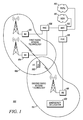
- FIG. 1 illustrates a simplified diagram of a mobile communication system according to a disclosed example.
- FIG. 2 illustrates a flow chart diagram of an emergency call placement method performed in a LE according to a disclosed example.
- FIG. 3 illustrates a message sequence chart showing an emergency call placement sequence according to the disclosed example.
- FIG. 4 illustrates a flow chart diagram of an emergency call placement method to perform the sequence illustrated in FIG. 3 .
- FIG. 5 illustrates a system diagram of user equipment according to a disclosed example.
- the present disclosure describes an emergency call placement method for user equipment (UE) where the UE detects initiation of an emergency call placed via a first radio access technology (e.g., via a WCDMA network or other suitable network) during an existing or non-idle connection mode. The UE then terminates the existing connection mode and initiates a new connection for the emergency call.
- This method allows the UE to issue an RRC connection request to a wireless communication network operating, for example, according to the 3GPP specification such that the network may initiate a redirection procedure that, in turn, effects establishment of the emergency call on a second radio access technology (e.g., a GSM network or other suitable network) to perform device location using UTDOA location method.
- a second radio access technology e.g., a GSM network or other suitable network
- FIG. 1 shows a simplified diagram of a mobile communication system 100 according to a disclosed example.
- a user equipment (UE) 102 communicates wirelessly with at least one base station (BS) operating according to a first radio access technology (RAT).
- RAT radio access technology
- the user equipment 102 communicates with a base station 104 operating according to a first radio access technology with geographic coverage diagrammatically illustrated by an area 106 .
- the first radio access technology is WCDMA pursuant to the 3G standard.
- Radio Access Technology can be considered to include not only the technology standards employed within a network, but also refers to physical characteristics (e.g., multiplexing technology, modulation schemes, channel bandwidth) through which different elements in the wireless network communicate.
- a radio network controller manages one or more base stations operating according to the first RAT.
- RNC 108 manages base station 104 and at least one other base station 110 .
- the radio network controller 108 and its associated base stations 104 and 110 make up the radio access network (RAN) operating according to a first radio access technology.
- RAN radio access network
- the radio access network may be, in turn, connected to a mobile switching center (MSC) 112 that allows connection to circuit switched networks, for example, such as a public switch telephone network (PSTN) 113 or an integrated services digital network (ISDN) 115 .
- MSC 112 for purposes of the disclosed example, is also connected to another radio network employing a second radio access technology such as GSM.
- GSM Global System for Mobile communications
- the user equipment 102 is also connectable to the second radio access technology (RAT), such as another network using a different radio access technology, indicated by area 114 .
- the second radio access network 114 includes one or more base stations 116 , only one of which is shown in FIG. 1 for illustrative purposes. This base station 116 and the other base stations (not shown) are connected to a radio network controller RNC 118 , which, in turn, connect to mobile switching center MSC 112 .
- the second radio access network employing the second radio access technology further includes an emergency UE locator 120 .
- this locator 120 is conceptually shown as a block within the second radio access technology area and may be implemented as either hardware, firmware or software in either a base station (e.g., base station 116 ), the radio network controller RNC 118 or some other device that implements the second radio access technology.
- the emergency UE locator 120 employs an Uplink Observed Time Difference of Arrival (UTDOA) for location of UEs in the GSM network.
- UTDOA Uplink Observed Time Difference of Arrival
- FIG. 2 illustrates a flow chart diagram 200 of an emergency call placement method performed in a UE according to a disclosed example.
- the method will be described in connection with the user equipment 102 shown in FIG. 1 , which is initially camped on base station 104 using WCDMA radio access technology. It will be recognized, however, that the method may be employed by any suitable device or system or subsystem or shared among multiple devices.
- an emergency call placement is started in UE 102 during an existing or non-idle connection mode.
- non-idle or existing connection mode refers to when the UE 102 is at least one of in a packet session, performing a location update or performing a routing area update.
- Emergency call placement occurs when a user presses 9-1-1 or an emergency button on the UE 102 .
- UE 102 then detects the emergency call request as shown in block 204 , and subsequently terminates the existing connection as shown in block 206 .
- the UE 102 initiates a new connection to the base station 104 for the emergency call with another radio resource control connection request in block 208 .
- the emergency call placement procedure ends as shown in block 210 .
- a network operator may have the capability of activating and deactivating the redirection feature for emergency calls based on a bit allocated in the non volatile memory of the UE 102 , which could be used to activate/deactivate this feature.
- the network operator desiring to use “emergency call redirection” may activate this feature by turning on this bit in the UE 102 , for example.
- decision block 212 in FIG. 2 which is interposed in the process between blocks 202 and 204 .
- flow no longer proceeds from block 202 to 204 , but rather from block 202 to block 212 .
- the UE 102 determines whether redirection has been activated within the device 102 . If not, then the procedure ends at block 210 . If, however, redirection has been activated, flow proceeds to block 204 where the method proceeds as discussed above.
- This procedure thereby allows the network using the first radio access technology network, namely a 3G network, to initiate procedures under the 3GPP specification to redirect the UE 102 to a second RAT technology for determining UE location.
- the entire procedure from initiation to end i.e., placement of the E911 call causing UE location determination) is illustrated in the message sequence chart of FIG. 3 .
- FIG. 3 shows a message sequence chart 300 showing an emergency call placement sequence according to a disclosed example.
- the UE is in a WCDMA radio resource control (RRC) connected mode to a base station, such as BS 104 , as indicated by reference number 302 .
- RRC radio resource control
- the user of the UE then initiates an emergency call.
- the UE terminates the WCDMA connected mode and temporarily moves to WCDMA idle mode.
- the UE then sends an RRC emergency connection request 304 to the network (e.g., through base station 104 as illustrated in FIG. 1 ).
- RRC radio resource control
- this request is made according to the 3GPP specification utilizing WCDMA.
- an RRC connection reject message 306 is sent to the UE in accordance with the 3GPP specification.
- the connection reject message includes redirection information concerning the presence of a second radio access technology (e.g., GSM).
- GSM second radio access technology
- This message includes, for example, an “Inter_RAT” information message according to the 3GPP specification directing the UE to search for suitable second radio access technology or “Inter_RAT” cell.
- the UE uses this information to initiate a connection to the suitable second radio access technology (RAT) that the UE finds.
- the UE initiates a redirection procedure to GSM radio access technology, as indicated by reference number 308 .
- the UE may measure the signal power of the GSM network and subsequently synchronize to a GSM cell from a current neighbor list, which is self-determined by the UE. This part of the procedure, however, may be omitted if the UE was already synchronized to cells from the neighbor list prior to redirection. Additionally, the UE may collect system information read from the GSM cell and select the most suitable second RAT (e.g., GSM) over which to establish an emergency call.
- GSM second RAT
- the UE then establishes the emergency call via the GSM radio access technology by issuing a channel request 310 indicating that the cause is an emergency call. Afterward, the call is successfully established between the UE and the network using GSM radio access technology as indicated by the arrow 312 . After the call has been successfully established, UE location determination is performed using location methods particular to the second radio access technology. In this example, the GSM network will utilize a signal time of arrival location method such as UTDOA as indicated by reference number 314 .
- UTDOA signal time of arrival location method
- FIG. 4 illustrates a flow chart diagram of an emergency call placement method to perform the sequence illustrated in FIG. 4 .
- This process may be executed by a processor in the UE 500 shown in FIG. 5 .
- a user initiates an emergency call as shown at input block 404 .
- This user initiation may be effected by inputting information to the processor 502 via a user interface 510 , as shown in FIG. 5 and discussed below.
- the process of FIG. 4 then proceeds to decision block 406 where a determination is made whether the UE is in an RRC connected mode to a first radio access technology. If the UE 500 is not in a connected mode, then the device may simply initiate an RRC connection request as shown in block 410 .
- the existing RRC connection is terminated and the UE 102 is placed into an idle mode as indicated in block 408 .
- the device then initiates a second or new RRC connection request as shown in block 410 .
- Flow proceeds to decision block 412 where the device waits to determine if an RRC connection rejection with “Inter_RAT” information is received.
- the rejection with “Inter_RAT” information i.e., redirection
- flow then proceeds to block 414 where the UE 102 initiates a redirection procedure to a second radio access technology as instructed by the RRC connection rejection with redirection. Included within this redirection procedure may be synchronization to the second radio access technology cell and collection of system information as was described previously with respect to FIG. 3 .
- a channel request is sent by the UE 500 utilizing the second radio access technology (e.g., GSM) for the emergency call.
- the network utilized by the second radio access technology responds, location determination is then employed by the network using the second radio access technology and the channel request signal received in block 416 to locate the UE 500 in response to the emergency call as indicated in block 418 .
- the UE reciprocates and establishes a call as indicated in block 419 . Once a call is established, the procedure ends as indicated at block 420 .
- FIG. 5 illustrates a system diagram of user equipment according to a disclosed example, such as user equipment 102 shown in FIG. 1 .
- a user equipment 500 includes a processor 502 that is configured to execute the emergency call procedure of the present disclosure, which instructions may be stored in a storage medium such as memory 504 .
- the processor 502 and memory 504 may be integral or separate and that the emergency call procedure of the present disclosure may be implemented as software, firmware, or dedicated hardware within the processor 502 , or in any suitable manner.
- the UE 500 also includes first and second wireless transceivers 506 and 507 connected to respective antennas 508 and 509 , the first transceiver 506 being configured to operate according a first radio access technology and the second transceiver being configured to operate according to a second radio access technology.
- the first and second transceivers 506 , 507 may be housed or combined as a single transceiver 512 as shown in FIG. 5 configured to utilize a plurality of radio access technologies.
- the UE 500 also includes a user interface 510 allowing a user to input information, such as the initiation of an emergency call.
- the user interface may include a display by which the processor 502 may display information to a user.
- the user interface 510 may also include a keypad, microphone, loudspeaker, and a panic or emergency button, as examples.
- the UE 500 may also include an emergency call controller 514 containing dedicated software for performing the previously described procedure of FIGS. 2-4 that can be implemented as software in the memory 504 or the processor 502 , or also implementable with hardware or firmware.
- the illustrated components of UE 500 perform the emergency call procedure disclosed.
- user interface 510 is configured to receive input information from the user, such as input of an emergency call, and supply the input information to the processor 502 .
- the processor 502 is then configured to recognize the emergency call input.
- the transceiver 506 is configured to recognize an emergency call input while it is in an existing connection mode using a first radio access technology.
- the processor then initiates termination of the existing connection mode of the transceiver 506 and causes the UE 500 to enter the first RAT idle mode. After entering the idle mode, the processor 502 signals the transceiver 506 to issue a connection request to the first radio access technology network including information indicating that the cause of the connection request is an emergency call.
- the processor 502 is also further configured to recognize the RRC connection rejection from the first RAT network received via the transceiver 506 and initiate a redirection procedure such as the redirection procedure mandated by the 3GPP specification. The processor 502 then will signal the second transceiver 507 to establish a channel request for a new connection using a second radio access technology in which the transceiver 507 is designed to operate.
- the disclosed methods and apparatus provide an emergency call placement methodology that allows a user equipment operating in an existing connection mode particularly in 3G systems to avoid the scenario where the 3G network cannot redirect the UE to another radio access technology to perform a location determination for emergency calls. This is accomplished by providing a UE apparatus and method that terminate the existing call and initiate a new connection request such that the network will respond according to the prescribed protocol under the 3GPP specification.
Abstract
Description
Claims (18)
Priority Applications (6)
| Application Number | Priority Date | Filing Date | Title |
|---|---|---|---|
| US11/004,520 US8855596B2 (en) | 2004-12-03 | 2004-12-03 | Methods and apparatus for placement of an emergency call |
| PCT/US2005/039721 WO2006062632A2 (en) | 2004-12-03 | 2005-11-03 | Methods and apparatus for placement of an emergency call |
| CNA2005800400179A CN101061740A (en) | 2004-12-03 | 2005-11-03 | Methods and apparatus for placement of an emergency call |
| KR1020077012596A KR20070085732A (en) | 2004-12-03 | 2005-11-03 | Methods and apparatus for placement of an emergency call |
| RU2007125127/09A RU2389157C2 (en) | 2004-12-03 | 2005-11-03 | Methods and device for making emergency call |
| EP05825012A EP1820367A2 (en) | 2004-12-03 | 2005-11-03 | Methods and apparatus for placement of an emergency call |
Applications Claiming Priority (1)
| Application Number | Priority Date | Filing Date | Title |
|---|---|---|---|
| US11/004,520 US8855596B2 (en) | 2004-12-03 | 2004-12-03 | Methods and apparatus for placement of an emergency call |
Publications (2)
| Publication Number | Publication Date |
|---|---|
| US20060121877A1 US20060121877A1 (en) | 2006-06-08 |
| US8855596B2 true US8855596B2 (en) | 2014-10-07 |
Family
ID=36574975
Family Applications (1)
| Application Number | Title | Priority Date | Filing Date |
|---|---|---|---|
| US11/004,520 Active 2027-04-06 US8855596B2 (en) | 2004-12-03 | 2004-12-03 | Methods and apparatus for placement of an emergency call |
Country Status (6)
| Country | Link |
|---|---|
| US (1) | US8855596B2 (en) |
| EP (1) | EP1820367A2 (en) |
| KR (1) | KR20070085732A (en) |
| CN (1) | CN101061740A (en) |
| RU (1) | RU2389157C2 (en) |
| WO (1) | WO2006062632A2 (en) |
Families Citing this family (20)
| Publication number | Priority date | Publication date | Assignee | Title |
|---|---|---|---|---|
| DE10101282A1 (en) * | 2001-01-12 | 2002-07-18 | Siemens Ag | Emergency call notification using mobile telecommunication devices |
| GB2463230A (en) * | 2008-08-28 | 2010-03-10 | Nec Corp | Provision of emergency call service in a cellular communication system |
| US20110261726A1 (en) * | 2008-11-07 | 2011-10-27 | Hannu Tapio Hakkinen | Emergency Call in Radio System |
| JP5205236B2 (en) * | 2008-12-04 | 2013-06-05 | 株式会社エヌ・ティ・ティ・ドコモ | Mobile communication method, mobile station, and network device |
| WO2011083151A1 (en) * | 2010-01-08 | 2011-07-14 | Research In Motion Limited | Emergency radio connection setup |
| US8483058B2 (en) * | 2010-08-17 | 2013-07-09 | Qualcomm Incorporated | Systems and methods for traffic policing |
| CN103238368B (en) | 2010-12-03 | 2017-02-15 | 交互数字专利控股公司 | Method, apparatus and system for performing multi-radio access technology carrier aggregation |
| US8995370B2 (en) | 2011-07-29 | 2015-03-31 | Interdigital Patent Holdings, Inc. | Method and apparatus for radio resources management in multi-radio access technology wireless systems |
| KR20130020252A (en) * | 2011-08-19 | 2013-02-27 | 삼성전자주식회사 | Apparatus and method for transmitting an emergency call in a portable terminal |
| GB2489545B (en) * | 2011-11-29 | 2013-05-29 | Renesas Mobile Corp | Method, apparatus and computer program for establishing an emergency service |
| KR102011268B1 (en) * | 2012-11-02 | 2019-08-16 | 삼성전자주식회사 | Radio access technology searching method for emergency call of wireless terminal supporting multiple communication network, and apparatus thereof |
| GB2523335B (en) * | 2014-02-20 | 2018-02-14 | Ip Access Ltd | Network elements, wireless communication system and methods therefor |
| US20150257013A1 (en) * | 2014-03-04 | 2015-09-10 | Qualcomm Incorporated | Inter-radio access technology advertising in a multi-radio access technology deployment |
| CN107360558A (en) * | 2017-06-19 | 2017-11-17 | 努比亚技术有限公司 | Emergency call control method, communication terminal and computer-readable recording medium |
| US10816635B1 (en) | 2018-12-20 | 2020-10-27 | Autonomous Roadway Intelligence, Llc | Autonomous vehicle localization system |
| US10814474B2 (en) | 2018-12-20 | 2020-10-27 | Autonomous Roadway Intelligence, Llc | Identification and localization of mobile robots |
| US10820349B2 (en) | 2018-12-20 | 2020-10-27 | Autonomous Roadway Intelligence, Llc | Wireless message collision avoidance with high throughput |
| US10713950B1 (en) | 2019-06-13 | 2020-07-14 | Autonomous Roadway Intelligence, Llc | Rapid wireless communication for vehicle collision mitigation |
| US10939471B2 (en) | 2019-06-13 | 2021-03-02 | David E. Newman | Managed transmission of wireless DAT messages |
| US10820182B1 (en) | 2019-06-13 | 2020-10-27 | David E. Newman | Wireless protocols for emergency message transmission |
Citations (10)
| Publication number | Priority date | Publication date | Assignee | Title |
|---|---|---|---|---|
| WO1998046035A2 (en) | 1997-04-10 | 1998-10-15 | Qualcomm Incorporated | Determining the location of a subscriber unit in a mobile communication system |
| US6115599A (en) * | 1999-01-08 | 2000-09-05 | Trueposition, Inc. | Directed retry method for use in a wireless location system |
| US20030096614A1 (en) * | 2001-11-19 | 2003-05-22 | Toni Paila | Method and system of identifying network services |
| US20030114158A1 (en) * | 2001-12-18 | 2003-06-19 | Lauri Soderbacka | Intersystem handover of a mobile terminal |
| WO2003096727A1 (en) | 2002-05-13 | 2003-11-20 | Qualcomm, Incorporated | Subscriber station with dynamic multi-mode service acquisition capability |
| US6697630B1 (en) | 2000-03-17 | 2004-02-24 | Lucent Technologies, Inc. | Automatic location identification system comparing stored field strength data and an actual cellular call's field strength |
| US20040242191A1 (en) * | 2003-01-21 | 2004-12-02 | Asif Hossain | Method and apparatus for a mobile station to enhance the probability of successful emergency call completion and successful callback from emergency service centre |
| WO2005004526A1 (en) * | 2003-07-04 | 2005-01-13 | Telefonaktiebolaget Lm Ericsson (Publ) | Indicating availability status of services provided by a mobile communication network |
| US7031725B2 (en) * | 2002-08-13 | 2006-04-18 | Drs Communications Company, Llc | Method and system for determining relative positions of networked mobile communication devices |
| US20060153342A1 (en) * | 2005-01-07 | 2006-07-13 | Oki Electric Industry Co., Ltd. | Emergency call system |
-
2004
- 2004-12-03 US US11/004,520 patent/US8855596B2/en active Active
-
2005
- 2005-11-03 CN CNA2005800400179A patent/CN101061740A/en active Pending
- 2005-11-03 KR KR1020077012596A patent/KR20070085732A/en not_active Application Discontinuation
- 2005-11-03 EP EP05825012A patent/EP1820367A2/en not_active Ceased
- 2005-11-03 WO PCT/US2005/039721 patent/WO2006062632A2/en active Application Filing
- 2005-11-03 RU RU2007125127/09A patent/RU2389157C2/en active
Patent Citations (11)
| Publication number | Priority date | Publication date | Assignee | Title |
|---|---|---|---|---|
| WO1998046035A2 (en) | 1997-04-10 | 1998-10-15 | Qualcomm Incorporated | Determining the location of a subscriber unit in a mobile communication system |
| US6115599A (en) * | 1999-01-08 | 2000-09-05 | Trueposition, Inc. | Directed retry method for use in a wireless location system |
| US6697630B1 (en) | 2000-03-17 | 2004-02-24 | Lucent Technologies, Inc. | Automatic location identification system comparing stored field strength data and an actual cellular call's field strength |
| US20030096614A1 (en) * | 2001-11-19 | 2003-05-22 | Toni Paila | Method and system of identifying network services |
| US20030114158A1 (en) * | 2001-12-18 | 2003-06-19 | Lauri Soderbacka | Intersystem handover of a mobile terminal |
| WO2003096727A1 (en) | 2002-05-13 | 2003-11-20 | Qualcomm, Incorporated | Subscriber station with dynamic multi-mode service acquisition capability |
| US7031725B2 (en) * | 2002-08-13 | 2006-04-18 | Drs Communications Company, Llc | Method and system for determining relative positions of networked mobile communication devices |
| US20040242191A1 (en) * | 2003-01-21 | 2004-12-02 | Asif Hossain | Method and apparatus for a mobile station to enhance the probability of successful emergency call completion and successful callback from emergency service centre |
| WO2005004526A1 (en) * | 2003-07-04 | 2005-01-13 | Telefonaktiebolaget Lm Ericsson (Publ) | Indicating availability status of services provided by a mobile communication network |
| US20060209675A1 (en) * | 2003-07-04 | 2006-09-21 | Caroline Jacobson | Indicating availabiliy status of services provided by a mobile communication network |
| US20060153342A1 (en) * | 2005-01-07 | 2006-07-13 | Oki Electric Industry Co., Ltd. | Emergency call system |
Non-Patent Citations (5)
| Title |
|---|
| Chinese Office Action; Chines Application No. 200580040017.9; dated Sep. 4, 2009. |
| EP Office Action; EP Application No. 05825012.7; dated Oct. 16, 2007. |
| EP Oral Proceedings Summons; EP Application No. 05825012.7; dated Dec. 10, 2009. |
| International Search Report dated Jun. 12, 2006 for International Application No. PCT/US2005/039721, p. 1. |
| Russian Decision on Grant; Russian Application No. 2007125127/09; dated Nov. 23, 2009. |
Also Published As
| Publication number | Publication date |
|---|---|
| US20060121877A1 (en) | 2006-06-08 |
| CN101061740A (en) | 2007-10-24 |
| WO2006062632B1 (en) | 2006-09-14 |
| WO2006062632A2 (en) | 2006-06-15 |
| WO2006062632A3 (en) | 2006-08-10 |
| KR20070085732A (en) | 2007-08-27 |
| RU2007125127A (en) | 2009-01-10 |
| RU2389157C2 (en) | 2010-05-10 |
| EP1820367A2 (en) | 2007-08-22 |
Similar Documents
| Publication | Publication Date | Title |
|---|---|---|
| RU2389157C2 (en) | Methods and device for making emergency call | |
| EP1935205B1 (en) | User terminal-initiated hard handoff from a wireless local area network to a cellular network | |
| US6456858B1 (en) | System and methods in a dual mode wireless system for transmitting rescan command based on detected network conditions | |
| EP1590928B1 (en) | Hybrid protocol to support communications with multiple networks | |
| KR100995785B1 (en) | Hard handoff from a wireless local area network to a cellular telephone network | |
| KR100557119B1 (en) | Method for controlling operation mode of hybrid mobile terminal supporting voice service and packet data service | |
| US7079841B2 (en) | Apparatus for performing a handover between different mobile communication systems and method for controlling the same | |
| US20060160544A1 (en) | Distance dependent direct mode peer -to-peer communication establishment in a tdd cdma network | |
| EP2014121B1 (en) | A method of operation in a dual carrier communication system | |
| US9370039B2 (en) | Radio base station and method | |
| US20090034469A1 (en) | Method and system for searching target cell by using multimode-multiband terminal in mobile communication environment | |
| US20090275360A1 (en) | Hybrid mobile communication terminal and method of acquiring system for data service in hybrid mobile communication terminal | |
| EP2272299A1 (en) | Connection establishment system and method | |
| GB2288301A (en) | Methods and apparatus for call handover between different mobile radio networks | |
| CN101543130A (en) | Selecting an access method while performing handovers in a mobile communication system | |
| EP1250823B1 (en) | Hybrid cellular network system and communications method | |
| JPH08502637A (en) | Method to reduce audio gap in downlink during cellular radiotelephone handoff | |
| JP4433152B2 (en) | Method of handover in a multi-mode telecommunications network | |
| KR101221235B1 (en) | Efficient sharing of mobile equipment identifiers | |
| EP2437543A1 (en) | Local circuit switched fallback cancellation mechanism | |
| US7421280B2 (en) | Wireless network and wireless access terminals using enhanced SYNC—ID parameter | |
| KR100886310B1 (en) | System and method for enhanced over-the-air programming | |
| US6879580B1 (en) | Combined CDMA multi-service carrier and TDMA/CDMA packet carrier | |
| EP3182763B1 (en) | Method and apparatus for network access | |
| GB2321165A (en) | Methods and apparatus for call handover between different mobile radio networks |
Legal Events
| Date | Code | Title | Description |
|---|---|---|---|
| AS | Assignment |
Owner name: MOTOROLA, INC., ILLINOIS Free format text: ASSIGNMENT OF ASSIGNORS INTEREST;ASSIGNORS:RAGHURAM, SHARADA;DORSEY, DONALD A.;POLISETTY, ROHINI;REEL/FRAME:016051/0591 Effective date: 20041202 |
|
| AS | Assignment |
Owner name: MOTOROLA MOBILITY, INC, ILLINOIS Free format text: ASSIGNMENT OF ASSIGNORS INTEREST;ASSIGNOR:MOTOROLA, INC;REEL/FRAME:025673/0558 Effective date: 20100731 |
|
| AS | Assignment |
Owner name: MOTOROLA MOBILITY LLC, ILLINOIS Free format text: ASSIGNMENT OF ASSIGNORS INTEREST;ASSIGNOR:MOTOROLA MOBILITY, INC.;REEL/FRAME:028829/0856 Effective date: 20120622 |
|
| STCF | Information on status: patent grant |
Free format text: PATENTED CASE |
|
| AS | Assignment |
Owner name: GOOGLE TECHNOLOGY HOLDINGS LLC, CALIFORNIA Free format text: ASSIGNMENT OF ASSIGNORS INTEREST;ASSIGNOR:MOTOROLA MOBILITY LLC;REEL/FRAME:034227/0095 Effective date: 20141028 |
|
| AS | Assignment |
Owner name: GOOGLE TECHNOLOGY HOLDINGS LLC, CALIFORNIA Free format text: ASSIGNMENT OF ASSIGNORS INTEREST;ASSIGNOR:MOTOROLA MOBILITY LLC;REEL/FRAME:034275/0004 Effective date: 20141028 |
|
| MAFP | Maintenance fee payment |
Free format text: PAYMENT OF MAINTENANCE FEE, 4TH YEAR, LARGE ENTITY (ORIGINAL EVENT CODE: M1551) Year of fee payment: 4 |
|
| MAFP | Maintenance fee payment |
Free format text: PAYMENT OF MAINTENANCE FEE, 8TH YEAR, LARGE ENTITY (ORIGINAL EVENT CODE: M1552); ENTITY STATUS OF PATENT OWNER: LARGE ENTITY Year of fee payment: 8 |