US8832915B2 - Apparatus and method for the connection of conduits - Google Patents
Apparatus and method for the connection of conduits Download PDFInfo
- Publication number
- US8832915B2 US8832915B2 US13/262,615 US201013262615A US8832915B2 US 8832915 B2 US8832915 B2 US 8832915B2 US 201013262615 A US201013262615 A US 201013262615A US 8832915 B2 US8832915 B2 US 8832915B2
- Authority
- US
- United States
- Prior art keywords
- conduit
- guide
- carrier
- clamp
- guide arms
- Prior art date
- Legal status (The legal status is an assumption and is not a legal conclusion. Google has not performed a legal analysis and makes no representation as to the accuracy of the status listed.)
- Active, expires
Links
Images


Classifications
-
- F—MECHANICAL ENGINEERING; LIGHTING; HEATING; WEAPONS; BLASTING
- F16—ENGINEERING ELEMENTS AND UNITS; GENERAL MEASURES FOR PRODUCING AND MAINTAINING EFFECTIVE FUNCTIONING OF MACHINES OR INSTALLATIONS; THERMAL INSULATION IN GENERAL
- F16L—PIPES; JOINTS OR FITTINGS FOR PIPES; SUPPORTS FOR PIPES, CABLES OR PROTECTIVE TUBING; MEANS FOR THERMAL INSULATION IN GENERAL
- F16L1/00—Laying or reclaiming pipes; Repairing or joining pipes on or under water
- F16L1/26—Repairing or joining pipes on or under water
-
- E—FIXED CONSTRUCTIONS
- E21—EARTH DRILLING; MINING
- E21B—EARTH DRILLING, e.g. DEEP DRILLING; OBTAINING OIL, GAS, WATER, SOLUBLE OR MELTABLE MATERIALS OR A SLURRY OF MINERALS FROM WELLS
- E21B41/00—Equipment or details not covered by groups E21B15/00 - E21B40/00
- E21B41/04—Manipulators for underwater operations, e.g. temporarily connected to well heads
-
- E—FIXED CONSTRUCTIONS
- E21—EARTH DRILLING; MINING
- E21B—EARTH DRILLING, e.g. DEEP DRILLING; OBTAINING OIL, GAS, WATER, SOLUBLE OR MELTABLE MATERIALS OR A SLURRY OF MINERALS FROM WELLS
- E21B43/00—Methods or apparatus for obtaining oil, gas, water, soluble or meltable materials or a slurry of minerals from wells
- E21B43/01—Methods or apparatus for obtaining oil, gas, water, soluble or meltable materials or a slurry of minerals from wells specially adapted for obtaining from underwater installations
- E21B43/013—Connecting a production flow line to an underwater well head
-
- F—MECHANICAL ENGINEERING; LIGHTING; HEATING; WEAPONS; BLASTING
- F16—ENGINEERING ELEMENTS AND UNITS; GENERAL MEASURES FOR PRODUCING AND MAINTAINING EFFECTIVE FUNCTIONING OF MACHINES OR INSTALLATIONS; THERMAL INSULATION IN GENERAL
- F16L—PIPES; JOINTS OR FITTINGS FOR PIPES; SUPPORTS FOR PIPES, CABLES OR PROTECTIVE TUBING; MEANS FOR THERMAL INSULATION IN GENERAL
- F16L21/00—Joints with sleeve or socket
- F16L21/06—Joints with sleeve or socket with a divided sleeve or ring clamping around the pipe-ends
- F16L21/065—Joints with sleeve or socket with a divided sleeve or ring clamping around the pipe-ends tightened by tangentially-arranged threaded pins
-
- F—MECHANICAL ENGINEERING; LIGHTING; HEATING; WEAPONS; BLASTING
- F16—ENGINEERING ELEMENTS AND UNITS; GENERAL MEASURES FOR PRODUCING AND MAINTAINING EFFECTIVE FUNCTIONING OF MACHINES OR INSTALLATIONS; THERMAL INSULATION IN GENERAL
- F16L—PIPES; JOINTS OR FITTINGS FOR PIPES; SUPPORTS FOR PIPES, CABLES OR PROTECTIVE TUBING; MEANS FOR THERMAL INSULATION IN GENERAL
- F16L23/00—Flanged joints
- F16L23/04—Flanged joints the flanges being connected by members tensioned in the radial plane
- F16L23/08—Flanged joints the flanges being connected by members tensioned in the radial plane connection by tangentially arranged pin and nut
-
- F—MECHANICAL ENGINEERING; LIGHTING; HEATING; WEAPONS; BLASTING
- F16—ENGINEERING ELEMENTS AND UNITS; GENERAL MEASURES FOR PRODUCING AND MAINTAINING EFFECTIVE FUNCTIONING OF MACHINES OR INSTALLATIONS; THERMAL INSULATION IN GENERAL
- F16L—PIPES; JOINTS OR FITTINGS FOR PIPES; SUPPORTS FOR PIPES, CABLES OR PROTECTIVE TUBING; MEANS FOR THERMAL INSULATION IN GENERAL
- F16L37/00—Couplings of the quick-acting type
- F16L37/002—Couplings of the quick-acting type which can be controlled at a distance
-
- Y—GENERAL TAGGING OF NEW TECHNOLOGICAL DEVELOPMENTS; GENERAL TAGGING OF CROSS-SECTIONAL TECHNOLOGIES SPANNING OVER SEVERAL SECTIONS OF THE IPC; TECHNICAL SUBJECTS COVERED BY FORMER USPC CROSS-REFERENCE ART COLLECTIONS [XRACs] AND DIGESTS
- Y10—TECHNICAL SUBJECTS COVERED BY FORMER USPC
- Y10T—TECHNICAL SUBJECTS COVERED BY FORMER US CLASSIFICATION
- Y10T29/00—Metal working
- Y10T29/49—Method of mechanical manufacture
- Y10T29/49826—Assembling or joining
- Y10T29/49895—Associating parts by use of aligning means [e.g., use of a drift pin or a "fixture"]
- Y10T29/49899—Associating parts by use of aligning means [e.g., use of a drift pin or a "fixture"] by multiple cooperating aligning means
-
- Y—GENERAL TAGGING OF NEW TECHNOLOGICAL DEVELOPMENTS; GENERAL TAGGING OF CROSS-SECTIONAL TECHNOLOGIES SPANNING OVER SEVERAL SECTIONS OF THE IPC; TECHNICAL SUBJECTS COVERED BY FORMER USPC CROSS-REFERENCE ART COLLECTIONS [XRACs] AND DIGESTS
- Y10—TECHNICAL SUBJECTS COVERED BY FORMER USPC
- Y10T—TECHNICAL SUBJECTS COVERED BY FORMER US CLASSIFICATION
- Y10T29/00—Metal working
- Y10T29/49—Method of mechanical manufacture
- Y10T29/49826—Assembling or joining
- Y10T29/49895—Associating parts by use of aligning means [e.g., use of a drift pin or a "fixture"]
- Y10T29/49902—Associating parts by use of aligning means [e.g., use of a drift pin or a "fixture"] by manipulating aligning means
-
- Y—GENERAL TAGGING OF NEW TECHNOLOGICAL DEVELOPMENTS; GENERAL TAGGING OF CROSS-SECTIONAL TECHNOLOGIES SPANNING OVER SEVERAL SECTIONS OF THE IPC; TECHNICAL SUBJECTS COVERED BY FORMER USPC CROSS-REFERENCE ART COLLECTIONS [XRACs] AND DIGESTS
- Y10—TECHNICAL SUBJECTS COVERED BY FORMER USPC
- Y10T—TECHNICAL SUBJECTS COVERED BY FORMER US CLASSIFICATION
- Y10T29/00—Metal working
- Y10T29/49—Method of mechanical manufacture
- Y10T29/49826—Assembling or joining
- Y10T29/49947—Assembling or joining by applying separate fastener
- Y10T29/49948—Multipart cooperating fastener [e.g., bolt and nut]
-
- Y—GENERAL TAGGING OF NEW TECHNOLOGICAL DEVELOPMENTS; GENERAL TAGGING OF CROSS-SECTIONAL TECHNOLOGIES SPANNING OVER SEVERAL SECTIONS OF THE IPC; TECHNICAL SUBJECTS COVERED BY FORMER USPC CROSS-REFERENCE ART COLLECTIONS [XRACs] AND DIGESTS
- Y10—TECHNICAL SUBJECTS COVERED BY FORMER USPC
- Y10T—TECHNICAL SUBJECTS COVERED BY FORMER US CLASSIFICATION
- Y10T29/00—Metal working
- Y10T29/53—Means to assemble or disassemble
- Y10T29/5367—Coupling to conduit
-
- Y—GENERAL TAGGING OF NEW TECHNOLOGICAL DEVELOPMENTS; GENERAL TAGGING OF CROSS-SECTIONAL TECHNOLOGIES SPANNING OVER SEVERAL SECTIONS OF THE IPC; TECHNICAL SUBJECTS COVERED BY FORMER USPC CROSS-REFERENCE ART COLLECTIONS [XRACs] AND DIGESTS
- Y10—TECHNICAL SUBJECTS COVERED BY FORMER USPC
- Y10T—TECHNICAL SUBJECTS COVERED BY FORMER US CLASSIFICATION
- Y10T29/00—Metal working
- Y10T29/53—Means to assemble or disassemble
- Y10T29/53961—Means to assemble or disassemble with work-holder for assembly
Definitions
- This invention relates to apparatus and methods for aligning conduits for connection together.
- conduits such as those used in the oil and gas industry.
- FIG. 1 shows a typical riser tower subsea installation featuring a number of situations where connections need to be made between conduits.
- a riser tower 10 is moored to the seabed 12 and connected to a surface production platform 14 such as a FPSO.
- Typical connections points that can be present in such an assembly exist between jumpers 16 that run from the riser tower 10 to flow line termination assemblies 18 (FTA), between FTAs 18 and pipelines 20 on the seabed 12 and between pipelines connecting production manifolds 22 and subsea trees 24 at the start of subsea oil well.
- FTA flow line termination assemblies
- the conduits may be pipelines or cables for containing fluids, e.g. liquid or gas, and/or may contain electrical, hydraulic and/or optical services to be connected. Connections may be joining one length of a conduit to another, i.e. a midline connection, or connections may be at the start or finish point of the conduit, i.e. a termination connection, to another apparatus.
- FIG. 2 shows the connection of a first conduit 26 with a second conduit 28 having a seal 30 between the end faces of the conduits and a closure mechanism 32 , such as a clamp, around the hub of the connection.
- a closure mechanism 32 such as a clamp
- the conduits In order for a satisfactory connection to be achieved the conduits must be sufficiently aligned for the liquid, gas, electricity, light etc to pass across the interface.
- the accuracy that needs to be achieved with the alignment can depend on the nature of the conduit and the nature of the contents of the conduits (liquid, gas, electricity, light etc). Typically the accuracy required will be specified in millimeters. Alignment is generally achieved through a series of steps carried out by a connection tool each step providing more accurate alignment until the final stage brings the conduits together with the accuracy required for the content of the conduit to pass across the interface and still remain contained within the conduit.
- the conduits must also be bought into contact with each other with sufficient force and intimacy to ensure whatever seals or devices required to contain the contents of the conduits are retained and/or activated.
- conduits must then be able to be securely retained in the closed position by a closure device that resists both internal and external forces that the connection may be subjected to throughout its service life.
- EP1956184 and US20010010782 describe methods and apparatus for aligning and connecting conduits.
- This invention provides an apparatus for connecting adjacent ends of first and second conduits comprising:
- the guide can comprise a pair of side members, defining a space therebetween for receiving the end of the second conduit, the first and second guide formations being provided in each side member.
- the side members can include channels within which the carrier slides so as to move between the first and second positions, the guide formations in each side member opening into the respective channel
- the slots in the carrier locate the guide arms such that the end of the second conduit is positioned co axially with the end of the first conduit fixed to the frame.
- the guide formations can include retaining mechanisms to prevent accidental disengagement of the guide arms during use.
- the apparatus can comprise a drive mechanism that is fixed to the frame and connects to the carrier and is operable to move the carrier between the first and second positions.
- the driving mechanism can be detachable from the carrier.
- the apparatus may comprise a closure mechanism connected to the frame and operable to form the connection to secure the ends of the conduits together when the end of the second conduit is in the second position.
- the closure mechanism can comprise a clamping assembly including a plurality of clamp segments and an actuating mechanism operable to force the clamp segments into engagement with formations on the ends of the conduits to secure the ends together.
- the apparatus can comprise a pair of clamp segments and a pair of actuators extending between the clamp segments on either side of the connection.
- the closure mechanism comprises clamp segments mounted on a mounting member by means of hinges and connected to each other by an actuator.
- the closure mechanism comprises clamp segments connected by a flexible band that can pass around the ends of the conduits, the band having a lug at each end and an actuator extending between the lugs.
- a second aspect of the invention comprises a clamp for connecting a first conduit to a second conduit comprising;
- the clamp can comprise a removeable cartridge for housing the actuator.
- a third aspect of the invention comprises a method of connecting the ends of first and second conduits using an apparatus as described above, the method comprising:
- the method can further comprise securing the ends of the conduit together with a clamp as described above.
- a fourth aspect of the invention comprises a method of deploying a second conduit from a vessel for connecting to a first conduit comprising:
- the method to connect the second conduit to the first conduit can comprise:
- FIG. 1 shows a typical riser tower subsea installation comprising connections between conduits
- FIG. 2 shows a typical connection between two conduits
- FIG. 3 shows a schematic diagram of the connection tool according to the invention
- FIG. 4 shows a connection tool being used to connect one conduit to another in a subsea environment
- FIG. 5 shows a connection tool being used to connect one conduit to another in the surface environment
- FIGS. 6-8 shows further alignment mechanism which can be used in combination with the connection tool of the invention
- FIGS. 9-16 shows different orientations that the connection tool can be used to connect two conduits
- FIG. 17 shows a clamp structure for which the invention can be used in combination with
- FIG. 18 shows an expanded view of a clamp for closure of the conduit connection
- FIG. 19 shows a cross sectional view of a clamp for closure of the conduit connection
- FIG. 20 shows an expanded view of a segment clamp for closure of a conduit connection
- FIG. 21 shows a schematic diagram of segmented clamp in a closed position according to the invention.
- FIG. 22 shows a schematic diagram of a segmented claim in an open position according to the invention.
- FIG. 3 shows a connection tool 40 according to the invention for aligning and connecting a first conduit 42 to a second conduit 44 .
- the connection tool 40 comprises a frame assembly 46 in which a fixed first conduit 42 already installed is attached.
- the frame assembly 46 comprises a guide 48 , or alignment block, comprising a pair of side members and first 50 and second 52 pairs of guide formations.
- the guide formations 50 , 52 are connected to a channel running along the length of the side members of the guide and are configured to receive guide arms 60 , 62 of the second conduit.
- a carrier or slider 54 in which the second conduit 44 to be connected to the fixed conduit 42 is mounted, is slidably attached to the guide 48 and the frame assembly 46 .
- the carrier 54 is positioned between a space defined by the side members of the guide 48 with longitudinal side walls of the carrier being located in the channels.
- the carrier is moveable between two positions. When the carrier is in the first position slots in the side walls of the carrier align with the guide formations and can receive the guide arms from the guide formations.
- the carrier is connected to a driving mechanism, such as rams 56 aligned parallel to the longitudinal axis of the fixed conduit 42 to move the carrier to its second position where the end of the second conduit is held against the end of the first conduit.
- the rams 56 are actuable to move the carrier 54 along the frame assembly 46 and channel to bring the end of the second conduit 44 into contact with the first conduit 42 .
- the end portion of the second conduit 44 to be connected to the fixed conduit 42 comprises an alignment head 58 having first 60 and second 62 pairs of guide arms extending radially out from the conduit 44 .
- the guide arms 60 , 62 are engagable with the guide formations 50 , 52 on the guide 48 of the frame assembly 46 .
- a first conduit 42 is assembled in the connection tool 40 , such that it is in a fixed stationary position.
- the second conduit 44 is bought towards the connection tool, to be placed in the tool.
- the initial alignment can be provided by a ROV 64 .
- the ROV 64 guides the second conduit 44 to the connection tool 40 and provides manual intervention and guidance to the vessel watch keeper to guide the alignment head 58 of the conduit 44 into the guide 48 of the connection tool 40 .
- a crane 66 can carry the second conduit 44 to the connection tool.
- the initial alignment can be provided by a person providing manual intervention through tag lines 66 and verbal guidance to the crane operator to guide the alignment head 58 of the conduit 44 into the guide member of the 48 of the connection tool 40 , as shown in FIG. 5 .
- the initial contact between the second conduit 44 and connection tool 40 does not require accurate alignment and a rudimentary alignment to place the second conduit 44 into the connection tool 40 will suffice.
- the second conduit 44 is moved so that the first guide arms 60 are located in the first guide formations 50 .
- the second pair of guide arms 62 can be moved in the second guide formations 52 .
- FIG. 3 shows the second conduit being installed from a vertical position into a final horizontal position. In this situation once the first guide arms 60 are engaged in the formations 50 , the second conduit pivots about a point around the axis of the first guide arms and as the second conduit is lowered the second guide arms 62 are positioned into the second guide formations 52 .
- the carrier 54 moves towards the fixed conduit 42 the carrier is kept in position by the sides of the carrier moving along channels in the sides of the guide 48 .
- the guide arms 50 , 52 extending into slots in the side of the carrier 54 at least a portion of the guide arms 50 , 52 are also located in the channel of the guide. This helps place the central axis of the interface of the conduit 44 being installed within a sufficient tolerance, typically ⁇ 5 mm, of the centre axis of the interface of the fixed conduit 42 .
- FIGS. 6-8 exemplifies some possible fine alignment mechanisms compatible with the present invention.
- the conduits 42 , 44 being installed can comprise complementary male 70 and female 72 tapered end faces to enable a close fit with each other.
- one conduit 44 can comprise a docking member 74 extending from its end face, with the other conduit 42 having a complementary aperture 76 into which the docking member 74 is inserted as the second conduit 44 is brought together with the fixed conduit 42 .
- the fine alignment mechanism is separate from the interface of the conduits.
- a docking member 78 extends forward from the alignment head 58 of the conduit 44 to be installed, while a complementary locating aperture 80 is attached to the fixed conduit 42 .
- the docking member 78 is inserted into the aperture 80 as the faces of the conduits are bought closer together.
- the fine alignment mechanism is separate from the interface of the conduits.
- Other suitable fine alignment mechanism can also be used with the connection tool.
- FIGS. 9-16 shows examples of orientation where the connection tool can be used.
- the connection tool 40 can be used in a horizontal position where the second conduit 44 is being installed from a vertical position.
- FIGS. 11 and 12 show the connection tool 40 used in a horizontal position wherein the second conduit 44 is being installed from a horizontal position.
- the connection tool 40 can be used in a vertical position with vertical insertion of the second conduit 44 to vertically positioned first conduit 42 as shown in FIGS. 13 and 14 .
- the connection can also be used in an upside down horizontal position, as shown in FIGS. 15 and 16 , such that the second conduit 44 is raised to be inserted into the connection tool 40 having a horizontally aligned first conduit 42 connected.
- connection tool 40 can further comprise a retaining mechanism or latch mechanism (not shown) to retain the first pair of guide arms 60 in the first pair of guide formations 50 .
- the retaining mechanism can prevent accidental disengagement of the guide arms during use.
- connection tool is applicable for the alignment of any conduit
- the tool is particularly suitable for use with conduits of a size and/or stiffness such that the loads required to achieve alignment are very high.
- conduits of a size and/or stiffness such that the loads required to achieve alignment are very high.
- these include large diameter pipelines used either subsea or on land, for the transmission of oil or gas, or for conduits with thick coatings of insulation or other protective media to provide mechanical protection for sensitive inner cores, e.g. fibre optic cable.
- the present invention is particularly suitable for use connecting conduits in remote locations.
- Such remote locations can include deepwater, arctic, jungle or other locations that may preclude normal preventative maintenance that is typically needed to ensure the mechanism will operate as intended over time.
- the carrier is a separate component from the guide member and does not need to be a closely toleranced component of the connection tool. Having the carrier as a separate component allows the carrier to be formed from materials such as concrete, resin, fibreglass etc that will not corrode or otherwise deteriorate over time, i.e. materials not susceptible to processes which may affect metallic components over time. It also mitigates against the possibility of the carrier jamming in the guide member during long periods of inactivity, this ensures that the mechanism can be reused after long periods.
- the rams that operate the carrier can be powered by electrics, hydraulics or other suitable media.
- the rams, and the leads and pipes etc required to power the rams are detachable from the connection tool. This allows the rams and pipes to be removed from the connection tool after use and then restored to the tool when the sliding mechanism is next required to be actuated.
- the clearances between the guide member, guide openings and the carrier are chosen such that the bending moments on the conduit to be installed are reacted through the guide formations into the frame assembly, and then onto the host structure if present, and thus not passed into the connector interface or the secure closure mechanism.
- This is particularly beneficial when joining large diameter and/or stiff conduits, as when such conduits are used the bending moments during connection is often the most severe loading experienced by the connector.
- the interface of the connection between the conduits is protected from the serve loads and the secure closure mechanism used to join the conduits can be smaller and lighter than would otherwise be the case, if greater loads had to be experienced.
- the ends of the two conduits can be securely connected to join the conduits together.
- Typical closures for pipelines etc require that the conduits have a feature that provides a form of reaction point such that a clamp, collet or similar device can hold each side of the interface together.
- the closure device can be attached to the connection tool.
- the closure devices can be attached to the second conduit before connection of the second conduit to the first conduit.
- FIGS. 17 to 20 show arrangements of secure closure devices that can be used with the invention which force the clamp segments into engagement with formations of the ends of the conduits to secure the ends together.
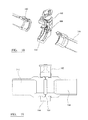
- a typical closure device as shown in FIGS. 17 to 19 can comprise a clamp 100 having an upper half 102 and a lower half 104 pulled together by two bolts 106 or actuators.
- the clamp 100 locates over the profile on both sides of the hub 108 formed by the contact of the two conduits 142 , 144 . This holds the interface between the fixed conduit 142 and the conduit 144 to be installed securely in position.
- the closure mechanism can be a single bolt clamp 110 .
- a clamp may comprise three segments 112 with the single bolt 114 fastening two of the segments 112 together while the remaining connection between the segments are hinge members 116 .
- the use of a single bolt clamp can allow the closure to be configured with the bolt at the top of the clamp, and a single tool can be used to apply torque to the bolt to operate the clamp. This is beneficial in a remote location as this simplifies the closing and tightening of the clamp.
- FIGS. 21 and 22 a secure closure device that can be used with the invention is shown in FIGS. 21 and 22 .
- the clamp 120 comprises a flexible metal band 122 joining a plurality of clamp segments 124 together and lugs located at each end of the band.
- a fastening mechanism including a single bolt 126 fastens the clamp lugs 128 together and is operated to open and close the clamp 120 .
- the fastening mechanism can comprise a removable cartridge block which houses at least part of the shaft of the bolt and the nut.
- the band provides flexibility in the clamp so it can be opened ( FIG. 22 ) and closed ( FIG. 21 ) sufficiently to allow the hub of the conduit to pass through the aperture formed by the band and clamp segments and to ensure that no moving parts will be located under the conduit.
- the clamp When the clamp is in an open position it allows the hub of the conduit being installed to pass through the clamp.
- the cartridge block can be sheared out of the lugs of the clamp removing the shaft and nut from the clamp as the cartridge is removed from the lug. This enables the bolt to be retrieved independently from the clamp. As the moveable parts required to operate the clamp are contained within the cartridge, this provides a closure mechanism whereby fallible components of the clamp operating mechanism are replaceable, or removable for refurbishment. This makes the device particularly suitable for use in remote locations where access for maintenance is difficult.
- the clamp retains the connection of the conduits in a closed position and the clamp segments are able to resist both internal and external loading that the connection may be subjected to throughout its service life. Providing a plurality of clamp segments that are spaced apart around the flexible band can help keep the weight and size of the clamp down.
- a conduit can be deployed to the connection tool with the clamp 120 already located on the second conduit. In a closed position the clamp fits closely around the circumference of the conduit.
- the connection tool can comprise an open top, components connected to the second conduit, such as the clamp, will not hinder the positioning of the second conduit into the tool.
- the clamp can be positioned on the conduit with the actuating mechanism retained on the top of the second conduit, such that no moving parts of the clamp will be located under the conduit when in the connection tool and the clamp can be easily accessed for the opening and closing of the clamp to secure the first and second conduits together. Locating the actuating mechanism on the top of the pipe also enables easier access for maintenance of the clamp operating mechanism.
- a vessel When laying a pipeline on the seabed a vessel is fitted with an open top channel such as a stinger, which guides the pipeline as it is deployed from the vessel down to the seabed.
- an open top channel such as a stinger
- the internal diameter of the channel is often only slightly larger than the external diameter of the pipeline to be deployed. This leads to a difficulty in fitting any further components to the outside of the pipe to be deployed together with the pipeline.
- the clamp can fit closely around the circumference of the pipeline with the actuating mechanism of the clamp located at the top of the conduit, such that the actuating mechanism extends out the top of the channel. This enables the pipeline with the clamp attached to be guided through the stinger as the pipeline is deployed from the vessel to the seabed. As the actuating mechanism can extend out towards the open top of the channel, the size of the actuating mechanism is not restricted by the diameter of the channel.
- a clamp can be used which provides sufficient strength to the connections to resist both internal and external loading that the connection may be subjected to.
Abstract
Description
-
- a frame assembly including a mounting point for mounting the end of the first conduit in a fixed position;
- a guide connected to the frame and including first and second guide formations for receiving guide arms attached to the end of the second conduits; and
- a moveable carrier mounted on the frame and including slots for engaging guide arms, the carrier being moveable between a first position in which the slots align with the guide formations so that the guide arms can pass into the slots, and a second position in which the end of the second conduit is held against the end of the first conduit so as to allow a connection to be formed to secure the ends together.
-
- a plurality of clamp segments;
- a flexible band in a substantially open circular shape connecting the segments;
- a clamp segment comprising a lug located at each end of the band; and
- an actuator extending through the lugs for opening and closing the clamp.
-
- assembling the end of the first conduit into the frame assembly into the mounting point;
- positioning the carrier in the first position;
- positioning the end of the second conduit in the guide;
- engaging first guide arms in the first guide formations;
pivoting the end of the second conduit around the first guide arms to engage second guide arms in the second guide formations; - moving the guide arms from the guide formations into the slots in the carrier;
- moving the carrier to the second position so as to move the end of the second conduit against the end of the first conduit; and
- forming a connection so as to secure the ends of the conduits together.
-
- attaching a clamp as described above to the second conduit;
- positioning the second conduit in an open top channel extending from the vessel such that the fastener of the clamp extends into the open top of the channel;
- guiding the second conduit through the channel; and
- connecting the second conduit to the first conduit using the apparatus as described above.
-
- assembling the end of the first conduit into the frame assembly into the mounting point;
- positioning the carrier in the first position;
- positioning the end of the second conduit in the guide;
- engaging first guide arms in the first guide formations;
- pivoting the end of the second conduit around the first guide arms to engage second guide arms in the second guide formations;
- moving the guide arms from the guide formations into the slots in the carrier;
- moving the carrier to the second position so as to move the end of the second conduit against the end of the first conduit; and
- forming a connection so as to secure the ends of the conduits together.
Claims (13)
Applications Claiming Priority (3)
| Application Number | Priority Date | Filing Date | Title |
|---|---|---|---|
| GB0905713A GB2469105B (en) | 2009-04-02 | 2009-04-02 | Apparatus and method for the connection of conduits |
| GB0905713.4 | 2009-04-02 | ||
| PCT/GB2010/050556 WO2010112920A1 (en) | 2009-04-02 | 2010-03-31 | Apparatus and method for the connection of conduits |
Publications (2)
| Publication Number | Publication Date |
|---|---|
| US20120090152A1 US20120090152A1 (en) | 2012-04-19 |
| US8832915B2 true US8832915B2 (en) | 2014-09-16 |
Family
ID=40749976
Family Applications (1)
| Application Number | Title | Priority Date | Filing Date |
|---|---|---|---|
| US13/262,615 Active 2030-12-23 US8832915B2 (en) | 2009-04-02 | 2010-03-31 | Apparatus and method for the connection of conduits |
Country Status (9)
| Country | Link |
|---|---|
| US (1) | US8832915B2 (en) |
| EP (1) | EP2414717B1 (en) |
| BR (1) | BRPI1012221A8 (en) |
| CY (1) | CY1114109T1 (en) |
| DK (1) | DK2414717T3 (en) |
| ES (1) | ES2421319T3 (en) |
| GB (1) | GB2469105B (en) |
| PT (1) | PT2414717E (en) |
| WO (1) | WO2010112920A1 (en) |
Cited By (4)
| Publication number | Priority date | Publication date | Assignee | Title |
|---|---|---|---|---|
| US9382780B1 (en) * | 2015-07-21 | 2016-07-05 | Chevron U.S.A. Inc. | Vertical swivel connection assembly and systems and methods for use thereof |
| US9890615B1 (en) * | 2017-03-09 | 2018-02-13 | Onesubsea Ip Uk Limited | Clamping system having mechanical advantage |
| US20180283151A1 (en) * | 2017-04-03 | 2018-10-04 | Fmc Technologies, Inc. | Fracturing manifold alignment systems |
| CN111649178A (en) * | 2020-03-02 | 2020-09-11 | 海洋石油工程股份有限公司 | Topside mounted subsea pipeline termination |
Families Citing this family (12)
| Publication number | Priority date | Publication date | Assignee | Title |
|---|---|---|---|---|
| GB2487423B (en) | 2011-01-21 | 2017-04-19 | Subsea 7 Ltd | Subsea connecting apparatus and method |
| US10995568B2 (en) * | 2011-08-09 | 2021-05-04 | FinalRod IP, LLC | Automated end fitting installation system and method |
| EP2722480B1 (en) * | 2012-10-17 | 2016-04-20 | Vetco Gray Scandinavia AS | Connection appliance and connection arrangement comprising such a connection appliance |
| GB2507269A (en) * | 2012-10-23 | 2014-04-30 | Wfs Technologies Ltd | Determining the spatial relationship between two surfaces |
| EP2746530B1 (en) * | 2012-12-21 | 2016-05-18 | Vetco Gray Scandinavia AS | Subsea arrangement |
| CN103090108B (en) * | 2013-02-21 | 2015-04-22 | 中国海洋石油总公司 | Simple and easy underwater flange installation machine |
| NL2010715C2 (en) * | 2013-04-26 | 2014-10-29 | Ihc Holland Ie Bv | Coupling device for dredging pipes and method for coupling dredging pipes. |
| NO337084B1 (en) * | 2013-12-19 | 2016-01-18 | Vetco Gray Scandinavia As | Connection system for underwater connection of an underwater control cable to an underwater device |
| NO338834B1 (en) * | 2014-09-19 | 2016-10-24 | Aker Subsea As | A handling device for an installable and retrievable underwater device |
| NO341571B1 (en) | 2014-10-13 | 2017-12-04 | Aker Solutions As | Connector at the top of the riser |
| CN106112479B (en) * | 2016-07-20 | 2024-01-12 | 梁启明 | Assembly quality of medical pipe and connecting pipe |
| CN108458181B (en) * | 2017-02-17 | 2024-03-26 | 中国石油天然气集团公司 | Quick connecting device for underwater equipment |
Citations (19)
| Publication number | Priority date | Publication date | Assignee | Title |
|---|---|---|---|---|
| US2548216A (en) | 1946-07-01 | 1951-04-10 | Marman Products Co Inc | Ventilated band clamp |
| US3059947A (en) | 1958-05-12 | 1962-10-23 | Aeroquip Corp | Ventilated band clamp |
| US3151373A (en) | 1961-04-14 | 1964-10-06 | Midland Ross Corp | Clamp for conduit couplings |
| US3775985A (en) * | 1972-04-20 | 1973-12-04 | Mc Dermott J & Co Inc | Apparatus for laying submarine pipelines |
| US4076130A (en) | 1976-02-27 | 1978-02-28 | Hydrotech International, Inc. | Apparatus for mounting a coupling member over a pipe end in a subsea location |
| US4915422A (en) * | 1989-01-06 | 1990-04-10 | The American Brass & Iron Foundry | Pipe coupling |
| US5206980A (en) * | 1992-04-07 | 1993-05-04 | Chapman Johnny D | Apparatus for aligning ends of pipes |
| US20010010782A1 (en) | 1997-04-03 | 2001-08-02 | Giovanni Corbetta | Method and apparatus for connecting underwater conduits |
| US20020014772A1 (en) | 2000-06-23 | 2002-02-07 | Amedure Michael E. | Pipe coupler |
| WO2003050443A1 (en) | 2001-12-11 | 2003-06-19 | Kværner Oilfield Products As | A subsea tool for tie in of pipeline ends |
| US20050258641A1 (en) * | 2004-05-14 | 2005-11-24 | Victaulic Company Of America | Pipe coupling having compression band |
| GB2417534A (en) | 2003-05-28 | 2006-03-01 | Vetco Aibel As | A spool piece termination structure, a connection arrangement comprising such a termination structure and a pipeline termination |
| US20070126234A1 (en) | 2005-12-01 | 2007-06-07 | Georg Wirth | Clamp |
| US20070269270A1 (en) * | 2004-06-30 | 2007-11-22 | Rolf Bastesen | Pipeline Termination Skid, a Connection Arrangement Comprising Such a Pipeline Termination Skid and a Pipeline Termination |
| GB2440808A (en) | 2006-08-10 | 2008-02-13 | Subsea 7 Ltd | Method of installing subsea equipment with a support frame |
| GB2442972A (en) | 2006-07-27 | 2008-04-23 | Verderg Connectors Ltd | Split locating sleeve provides increased area for engagement |
| WO2008063080A1 (en) | 2006-11-22 | 2008-05-29 | Aker Subsea As | A connector means |
| WO2009092240A1 (en) | 2007-12-29 | 2009-07-30 | Shenzhen Huawei Communication Technologies Co., Ltd. | A communication device and application method, system thereof |
| EP1956184B1 (en) | 2007-02-09 | 2011-06-08 | Subsea 7 Norway NUF | Method and apparatus for pipeline connection |
Family Cites Families (1)
| Publication number | Priority date | Publication date | Assignee | Title |
|---|---|---|---|---|
| NO329288B1 (en) * | 2007-12-21 | 2010-09-27 | Fmc Kongsberg Subsea As | Tool and method for connection of pipelines |
-
2009
- 2009-04-02 GB GB0905713A patent/GB2469105B/en not_active Expired - Fee Related
-
2010
- 2010-03-31 DK DK10712765.6T patent/DK2414717T3/en active
- 2010-03-31 EP EP10712765.6A patent/EP2414717B1/en not_active Not-in-force
- 2010-03-31 BR BRPI1012221A patent/BRPI1012221A8/en not_active IP Right Cessation
- 2010-03-31 ES ES10712765T patent/ES2421319T3/en active Active
- 2010-03-31 WO PCT/GB2010/050556 patent/WO2010112920A1/en active Application Filing
- 2010-03-31 PT PT107127656T patent/PT2414717E/en unknown
- 2010-03-31 US US13/262,615 patent/US8832915B2/en active Active
-
2013
- 2013-07-04 CY CY20131100560T patent/CY1114109T1/en unknown
Patent Citations (21)
| Publication number | Priority date | Publication date | Assignee | Title |
|---|---|---|---|---|
| US2548216A (en) | 1946-07-01 | 1951-04-10 | Marman Products Co Inc | Ventilated band clamp |
| US3059947A (en) | 1958-05-12 | 1962-10-23 | Aeroquip Corp | Ventilated band clamp |
| US3151373A (en) | 1961-04-14 | 1964-10-06 | Midland Ross Corp | Clamp for conduit couplings |
| US3775985A (en) * | 1972-04-20 | 1973-12-04 | Mc Dermott J & Co Inc | Apparatus for laying submarine pipelines |
| US4076130A (en) | 1976-02-27 | 1978-02-28 | Hydrotech International, Inc. | Apparatus for mounting a coupling member over a pipe end in a subsea location |
| US4915422A (en) * | 1989-01-06 | 1990-04-10 | The American Brass & Iron Foundry | Pipe coupling |
| US5206980A (en) * | 1992-04-07 | 1993-05-04 | Chapman Johnny D | Apparatus for aligning ends of pipes |
| US20010010782A1 (en) | 1997-04-03 | 2001-08-02 | Giovanni Corbetta | Method and apparatus for connecting underwater conduits |
| US20020014772A1 (en) | 2000-06-23 | 2002-02-07 | Amedure Michael E. | Pipe coupler |
| WO2003050443A1 (en) | 2001-12-11 | 2003-06-19 | Kværner Oilfield Products As | A subsea tool for tie in of pipeline ends |
| US6997645B2 (en) * | 2001-12-11 | 2006-02-14 | Kvaerner Oilfield Products As | Subsea tool for tie in of pipeline ends |
| US20070009328A1 (en) * | 2003-05-28 | 2007-01-11 | Vetco Aibel As | Spool piece termination structure, a connection arrangement comprising such a termination structure and a pipeline termination |
| GB2417534A (en) | 2003-05-28 | 2006-03-01 | Vetco Aibel As | A spool piece termination structure, a connection arrangement comprising such a termination structure and a pipeline termination |
| US20050258641A1 (en) * | 2004-05-14 | 2005-11-24 | Victaulic Company Of America | Pipe coupling having compression band |
| US20070269270A1 (en) * | 2004-06-30 | 2007-11-22 | Rolf Bastesen | Pipeline Termination Skid, a Connection Arrangement Comprising Such a Pipeline Termination Skid and a Pipeline Termination |
| US20070126234A1 (en) | 2005-12-01 | 2007-06-07 | Georg Wirth | Clamp |
| GB2442972A (en) | 2006-07-27 | 2008-04-23 | Verderg Connectors Ltd | Split locating sleeve provides increased area for engagement |
| GB2440808A (en) | 2006-08-10 | 2008-02-13 | Subsea 7 Ltd | Method of installing subsea equipment with a support frame |
| WO2008063080A1 (en) | 2006-11-22 | 2008-05-29 | Aker Subsea As | A connector means |
| EP1956184B1 (en) | 2007-02-09 | 2011-06-08 | Subsea 7 Norway NUF | Method and apparatus for pipeline connection |
| WO2009092240A1 (en) | 2007-12-29 | 2009-07-30 | Shenzhen Huawei Communication Technologies Co., Ltd. | A communication device and application method, system thereof |
Non-Patent Citations (1)
| Title |
|---|
| International Search Report, mailed Aug. 3, 2010, for PCT/GB2010/050556, 5 pages. |
Cited By (4)
| Publication number | Priority date | Publication date | Assignee | Title |
|---|---|---|---|---|
| US9382780B1 (en) * | 2015-07-21 | 2016-07-05 | Chevron U.S.A. Inc. | Vertical swivel connection assembly and systems and methods for use thereof |
| US9890615B1 (en) * | 2017-03-09 | 2018-02-13 | Onesubsea Ip Uk Limited | Clamping system having mechanical advantage |
| US20180283151A1 (en) * | 2017-04-03 | 2018-10-04 | Fmc Technologies, Inc. | Fracturing manifold alignment systems |
| CN111649178A (en) * | 2020-03-02 | 2020-09-11 | 海洋石油工程股份有限公司 | Topside mounted subsea pipeline termination |
Also Published As
| Publication number | Publication date |
|---|---|
| EP2414717A1 (en) | 2012-02-08 |
| CY1114109T1 (en) | 2016-10-05 |
| ES2421319T3 (en) | 2013-08-30 |
| BRPI1012221A8 (en) | 2016-09-27 |
| US20120090152A1 (en) | 2012-04-19 |
| GB0905713D0 (en) | 2009-05-20 |
| DK2414717T3 (en) | 2013-07-08 |
| GB2469105B (en) | 2011-06-22 |
| WO2010112920A1 (en) | 2010-10-07 |
| PT2414717E (en) | 2013-07-18 |
| EP2414717B1 (en) | 2013-05-01 |
| GB2469105A (en) | 2010-10-06 |
| BRPI1012221A2 (en) | 2016-03-29 |
Similar Documents
| Publication | Publication Date | Title |
|---|---|---|
| US8832915B2 (en) | Apparatus and method for the connection of conduits | |
| US20210246735A1 (en) | Pipeline integrated manifold | |
| US6767165B1 (en) | Method and apparatus for connecting underwater conduits | |
| EP2547937B1 (en) | Sub-sea apparatus and operating method | |
| US8408842B2 (en) | Connection arrangement for subsea connection of fluid conduits | |
| US9163486B2 (en) | Subsea structure flowline connector assembly | |
| EP2791461B1 (en) | Subsea structure flowline connector assembly | |
| US8939702B2 (en) | Sub-sea apparatus and operating method | |
| EP2652253B1 (en) | Connection apparatus and methods | |
| US20210164588A1 (en) | Subsea pipeline with multiple access nodes | |
| WO1995031669A1 (en) | A method of laying a pipeline | |
| Møllerop et al. | Deepwater Development Using Novel Diverless Flowline Connection Technology | |
| Jansen et al. | Norne-Heidrun: Closing" The Loop" With Diverless Flanged Connections |
Legal Events
| Date | Code | Title | Description |
|---|---|---|---|
| AS | Assignment |
Owner name: VERDERG LTD, UNITED KINGDOM Free format text: ASSIGNMENT OF ASSIGNORS INTEREST;ASSIGNOR:WHITE, JOHN;REEL/FRAME:027425/0438 Effective date: 20111216 |
|
| AS | Assignment |
Owner name: VERDERG CONNECTORS LIMITED, UNITED KINGDOM Free format text: ASSIGNMENT OF ASSIGNORS INTEREST;ASSIGNOR:VERDERG LTD;REEL/FRAME:029166/0044 Effective date: 20121015 |
|
| STCF | Information on status: patent grant |
Free format text: PATENTED CASE |
|
| FEPP | Fee payment procedure |
Free format text: PAT HOLDER NO LONGER CLAIMS SMALL ENTITY STATUS, ENTITY STATUS SET TO UNDISCOUNTED (ORIGINAL EVENT CODE: STOL); ENTITY STATUS OF PATENT OWNER: LARGE ENTITY |
|
| FEPP | Fee payment procedure |
Free format text: PAT HOLDER CLAIMS SMALL ENTITY STATUS, ENTITY STATUS SET TO SMALL (ORIGINAL EVENT CODE: LTOS); ENTITY STATUS OF PATENT OWNER: LARGE ENTITY |
|
| AS | Assignment |
Owner name: AFGLOBAL UK LIMITED, UNITED KINGDOM Free format text: CHANGE OF NAME;ASSIGNOR:VERDERG CONNECTORS LIMITED;REEL/FRAME:040529/0862 Effective date: 20160602 |
|
| MAFP | Maintenance fee payment |
Free format text: PAYMENT OF MAINTENANCE FEE, 4TH YEAR, LARGE ENTITY (ORIGINAL EVENT CODE: M1551) Year of fee payment: 4 |
|
| FEPP | Fee payment procedure |
Free format text: MAINTENANCE FEE REMINDER MAILED (ORIGINAL EVENT CODE: REM.); ENTITY STATUS OF PATENT OWNER: LARGE ENTITY |
|
| FEPP | Fee payment procedure |
Free format text: 7.5 YR SURCHARGE - LATE PMT W/IN 6 MO, LARGE ENTITY (ORIGINAL EVENT CODE: M1555); ENTITY STATUS OF PATENT OWNER: LARGE ENTITY |
|
| MAFP | Maintenance fee payment |
Free format text: PAYMENT OF MAINTENANCE FEE, 8TH YEAR, LARGE ENTITY (ORIGINAL EVENT CODE: M1552); ENTITY STATUS OF PATENT OWNER: LARGE ENTITY Year of fee payment: 8 |