US8800949B2 - Vehicle seat memory track assembly with external release - Google Patents
Vehicle seat memory track assembly with external release Download PDFInfo
- Publication number
- US8800949B2 US8800949B2 US13/983,326 US201113983326A US8800949B2 US 8800949 B2 US8800949 B2 US 8800949B2 US 201113983326 A US201113983326 A US 201113983326A US 8800949 B2 US8800949 B2 US 8800949B2
- Authority
- US
- United States
- Prior art keywords
- seat
- pair
- rail
- track
- activation
- Prior art date
- Legal status (The legal status is an assumption and is not a legal conclusion. Google has not performed a legal analysis and makes no representation as to the accuracy of the status listed.)
- Active
Links
Images


Classifications
-
- B—PERFORMING OPERATIONS; TRANSPORTING
- B60—VEHICLES IN GENERAL
- B60N—SEATS SPECIALLY ADAPTED FOR VEHICLES; VEHICLE PASSENGER ACCOMMODATION NOT OTHERWISE PROVIDED FOR
- B60N2/00—Seats specially adapted for vehicles; Arrangement or mounting of seats in vehicles
- B60N2/02—Seats specially adapted for vehicles; Arrangement or mounting of seats in vehicles the seat or part thereof being movable, e.g. adjustable
- B60N2/04—Seats specially adapted for vehicles; Arrangement or mounting of seats in vehicles the seat or part thereof being movable, e.g. adjustable the whole seat being movable
- B60N2/06—Seats specially adapted for vehicles; Arrangement or mounting of seats in vehicles the seat or part thereof being movable, e.g. adjustable the whole seat being movable slidable
- B60N2/07—Slide construction
- B60N2/0722—Constructive details
-
- B—PERFORMING OPERATIONS; TRANSPORTING
- B60—VEHICLES IN GENERAL
- B60N—SEATS SPECIALLY ADAPTED FOR VEHICLES; VEHICLE PASSENGER ACCOMMODATION NOT OTHERWISE PROVIDED FOR
- B60N2/00—Seats specially adapted for vehicles; Arrangement or mounting of seats in vehicles
- B60N2/02—Seats specially adapted for vehicles; Arrangement or mounting of seats in vehicles the seat or part thereof being movable, e.g. adjustable
- B60N2/04—Seats specially adapted for vehicles; Arrangement or mounting of seats in vehicles the seat or part thereof being movable, e.g. adjustable the whole seat being movable
- B60N2/06—Seats specially adapted for vehicles; Arrangement or mounting of seats in vehicles the seat or part thereof being movable, e.g. adjustable the whole seat being movable slidable
- B60N2/07—Slide construction
- B60N2/0702—Slide construction characterised by its cross-section
- B60N2/0705—Slide construction characterised by its cross-section omega-shaped
-
- B—PERFORMING OPERATIONS; TRANSPORTING
- B60—VEHICLES IN GENERAL
- B60N—SEATS SPECIALLY ADAPTED FOR VEHICLES; VEHICLE PASSENGER ACCOMMODATION NOT OTHERWISE PROVIDED FOR
- B60N2/00—Seats specially adapted for vehicles; Arrangement or mounting of seats in vehicles
- B60N2/02—Seats specially adapted for vehicles; Arrangement or mounting of seats in vehicles the seat or part thereof being movable, e.g. adjustable
- B60N2/04—Seats specially adapted for vehicles; Arrangement or mounting of seats in vehicles the seat or part thereof being movable, e.g. adjustable the whole seat being movable
- B60N2/06—Seats specially adapted for vehicles; Arrangement or mounting of seats in vehicles the seat or part thereof being movable, e.g. adjustable the whole seat being movable slidable
- B60N2/07—Slide construction
- B60N2/0702—Slide construction characterised by its cross-section
- B60N2/0715—C or U-shaped
-
- B—PERFORMING OPERATIONS; TRANSPORTING
- B60—VEHICLES IN GENERAL
- B60N—SEATS SPECIALLY ADAPTED FOR VEHICLES; VEHICLE PASSENGER ACCOMMODATION NOT OTHERWISE PROVIDED FOR
- B60N2/00—Seats specially adapted for vehicles; Arrangement or mounting of seats in vehicles
- B60N2/02—Seats specially adapted for vehicles; Arrangement or mounting of seats in vehicles the seat or part thereof being movable, e.g. adjustable
- B60N2/04—Seats specially adapted for vehicles; Arrangement or mounting of seats in vehicles the seat or part thereof being movable, e.g. adjustable the whole seat being movable
- B60N2/06—Seats specially adapted for vehicles; Arrangement or mounting of seats in vehicles the seat or part thereof being movable, e.g. adjustable the whole seat being movable slidable
- B60N2/08—Seats specially adapted for vehicles; Arrangement or mounting of seats in vehicles the seat or part thereof being movable, e.g. adjustable the whole seat being movable slidable characterised by the locking device
- B60N2/0812—Location of the latch
- B60N2/0818—Location of the latch inside the rail
-
- B—PERFORMING OPERATIONS; TRANSPORTING
- B60—VEHICLES IN GENERAL
- B60N—SEATS SPECIALLY ADAPTED FOR VEHICLES; VEHICLE PASSENGER ACCOMMODATION NOT OTHERWISE PROVIDED FOR
- B60N2/00—Seats specially adapted for vehicles; Arrangement or mounting of seats in vehicles
- B60N2/02—Seats specially adapted for vehicles; Arrangement or mounting of seats in vehicles the seat or part thereof being movable, e.g. adjustable
- B60N2/04—Seats specially adapted for vehicles; Arrangement or mounting of seats in vehicles the seat or part thereof being movable, e.g. adjustable the whole seat being movable
- B60N2/06—Seats specially adapted for vehicles; Arrangement or mounting of seats in vehicles the seat or part thereof being movable, e.g. adjustable the whole seat being movable slidable
- B60N2/08—Seats specially adapted for vehicles; Arrangement or mounting of seats in vehicles the seat or part thereof being movable, e.g. adjustable the whole seat being movable slidable characterised by the locking device
- B60N2/0831—Movement of the latch
- B60N2/0837—Movement of the latch pivoting
- B60N2/0843—Movement of the latch pivoting about a longitudinal axis
-
- B—PERFORMING OPERATIONS; TRANSPORTING
- B60—VEHICLES IN GENERAL
- B60N—SEATS SPECIALLY ADAPTED FOR VEHICLES; VEHICLE PASSENGER ACCOMMODATION NOT OTHERWISE PROVIDED FOR
- B60N2/00—Seats specially adapted for vehicles; Arrangement or mounting of seats in vehicles
- B60N2/02—Seats specially adapted for vehicles; Arrangement or mounting of seats in vehicles the seat or part thereof being movable, e.g. adjustable
- B60N2/04—Seats specially adapted for vehicles; Arrangement or mounting of seats in vehicles the seat or part thereof being movable, e.g. adjustable the whole seat being movable
- B60N2/12—Seats specially adapted for vehicles; Arrangement or mounting of seats in vehicles the seat or part thereof being movable, e.g. adjustable the whole seat being movable slidable and tiltable
- B60N2/123—Seats specially adapted for vehicles; Arrangement or mounting of seats in vehicles the seat or part thereof being movable, e.g. adjustable the whole seat being movable slidable and tiltable and provided with memory locks
Definitions
- Vehicles such as passenger cars typically include seats for the use of the driver and other occupants. In many vehicles, the position of the seats may be adjusted for the comfort of the occupants. Adjustment options, particularly for the first row of seats, typically include the capability to move the seat in fore and aft directions by operation of a track assembly which mounts the seat to the vehicle floor.
- These existing systems typically employ a generally U-shaped comfort adjustment bar (also known as a “towel bar”) which is operatively connected to the seat track locking system.
- Each of the legs of the U shaped towel bar extend, respectively, into the openings formed between first and second sets of upper and lower tracks, with one or more of the ends operatively connected to release the track locking system to unlock the seat from the lower track when the end portion of the towel bar is raised, thereby allowing the occupant to slidably position the seat along the length of the tracks as desired.
- One such adjustable seat track assembly is disclosed in PCT Publication No. WO 2010/080597 A1.
- Some vehicle seats may include the capability of folding the seatback forward then sliding the entire seat forward to facilitate access to the second row of seats. This is known as an “easy entry” option, and is commonly seen in two-door vehicles.
- the easy entry option allows the generally upright back portion of the seat to be dumped, or pivoted, forward from its normal position, at the same time unlocking the seat to allow the seat to be slidably positioned forward in the passenger compartment to provide more spaced behind the seat to gain entrance into the second row of seats.
- Seats which include an easy entry capability may also include a memory system, typically disposed in one of the pair of seat tracks, and configured to remember a longitudinal position of the corresponding upper track with respect to the corresponding lower track such that, whenever the seatback is dumped forward and the seat slid forward for easy entry to the second row, and the seat is thereafter slidably positioned rearward for use by the front row occupant, the sliding seat automatically stops and locks at the previously selected use position.
- Vehicle seats including easy entry capabilities with position memory systems are disclosed in PCT Publication No. WO 2010/080593 A1.
- the disclosed system includes a vehicle seat memory track assembly including two pairs of upper and lower seat rails that are positioned on opposite sides of a seat bottom of a vehicle seat. Each lower rail is fixedly attachable to a vehicle support structure, such as a vehicle floor, and each upper rail is fixedly attachable to the seat bottom and slidably mounted in a respective lower seat rail.
- the disclosed system further includes a seat track locking system including two track locking assemblies, each one disposed in one of the pairs of tracks, and each track locking assembly being configured to lock a respective upper rail in a variety of longitudinal positions with respect to its corresponding lower rail.
- a first actuator is operably connected to the seat track locking system.
- the first actuator includes a release lever positioned externally to the nested upper and lower seat rail pairs and operably connected to an activation bracket, which is movable from a non-activated position to an activated position, whereby the activation bracket disengages the seat track locking system to allow slidable longitudinal movement of the seat to a different desired seating position.
- the disclosed system includes a memory system which is mounted on one of the upper rails and is engageable with the corresponding lower rail whenever the memory system is activated, such as when the seatback is folded forward and the seat slidably positioned forward to allow an occupant to gain entry to the second row of seats.
- the memory system records the longitudinal travel of the seat, so that after entry to the second row is gained and the operator slides the seat rearward along the lower rails, the memory system stops the seat at the same use position that the seat was in prior to folding and moving the seat for easy entry.
- the memory system is operable via a second actuator which includes an activation lever mounted externally of one of the pair of rails for movement from a disengaged position to an engaged position with the other of the pair of rails in which the memory module is activated to record the use position from which the seat may then subsequently be moved to allow for entry into the second row of seats.
- the activation lever is also operably connected to the first actuator to disengage the seat track locking system when the memory system is activated, to allow forward movement of the seat from the user-selected location to a more forward location, and thereafter allow rearward movement of the seat back to, but not past, the user-selected location.
- FIG. 1 is a rear perspective view of a bucket seat
- FIG. 2 is a perspective view of the one embodiment of the disclosed vehicle seat memory track assembly
- FIG. 3 is a perspective view of a portion of the seat track assembly of FIG. 2 , showing the track lock activation member;
- FIG. 4 is a perspective view of the disclosed memory module
- FIG. 5 is a lower view (when installed) of the memory module
- FIG. 6 is an isolated view of the memory module gear wheel, end stop, spindle, and memory nut
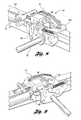
- FIG. 7 is a partial perspective view of a portion of the track assembly (on the non-memory side) showing a portion of the seat track locking system release mechanism;
- FIG. 8 is a partial forward perspective view of a portion of the track assembly (on the memory system side);
- FIG. 9 is a partial rearward perspective view of the portion of the track assembly shown in FIG. 8 ;
- FIG. 10 is a side elevation overview of a portion of the track assembly (on the memory system side);
- FIG. 11 is a side elevational cross-sectional view of the track assembly (on the memory system side) showing the memory system moving from the non-activated to the activated position;
- FIG. 12 is a side elevational view of the track assembly (on the memory system side) from the opposite side of the track shown in FIG. 11 ;
- FIG. 13 is a side elevational cross-sectional view of the track assembly (on the memory system side) showing the memory system in the activated position;
- FIG. 14 is a side elevational view of the track assembly (on the memory system side) from the opposite side of the track shown in FIG. 13 ;
- FIG. 15 is a side cross-sectional view of the track assembly (on the memory system side) showing the memory system as it is being deactivated;
- FIG. 16 is a side view of the track assembly (on the memory system side) from the opposite side of the track shown in FIG. 15 ;
- FIG. 17 is a side cross-sectional view of the track assembly (on the memory system side) showing the memory system in the deactivated position;
- FIG. 18 is a side elevational view of the track assembly (on the memory system side) from the opposite side of the track shown in FIG. 17 ;
- FIG. 19 is an elevational view of the track assembly (on the memory system side) from the side of the track shown in FIG. 18 , showing the relative positions of the activation bracket, activation lever, and the reset lever when the memory system is reset by operating the release lever;
- FIG. 20 is an elevational view of the track assembly (on the memory system side) from the side of the track shown in FIG. 18 , showing the relative positions of the activation bracket, activation lever, and the reset lever when the backrest is dumped forward and the activation lever has been rotated rearward by the Bowden cable.
- the disclosed vehicle seat memory track assembly may be used with a vehicle seat, such as bucket seat 10 , or other similar type seat commonly installed as the front row of seats in a vehicle.
- the bucket seat 10 includes a seat portion 12 and a backrest 14 .
- Each of the seat portion 12 and the backrest 14 may be cushioned and upholstered with a suitable fabric, vinyl, or leather cover for aesthetics and the comfort of the seat occupants.
- the backrest 14 may be attached for pivotal rotation relative to the seat portion 12 to provide a variety of inclination positions for the seeded occupant.
- the backrest 14 may also be rotatable between an inclined, use position and a collapsed (or dumped) position, folded forward over the seat portion 12 to provide more space within the vehicle for ingress, egress, or stowage.
- the pivotal movement of the backrest 14 relative to the seat portion 12 may be accomplished by actuating one of one or more handles 16 which are operably connected to a backrest adjustment mechanism (not shown) to adjust the inclination of, and/or dump, the backrest 14 .
- the seat track memory system may include at least one pair of upper and lower rails, 18 and 20 respectively.
- the seat track memory system includes two pairs of upper and lower rails, 18 , 20 and 18 a , 20 a , arranged in a spaced-apart, generally parallel configuration on opposite sides of the seat bottom 12 .
- Each lower rail 20 , 20 a is fixedly attached to a vehicle support structure, such as a vehicle floor.
- Each upper rail 18 , 18 a is fixedly attached to the seat bottom 12 and slidably mounted in a respective lower seat rail 20 , 20 a for movement of the upper rails 18 , 18 a and, thus, the seat, relative to the floor of the vehicle.
- the disclosed system includes a seat track locking system including at least one locking assembly 24 (shown in FIG. 3 ) connected to one of the pair of upper and lower rails and operable to lock the upper rail 18 from movement with respect to the lower rail 20 when the locking assembly 24 is engaged.
- the disclosed system employs a pair of locking assemblies (each as shown as 26 in FIG.
- a first actuator is operably connected to the seat track locking system, and is movable between a non-activated position and then activated position whereby the seat track locking system is disengaged to allow slidable longitudinal movement of the seat.
- the first actuator includes a release lever 28 , which may include a handle 30 attached at the outboard end (i.e., the end nearest the forward edge of the seat bottom 12 ).
- the release lever 28 is attached at its inboard end to a crossbar (or tube) 32 that is rotatably connected at each end, respectively, to support brackets 36 , 36 a , which support brackets 36 , 36 a are fixedly secured (such as, for example, by welding) to their corresponding upper rails 18 , 18 a .
- the release lever 28 is fixedly connected to the crossbar 32 such that upward lifting of the lever handle 30 rotates crossbar 32 .
- the first actuator also includes an activation bracket 34 , 34 a associated with each pair of upper and lower rails.
- Each activation bracket 34 , 34 a is fixedly mounted on the end of the crossbar 32 adjacent and exterior to its associated pair of upper and lower rails for rotation from a first, disengaged position (shown, for example, in FIG. 12 ) to a second, engaged position (as shown, for example, in FIGS.
- each activation bracket 34 , 34 a presses an activation button 38 which is connected to each track locking assembly 24 associated with each pair of upper and lower rails, and which, when depressed, causes each track locking assembly 24 to disengage, allowing rails 18 , 18 a to be slidably positioned with respect to rails 20 , 20 a.
- the disclosed release lever 28 can be fabricated of metal or rigid plastic and formed with a tubular or u-shaped cross-section that is relatively larger in cross-section than prior towel bar-type actuators, since the release lever 28 is mounted externally of the upper and lower rail pairs, rather than extending into the opening between a nested upper and lower rail pair. This provides a firmer, more robust feel for the operator. Also, since the release lever 28 is mounted externally of the upper and lower rail pair, the lever can be moved over a wider angle of rotation during activation than prior towel bar-type actuators, which are typically nested within, and confined by, the upper and lower rails, and therefore provide a relatively limited range of motion within the rail pair.
- the disclosed system includes a memory system, generally indicated as 40 , mounted on one of the upper lower pairs of rails 18 a , 20 a which, when engaged, disengages the track locking system, and records the last use position of the vehicle seat to allow for forward movement of the seat from the user selected location to a more forward location (such as, for example, when the backrest 14 is dumped to allow ingress or egress to or from, respectively, a rearward seat), and thereafter return rearward to, but not past, the recorded user-selected location.
- a memory system mounted on one of the upper lower pairs of rails 18 a , 20 a which, when engaged, disengages the track locking system, and records the last use position of the vehicle seat to allow for forward movement of the seat from the user selected location to a more forward location (such as, for example, when the backrest 14 is dumped to allow ingress or egress to or from, respectively, a rearward seat), and thereafter return rearward to, but not past, the recorded user-selected location.
- the disclosed memory system 40 includes a sled 42 , mounted for slidable movement on mounting bracket 36 a , which mounting bracket 36 a is fixedly secured to upper rail 18 a .
- Memory system 40 also includes a second actuator which may include an activation lever 44 which is pivotally mounted on activation bracket 34 a and includes a guide post 46 which extends across the top surface of the upper rail 18 a .
- the activation lever 44 is biased by spring member 50 into a refracted position (as shown in FIGS. 2 and 9 ) when the memory system 40 is deactivated.
- a Bowden cable 52 connects the activation lever 44 to the back rest 14 such that, when the back rest 14 is dumped forward, the Bowden cable is refracted, thereby pulling the activation lever 44 rearward (i.e., toward the back of the seat).
- the guide post 46 on the activation lever 44 moves into contact with the facing surface 48 of the sled 42 , thereby slidably positioning the sled in a rearward direction.
- the disclosed system employs the Bowden cable 52 and sled 42 in an orientation in which the cable retracts, and the sled moves, in a rearward direction to activate the memory system 40
- the disclosed orientation of these components may be altered or reversed to facilitate these motions in the forward direction to activate the memory system 40 .
- components which are described in this disclosure as moving “downward” or “upward” in their operation may alternatively be oriented such that they perform the described functions through motions in the direction opposite from the directions disclosed in the specific embodiments described herein.
- activation lever 44 when the seat back 14 is dumped forward and the Bowden cable actuates activation lever 44 to urge sled 42 towards the activated position, activation lever 44 is simultaneously brought into contact with activation bracket 34 a .
- activation lever 44 rotates rearward it bears upon activation bracket 34 a (at location 46 , shown in FIG. 14 ) rotating activation bracket 34 a into position to depress actuation button 38 , thereby releasing the seat track lock system.
- the rotation of activation lever 44 simultaneously moves the sled 42 of the memory system into activated position, while simultaneously causing disengagement of the seat track locking system 24 , thereby allowing for slidable movement of the dumped seat.
- the memory system also includes a memory module 54 disposed in one of the pairs of tracks 18 a , 20 a (hereinafter also referred to as the first pair of tracks).
- the memory module 54 When activated, the memory module 54 is configured to record the travel of the upper track 18 a with respect to the lower track 20 a , thereby remembering a longitudinal position of the corresponding upper track with respect to the lower track.
- the memory module 54 is pivotally connected to a pivot bracket 56 , which is fixed to the first upper track 18 a .
- the memory module 54 is pivotable between a raised, non-activated position (shown in FIG. 17 ) and a lowered, activated position (shown in FIGS. 11 , 13 , and 15 ).
- the memory module 54 also includes a spring 56 that biases the memory module 54 toward the raised, non-activated position.
- the memory module 54 includes a track wheel assembly including a track gear wheel 60 rotatably mounted on a wheel support bracket 62 .
- the wheel support bracket 62 is pivotally mounted on the pivot bracket 56 .
- the track gear wheel 60 is rotatably engageable with the first lower track 20 a (see FIGS. 11 , 13 , and 15 ) when the memory module 54 is moved to the activated position.
- the track gear wheel 60 includes a plurality of gear teeth 64 that are configured to extend into notches 66 formed in the first lower track 20 a as the track gear wheel 60 moves with respect to the first lower track 20 a.
- the track gear wheel 60 is also connected to a threaded spindle 64 that receives a threaded memory nut 66 .
- the memory nut 66 has an end stop (not shown) that engages an end stop of the track gear wheel 60 when the memory module is in the memorized position (for example, when the seat has been again moved rearward to its selected use position after the backrest has been dumped and the seat moved forward for ingress or egress to or from the second row seats).
- the memory module 54 may also include a clock spring (not shown) having one end engaged with the track gear wheel 60 and an opposite end engaged with a plastic disc that is fixed with respect to the wheel support bracket 62 on which the track gear wheel 60 is mounted, such that the clock spring urges the track gear wheel 60 toward an initial position into engagement with the memory nut 66 .
- a clock spring (not shown) having one end engaged with the track gear wheel 60 and an opposite end engaged with a plastic disc that is fixed with respect to the wheel support bracket 62 on which the track gear wheel 60 is mounted, such that the clock spring urges the track gear wheel 60 toward an initial position into engagement with the memory nut 66 .
- the track gear wheel 60 is disengaged from the first lower track 20 a , and the position of the first upper track 18 a may be fixed with respect to the first lower track by the track locking system (as shown in FIGS. 8 and 9 ).
- the memory module 54 is activated by pivoting the seat back 14 of the vehicle seat forward, each of the track locking assemblies 26 , 26 a are move from a locked (or engaged) position to a released (or disengaged) position, and the memory module 54 is pivoted downward into the activated position.
- this activation of the memory module is accomplished by actuation of the second actuator.
- the memory module 54 activation system includes a reset lever 68 , which is movably mounted on the support bracket 36 a and engageable with the sled 42 .
- reset lever 68 is retained in a lowered, non-interference position with respect to the sled 42 .
- the reset lever 68 is urged upward by the resilient spring element 70 into the recess 72 on the underside of the sled 42 , as is shown in FIGS. 15 and 16 .
- FIGS. 8 and 9 show the memory system 40 in the deactivated condition, such as when the backrest is upright and the seat is locked in a preferred use position on the track assembly.
- FIG. 10 shows the sled 42 biased by spring member 50 in the de-activated position, and the reset lever 68 in its depressed, interactive position.
- memory module 54 is pivoted upward into its non-activated position by virtue of biasing spring 56 , whereby track gear wheel 60 is disengaged from the lower track 20 a (as shown in FIG. 17 ).
- the seatback 14 is pivoted forwardly (or dumped) causing the Bowden cable which interconnects a location on the frame of the backrest to the activation lever 44 to rotate the activation lever, causing the guidepost 46 to contact sled contact surface 48 and urge the sled 42 from its de-activated position rearward to its activated position.
- FIGS. 11 and 12 show the relative positions of the memory system 40 components as the seatback 14 is pivoted forwardly and the memory system is moving from the de-activated condition to the activated condition as activation lever 44 is rotated by the Bowden cable, sled 42 slides rearward (in the direction shown by arrow 73 in FIG. 11 ). As this sled 42 slides rearward, memory module engagement surface 74 contacts a projection 76 formed on the memory module and moves the memory module downward to its activated position, as shown in FIG. 11 . After a sufficient amount of rotation of the activating lever 44 , the lever 44 also engages the activation bracket 34 a so that both the activating lever 44 and the actuation bracket 34 a rotate together.
- the activation bracket 34 a on the memory side is linked with the activation bracket 34 on the non-memory side, rotation of the activation bracket 34 a on the memory side, rotates the crossbar 32 and causes the activation bracket 34 on the non-memory side to rotate as well.
- each of the activation brackets 34 , 34 a engage and the press their respective activating buttons 38 , causing disengagement of each of the track locking assemblies, thereby releasing the track locking system.
- FIGS. 13 and 14 illustrate the memory system 40 in the activated position.
- one end of the reset lever 68 moves upward into the recess 72 on the underside of the sled 42 .
- the engaged track gear wheel 60 rotates along the first lower track 20 a , causing the memory nut 66 to move along the threaded spindle 64 away from the gear wheel 60 .
- the memory nut travels back on the threaded spindle toward the gear wheel until the associated and stops on the memory nut and the gear wheel engage each other, thereby preventing further rearward movement of the vehicle seat bottom and upper tracks 18 , 18 a with respect to the lower tracks 20 , 20 a.
- this disclosed arrangement allows the user to dump the backrest, slide the seat forward, slide the seat back to a position short of the memorized (or originally set) use position, raise the backrest, and lock the seat for use at a position less rearward than the memorized position (such as, for example, when a passenger has occupied the rearward seat, and the front seat passenger wishes to temporarily re-position and lock the front seat at a more forward position to give the rearward passenger more legroom).
- the backrest may again be dumped forward, thereby disengaging the track locking system, and, since the memory system 40 has not been reset, sliding the seat rearward until further rearward movement is prevented by the memory module 54 as previously described.
- the sled 42 may be released from its activated position (and the memory re-set) when the release lever 28 is rotated upwardly in order to adjust the longitudinal position of the vehicle seat.
- both activation brackets 34 , 34 a rotate rearwardly.
- Activation bracket 34 a then engages the activation lever 44 and rotates it rearwardly.
- activation lever 44 rotates rearwardly from its inactive position (i.e., when the lever 44 is not first rotated as a result of being pulled by the Bowden cable)
- a projection on the activation lever 44 engages a projection on the reset lever 68 (as shown in FIG.
- the associated clock spring will cause the track gear wheel 60 to rotate back to its initial pit position in which the end stop of the track gear wheel 60 is engaged with the end stop of the memory nut 66 , thereby resetting the memory module 54 .
- the memory system will re-activate on the next occurrence of dumping the backrest 14 forward.
- the projection on the activation lever 44 is configured such that it does not interfere with the projection on the reset lever 68 (and, thus, does not push the reset lever downward out of contact with the sled 42 ) when the activation lever is first rotated rearward by the Bowden cable.
- dumping the backrest activates the activation lever 44 (which moves the sled to the active position and disengages the track locking system), but does not cause reset the memory system 40 .
Landscapes
- Engineering & Computer Science (AREA)
- Aviation & Aerospace Engineering (AREA)
- Transportation (AREA)
- Mechanical Engineering (AREA)
- Seats For Vehicles (AREA)
- Chairs For Special Purposes, Such As Reclining Chairs (AREA)
Abstract
Description
Claims (5)
Applications Claiming Priority (1)
| Application Number | Priority Date | Filing Date | Title |
|---|---|---|---|
| PCT/US2011/026477 WO2012118475A1 (en) | 2011-02-28 | 2011-02-28 | Vehicle seat memory track assembly with external release |
Publications (2)
| Publication Number | Publication Date |
|---|---|
| US20130334390A1 US20130334390A1 (en) | 2013-12-19 |
| US8800949B2 true US8800949B2 (en) | 2014-08-12 |
Family
ID=46758220
Family Applications (1)
| Application Number | Title | Priority Date | Filing Date |
|---|---|---|---|
| US13/983,326 Active US8800949B2 (en) | 2011-02-28 | 2011-02-28 | Vehicle seat memory track assembly with external release |
Country Status (5)
| Country | Link |
|---|---|
| US (1) | US8800949B2 (en) |
| CN (1) | CN103380024B (en) |
| BR (1) | BR112013021598A2 (en) |
| DE (1) | DE112011104972B4 (en) |
| WO (1) | WO2012118475A1 (en) |
Cited By (24)
| Publication number | Priority date | Publication date | Assignee | Title |
|---|---|---|---|---|
| US10076974B2 (en) * | 2015-06-04 | 2018-09-18 | Milsco Manufacturing Company, A Unit Of Jason Incorporated | Modular forward and rearward seat position adjustment system, with integral vibration isolation system |
| US10336232B2 (en) | 2017-10-12 | 2019-07-02 | Lear Corporation | Track assembly |
| US20190337416A1 (en) * | 2018-05-04 | 2019-11-07 | Lear Corporation | Track assembly |
| US10855037B2 (en) | 2018-12-17 | 2020-12-01 | Lear Corporation | Support assembly with a support member and a track assembly |
| US10906431B2 (en) | 2018-05-04 | 2021-02-02 | Lear Corporation | Track assembly |
| US10926667B2 (en) | 2018-05-04 | 2021-02-23 | Lear Corporation | Track assembly |
| US10950977B2 (en) | 2018-12-18 | 2021-03-16 | Lear Corporation | Track assembly for a vehicle component |
| US11040639B2 (en) | 2018-05-04 | 2021-06-22 | Lear Corporation | Track assembly |
| US11040638B2 (en) | 2018-05-04 | 2021-06-22 | Lear Corporation | Track assembly |
| US11040653B2 (en) | 2019-02-25 | 2021-06-22 | Lear Corporation | Track assembly |
| US11117538B2 (en) | 2018-12-17 | 2021-09-14 | Lear Corporation | Electrical assembly |
| US11225201B2 (en) | 2018-12-10 | 2022-01-18 | Lear Corporation | Track assembly |
| US11299075B2 (en) | 2019-03-06 | 2022-04-12 | Lear Corporation | Electrical assembly |
| US11323114B2 (en) | 2019-10-04 | 2022-05-03 | Lear Corporation | Electrical system |
| US11358497B2 (en) | 2018-05-04 | 2022-06-14 | Lear Corporation | Track system having a rolling member |
| US11440482B2 (en) | 2018-12-10 | 2022-09-13 | Lear Corporation | Track assembly |
| US11463083B2 (en) | 2019-10-04 | 2022-10-04 | Lear Corporation | Electrical system |
| US11505141B2 (en) | 2020-10-23 | 2022-11-22 | Lear Corporation | Electrical system with track assembly and support assembly |
| US11506272B2 (en) | 2020-02-21 | 2022-11-22 | Lear Corporation | Track system with a support member |
| US11613220B2 (en) | 2018-12-17 | 2023-03-28 | Lear Corporation | Electrical assembly |
| US11634101B2 (en) | 2019-10-04 | 2023-04-25 | Lear Corporation | Removable component system |
| US11708011B2 (en) | 2021-03-05 | 2023-07-25 | Camaco, Llc. | Reinforced track assembly for vehicle seat |
| US11807142B2 (en) | 2019-03-06 | 2023-11-07 | Lear Corporation | Electrical track assembly |
| US11975665B2 (en) | 2019-02-20 | 2024-05-07 | Lear Corporation | Electrical assembly |
Families Citing this family (9)
| Publication number | Priority date | Publication date | Assignee | Title |
|---|---|---|---|---|
| US9242580B2 (en) | 2012-03-30 | 2016-01-26 | Lear Corporation | Vehicle seat memory track assembly with memory adjustment compensation |
| DE102012223364B4 (en) * | 2012-12-17 | 2018-05-09 | Lear Corp. | rail group |
| DE202014008604U1 (en) | 2014-10-29 | 2016-02-01 | GM Global Technology Operations LLC (n. d. Ges. d. Staates Delaware) | Tripping device for triggering an unlocking and seat assembly with the triggering device |
| JP2017024622A (en) * | 2015-07-24 | 2017-02-02 | アイシン精機株式会社 | Vehicle seat slide device |
| DE102015221070B4 (en) * | 2015-10-28 | 2018-10-18 | Adient Luxembourg Holding S.À R.L. | LENGTHER FOR A VEHICLE SEAT, VEHICLE SEAT |
| US10076975B2 (en) * | 2016-08-11 | 2018-09-18 | Goodrich Corporation | Brake release for aircraft seat |
| CN109287204B (en) * | 2018-10-13 | 2021-04-09 | 绩溪袁稻农业产业科技有限公司 | Rice seedling raising device |
| CN110192719A (en) * | 2019-05-28 | 2019-09-03 | 乐歌人体工学科技股份有限公司 | Self-powered platform |
| DE102021104008B4 (en) * | 2020-02-21 | 2024-05-29 | Lear Corporation | Rail system with a support element, method for operating a rail system |
Citations (8)
| Publication number | Priority date | Publication date | Assignee | Title |
|---|---|---|---|---|
| US3105669A (en) * | 1961-11-20 | 1963-10-01 | Ferro Stamping Co | Memory type automatic seat adjuster |
| US4844542A (en) * | 1988-08-29 | 1989-07-04 | General Motors Corporation | Easy entry seat adjuster with memory |
| US4881774A (en) * | 1988-11-07 | 1989-11-21 | Bertrand Faure Automobile | Memory seat track assembly for vehicle seat |
| US6767063B1 (en) * | 2003-01-20 | 2004-07-27 | Lear Corporation | Automotive easy-entry assembly |
| WO2007094011A2 (en) | 2006-02-13 | 2007-08-23 | Ifb Automotive Private Ltd | Slider locking system with lock triggers |
| WO2010080593A1 (en) | 2008-12-19 | 2010-07-15 | Lear Corporation | Internal full memory module for seat tracks |
| WO2010080597A1 (en) | 2008-12-19 | 2010-07-15 | Lear Corporation | Adjustable seat track with zero chuck lock |
| US8517328B2 (en) * | 2009-07-20 | 2013-08-27 | Lear Corporation | Single point easy entry seat latch for a vehicle seat |
Family Cites Families (5)
| Publication number | Priority date | Publication date | Assignee | Title |
|---|---|---|---|---|
| WO2000026056A1 (en) * | 1998-11-03 | 2000-05-11 | Magna Seating Systems Inc. | Easy access seat assembly with full memory |
| WO2000027668A1 (en) * | 1998-11-05 | 2000-05-18 | Magna Seating Systems Inc. | Easy entry mid-position memory seat |
| WO2004108470A2 (en) * | 2003-06-05 | 2004-12-16 | Intier Automotive Inc. | Automatic tumble and slide vehicle seat assembly |
| TWI399308B (en) * | 2006-02-13 | 2013-06-21 | Ifb Automotive P Ltd | Slider locking system with lock triggers |
| DE102006021884B3 (en) | 2006-05-11 | 2007-10-31 | Keiper Gmbh & Co.Kg | Length adjuster for seat of vehicle has first seat rail arranged so that in event of crash it locks bearing of unlocking flap in holder |
-
2011
- 2011-02-28 BR BR112013021598A patent/BR112013021598A2/en not_active IP Right Cessation
- 2011-02-28 CN CN201180067982.0A patent/CN103380024B/en not_active Expired - Fee Related
- 2011-02-28 US US13/983,326 patent/US8800949B2/en active Active
- 2011-02-28 WO PCT/US2011/026477 patent/WO2012118475A1/en active Application Filing
- 2011-02-28 DE DE112011104972.2T patent/DE112011104972B4/en active Active
Patent Citations (8)
| Publication number | Priority date | Publication date | Assignee | Title |
|---|---|---|---|---|
| US3105669A (en) * | 1961-11-20 | 1963-10-01 | Ferro Stamping Co | Memory type automatic seat adjuster |
| US4844542A (en) * | 1988-08-29 | 1989-07-04 | General Motors Corporation | Easy entry seat adjuster with memory |
| US4881774A (en) * | 1988-11-07 | 1989-11-21 | Bertrand Faure Automobile | Memory seat track assembly for vehicle seat |
| US6767063B1 (en) * | 2003-01-20 | 2004-07-27 | Lear Corporation | Automotive easy-entry assembly |
| WO2007094011A2 (en) | 2006-02-13 | 2007-08-23 | Ifb Automotive Private Ltd | Slider locking system with lock triggers |
| WO2010080593A1 (en) | 2008-12-19 | 2010-07-15 | Lear Corporation | Internal full memory module for seat tracks |
| WO2010080597A1 (en) | 2008-12-19 | 2010-07-15 | Lear Corporation | Adjustable seat track with zero chuck lock |
| US8517328B2 (en) * | 2009-07-20 | 2013-08-27 | Lear Corporation | Single point easy entry seat latch for a vehicle seat |
Cited By (29)
| Publication number | Priority date | Publication date | Assignee | Title |
|---|---|---|---|---|
| US10076974B2 (en) * | 2015-06-04 | 2018-09-18 | Milsco Manufacturing Company, A Unit Of Jason Incorporated | Modular forward and rearward seat position adjustment system, with integral vibration isolation system |
| US10336232B2 (en) | 2017-10-12 | 2019-07-02 | Lear Corporation | Track assembly |
| US11040638B2 (en) | 2018-05-04 | 2021-06-22 | Lear Corporation | Track assembly |
| US20190337416A1 (en) * | 2018-05-04 | 2019-11-07 | Lear Corporation | Track assembly |
| US10850645B2 (en) * | 2018-05-04 | 2020-12-01 | Lear Corporation | Track assembly |
| US10850644B2 (en) | 2018-05-04 | 2020-12-01 | Lear Corporation | Support assembly with cam assembly |
| US11358497B2 (en) | 2018-05-04 | 2022-06-14 | Lear Corporation | Track system having a rolling member |
| US10889208B2 (en) | 2018-05-04 | 2021-01-12 | Lear Corporation | Track assembly |
| US10906431B2 (en) | 2018-05-04 | 2021-02-02 | Lear Corporation | Track assembly |
| US10926667B2 (en) | 2018-05-04 | 2021-02-23 | Lear Corporation | Track assembly |
| US11040639B2 (en) | 2018-05-04 | 2021-06-22 | Lear Corporation | Track assembly |
| US11225201B2 (en) | 2018-12-10 | 2022-01-18 | Lear Corporation | Track assembly |
| US11440482B2 (en) | 2018-12-10 | 2022-09-13 | Lear Corporation | Track assembly |
| US11117538B2 (en) | 2018-12-17 | 2021-09-14 | Lear Corporation | Electrical assembly |
| US11613220B2 (en) | 2018-12-17 | 2023-03-28 | Lear Corporation | Electrical assembly |
| US10855037B2 (en) | 2018-12-17 | 2020-12-01 | Lear Corporation | Support assembly with a support member and a track assembly |
| US10950977B2 (en) | 2018-12-18 | 2021-03-16 | Lear Corporation | Track assembly for a vehicle component |
| US11975665B2 (en) | 2019-02-20 | 2024-05-07 | Lear Corporation | Electrical assembly |
| US11040653B2 (en) | 2019-02-25 | 2021-06-22 | Lear Corporation | Track assembly |
| US11299075B2 (en) | 2019-03-06 | 2022-04-12 | Lear Corporation | Electrical assembly |
| US11807142B2 (en) | 2019-03-06 | 2023-11-07 | Lear Corporation | Electrical track assembly |
| US11463083B2 (en) | 2019-10-04 | 2022-10-04 | Lear Corporation | Electrical system |
| US11323114B2 (en) | 2019-10-04 | 2022-05-03 | Lear Corporation | Electrical system |
| US11634101B2 (en) | 2019-10-04 | 2023-04-25 | Lear Corporation | Removable component system |
| US11506272B2 (en) | 2020-02-21 | 2022-11-22 | Lear Corporation | Track system with a support member |
| US11906028B2 (en) | 2020-02-21 | 2024-02-20 | Lear Corporation | Track system with a support member |
| US11835119B2 (en) | 2020-02-21 | 2023-12-05 | Lear Corporation | Track system with a support member |
| US11505141B2 (en) | 2020-10-23 | 2022-11-22 | Lear Corporation | Electrical system with track assembly and support assembly |
| US11708011B2 (en) | 2021-03-05 | 2023-07-25 | Camaco, Llc. | Reinforced track assembly for vehicle seat |
Also Published As
| Publication number | Publication date |
|---|---|
| DE112011104972B4 (en) | 2023-03-16 |
| CN103380024A (en) | 2013-10-30 |
| DE112011104972T5 (en) | 2013-12-12 |
| CN103380024B (en) | 2016-11-23 |
| US20130334390A1 (en) | 2013-12-19 |
| WO2012118475A1 (en) | 2012-09-07 |
| BR112013021598A2 (en) | 2018-06-12 |
Similar Documents
| Publication | Publication Date | Title |
|---|---|---|
| US8800949B2 (en) | Vehicle seat memory track assembly with external release | |
| US9242580B2 (en) | Vehicle seat memory track assembly with memory adjustment compensation | |
| EP2571718B1 (en) | Easy entry seat system with single position memory and hold open feature | |
| EP2485918B1 (en) | Sliding easy entry release mechanism with rest in full rear position | |
| US8939423B2 (en) | Internal full memory module for seat tracks | |
| US9114732B2 (en) | Easy-entry vehicle seat | |
| CA2419175C (en) | Easy entry seat adjuster with mid-position memory | |
| EP3071443B1 (en) | Sedan slouch seat | |
| US8408631B2 (en) | Vehicle seat easy entry assembly with position memory | |
| US20060061174A1 (en) | Vehicle seat | |
| US8313147B2 (en) | Seat latch assembly for a vehicle seat | |
| US20170166092A1 (en) | Easy entry seat assembly with recliner lockout mechanism | |
| US20120161486A1 (en) | Vehicle seat assembly | |
| CN107848445B (en) | Vehicle seat angle adjuster device with angle adjuster hard lock | |
| CN107791901B (en) | Reclining and sliding system for vehicle seat | |
| CN113665443B (en) | Folding seat assembly | |
| JP4544786B2 (en) | Slide rail structure for vehicle seat | |
| US10625635B1 (en) | Vehicle seat release mechanism |
Legal Events
| Date | Code | Title | Description |
|---|---|---|---|
| AS | Assignment |
Owner name: LEAR CORPORATION, MICHIGAN Free format text: ASSIGNMENT OF ASSIGNORS INTEREST;ASSIGNORS:SCHEBAUM, ANDRE;WOJATZKI, MICHAEL;MISCHER, HANS-PETER;REEL/FRAME:030938/0029 Effective date: 20110228 |
|
| STCF | Information on status: patent grant |
Free format text: PATENTED CASE |
|
| AS | Assignment |
Owner name: JPMORGAN CHASE BANK, N.A., AS COLLATERAL AGENT, ILLINOIS Free format text: SECURITY INTEREST;ASSIGNOR:LEAR CORPORATION;REEL/FRAME:034695/0526 Effective date: 20141114 Owner name: JPMORGAN CHASE BANK, N.A., AS COLLATERAL AGENT, IL Free format text: SECURITY INTEREST;ASSIGNOR:LEAR CORPORATION;REEL/FRAME:034695/0526 Effective date: 20141114 |
|
| AS | Assignment |
Owner name: LEAR CORPORATION, MICHIGAN Free format text: RELEASE BY SECURED PARTY;ASSIGNOR:JPMORGAN CHASE BANK, N.A., AS AGENT;REEL/FRAME:037701/0154 Effective date: 20160104 |
|
| MAFP | Maintenance fee payment |
Free format text: PAYMENT OF MAINTENANCE FEE, 4TH YEAR, LARGE ENTITY (ORIGINAL EVENT CODE: M1551) Year of fee payment: 4 |
|
| MAFP | Maintenance fee payment |
Free format text: PAYMENT OF MAINTENANCE FEE, 8TH YEAR, LARGE ENTITY (ORIGINAL EVENT CODE: M1552); ENTITY STATUS OF PATENT OWNER: LARGE ENTITY Year of fee payment: 8 |