US8754550B2 - Self-contained apparatus/automatic door having a non-contact sensor switch assembly - Google Patents
Self-contained apparatus/automatic door having a non-contact sensor switch assembly Download PDFInfo
- Publication number
- US8754550B2 US8754550B2 US13/236,921 US201113236921A US8754550B2 US 8754550 B2 US8754550 B2 US 8754550B2 US 201113236921 A US201113236921 A US 201113236921A US 8754550 B2 US8754550 B2 US 8754550B2
- Authority
- US
- United States
- Prior art keywords
- control unit
- proximity sensor
- self
- switching transistor
- automatic
- Prior art date
- Legal status (The legal status is an assumption and is not a legal conclusion. Google has not performed a legal analysis and makes no representation as to the accuracy of the status listed.)
- Expired - Fee Related, expires
Links
- XLYOFNOQVPJJNP-UHFFFAOYSA-N water Substances O XLYOFNOQVPJJNP-UHFFFAOYSA-N 0.000 claims abstract description 29
- 230000006698 induction Effects 0.000 claims abstract description 28
- 230000001939 inductive effect Effects 0.000 claims abstract description 4
- 230000000844 anti-bacterial effect Effects 0.000 claims description 8
- 230000008878 coupling Effects 0.000 claims 1
- 238000010168 coupling process Methods 0.000 claims 1
- 238000005859 coupling reaction Methods 0.000 claims 1
- 238000013459 approach Methods 0.000 abstract description 5
- 208000015181 infectious disease Diseases 0.000 description 3
- 238000010586 diagram Methods 0.000 description 2
- 239000012530 fluid Substances 0.000 description 2
- 230000001954 sterilising effect Effects 0.000 description 2
- 241000709661 Enterovirus Species 0.000 description 1
- 241000700605 Viruses Species 0.000 description 1
- 238000011109 contamination Methods 0.000 description 1
- 230000000694 effects Effects 0.000 description 1
- 239000011521 glass Substances 0.000 description 1
- 206010022000 influenza Diseases 0.000 description 1
- 238000012986 modification Methods 0.000 description 1
- 230000004048 modification Effects 0.000 description 1
Images


Classifications
-
- H—ELECTRICITY
- H03—ELECTRONIC CIRCUITRY
- H03K—PULSE TECHNIQUE
- H03K17/00—Electronic switching or gating, i.e. not by contact-making and –breaking
- H03K17/94—Electronic switching or gating, i.e. not by contact-making and –breaking characterised by the way in which the control signals are generated
- H03K17/945—Proximity switches
- H03K17/955—Proximity switches using a capacitive detector
-
- E—FIXED CONSTRUCTIONS
- E05—LOCKS; KEYS; WINDOW OR DOOR FITTINGS; SAFES
- E05F—DEVICES FOR MOVING WINGS INTO OPEN OR CLOSED POSITION; CHECKS FOR WINGS; WING FITTINGS NOT OTHERWISE PROVIDED FOR, CONCERNED WITH THE FUNCTIONING OF THE WING
- E05F15/00—Power-operated mechanisms for wings
- E05F15/70—Power-operated mechanisms for wings with automatic actuation
- E05F15/73—Power-operated mechanisms for wings with automatic actuation responsive to movement or presence of persons or objects
-
- E—FIXED CONSTRUCTIONS
- E05—LOCKS; KEYS; WINDOW OR DOOR FITTINGS; SAFES
- E05Y—INDEXING SCHEME ASSOCIATED WITH SUBCLASSES E05D AND E05F, RELATING TO CONSTRUCTION ELEMENTS, ELECTRIC CONTROL, POWER SUPPLY, POWER SIGNAL OR TRANSMISSION, USER INTERFACES, MOUNTING OR COUPLING, DETAILS, ACCESSORIES, AUXILIARY OPERATIONS NOT OTHERWISE PROVIDED FOR, APPLICATION THEREOF
- E05Y2400/00—Electronic control; Electrical power; Power supply; Power or signal transmission; User interfaces
- E05Y2400/10—Electronic control
- E05Y2400/40—Control units therefor
-
- E—FIXED CONSTRUCTIONS
- E05—LOCKS; KEYS; WINDOW OR DOOR FITTINGS; SAFES
- E05Y—INDEXING SCHEME ASSOCIATED WITH SUBCLASSES E05D AND E05F, RELATING TO CONSTRUCTION ELEMENTS, ELECTRIC CONTROL, POWER SUPPLY, POWER SIGNAL OR TRANSMISSION, USER INTERFACES, MOUNTING OR COUPLING, DETAILS, ACCESSORIES, AUXILIARY OPERATIONS NOT OTHERWISE PROVIDED FOR, APPLICATION THEREOF
- E05Y2400/00—Electronic control; Electrical power; Power supply; Power or signal transmission; User interfaces
- E05Y2400/10—Electronic control
- E05Y2400/45—Control modes
- E05Y2400/452—Control modes for saving energy, e.g. sleep or wake-up
-
- E—FIXED CONSTRUCTIONS
- E05—LOCKS; KEYS; WINDOW OR DOOR FITTINGS; SAFES
- E05Y—INDEXING SCHEME ASSOCIATED WITH SUBCLASSES E05D AND E05F, RELATING TO CONSTRUCTION ELEMENTS, ELECTRIC CONTROL, POWER SUPPLY, POWER SIGNAL OR TRANSMISSION, USER INTERFACES, MOUNTING OR COUPLING, DETAILS, ACCESSORIES, AUXILIARY OPERATIONS NOT OTHERWISE PROVIDED FOR, APPLICATION THEREOF
- E05Y2999/00—Subject-matter not otherwise provided for in this subclass
Definitions
- the present invention relates to a self-contained apparatus and more particularly, to a non-contact sensor switch assembly for use in a self-contained apparatus, automatic water tap or automatic door, which automatically switches on (wakes up) the control unit of the self-contained apparatus, automatic water tap or automatic door upon approaching of a body part of a person, or switches off the control unit when the body part of the person is moved out of its effective sensing range.
- the best way to prohibit spread of infections is to wear a mouth mask in public places, to wash the hands frequently, and to avoid using public utilities.
- a conventional automatic handwash dispenser 6 or automatic water tap 8 generally use an infrared transmitter/receiver unit 7 for automatic operation control (see FIGS. 8 ⁇ 11 ).
- the infrared transmitter/receiver unit 7 consists of an infrared transmitter 71 and an infrared receiver 72 for sensing the approaching of the hands of a user, and electrically coupled to a microprocessor 73 that controls the motor (or relay) 61 of the automatic handwash dispenser 6 or automatic water tap 8 to dispense an anti-bacterial handwash or to discharge water subject to the sensing control of the infrared transmitter/receiver unit 7 .
- the microprocessor 73 switches off the motor (or relay) 61 of the automatic handwash dispenser 6 or automatic water tap 8 , stopping the supply of the anti-bacterial handwash or water.
- the present invention has been accomplished under the circumstances in view. It is one object of the present invention to provide a non-contact sensor switch assembly, which is practical for use in a self-contained apparatus, automatic water tap or automatic door for automatically controlling the operation of the control unit of the self-contained apparatus, automatic water tap or automatic door, saving power consumption and achieving environmentally friendly performance.
- the capacitive proximity sensor is changed from Low to High to trigger the switching transistor in switching on the supply of the power supply to the control unit when the charge induction plate is induced by an approaching body part of a person, or changed from High to Low to electrically disconnect the switching transistor when the approaching body part of the person is moved out of the sensing range of the charge induction plate.
- FIG. 1 is a perspective view of an anti-bacterial dispenser equipped with a non-contact sensor switch assembly in accordance with the present invention.
- FIG. 2 is a schematic side view illustrating a status of use of the anti-bacterial dispenser of FIG. 1 .
- FIG. 3 is a schematic front view of FIG. 2 , illustrating the sensing range of the charge induction plate.
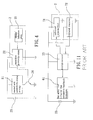
- FIG. 4 is a circuit block diagram of the non-contact sensor switch assembly in accordance with the present invention.
- FIG. 7 is a schematic side view illustrating the sensing operation of the proximity sensor unit upon approach of a user hand.
- FIG. 7A is a schematic applied view of the present invention, illustrating the proximity sensor unit installed in the back side of the sliding door panel of the automatic door and induced upon approach of a user hand.
- FIG. 9 is a schematic elevational view of a conventional automatic water tap.
- FIG. 10 is a schematic drawing illustrating the sensing operation of the infrared transmitter/receiver unit of the conventional automatic water tap.
- FIG. 11 is a circuit block diagram of the control circuit of the infrared transmitter receiver unit of the conventional automatic water tap.
- the proximity sensor unit 2 comprises an induction plate (or induction coil) 21 , a capacitive proximity sensor 22 , and a battery set 23 .
- the charge induction plate 21 is mounted in the casing of the self-contained apparatus 1 and electrically coupled with the capacitive proximity sensor 22 and the battery set 23 .
- the switching transistor 24 is electrically coupled to the proximity sensor unit 2 .
- FIG. 6 illustrates the non-contact sensor switch assembly used in an automatic door 5 in accordance with the present invention.
- the non-contact sensor switch assembly is installed in the casing 51 of the signal transmitter 52 of the control unit at the sliding door panel of the automatic door 5 .
- the charge induction plate 21 is immediately induced by a trace amount of electric charge from the hands of the user, the output of the capacitive proximity sensor 22 is changed from Low to High, thereby triggering the switching transistor 24 to switch on the power supply of the signal transmitter 52 of the control unit (i.e., to wake up the control unit).
- the control unit controls the automatic door 5 to open the sliding door panel.
- the capacitive proximity sensor 22 When the user moves the hands 3 out of the sensing range of the charge induction plate 21 , the capacitive proximity sensor 22 is changed from High to Low, thus, the switching transistor 24 switches off the power supply from the signal transmitter 52 of the control unit of the automatic door 5 , and therefore the control unit controls the automatic door 5 to close the sliding door panel and then returns to sleep mode (see also FIG. 7 ). Further, the switching transistor 24 and the proximity sensor unit 2 can also be installed in the back side of the glass sliding panel of an automatic door (see FIG. 7A ), achieving the same effects.
Landscapes
- Domestic Plumbing Installations (AREA)
Abstract
A non-contact sensor switch assembly includes a switching transistor adapted for switching on/off the supply of a power supply to the control unit of an automatic handwash dispenser, automatic water tap or automatic door, a charge induction plate inducible by an approaching body part of a person, and a capacitive proximity sensor electrically coupled between the charge induction plate and the switching transistor for triggering the switching transistor to switch on the supply of the power supply to the control unit of the automatic handwash dispenser, automatic water tap or automatic door upon approach of a body part of a person.
Description
1. Field of the Invention
The present invention relates to a self-contained apparatus and more particularly, to a non-contact sensor switch assembly for use in a self-contained apparatus, automatic water tap or automatic door, which automatically switches on (wakes up) the control unit of the self-contained apparatus, automatic water tap or automatic door upon approaching of a body part of a person, or switches off the control unit when the body part of the person is moved out of its effective sensing range.
2. Description of the Related Art
H1N1 new-type influenza, enteroviruses and many other virus variants cause increased infections. In the season when epidemics happen frequently, it is difficult to prohibit spread of infections. The best way to prohibit spread of infections is to wear a mouth mask in public places, to wash the hands frequently, and to avoid using public utilities. To avoid contamination, may public places provide self-contained apparatuses, such as automatic handwash dispenser, automatic sterilizing fluid dispenser, automatic induction water tap and etc. to serve people.
A conventional automatic handwash dispenser 6 or automatic water tap 8 generally use an infrared transmitter/receiver unit 7 for automatic operation control (see FIGS. 8˜11 ). The infrared transmitter/receiver unit 7 consists of an infrared transmitter 71 and an infrared receiver 72 for sensing the approaching of the hands of a user, and electrically coupled to a microprocessor 73 that controls the motor (or relay) 61 of the automatic handwash dispenser 6 or automatic water tap 8 to dispense an anti-bacterial handwash or to discharge water subject to the sensing control of the infrared transmitter/receiver unit 7. When the user moves the hands out of the sensing range of the infrared transmitter/receiver unit 7, the microprocessor 73 switches off the motor (or relay) 61 of the automatic handwash dispenser 6 or automatic water tap 8, stopping the supply of the anti-bacterial handwash or water.
The aforesaid prior art design has drawbacks as follows:
- 1. The infrared transmitter/
receiver unit 7 is constantly at the transmitting and receiving status for sensing the approaching of a body part of a person when electrically connected, wasting much power supply and being easy to fail. - 2. The infrared transmitter/
receiver unit 7 has a narrow sensing range. A user may be not put the hands accurately in the sensing range of the infrared transmitter/receiver unit 7, causing theautomatic handwash dispenser 6 orautomatic water tap 8 unable to dispense the anti-bacterial handwash or to discharge water accurately. - 3. The light of the sun may interfere with the functioning of the infrared transmitter/
receiver unit 7, and therefore the application of theautomatic handwash dispenser 6 orautomatic water tap 8 is limited.
The present invention has been accomplished under the circumstances in view. It is one object of the present invention to provide a non-contact sensor switch assembly, which is practical for use in a self-contained apparatus, automatic water tap or automatic door for automatically controlling the operation of the control unit of the self-contained apparatus, automatic water tap or automatic door, saving power consumption and achieving environmentally friendly performance.
To achieve this and other objects of the present invention, a self-contained apparatus comprises a control unit for operation control, and a non-contact sensor switch assembly electrically coupled to the control unit for switching on/off the supply of a power supply to the control unit. The non-contact sensor switch assembly comprises a switching transistor adapted for switching on/off the supply of the power supply to the control unit, and a proximity sensor unit, which comprises charge induction plate inducible by an approaching body part of a person, and a capacitive proximity sensor electrically coupled between the charge induction plate and the switching transistor. The capacitive proximity sensor is changed from Low to High to trigger the switching transistor in switching on the supply of the power supply to the control unit when the charge induction plate is induced by an approaching body part of a person, or changed from High to Low to electrically disconnect the switching transistor when the approaching body part of the person is moved out of the sensing range of the charge induction plate.
To achieve this and other objects of the present invention, an automatic door comprises a control unit, which comprises a signal transmitter unit installed in a sliding door panel and is adapted for controlling opening and closing of the sliding door panel, and a non-contact sensor switch assembly installed in the signal transmitter unit and electrically coupled to a signal transmitter of the signal transmitter unit for switching on/off the supply of a power supply to the signal transmitter. The non-contact sensor switch assembly comprises a switching transistor adapted for switching on/off the supply of the power supply to the signal transmitter, and a proximity sensor unit, which comprises charge induction plate inducible by an approaching body part of a person, and a capacitive proximity sensor electrically coupled between the charge induction plate and the switching transistor. The capacitive proximity sensor is changed from Low to High to trigger the switching transistor in switching on the supply of the power supply to the signal transmitter when the charge induction plate is induced by an approaching body part of a person, or changed from High to Low to electrically disconnect the switching transistor when the approaching body part of the person is moved out of the sensing range of the charge induction plate.
Referring to FIGS. 1˜4 , a non-contact sensor switch assembly is shown installed in a self-contained apparatus 1, for example, anti-bacterial handwash dispenser, comprising a switching transistor 24 and a proximity sensor unit 2.
The proximity sensor unit 2 comprises an induction plate (or induction coil) 21, a capacitive proximity sensor 22, and a battery set 23. The charge induction plate 21 is mounted in the casing of the self-contained apparatus 1 and electrically coupled with the capacitive proximity sensor 22 and the battery set 23. The switching transistor 24 is electrically coupled to the proximity sensor unit 2. When the charge induction plate 21 is induced by a trace amount of electric charge from the hand of a person approaching to the self-contained apparatus 1, the output of the capacitive proximity sensor 22 is changed from Low to High, thereby triggering the switching transistor 24 to switch on the power supply of the control unit (i.e., to wake up the control unit) of the self-contained apparatus 1. Thus, the control unit controls the motor or relay 11 of the self-contained apparatus 1 to dispense anti-bacterial handwash or sterilizing fluid. When the hand 3 is moved out of the sensing range of the charge induction plate 21, the capacitive proximity sensor 22 is changed from High to Low, thus, the switching transistor 24 switches off the power supply from the control unit of the self-contained apparatus 1, and therefore the control unit of the self-contained apparatus 1 returns to sleep mode. Subject to the application of the non-contact system of the present invention, the self-contained apparatus 1 saves power consumption, achieving eco-friendly performance.
Although particular embodiment of the invention have been described in detail for purposes of illustration, various modifications and enhancements may be made without departing from the spirit and scope of the invention. Accordingly, the invention is not to be limited except as by the appended claims.
Claims (4)
1. A self-contained apparatus comprising:
a control unit for operation control,
a non-contact sensor switch assembly electrically coupled to said control unit for switching on/off a power supply for said control unit, the non-contact sensor switch assembly comprising:
a switching transistor for switching on/off said power supply to said control unit, and
a proximity sensor unit, said proximity sensor unit comprising:
a charge induction portion inducible by an approaching body part of a person, and
a capacitive proximity sensor portion electrically coupled between said charge induction portion and said switching transistor, said capacitive proximity sensor being thereby actuated to trigger said switching transistor to switch on the supply of said power supply to said control unit responsive to a change of inductive-capacitive coupling between said charge induction and capacitive proximity sensor portions being induced by an approaching body part of a person, said capacitive proximity sensor being actuated to unswitch said switching transistor when the approaching body part of the person is moved out of the sensing range of said charge induction portion.
2. The self-contained apparatus as claimed in claim 1 , which is an anti-bacterial handwash dispenser.
3. The self-contained apparatus as claimed in claim 1 , which is an automatic water tap.
4. The self-contained apparatus as claimed in claim 1 , wherein said charge induction portion includes an induction coil.
Priority Applications (1)
| Application Number | Priority Date | Filing Date | Title |
|---|---|---|---|
| US13/236,921 US8754550B2 (en) | 2011-09-20 | 2011-09-20 | Self-contained apparatus/automatic door having a non-contact sensor switch assembly |
Applications Claiming Priority (1)
| Application Number | Priority Date | Filing Date | Title |
|---|---|---|---|
| US13/236,921 US8754550B2 (en) | 2011-09-20 | 2011-09-20 | Self-contained apparatus/automatic door having a non-contact sensor switch assembly |
Publications (2)
| Publication Number | Publication Date |
|---|---|
| US20130067816A1 US20130067816A1 (en) | 2013-03-21 |
| US8754550B2 true US8754550B2 (en) | 2014-06-17 |
Family
ID=47879290
Family Applications (1)
| Application Number | Title | Priority Date | Filing Date |
|---|---|---|---|
| US13/236,921 Expired - Fee Related US8754550B2 (en) | 2011-09-20 | 2011-09-20 | Self-contained apparatus/automatic door having a non-contact sensor switch assembly |
Country Status (1)
| Country | Link |
|---|---|
| US (1) | US8754550B2 (en) |
Cited By (1)
| Publication number | Priority date | Publication date | Assignee | Title |
|---|---|---|---|---|
| CN109681078A (en) * | 2018-12-27 | 2019-04-26 | 安徽大学 | Chemical reagent storage cabinet induction type intelligence shutdown method and chemical reagent storage cabinet |
Families Citing this family (8)
| Publication number | Priority date | Publication date | Assignee | Title |
|---|---|---|---|---|
| US9098140B2 (en) * | 2013-05-02 | 2015-08-04 | Paragon Technologies Co., Ltd. | Power-saving touch pad apparatus |
| DE102013008747A1 (en) * | 2013-05-23 | 2014-11-27 | Brose Fahrzeugteile Gmbh & Co. Kommanditgesellschaft, Hallstadt | Adjustment method for adjusting an adjustable by means of a servomotor vehicle window and control system for such a vehicle window |
| WO2015074274A1 (en) * | 2013-11-25 | 2015-05-28 | Reckitt Benckiser (Brands) Limited | A base unit for a liquid dispenser and a method of operating the base unit |
| DE102014117896A1 (en) * | 2014-12-04 | 2016-06-23 | Brose Fahrzeugteile Gmbh & Co. Kg, Hallstadt | Method for controlling a sliding door arrangement of a motor vehicle |
| US10665084B1 (en) * | 2017-04-26 | 2020-05-26 | Swipesense, Inc. | Retrofit compliance apparatus and compliance system for hand hygiene dispensers |
| CN114992716B (en) * | 2018-03-07 | 2024-04-05 | Lg电子株式会社 | Air conditioning equipment |
| JP7230999B1 (en) | 2021-12-02 | 2023-03-01 | 横浜ゴム株式会社 | Airplane lavatory unit door opening/closing mechanism |
| JP7231000B1 (en) | 2021-12-02 | 2023-03-01 | 横浜ゴム株式会社 | Airplane lavatory unit door opening/closing mechanism |
Citations (4)
| Publication number | Priority date | Publication date | Assignee | Title |
|---|---|---|---|---|
| DE3938533A1 (en) * | 1989-11-21 | 1991-05-23 | Rainer M Lutz | Hand-rinsing water tap with sequential automatic control - responds to proximity of hands with timed spray of cleansing agent between outflows of warm water |
| WO1994000645A1 (en) * | 1992-06-18 | 1994-01-06 | Harald Philipp | Hands-free water flow control apparatus and method |
| WO2009075858A1 (en) * | 2007-12-11 | 2009-06-18 | Masco Corporation Of Indiana | Capacitive coupling arrangement for a faucet |
| US7635969B2 (en) * | 2004-11-04 | 2009-12-22 | Rohm Co., Ltd. | Power supply unit and portable device |
-
2011
- 2011-09-20 US US13/236,921 patent/US8754550B2/en not_active Expired - Fee Related
Patent Citations (4)
| Publication number | Priority date | Publication date | Assignee | Title |
|---|---|---|---|---|
| DE3938533A1 (en) * | 1989-11-21 | 1991-05-23 | Rainer M Lutz | Hand-rinsing water tap with sequential automatic control - responds to proximity of hands with timed spray of cleansing agent between outflows of warm water |
| WO1994000645A1 (en) * | 1992-06-18 | 1994-01-06 | Harald Philipp | Hands-free water flow control apparatus and method |
| US7635969B2 (en) * | 2004-11-04 | 2009-12-22 | Rohm Co., Ltd. | Power supply unit and portable device |
| WO2009075858A1 (en) * | 2007-12-11 | 2009-06-18 | Masco Corporation Of Indiana | Capacitive coupling arrangement for a faucet |
Cited By (1)
| Publication number | Priority date | Publication date | Assignee | Title |
|---|---|---|---|---|
| CN109681078A (en) * | 2018-12-27 | 2019-04-26 | 安徽大学 | Chemical reagent storage cabinet induction type intelligence shutdown method and chemical reagent storage cabinet |
Also Published As
| Publication number | Publication date |
|---|---|
| US20130067816A1 (en) | 2013-03-21 |
Similar Documents
| Publication | Publication Date | Title |
|---|---|---|
| US8754550B2 (en) | Self-contained apparatus/automatic door having a non-contact sensor switch assembly | |
| US20170107704A1 (en) | Integrally formed sensor type faucet liquid soap dispenser | |
| TW200829819A (en) | On demand electronic faucet | |
| US20120206269A1 (en) | Electronic System to Signal Proximity of an Object | |
| ES2177685T3 (en) | CONTROL DEVICE FOR SANITARY FAUCET. | |
| CA2895477A1 (en) | Touchless activation of a toilet | |
| CN104089065B (en) | Contact control formula effluent control device and its control method | |
| WO2006102316A3 (en) | Diagnostic circuit | |
| JP6735041B2 (en) | Toilet system | |
| US9279239B2 (en) | Manual and automatic integrated faucet | |
| US20160032571A1 (en) | Piezoelectric Touch-Controlled Faucet | |
| CN202387013U (en) | Ultraviolet lamp control device for wardrobe | |
| US20160168835A9 (en) | Touchless Activation of a Toilet | |
| US20150022025A1 (en) | Smart energy-saving power source control apparatus and method | |
| KR101291151B1 (en) | The low power consumption concent for blocking the standby power using ir signal | |
| CN202206357U (en) | Non-contact induction device for self-contained equipment | |
| CN206672334U (en) | A kind of safety convenience instrument | |
| JP6704610B2 (en) | Toilet system | |
| KR102164446B1 (en) | Control method of sensor light using for 2 pass PIR | |
| KR101572006B1 (en) | Water supply system includes a portable detector comprising a malfunction prevention function | |
| KR20160051562A (en) | A water supply valve opening and closing control apparatus according to a non-contact manner | |
| CN201698323U (en) | Computer with display control function | |
| WO2008059094A2 (en) | Hands-free device for controlling the flow of water from a tap | |
| CN219959626U (en) | Socket with infrared remote control function and infrared remote controller | |
| CN213637506U (en) | Voltage switching circuit for user interface |
Legal Events
| Date | Code | Title | Description |
|---|---|---|---|
| FEPP | Fee payment procedure |
Free format text: MAINTENANCE FEE REMINDER MAILED (ORIGINAL EVENT CODE: REM.) |
|
| LAPS | Lapse for failure to pay maintenance fees |
Free format text: PATENT EXPIRED FOR FAILURE TO PAY MAINTENANCE FEES (ORIGINAL EVENT CODE: EXP.) |
|
| STCH | Information on status: patent discontinuation |
Free format text: PATENT EXPIRED DUE TO NONPAYMENT OF MAINTENANCE FEES UNDER 37 CFR 1.362 |
|
| FP | Lapsed due to failure to pay maintenance fee |
Effective date: 20180617 |
|
| FP | Lapsed due to failure to pay maintenance fee |
Effective date: 20180617 |