US8724561B2 - Apparatus and method for resource allocation information transmission in mobile communication system - Google Patents
Apparatus and method for resource allocation information transmission in mobile communication system Download PDFInfo
- Publication number
- US8724561B2 US8724561B2 US12/797,843 US79784310A US8724561B2 US 8724561 B2 US8724561 B2 US 8724561B2 US 79784310 A US79784310 A US 79784310A US 8724561 B2 US8724561 B2 US 8724561B2
- Authority
- US
- United States
- Prior art keywords
- resource allocation
- allocation information
- frequency band
- search space
- anchor
- Prior art date
- Legal status (The legal status is an assumption and is not a legal conclusion. Google has not performed a legal analysis and makes no representation as to the accuracy of the status listed.)
- Active, expires
Links
Images


Classifications
-
- H—ELECTRICITY
- H04—ELECTRIC COMMUNICATION TECHNIQUE
- H04L—TRANSMISSION OF DIGITAL INFORMATION, e.g. TELEGRAPHIC COMMUNICATION
- H04L1/00—Arrangements for detecting or preventing errors in the information received
- H04L1/0001—Systems modifying transmission characteristics according to link quality, e.g. power backoff
- H04L1/0036—Systems modifying transmission characteristics according to link quality, e.g. power backoff arrangements specific to the receiver
- H04L1/0038—Blind format detection
-
- H—ELECTRICITY
- H04—ELECTRIC COMMUNICATION TECHNIQUE
- H04W—WIRELESS COMMUNICATION NETWORKS
- H04W72/00—Local resource management
- H04W72/20—Control channels or signalling for resource management
-
- H—ELECTRICITY
- H04—ELECTRIC COMMUNICATION TECHNIQUE
- H04L—TRANSMISSION OF DIGITAL INFORMATION, e.g. TELEGRAPHIC COMMUNICATION
- H04L1/00—Arrangements for detecting or preventing errors in the information received
- H04L1/0001—Systems modifying transmission characteristics according to link quality, e.g. power backoff
- H04L1/0009—Systems modifying transmission characteristics according to link quality, e.g. power backoff by adapting the channel coding
- H04L1/001—Systems modifying transmission characteristics according to link quality, e.g. power backoff by adapting the channel coding applied to control information
-
- H—ELECTRICITY
- H04—ELECTRIC COMMUNICATION TECHNIQUE
- H04L—TRANSMISSION OF DIGITAL INFORMATION, e.g. TELEGRAPHIC COMMUNICATION
- H04L1/00—Arrangements for detecting or preventing errors in the information received
- H04L1/12—Arrangements for detecting or preventing errors in the information received by using return channel
- H04L1/16—Arrangements for detecting or preventing errors in the information received by using return channel in which the return channel carries supervisory signals, e.g. repetition request signals
- H04L1/18—Automatic repetition systems, e.g. Van Duuren systems
- H04L1/1812—Hybrid protocols; Hybrid automatic repeat request [HARQ]
- H04L1/1816—Hybrid protocols; Hybrid automatic repeat request [HARQ] with retransmission of the same, encoded, message
-
- H—ELECTRICITY
- H04—ELECTRIC COMMUNICATION TECHNIQUE
- H04L—TRANSMISSION OF DIGITAL INFORMATION, e.g. TELEGRAPHIC COMMUNICATION
- H04L1/00—Arrangements for detecting or preventing errors in the information received
- H04L1/12—Arrangements for detecting or preventing errors in the information received by using return channel
- H04L1/16—Arrangements for detecting or preventing errors in the information received by using return channel in which the return channel carries supervisory signals, e.g. repetition request signals
- H04L1/18—Automatic repetition systems, e.g. Van Duuren systems
- H04L1/1829—Arrangements specially adapted for the receiver end
- H04L1/1854—Scheduling and prioritising arrangements
-
- H—ELECTRICITY
- H04—ELECTRIC COMMUNICATION TECHNIQUE
- H04L—TRANSMISSION OF DIGITAL INFORMATION, e.g. TELEGRAPHIC COMMUNICATION
- H04L27/00—Modulated-carrier systems
- H04L27/26—Systems using multi-frequency codes
- H04L27/2601—Multicarrier modulation systems
-
- H—ELECTRICITY
- H04—ELECTRIC COMMUNICATION TECHNIQUE
- H04L—TRANSMISSION OF DIGITAL INFORMATION, e.g. TELEGRAPHIC COMMUNICATION
- H04L5/00—Arrangements affording multiple use of the transmission path
- H04L5/003—Arrangements for allocating sub-channels of the transmission path
- H04L5/0037—Inter-user or inter-terminal allocation
-
- H—ELECTRICITY
- H04—ELECTRIC COMMUNICATION TECHNIQUE
- H04L—TRANSMISSION OF DIGITAL INFORMATION, e.g. TELEGRAPHIC COMMUNICATION
- H04L5/00—Arrangements affording multiple use of the transmission path
- H04L5/003—Arrangements for allocating sub-channels of the transmission path
- H04L5/0044—Arrangements for allocating sub-channels of the transmission path allocation of payload
-
- H—ELECTRICITY
- H04—ELECTRIC COMMUNICATION TECHNIQUE
- H04L—TRANSMISSION OF DIGITAL INFORMATION, e.g. TELEGRAPHIC COMMUNICATION
- H04L5/00—Arrangements affording multiple use of the transmission path
- H04L5/003—Arrangements for allocating sub-channels of the transmission path
- H04L5/0053—Allocation of signaling, i.e. of overhead other than pilot signals
-
- H—ELECTRICITY
- H04—ELECTRIC COMMUNICATION TECHNIQUE
- H04W—WIRELESS COMMUNICATION NETWORKS
- H04W72/00—Local resource management
- H04W72/04—Wireless resource allocation
Definitions
- the present invention relates to an apparatus and a method for transmitting resource allocation information. More particularly, the present invention relates to a carrier aggregation system in which a user equipment can simultaneously transmit and receive data using a plurality Component Carriers (CCs).
- CCs Component Carriers
- each carrier constituting the plurality of carriers usable by the user equipment is referred to as a Component Carrier (CC).
- a CC is also called a fundamental unit of an operable frequency band of the system, that is, a Frequency Assignment (FA).
- FA Frequency Assignment
- the user equipment which transmits and receives data using the multiple carriers at the same time, needs to detect resource allocation information of the carriers together.
- An aspect of the present invention is to address at least the above-mentioned problems and/or disadvantages and to provide at least the advantages described below. Accordingly, an aspect of the present invention is to provide an apparatus and a method for transmitting resource allocation information in a mobile communication system.
- Another aspect of the present invention is to provide an apparatus and a method for transmitting resource allocation information of low blind decoding complexity in a mobile communication system.
- Yet another aspect of the present invention is to provide an apparatus and a method for allowing Hybrid Automatic Repeat reQuest (HARQ) retransmission of a non-anchor CC alone and simultaneously maintaining low blind decoding complexity.
- HARQ Hybrid Automatic Repeat reQuest
- a method for receiving resource allocation information in a mobile communication system includes determining a search space for use in a second frequency band using resource allocation information of a first process detected in a first frequency band, detecting resource allocation information using the search space in the second frequency band, and when failing to decode received data according to the resource allocation information detected in the second frequency band, re-detecting resource allocation information of the first process in the second frequency in a first time interval using the search space without detecting the resource allocation information of the first process in the first frequency band.
- an apparatus for receiving resource allocation information in a mobile communication system includes a controller for determining a search space for use in a second frequency band using resource allocation information of a first process detected in a first frequency band, for detecting resource allocation information using the search space in the second frequency band, and, when failing to decode received data according to the resource allocation information detected in the second frequency band, for re-detecting resource allocation information of the first process in the second frequency in a first time interval using the search space without detecting the resource allocation information of the first process in the first frequency band.
- a method for transmitting resource allocation information in a mobile communication system includes, when generating resource allocation information for retransmission, generating the resource allocation information such that a resource for the retransmission is not included in a first frequency band and is included only in a second frequency band, determining a transmission resource using the resource allocation information, and transmitting the resource allocation information to a receiver over the transmission resource.
- an apparatus for transmitting resource allocation information in a mobile communication system includes a controller for, when generating resource allocation information for retransmission, generating the resource allocation information such that a resource for the retransmission is not included in a first frequency band and is included only in a second frequency band, and for determining a transmission resource using the resource allocation information, and a transmitter for transmitting the resource allocation information to a receiver over the transmission resource.
- FIG. 1 illustrates a carrier aggregation system according to an exemplary embodiment of the present invention
- FIG. 2 illustrates a resource allocation transmission process using a dummy Physical Downlink Data CHannel (PDCCH) according to an exemplary embodiment of the present invention
- FIG. 3 illustrates a resource allocation information searching process using synchronous Hybrid Automatic Repeat reQuest (HARQ) in a downlink according to an exemplary embodiment of the present invention
- FIG. 4 illustrates a time interval setting method for searching the resource allocation information using asynchronous HARQ in the downlink according to an exemplary embodiment of the present invention
- FIG. 5 illustrates a search time interval setting method with a plurality of HARQ processes according to an exemplary embodiment of the present invention
- FIG. 6 illustrates a resource allocation information search region setting method of a User Equipment (UE) with one HARQ process according to an exemplary embodiment of the present invention
- FIG. 7 illustrates a resource allocation information search region setting method of a UE with a plurality of HARQ processes according to an exemplary embodiment of the present invention
- FIG. 8 illustrates a resource allocation information search region setting method of a UE with a plurality of HARQ processes when new resource allocation information is found according to an exemplary embodiment of the present invention
- FIG. 9 illustrates a resource allocation information searching process using synchronous HARQ in an uplink according to an exemplary embodiment of the present invention
- FIG. 10 illustrates a resource allocation information detecting process of a UE according to an exemplary embodiment of the present invention
- FIG. 11 illustrates a resource allocation information detecting process of a UE according to an exemplary embodiment of the present invention
- FIG. 12 illustrates a search space setting method with a plurality of HARQ processes according to an exemplary embodiment of the present invention
- FIG. 13 is a block diagram of a UE according to an exemplary embodiment of the present invention.
- FIG. 14 illustrates operations of an eNode B according to an exemplary embodiment of the present invention.
- FIG. 15 is a block diagram of an eNode B according to an exemplary embodiment of the present invention.
- Exemplary embodiments of the present invention provide an apparatus and a method for transmitting resource allocation information in a mobile communication system.
- a User Equipment In a carrier aggregation system, a User Equipment (UE) simultaneously transmits and receives data using a plurality of Component Carriers (CCs) and thus needs to detect resource allocation information of the CCs together.
- UE User Equipment
- CCs Component Carriers
- the carrier aggregation system is newly adopted by the Institute of Electrical and Electronics Engineers (IEEE) 802.16m and the 3rd Generation Partnership Project (3GPP) Long Term Evolution (LTE)-Advanced and its standardization is under way.
- the carrier aggregation system is also called a multi-carrier system, a multi-Frequency Assignment (FA) system, and a frequency overlay system.
- the bandwidth of the CC for example, can be determined as the bandwidth of the IEEE 802.16 and the LTE system.
- FIG. 1 illustrates a carrier aggregation system according to an exemplary embodiment of the present invention.
- an eNode B 100 transmits and receives data using a plurality of CCs.
- UEs 110 , 120 and 130 can differently set the number and the range of the CCs to transmit and receive, based on their capability.
- blind decoding is used by the UE to obtain its corresponding resource allocation information in the allocated resource, that is, in the CC. Rather than directly obtaining the resource allocation information from separate control information, blind decoding allows only a particular UE to succeed in decoding according to a preset rule. In general, blind decoding does not include a UE Identifier (ID) in the resource allocation information.
- ID UE Identifier
- the eNode B transmits the resource allocation information by scrambling or masking the UE ID with all or part of the resource allocation information including a Cyclic Redundancy Check (CRC), and the UE can obtain the resource allocation information by descrambling or demasking it using its own ID.
- CRC Cyclic Redundancy Check
- blind decoding assists in maintaining a small message size of the resource allocation information by not explicitly sending the UE ID.
- Blind decoding is expected to be used in both the IEEE 802.16m system and the LTE-Advanced system.
- a method for encoding the resource allocation information of the CC per CC and transmitting the resource allocation information over different physical channels is provided.
- the physical channel carrying the resource allocation information can be referred to as a Physical Downlink Control CHannel (PDCCH).
- the PDCCH is separately given per CC and the resource allocation information of each CC can be transmitted over each PDCCH.
- carrier aggregation it is necessary to obtain the resource allocation information of each CC by detecting each CC. As a result, when the resource allocation information is blind-decoded and transmitted, the complexity is increased.
- the UE can select its anchor CC from the plurality of CCs, and preferentially detect the resource allocation information in the anchor CC.
- the UE searches the resource allocation information in its selected anchor CC, and searches the resource allocation information of non-anchor CCs only when detecting the resource allocation information.
- a method for setting the anchor CC and non-anchor CC setting provided.
- the eNode B selects one or more CCs, from the plurality of the operating CCs, as the CCs for use by the UE.
- the CCs used by the UEs can differ from each other. For example, when the eNode B operates five CCs ⁇ CC1, CC2, CC3, CC4, CC5 ⁇ , the CCs for use by the first UE can be set to ⁇ CC1, CC2, CC3 ⁇ and the CCs for use by the second UE can be set to ⁇ CC3, CC4, CC5 ⁇ .
- the eNode B selects one or more CCs from the CCs for use by the UE as the anchor CC of the corresponding UE.
- the anchor CC of the first UE can be set to CC1 and the anchor CC of the second UE can be set to CC3.
- the other CCs excluding the anchor CC among the CCs used by the UE become the non-anchor CCs.
- the non-anchor CCs of the first UE are ⁇ CC2, CC3 ⁇
- the non-anchor CCs of the second UE are ⁇ CC4, CC5 ⁇ .
- the anchor and non-anchor CC setting can be carried out during an initial access of the UE, a handover, an eNode B request, a UE request, a radio resource configuration, and the like.
- the UE searches the resource allocation information in the anchor CC and searches the resource allocation information of the other CCs (the non-anchor CCs) only when detecting the resource allocation information in the anchor CC
- a method for detecting the resource allocation information when there is no resource allocation information in the anchor CC and the resource allocation information is transmitted only in the non-anchor CC is required.
- HARQ Hybrid Auto Repeat reQuest
- the HARQ retransmission using only the non-anchor CC can take place but may require a complex operation and thus render it infeasible.
- an exemplary method for limiting a search condition and a search range of the resource allocation information of the non-anchor CC.
- This method restricts the PDCCH search range in the non-anchor CC according to resource size and location corresponding to the PDCCH detected in the anchor CC.
- the number of PDCCH decoding times in the anchor CC is limited to 44 and the number of PDCCH decoding times in the non-anchor CC is limited to n (1 ⁇ n ⁇ 44), thus lowering the overall complexity in the blind decoding.
- FIG. 2 illustrates a resource allocation transmission process using a dummy PDCCH according to an exemplary embodiment of the present invention.
- the UE only upon detecting the dummy PDCCH in the anchor CC can the UE obtain the corresponding resource allocation information in the non-anchor CC in step 210 . This implies that the UE obtains the resource allocation information in the non-anchor CC by adding the dummy PDCCH to the anchor CC.
- the eNode B can be the transmitter and the UE can be the receiver. However, depending on the object that transmits data, the UE may be the transmitter and the eNode B can be the receiver.
- the UE When detecting the resource allocation information in the anchor CC, the UE searches the resource allocation information in subframes of the non-anchor CC of the same time. Also, if the resource allocation information is not detected in the anchor CC, the UE searches the resource allocation information in the subframes of the non-anchor CC predicted to contain the resource allocation information for the HARQ retransmission.
- the predicted time interval of the resource allocation information for the HARQ retransmission becomes one subframe defined by a HARQ retransmission period.
- the UE searches the resource allocation information of the non-anchor CC in the one defined subframe.
- FIG. 3 illustrates a resource allocation information searching process using synchronous HARQ in the downlink according to an exemplary embodiment of the present invention.
- the synchronous HARQ is set to conduct the HARQ retransmission after seven subframes.
- the UE detects the PDCCH in the anchor CC that is, when the UE detects the resource allocation information but fails to detect the PDCCH 310 in the non-anchor CC
- FIG. 4 illustrates a time interval setting method for searching the resource allocation information using asynchronous HARQ in the downlink according to an exemplary embodiment of the present invention.
- a subframe time interval for searching the resource allocation information can be determined as follows.
- the UE when the UE fails to detect data 410 in a random HARQ process, it sends Negative ACKnowledgement (NACK) feedback.
- NACK Negative ACKnowledgement
- the UE sets a HARQ retransmission prediction subframe interval 420 after two subframes based on the subframe transmitting the NACK feedback and searches resource allocation information in this interval 420 .
- the resource allocation information search time interval ends in the subframe of success.
- the search time interval spans the next N subframes after the previous transmission.
- FIG. 5 illustrates a search time interval setting method for a plurality of HARQ processes according to an exemplary embodiment of the present invention.
- retransmission can occur in each HARQ process and the time interval predicted for retransmission in the non-anchor CC can differ per HARQ process.
- the resource allocation information search time intervals corresponding to the HARQ processes are set to 6 subframes 520 and 5 subframes 560 respectively, such that three subframes overlap.
- the search time interval is set to 8 subframes 590 which is the union of the two time intervals.
- the UE waits to detect the resource allocation information in subframes 525 and 565 as the failed resource allocation information of subframes 515 and 555 .
- FIG. 6 illustrates a resource allocation information search region setting method of a UE with one HARQ process according to an exemplary embodiment of the present invention.
- the UE when detecting resource allocation information in subframe 610 of the anchor CC but failing to detect resource allocation information in subframe 615 of the non-anchor CC, the UE generates and sends NACK to the eNode B. After two subframes following NACK transmission, the UE searches in a search time interval 620 to detect retransmission of the failed resource allocation information of subframe 615 of the non-anchor CC.
- the search space is the same as in the initial resource allocation information search or the retransmitted resource allocation information search.
- FIG. 7 illustrates a resource allocation information search region setting method of a UE with a plurality of HARQ processes according to an exemplary embodiment of the present invention.
- the UE when detecting resource allocation information in subframes 710 and 750 of the anchor CC but failing to detect resource allocation information in subframes 715 and 755 of the non-anchor CC, the UE sends NACK to the appropriate eNode Bs.
- the UE searches in a search time interval 720 to detect retransmission of the failed resource allocation information of subframe 715 in the non-anchor CC.
- the search space is the same as in the initial resource allocation information search or the retransmitted resource allocation information search.
- the UE searches in a search time interval 760 to detect the retransmission of the failed resource allocation information of subframe 765 in the non-anchor CC.
- the search space is the same as in the initial resource allocation information search or the retransmitted resource allocation information search.
- the later corresponding search space 760 is used for the search in the overlapped search time interval. That is, when the search time intervals of the resource allocation information of subframes 715 and 755 overlap, the search space 760 of the resource allocation information of subframe 765 is applied to the search.
- the resource allocation information 725 indicates ACK feedback of the transmit resource.
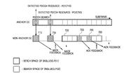
- FIG. 8 illustrates a resource allocation information search region setting method of a UE with a plurality of HARQ processes when new resource allocation information is found according to an exemplary embodiment of the present invention.
- the UE when detecting resource allocation information in subframes 810 and 850 of the anchor CC but failing to detect resource allocation information in subframes 815 and 835 of the non-anchor CC, the UE sends NACK to each appropriate eNode B.
- the UE searches in a search time interval 820 to detect the retransmission of the failed resource allocation information of subframe 815 of the non-anchor CC.
- the search space is the same as in the initial resource allocation information search or the retransmitted resource allocation information search.
- the UE searches in a search time interval 860 to detect retransmission of the failed resource allocation information of subframe 835 of the non-anchor CC.
- the search space is the same as in the initial resource allocation information search or the retransmitted resource allocation information search.
- a later corresponding search space is used for the search in the overlapped search time interval. That is, when the search time intervals of the resource allocation information 865 overlap, the search space corresponding to the resource allocation information 865 is applied to the search.
- the search space of the non-anchor CC for the resource allocation information of subframe 870 of the anchor CC is applied to the detection of resource allocation information of subframe 875 in the non-anchor CC.
- FIG. 9 illustrates a resource allocation information searching process using synchronous HARQ in an uplink according to an exemplary embodiment of the present invention.
- the eNode B and the UE are aware of when the retransmitted resource allocation information or the retransmit data is generated in the non-anchor CC.
- the subframe time interval carrying ACK/NACK information is the subframe region defined to deliver the resource allocation information.
- the resource allocation information is searched in the anchor CC and the non-anchor CC as well.
- the resource allocation information of subframe 915 is detected in the anchor CC of the downlink 910 of the UE, and the resource allocation information of subframe 920 is detected in the non-anchor CC.
- FIG. 10 illustrates a resource allocation information detecting process of a UE according to an exemplary embodiment of the present invention.
- step 1010 it is determined if the anchor and non-anchor CCs are set by signaling with the eNode B in step 1010 . If it is determined in step 1010 that the anchor and non-anchor CCs are set, the UE detects the resource allocation information in the anchor CC in step 1020 . On the other hand, if it is determined in step 1010 that the anchor and non-anchor CCs are not set, the UE sets the anchor and non-anchor CCs by signaling with the eNode B in step 1015 and detects the resource allocation information in the determined anchor CC in step 1020 .
- the signaling follows a procedure defined by the standard.
- step 1025 the UE determines if it is to detect resource allocation information in the non-anchor CC. If the UE determines in step 1025 that it is to detect resource allocation information in the non-anchor CC, the UE detects resource allocation information of the non-anchor CC in step 1030 and transmits and receives data according to the detected resource allocation information in step 1040 .
- the UE determines in step 1025 that it is not to detect resource allocation information in the non-anchor CC, the UE transmits and receives data according to the detected resource allocation information in step 1040 .
- the resource allocation information in step 1040 indicates the previously detected resource allocation information.
- the UE When detecting the resource allocation information in the anchor CC, the UE determines the resource allocation information search region of the non-anchor CC according to the resource size and location of the detected resource allocation information.
- the search region of the anchor CC is expressed as a function SA(k,m,UEID) and the search region of the non-anchor CC can be expressed as a function SN(k,m,UEID,SD).
- k denotes the subframe number
- m denotes the CC number
- UEID denotes the ID of the UE
- SD denotes the resource size and location of the resource allocation information detected in the anchor CC.
- the search region of the anchor CC is determined by the subframe number, the CC number, and the UE ID.
- the search region of the non-anchor CC is determined by the subframe number, the UE ID, and the resource location and size of the information detected in the anchor CC.
- the UE When detecting no resource allocation information in the anchor CC, the UE searches the resource allocation information in the non-anchor CC using the search region used in the past.
- the UE can select one of the HARQ processes predicted to deliver the retransmission in the current subframe of the non-anchor CC, and define the resource allocation information search region used in the previous transmission of the selected HARQ process as the search region of the current subframe.
- the resource allocation information search region of the non-anchor CC is expressed as SN(k,m,UEID,SD_mem), where k denotes the subframe number, UEID denotes the ID of the UE, and SD_mem is defined as follows. That is, when the resource allocation information search region in the non-anchor CC is set to SN(k,m,UEID,SD), the decoding of the received data fails, and the NACK is fed back, SD_mem after two subframes based on the NACK feedback subframe can be set to SD.
- FIG. 11 illustrates a resource allocation information detecting process of a UE according to an exemplary embodiment of the present invention.
- the UE initializes variables (N, k) used in the algorithm in step 1110 .
- the UE receives the next subframe; that is the subframe to process in step 1115 .
- N denotes the number of pending resource allocation information or data to retransmit
- k denotes the subframe number.
- the UE determines the PDCCH search space of the anchor CC in step 1120 and searches the PDCCH, that is, the resource allocation information in the determined search space in step 1125 .
- step 1130 the UE determines if the PDCCH is detected. Upon detecting the PDCCH, that is, upon detecting the resource allocation information in step 1130 , the UE receives data in the anchor CC using the resource allocation information in step 1140 .
- S denotes the standard of the search space to use in the current non-anchor CC
- S 2 denotes the standard of the search space used in the initial transmission of the resource allocation information to retransmit in the non-anchor CC. Namely, the standard of the search space to currently use is set to the standard of the search space previously used.
- the UE determines the PDCCH search space in the non-anchor CC using the search space standard S (S,UEID,k) in step 1160 , and searches the PDCCH of the non-anchor CC, that is, the resource allocation information in the determined search space in step 1165 .
- the search space standard setting and the search space setting conform to the procedures defined by the standard.
- step 1170 the UE determines if the PDCCH is detected in the non-anchor CC. If it is determined that the UE detects the PDCCH, that is, the resource allocation information in the non-anchor CC in step 1170 , the UE receives data from the non-anchor CC according to the resource allocation information in step 1175 .
- step 1180 determines in step 1180 that there is not a data reception failure of step 1175 is successfully received in step 1180 . If the UE determines in step 1185 if the successfully received data is a retransmission. If the UE determines in step 1185 that the successfully received data is retransmitted, the UE decreases the number of the pending resource allocation information or data to retransmit by one in step 1195 .
- the UE receives a next frame in step 1115 and then repeats the subsequent steps.
- the UE when receiving the resource allocation information in the anchor CC, the UE obtains parameters for determining the search space to use in the non-anchor CC from the resource allocation information, and determines the search space to use in the non-anchor CC using the determined parameters.
- the UE uses the determined search space to search the resource allocation information in the non-anchor CC. Upon detecting the resource allocation information, the UE receives data in the non-anchor CC according to the detected resource allocation information.
- the NACK feedback is generated, which is not illustrated.
- the UE determines whether the data is retransmitted in the corresponding subframe, determined using the search space used when the data reception fails in the non-anchor CC.
- the determined corresponding subframe can vary according to the synchronous HARQ or the asynchronous HARQ as stated earlier.
- FIG. 12 illustrates a search space setting method with a plurality of HARQ processes according to an exemplary embodiment of the present invention.
- step 1210 it is determined in step 1210 if the resource allocation information search time intervals of the non-anchor CC overlap each other.
- the search time corresponding to the later HARQ process is applied to the overlapping resource allocation information search time intervals in the non-anchor CC in step 1220 .
- the search space used in the recent HARQ process is applied to the overlapping subframe intervals.
- step 1210 if it is determined in step 1210 that the resource allocation information search time intervals of the non-anchor CC do not overlap each other, it is determined in step 1230 if a PDCCH of the newly detected anchor CC is present.
- a PDCCH of the newly detected anchor CC is present, that is, when new resource allocation information is detected in the anchor CC in step 1230 , the search space determined from the newly detected anchor CC is applied to the overlapping resource allocation information search time intervals of the non-anchor CC corresponding to the newly detected anchor CC in step 1240 .
- step 1240 the search space determined from the newly detected anchor CC is applied to the subframe overlapping the non-anchor CC corresponding to the newly detected anchor CC.
- FIG. 13 is a block diagram of a UE according to an exemplary embodiment of the present invention.
- the UE includes a transceiver duplexer 1310 , a receiver 1315 , a transmitter 1320 , a resource extractor and allocator 1330 , a resource allocation information detector 1340 , a demodulator and decoder 1345 , a modulator and encoder 1350 , a carrier aggregation setter 1360 , and a data buffer 1365 .
- the transceiver duplexer 1310 forwards a receive signal from an antenna to the receiver 1315 , and transmits a signal output from the transmitter 1320 over the antenna.
- the receiver 1315 converts a Radio Frequency (RF) signal output from the transceiver duplexer 1310 to an analog signal, converts the analog signal to sample data, and outputs the sample data to the resource extractor and allocator 1330 .
- RF Radio Frequency
- the transmitter 1320 converts the output data from the resource extractor and allocator 1330 to an analog signal, converts the analog signal to an RF signal, and outputs the RF signal to the transceiver duplexer 1310 .
- the resource extractor and allocator 1330 extracts the corresponding resource from the sample data output from the receiver 1315 according to its anchor CC and non-anchor CC, and outputs the extracted resource to the demodulator and decoder 1345 .
- the resource extractor and allocator 1330 includes the data output from the modulator and encoder 1350 with its anchor CC and non-anchor CC and outputs the data to the transmitter 1330 .
- the demodulator and decoder 1345 demodulates and decodes the output data from the resource extractor and allocator 1330 according to a defined demodulation and decoding scheme, and outputs the data to the data buffer 1365 by subframes.
- the modulator and encoder 1350 modulates and encodes the output data from the data buffer 1365 according to a defined modulation and encoding scheme, and outputs the data to the resource extractor and allocator 1330 .
- the data buffer 1365 stores the subframes output from the demodulator and decoder 1345 and outputs the stored data to the upper layer.
- the data buffer 1365 also stores data received from the upper layer and outputs the stored data to the modulator and encoder 1350 .
- the resource allocation information detector 1340 searches the resource allocation information in the anchor CC per subframe received, searches the resource allocation information of the non-anchor CC in the defined time interval, and outputs the results to the resource extractor and allocator 1330 .
- the time interval and the search region for the resource allocation information search of the non-anchor CC are determined by the resource allocation information detector 1340 according to the data transmission and reception result.
- the resource allocation information detected in the anchor and non-anchor CCs is forwarded to the resource extractor and allocator 1330 , and the data transmission and reception is performed using the corresponding resource.
- the carrier aggregation setter 1360 determines the anchor and non-anchor CCs by signaling with the eNode B.
- a controller which is not illustrated, can function as the resource allocation information detector 1340 and the carrier aggregation setter 1360 .
- the controller can process all or part of the functions of the resource allocation information detector 1340 and the carrier aggregation setter 1360 .
- FIG. 14 illustrates operations of an eNode B according to an exemplary embodiment of the present invention.
- the eNode B determines in step 1410 if the anchor and non-anchor CCs are set by signaling with the UE.
- the eNode B generates the resource allocation information for the corresponding UE in step 1420 and determines the transmit resource for carrying the resource allocation information in step 1425 .
- the signaling conforms to the procedure defined by the standard.
- the eNode B transmits the resource allocation information to the corresponding UE in step 1430 and transmits and receives data to and from the corresponding UE according to the resource allocation information in step 1440 .
- the eNode B sets the anchor and non-anchor CCs by signaling with the UE in step 1415 .
- the eNode B generates the resource allocation information for the corresponding UE in step 1420 and determines the transmit resource for carrying the resource allocation information in step 1425 .
- the eNode B transmits the resource allocation information to the corresponding UE in step 1430 and transmits and receives data to and from the corresponding UE according to the resource allocation information in step 1440 .
- the eNode B During generation of the resource allocation information for retransmission, the eNode B generates the resource allocation information such that the resource for the retransmission is included only for the non-anchor CC, not for the anchor CC.
- the eNode B identically defines the search space of the non-anchor CC in the retransmission as in the non-anchor CC band of the initial transmission.
- FIG. 15 is a block diagram of an eNode B according to an exemplary embodiment of the present invention.
- the eNode B includes a transceiver duplexer 1510 , a receiver 1515 , a transmitter 1520 , a resource extractor and allocator 1525 , a demodulator and decoder 1530 , a modulator and encoder 1535 , a carrier aggregation setter 1540 , a data buffer 1550 , and resource allocation information generator 1560 .
- the transceiver duplexer 1510 forwards a received signal from an antenna to the receiver 1515 , and transmits a signal output from the transmitter 1520 over the antenna.
- the receiver 1515 converts an RF signal output from the transceiver duplexer 1510 to an analog signal, converts the analog signal to sample data, and outputs the sample data to the resource extractor and allocator 1525 .
- the transmitter 1520 converts output data from the resource extractor and allocator 1525 to an analog signal, converts the analog signal to an RF signal, and then outputs the RF signal to the transceiver duplexer 1510 .
- the resource extractor and allocator 1525 extracts the corresponding resource from the sample data output from the receiver 1515 according to its anchor CC and non-anchor CC, and outputs the extracted resource to the demodulator and decoder 1530 .
- the resource extractor and allocator 1525 includes the output data from the modulator and encoder 1535 to the resource information, that is, to its anchor CC and non-anchor CC and outputs the data to the transmitter 1520 .
- the demodulator and decoder 1530 demodulates and decodes the resource output from the resource extractor and allocator 1525 according to a defined demodulation and decoding scheme, and outputs the data to the data buffer 1550 by subframes.
- the modulator and encoder 1535 modulates and encodes the output data from the data buffer 1550 according to a defined modulation and encoding scheme, and outputs the data to the resource extractor and allocator 1525 .
- the data buffer 1550 stores the subframes output from the demodulator and decoder 1530 and outputs the stored data to the upper layer.
- the data buffer 1550 stores data received from the upper layer and outputs the stored data to the modulator and encoder 1530 .
- the resource allocation information generator 1560 determines the transmission resource for transmitting to and receiving from each UE, per subframe, and generates the resource allocation information for the UE.
- the generated resource allocation information is forwarded to the resource extractor and allocator 1525 and transmitted to and received from the UEs over the corresponding resources.
- the carrier aggregation setter 1540 determines the anchor and non-anchor CCs by signaling with the UE.
- a controller which is not illustrated, can function as the carrier aggregation setter 1540 and the resource allocation information generator 1560 .
- the controller can process all or part of the functions of the carrier aggregation setter 1540 and the resource allocation information generator 1560 .
- the HARQ retransmission can be accomplished with the low reception complexity and the non-anchor CC alone.
Landscapes
- Engineering & Computer Science (AREA)
- Signal Processing (AREA)
- Computer Networks & Wireless Communication (AREA)
- Quality & Reliability (AREA)
- Mobile Radio Communication Systems (AREA)
Abstract
Description
Claims (17)
SN(k,m,UEID,SD)
SN(k,m,UEID,SD)
SN(k,m,UEID,SD)
SN(k,m,UEID,SD)
Priority Applications (1)
| Application Number | Priority Date | Filing Date | Title |
|---|---|---|---|
| US14/244,239 US9271275B2 (en) | 2009-06-10 | 2014-04-03 | Apparatus and method for resource allocation information transmission in mobile communication system |
Applications Claiming Priority (2)
| Application Number | Priority Date | Filing Date | Title |
|---|---|---|---|
| KR1020090051588A KR101622954B1 (en) | 2009-06-10 | 2009-06-10 | Apparatus and method for resource allocation information transmission in mobile communication system |
| KR10-2009-0051588 | 2009-06-10 |
Related Child Applications (1)
| Application Number | Title | Priority Date | Filing Date |
|---|---|---|---|
| US14/244,239 Continuation US9271275B2 (en) | 2009-06-10 | 2014-04-03 | Apparatus and method for resource allocation information transmission in mobile communication system |
Publications (2)
| Publication Number | Publication Date |
|---|---|
| US20100318871A1 US20100318871A1 (en) | 2010-12-16 |
| US8724561B2 true US8724561B2 (en) | 2014-05-13 |
Family
ID=43307474
Family Applications (2)
| Application Number | Title | Priority Date | Filing Date |
|---|---|---|---|
| US12/797,843 Active 2031-09-22 US8724561B2 (en) | 2009-06-10 | 2010-06-10 | Apparatus and method for resource allocation information transmission in mobile communication system |
| US14/244,239 Active US9271275B2 (en) | 2009-06-10 | 2014-04-03 | Apparatus and method for resource allocation information transmission in mobile communication system |
Family Applications After (1)
| Application Number | Title | Priority Date | Filing Date |
|---|---|---|---|
| US14/244,239 Active US9271275B2 (en) | 2009-06-10 | 2014-04-03 | Apparatus and method for resource allocation information transmission in mobile communication system |
Country Status (3)
| Country | Link |
|---|---|
| US (2) | US8724561B2 (en) |
| KR (1) | KR101622954B1 (en) |
| WO (1) | WO2010143898A2 (en) |
Families Citing this family (13)
| Publication number | Priority date | Publication date | Assignee | Title |
|---|---|---|---|---|
| CN101998636B (en) * | 2009-08-14 | 2013-07-31 | 电信科学技术研究院 | Using method, system and equipment of terminal identification |
| CN102547734B (en) * | 2010-12-24 | 2015-01-28 | 中兴通讯股份有限公司 | Interference avoiding method of LTE (long term evolution) system and base station of LTE system |
| WO2012093906A2 (en) * | 2011-01-07 | 2012-07-12 | (주)팬택 | Method and device for transmitting response information, and resource allocation for response information transmission according to transmission conditions in a wireless communication system |
| US9729283B2 (en) * | 2014-05-08 | 2017-08-08 | Intel IP Corporation | Systems, methods and devices for flexible retransmissions |
| US10574403B2 (en) | 2014-12-01 | 2020-02-25 | Sony Corporation | System and method for protecting data transmission |
| KR102603921B1 (en) * | 2015-12-03 | 2023-11-20 | 삼성전자주식회사 | Method of Processing Multiple Component Carriers And Device there-of |
| WO2018030764A1 (en) * | 2016-08-09 | 2018-02-15 | Samsung Electronics Co., Ltd. | Apparatus and method for retransmission in wireless communication system |
| CN107708209B (en) | 2016-08-09 | 2023-10-27 | 北京三星通信技术研究有限公司 | Retransmission data receiving and transmitting method and device for non-orthogonal multiple access |
| CN108631966B (en) * | 2017-03-20 | 2020-07-28 | 华为技术有限公司 | Data transmission method and device |
| US10687324B2 (en) * | 2017-10-02 | 2020-06-16 | Telefonaktiebolaget Lm Ericsson (Publ) | PDCCH monitoring periodicity |
| BR112020006377A2 (en) | 2017-10-02 | 2020-09-24 | Telefonaktiebolaget Lm Ericsson (Publ) | methods of configuring monitoring occasions for use on a network node of a wireless communication network and monitoring signals for use on a wireless device, a network node capable of configuring monitoring occasions on a wireless communication network wireless, and, wireless device capable of monitoring signals on a wireless communication network. |
| US11191068B2 (en) * | 2018-11-12 | 2021-11-30 | Qualcomm Incorporated | Per transmission configuration channel sensing |
| US11425724B2 (en) * | 2019-07-12 | 2022-08-23 | Qualcomm Incorporated | Carrier aggregation for narrowband internet of things user equipment |
Citations (8)
| Publication number | Priority date | Publication date | Assignee | Title |
|---|---|---|---|---|
| US20060251015A1 (en) | 2005-05-06 | 2006-11-09 | Samsung Electronics Co., Ltd. | System and method for dynamic allocation of ARQ feedback in a multi-carrier wireless network |
| KR20090026724A (en) | 2007-09-10 | 2009-03-13 | 엘지전자 주식회사 | Signal transmission method using multiple harq |
| US20090300456A1 (en) * | 2008-04-25 | 2009-12-03 | Interdigital Patent Holdings, Inc. | Harq process utilization in multiple carrier wireless communications |
| US20100195583A1 (en) * | 2009-02-03 | 2010-08-05 | Motorola, Inc. | Physical Layer Acknowledgement Signaling Resource Allocation in Wireless Communication Systems |
| WO2010123257A2 (en) | 2009-04-20 | 2010-10-28 | 엘지전자 주식회사 | Carrier construction for effective control channel decoding |
| US20100279628A1 (en) * | 2007-06-20 | 2010-11-04 | Motorola, Inc. | Control Channel Provisioning and Signaling |
| WO2010127300A2 (en) | 2009-04-30 | 2010-11-04 | Qualcomm Incorporated | Pdcch search space design for lte-a multi-carrier operation |
| US20110111785A1 (en) * | 2008-03-25 | 2011-05-12 | Bengt Lindoff | Timing of component carriers in multi-carrier wireless networks |
-
2009
- 2009-06-10 KR KR1020090051588A patent/KR101622954B1/en active IP Right Grant
-
2010
- 2010-06-10 WO PCT/KR2010/003732 patent/WO2010143898A2/en active Application Filing
- 2010-06-10 US US12/797,843 patent/US8724561B2/en active Active
-
2014
- 2014-04-03 US US14/244,239 patent/US9271275B2/en active Active
Patent Citations (8)
| Publication number | Priority date | Publication date | Assignee | Title |
|---|---|---|---|---|
| US20060251015A1 (en) | 2005-05-06 | 2006-11-09 | Samsung Electronics Co., Ltd. | System and method for dynamic allocation of ARQ feedback in a multi-carrier wireless network |
| US20100279628A1 (en) * | 2007-06-20 | 2010-11-04 | Motorola, Inc. | Control Channel Provisioning and Signaling |
| KR20090026724A (en) | 2007-09-10 | 2009-03-13 | 엘지전자 주식회사 | Signal transmission method using multiple harq |
| US20110111785A1 (en) * | 2008-03-25 | 2011-05-12 | Bengt Lindoff | Timing of component carriers in multi-carrier wireless networks |
| US20090300456A1 (en) * | 2008-04-25 | 2009-12-03 | Interdigital Patent Holdings, Inc. | Harq process utilization in multiple carrier wireless communications |
| US20100195583A1 (en) * | 2009-02-03 | 2010-08-05 | Motorola, Inc. | Physical Layer Acknowledgement Signaling Resource Allocation in Wireless Communication Systems |
| WO2010123257A2 (en) | 2009-04-20 | 2010-10-28 | 엘지전자 주식회사 | Carrier construction for effective control channel decoding |
| WO2010127300A2 (en) | 2009-04-30 | 2010-11-04 | Qualcomm Incorporated | Pdcch search space design for lte-a multi-carrier operation |
Also Published As
| Publication number | Publication date |
|---|---|
| WO2010143898A3 (en) | 2011-03-24 |
| KR101622954B1 (en) | 2016-05-20 |
| US20140211745A1 (en) | 2014-07-31 |
| KR20100132809A (en) | 2010-12-20 |
| US9271275B2 (en) | 2016-02-23 |
| US20100318871A1 (en) | 2010-12-16 |
| WO2010143898A2 (en) | 2010-12-16 |
Similar Documents
| Publication | Publication Date | Title |
|---|---|---|
| US8724561B2 (en) | Apparatus and method for resource allocation information transmission in mobile communication system | |
| US10750489B2 (en) | Signaling for multiplexing of low latency communication and sidelink communications | |
| JP6423087B2 (en) | Method, apparatus and system for transmitting hybrid automatic repeat request transmission using channel of unlicensed shared medium | |
| US11070310B2 (en) | Rate-matching across downlink transmission repetitions in wireless communications | |
| US10326559B2 (en) | Techniques for acknowledgment of transmissions in a wireless communication system | |
| US9451604B2 (en) | Signaling and channel designs for D2D communications | |
| CN110313213B (en) | Post-puncture indication for mobile broadband and low latency communication multiplexing | |
| US20190363857A1 (en) | Method for transmitting harq ack/nack signal in nb iot | |
| US9510368B2 (en) | Method and arrangement for acknowledgement of contention-based uplink transmissions in a telecommunication system | |
| US20170338911A1 (en) | Method for receiving ack/nack signal and mtc device | |
| JP6617824B2 (en) | Method, UE and base station | |
| JP6096760B2 (en) | Base station apparatus, terminal apparatus, resource allocation method, and response signal transmission method | |
| US20180103462A1 (en) | Method and apparatus for transmission and reception of multiple timing transmission schemes in wireless cellular communication system | |
| JP5813671B2 (en) | TRANSMISSION DEVICE, RECEPTION DEVICE, TRANSMISSION METHOD, AND RECEPTION METHOD | |
| KR20190032906A (en) | Method and apparatus for transmission and reception of control information in wireless communication system | |
| WO2020146462A1 (en) | Enhanced feedback with a dynamic codebook | |
| US11706774B2 (en) | Downlink control information for scheduling multiple component carriers | |
| US11729718B2 (en) | Triggering power saving modes with scheduling downlink control information | |
| WO2021158535A1 (en) | Simultaneous feedback information and uplink shared channel transmissions | |
| WO2019060310A1 (en) | Physical downlink control channel retransmission for ultra-reliable low-latency communications | |
| JP2019511852A (en) | Base station, terminal and communication method | |
| US11570805B2 (en) | Robustness enhancement for downlink control information in a downlink data channel | |
| CN109804698B (en) | Data transmission method, medium and device for contention channel | |
| US11051205B2 (en) | Terminal apparatus, base station apparatus, and communication method |
Legal Events
| Date | Code | Title | Description |
|---|---|---|---|
| AS | Assignment |
Owner name: SAMSUNG ELECTRONICS CO., LTD., KOREA, REPUBLIC OF Free format text: ASSIGNMENT OF ASSIGNORS INTEREST;ASSIGNORS:LEE, SANG-MIN;KIM, EUN-YONG;CHO, JOON-YOUNG;AND OTHERS;REEL/FRAME:024516/0448 Effective date: 20100610 |
|
| FEPP | Fee payment procedure |
Free format text: PAYOR NUMBER ASSIGNED (ORIGINAL EVENT CODE: ASPN); ENTITY STATUS OF PATENT OWNER: LARGE ENTITY |
|
| STCF | Information on status: patent grant |
Free format text: PATENTED CASE |
|
| MAFP | Maintenance fee payment |
Free format text: PAYMENT OF MAINTENANCE FEE, 4TH YEAR, LARGE ENTITY (ORIGINAL EVENT CODE: M1551) Year of fee payment: 4 |
|
| MAFP | Maintenance fee payment |
Free format text: PAYMENT OF MAINTENANCE FEE, 8TH YEAR, LARGE ENTITY (ORIGINAL EVENT CODE: M1552); ENTITY STATUS OF PATENT OWNER: LARGE ENTITY Year of fee payment: 8 |