US8708874B2 - Abdominal exercise equipment - Google Patents
Abdominal exercise equipment Download PDFInfo
- Publication number
- US8708874B2 US8708874B2 US13/452,856 US201213452856A US8708874B2 US 8708874 B2 US8708874 B2 US 8708874B2 US 201213452856 A US201213452856 A US 201213452856A US 8708874 B2 US8708874 B2 US 8708874B2
- Authority
- US
- United States
- Prior art keywords
- gear
- exercise equipment
- housing
- abdominal exercise
- holes
- Prior art date
- Legal status (The legal status is an assumption and is not a legal conclusion. Google has not performed a legal analysis and makes no representation as to the accuracy of the status listed.)
- Expired - Fee Related, expires
Links
Images


Classifications
-
- A—HUMAN NECESSITIES
- A63—SPORTS; GAMES; AMUSEMENTS
- A63B—APPARATUS FOR PHYSICAL TRAINING, GYMNASTICS, SWIMMING, CLIMBING, OR FENCING; BALL GAMES; TRAINING EQUIPMENT
- A63B21/00—Exercising apparatus for developing or strengthening the muscles or joints of the body by working against a counterforce, with or without measuring devices
- A63B21/00196—Exercising apparatus for developing or strengthening the muscles or joints of the body by working against a counterforce, with or without measuring devices using pulsed counterforce, e.g. vibrating resistance means
-
- A—HUMAN NECESSITIES
- A63—SPORTS; GAMES; AMUSEMENTS
- A63B—APPARATUS FOR PHYSICAL TRAINING, GYMNASTICS, SWIMMING, CLIMBING, OR FENCING; BALL GAMES; TRAINING EQUIPMENT
- A63B21/00—Exercising apparatus for developing or strengthening the muscles or joints of the body by working against a counterforce, with or without measuring devices
- A63B21/0004—Exercising devices moving as a whole during exercise
-
- A—HUMAN NECESSITIES
- A63—SPORTS; GAMES; AMUSEMENTS
- A63B—APPARATUS FOR PHYSICAL TRAINING, GYMNASTICS, SWIMMING, CLIMBING, OR FENCING; BALL GAMES; TRAINING EQUIPMENT
- A63B21/00—Exercising apparatus for developing or strengthening the muscles or joints of the body by working against a counterforce, with or without measuring devices
- A63B21/02—Exercising apparatus for developing or strengthening the muscles or joints of the body by working against a counterforce, with or without measuring devices using resilient force-resisters
- A63B21/023—Wound springs
- A63B21/025—Spiral springs with turns lying substantially in plane surfaces
-
- A—HUMAN NECESSITIES
- A63—SPORTS; GAMES; AMUSEMENTS
- A63B—APPARATUS FOR PHYSICAL TRAINING, GYMNASTICS, SWIMMING, CLIMBING, OR FENCING; BALL GAMES; TRAINING EQUIPMENT
- A63B22/00—Exercising apparatus specially adapted for conditioning the cardio-vascular system, for training agility or co-ordination of movements
- A63B22/20—Exercising apparatus specially adapted for conditioning the cardio-vascular system, for training agility or co-ordination of movements using rollers, wheels, castors or the like, e.g. gliding means, to be moved over the floor or other surface, e.g. guide tracks, during exercising
-
- A—HUMAN NECESSITIES
- A63—SPORTS; GAMES; AMUSEMENTS
- A63B—APPARATUS FOR PHYSICAL TRAINING, GYMNASTICS, SWIMMING, CLIMBING, OR FENCING; BALL GAMES; TRAINING EQUIPMENT
- A63B23/00—Exercising apparatus specially adapted for particular parts of the body
- A63B23/02—Exercising apparatus specially adapted for particular parts of the body for the abdomen, the spinal column or the torso muscles related to shoulders (e.g. chest muscles)
- A63B23/0205—Abdomen
- A63B23/0211—Abdomen moving torso with immobilized lower limbs
-
- A—HUMAN NECESSITIES
- A63—SPORTS; GAMES; AMUSEMENTS
- A63B—APPARATUS FOR PHYSICAL TRAINING, GYMNASTICS, SWIMMING, CLIMBING, OR FENCING; BALL GAMES; TRAINING EQUIPMENT
- A63B2208/00—Characteristics or parameters related to the user or player
- A63B2208/02—Characteristics or parameters related to the user or player posture
- A63B2208/0214—Kneeling
- A63B2208/0219—Kneeling on hands and knees
Definitions
- the present invention relates to an exercise equipment, and more particularly to an abdominal exercise equipment which is capable of softening the muscles and fat, and speeding up fat loss by producing vibration.
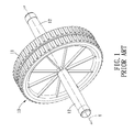
- an exercise equipment which is an abdominal wheel 10 comprises a wheel body 11 and two handles 12 extending in the axial direction Y at both sides of the wheel body 11 .
- the exerciser grips the handles 12 with two hands to roll out the abdominal wheel 10 on the ground and then pulls it back without the body touching the ground. Rolling the abdominal wheel 10 requires strong abdominal muscles.
- the abdominal wheel 10 only has the single wheel body 11 with limited width, therefore, it is difficult for an exerciser with weak abdominal muscles to keep balance when doing workout with the abdominal wheel 10 , and the exerciser may get hurt when loosing balance.
- the present invention has arisen to mitigate and/or obviate the afore-described disadvantages.
- the primary object of the present invention is to provide an abdominal exercise equipment which is provided with two front wheels and two rear wheels, which ensures that the abdominal exercise equipment moves stably without tipping over during movement, preventing the exerciser from losing balance and getting hurt.
- Another object of the present invention is to provide an abdominal exercise equipment which employs a return gear assembly disposed between the two rear wheels to produce a recovering force. Therefore, when the abdominal exercise equipment is pulled back, the recovering force will assist the exerciser to pull the abdominal exercise equipment back, which consequently lowers the difficult level of exercise.
- Yet another object of the present invention is to provide an abdominal exercise equipment which is provided with a vibration device which is capable of softening the muscles and fat, and speeding up fat loss by producing vibration.
- an abdominal exercise equipment in accordance with the present invention comprises: a housing, a rear wheel assembly, a front wheel assembly, a vibration device, a return gear assembly, and two handles.
- the housing includes a longitudinal direction and is formed with a receiving chamber.
- a base of the housing is formed at both sides thereof in the longitudinal direction with two opposite rear-wheel holes, two opposite front-wheel holes, and an assembling hole between the two front-wheel holes.
- the housing is formed at both sides thereof in the longitudinal direction with two inserting holes.
- the rear wheel assembly includes two rear wheels and a gear shaft and is disposed in the receiving chamber in such a manner that the two rear wheels are inserted through the two rear-wheel holes and exposed out of the housing.
- the front wheel assembly includes two front wheels and a connecting shaft.
- the connecting shaft includes a transverse shaft connected between the two front wheels, and in the middle of the transverse shaft is formed a longitudinal shaft to be inserted through the assembling hole of the housing.
- the vibration device is disposed in the receiving chamber of the housing and includes an eccentric wheel and a power source.
- the power source is electrically connected to an electric power supply unit and serves to rotate the eccentric wheel, so as to produce vibration.
- the return gear assembly is disposed in the receiving chamber and comprises a gear and two return members.
- the gear includes a central shaft inserted in the two return members, each of the return members includes an elastic portion in a middle thereof, a transverse leg at one end of the elastic portion to engage with the gear, and a longitudinal leg at another end of the elastic portion to engage with the housing.
- the return gear assembly further includes a two-step gear with a first step portion to be engaged with the gear shaft and a second step portion to be engaged with the gear, and the first step portion has a diameter greater than the second step portion.
- the two handles each include an, assembling member which has one end inserted in the inserting holes of the housing and another end pivotally connected to a gripping rod.
- the gripping rod of one of the handles is provided with a vibration-control switch to control the power source.
- FIG. 1 is a perspective view of a conventional abdominal exercise equipment
- FIG. 2 is a perspective view of an abdominal exercise equipment in accordance with the present invention.
- FIG. 3 is an exploded view of the abdominal exercise equipment in accordance with the present invention.
- FIG. 4A is an exploded view of a vibration device and the handles of the abdominal exercise equipment in accordance with the present invention.
- FIG. 4B is an exploded view of a return gear assembly and the rear wheel assembly of the abdominal exercise equipment in accordance with the present invention
- FIG. 4C is an exploded view of a front wheel assembly and the rear wheel assembly of the abdominal exercise equipment in accordance with the present invention.
- FIG. 5A is an assembly view of the vibration device and the handles of the abdominal exercise equipment in accordance with the present invention.
- FIG. 5B is an assembly view of the return gear assembly and the rear wheel assembly of the abdominal exercise equipment in accordance with the present invention.
- FIG. 5C is an assembly view of the front and rear wheel assemblies of the abdominal exercise equipment in accordance with the present invention.
- FIG. 6A is a top view of the vibration of the abdominal exercise equipment in accordance with the present invention.
- FIG. 6B is a cross sectional view of the vibration device of the abdominal exercise equipment in accordance with the present invention.
- FIG. 7 is a cross sectional view of a part of the abdominal exercise equipment in accordance with the present invention.
- an abdominal exercise equipment in accordance with a preferred embodiment of the present invention comprises a rear wheel assembly 30 , a front wheel assembly 40 , a vibration device 50 and a return gear assembly 60 , which are disposed in a housing 20 , and two handles 70 at both sides of the housing 20 .
- the housing 20 includes a longitudinal direction X and is provided with a base 21 and a cover 22 which are assembled together to form to a receiving chamber 23 .
- the base 21 is formed at both sides thereof in the longitudinal direction X with two opposite rear-wheel holes 211 , two opposite front-wheel holes 212 , and an assembling hole 213 between the two front-wheel holes 212 .
- the cover 22 is formed at both sides thereof in the longitudinal direction X with two inserting holes 221 .
- a mounting frame 24 for mounting and fixing other components.
- On the top of the front wheel assembly 40 is disposed a weight block 25 to improve the stability of the abdominal exercise equipment.
- the mounting frame 24 is formed at the center thereof in the longitudinal direction X with a receiving cavity 241 and further formed with two opposite penetrating holes 242 to be aligned with the inserting holes 221 of the housing 20 .
- the mounting frame 24 is provided at both sides thereof in the longitudinal direction X with two opposite pivot boards 243 which are located adjacent to the rear wheel assembly 30 .
- Each of the pivot boards 243 is formed with a pivot hole 244 and a longitudinal inserting groove 246 . Between the two pivot boards 243 is formed a notch 245 .
- the housing 20 is further provided with a control circuit 26 which includes a control panel 261 disposed on the outer surface of the cover 22 , and the control circuit 26 is electrically connected to an electric power supply unit 262 .
- the rear wheel assembly 30 includes two rear wheels 31 and a gear shaft 32 and disposed in the receiving chamber 23 in such a manner that the two rear wheels 31 are inserted through the two rear-wheel holes 211 and exposed out of the housing 20 .
- the gear shaft 32 includes a connecting shaft 321 and a drive gear 322 mounted on the connecting shaft 321 , and the connecting shaft 321 is connected between the two rear wheels 31 .
- the gear shaft 32 is received in the notch 245 of the mounting frame 24 with the drive gear 322 exposed out of the notch 245 .
- the front wheel assembly 40 includes two front wheels 41 and a reverse T-shaped connecting shaft 42 which includes a transverse shaft 421 connected between the two front wheels 41 .
- a longitudinal shaft 422 In the middle of the transverse shaft 421 is formed a longitudinal shaft 422 to be inserted through the assembling hole 213 of the housing 20 and fixed to the mounting frame 24 .
- the vibration device 50 is disposed in the receiving chamber 23 of the housing 20 and includes an eccentric wheel 51 and a power source 52 .
- the power source 52 is a motor with a drive shaft and electrically connected to the control circuit 26 .
- the power source 52 is connected to the electric power supply unit 262 by the control circuit 26 and serves to rotate the eccentric wheel 51 by using a belt 521 , so as to produce vibration.
- the vibration device 50 includes a shell 53 in which the eccentric wheel 51 and the power source 52 can be fixed.
- the shell 53 is disposed in the receiving cavity 241 of the mounting frame 24 .
- the return gear assembly 60 is disposed in the receiving chamber 23 and comprises a gear 61 and two return members 62 .
- the gear 61 includes a central shaft 611 inserted in the two return members 62 .
- Each of the return members 62 is a helical spring which has an elastic portion 621 in the middle, a transverse leg 622 at one end of the elastic portion 621 to engage with the gear 61 , and a longitudinal leg 623 at another end of the elastic portion 621 to engage with the housing 20 .
- the return gear assembly 60 further includes a two-step gear 63 with a first step portion 631 to be engaged with the gear shaft 32 and a second step portion 632 to be engaged with the gear 61 , and the first step portion 631 has a diameter greater than the second step portion 632 .
- the central shaft 611 of the gear 61 has two ends inserted in the pivot holes 244 of the mounting frame 24 .
- the gear 61 is formed with a transverse inserting hole 612 beside the central shaft 611 , so that the return members 62 have the transverse legs 622 inserted in the transverse inserting hole 612 and have the longitudinal legs 623 inserted in longitudinal inserting holes 246 of the mounting frame 24 .
- the two-step gear 63 includes a central shaft 633 to be pivotally connected to the two pivot boards 243 .
- the two handles 70 each include an assembling member 71 which has one end inserted in the inserting holes 221 of the housing 20 and another end pivotally connected to a gripping rod 72 .
- the gripping rod 72 of one of the handles 70 is provided with a vibration-control switch 73 to be electrically connected to the control circuit 26 to control the power source 52 .
- a hollow pipe 74 to be inserted in the two penetrating holes 242 of the mounting frame 24 , and the assembling members 71 are inserted through the inserting holes 221 of the cover 22 and into the hollow pipe 74 .
- Each of the gripping rods 72 includes two semicircular hollow rods 721 clamped together to form a cylindrical structure, and a sleeve 722 is sleeved on the cylindrical structure.
- the assembling member 71 of each of the two handles 70 is formed at an end thereof with a pivot notch 711 , and the gripping rods 72 are pivotally fixed in the pivot notch 711 by a pivot 75 .
- the abdominal exercise equipment of the present invention is put on the ground, the exerciser holds the two handles 70 with two hands and keeps feet on the ground, and then does workout by pushing out the abdominal exercise equipment and pulling it back repeatedly, so as to exercise the abdominal muscles. Since the front and rear wheel assemblies 40 , 30 of the abdominal exercise equipment of the present invention touch the ground with four wheels, which ensures that the abdominal exercise equipment moves stably without tipping over during movement, preventing the exerciser from losing balance and getting hurt.
- the return gear assembly 60 is disposed between the two rear wheels 31 in such a manner that the transverse legs 622 of the two return members 62 are fixed to the gear 61 of the return gear assembly 60 , and the longitudinal legs 623 are fixed to the mounting frame 24 .
- the rear wheels 31 will use the two-step gear 63 to rotate the gear 61 , and the transverse legs 622 of the two return members 62 will also be rotated to make the elastic portion 621 of the return members 62 deform and consequently produce a recovering force. Therefore, when the abdominal exercise equipment is pulled back, the recovering force will assist the exerciser to pull the abdominal exercise equipment back, which consequently lowers the difficult level of exercise.
- the vibration device 50 is disposed between the two handles 70 , the vibration produced by the vibration device 50 can be transferred to the exerciser's upper limbs through the two handles 70 to soften the muscles and fat, and speed up fat loss.
Landscapes
- Health & Medical Sciences (AREA)
- Physical Education & Sports Medicine (AREA)
- General Health & Medical Sciences (AREA)
- Orthopedic Medicine & Surgery (AREA)
- Biophysics (AREA)
- Life Sciences & Earth Sciences (AREA)
- Vascular Medicine (AREA)
- Cardiology (AREA)
- Engineering & Computer Science (AREA)
- Biomedical Technology (AREA)
- Neurology (AREA)
- Pulmonology (AREA)
- Rehabilitation Tools (AREA)
Abstract
Description
Claims (10)
Priority Applications (1)
| Application Number | Priority Date | Filing Date | Title |
|---|---|---|---|
| US13/452,856 US8708874B2 (en) | 2012-04-21 | 2012-04-21 | Abdominal exercise equipment |
Applications Claiming Priority (1)
| Application Number | Priority Date | Filing Date | Title |
|---|---|---|---|
| US13/452,856 US8708874B2 (en) | 2012-04-21 | 2012-04-21 | Abdominal exercise equipment |
Publications (2)
| Publication Number | Publication Date |
|---|---|
| US20130281270A1 US20130281270A1 (en) | 2013-10-24 |
| US8708874B2 true US8708874B2 (en) | 2014-04-29 |
Family
ID=49380632
Family Applications (1)
| Application Number | Title | Priority Date | Filing Date |
|---|---|---|---|
| US13/452,856 Expired - Fee Related US8708874B2 (en) | 2012-04-21 | 2012-04-21 | Abdominal exercise equipment |
Country Status (1)
| Country | Link |
|---|---|
| US (1) | US8708874B2 (en) |
Cited By (7)
| Publication number | Priority date | Publication date | Assignee | Title |
|---|---|---|---|---|
| CN106139527A (en) * | 2016-08-05 | 2016-11-23 | 许高禹 | A kind of combination type abdominal muscles exercise device |
| US9814927B2 (en) | 2016-02-26 | 2017-11-14 | Leon Forystek | Abdominal exercise apparatus |
| US9868024B2 (en) | 2015-02-05 | 2018-01-16 | Salvatore Castelluccio | Abdominal and oblique exercise device |
| US10549150B2 (en) * | 2016-06-17 | 2020-02-04 | Taizhou Huangyan Ankang Fitness Equipment Co., Ltd. | Multifunctional abdominal exercise wheel |
| EP3613475A1 (en) * | 2018-08-24 | 2020-02-26 | Lung-Fei Chuang | Sporting device |
| EP3613473A1 (en) * | 2018-08-24 | 2020-02-26 | Lung-Fei Chuang | Restoring mechanism and exercising device |
| US20230094565A1 (en) * | 2021-09-28 | 2023-03-30 | T. K. Chin Company Ltd. | Adjustable ab wheel |
Families Citing this family (14)
| Publication number | Priority date | Publication date | Assignee | Title |
|---|---|---|---|---|
| USD745614S1 (en) * | 2014-11-24 | 2015-12-15 | Wei-Teh Ho | Wheel roller exerciser |
| USD816783S1 (en) * | 2015-04-13 | 2018-05-01 | Xystus, Llc | Abdominal exercise wheel |
| USD815217S1 (en) * | 2015-04-13 | 2018-04-10 | Xystus, Llc | Abdominal exercise wheel |
| USD827738S1 (en) * | 2015-04-13 | 2018-09-04 | Xystus, Llc | Abdominal exercise wheel |
| USD818544S1 (en) * | 2015-04-13 | 2018-05-22 | Xystus, Llc | Abdominal Exercise Wheel |
| US20180272185A1 (en) * | 2017-03-22 | 2018-09-27 | Michael Stuart Barber | Exercise device |
| US10843033B1 (en) * | 2018-03-08 | 2020-11-24 | Prism Fitness, Inc. | Core wheel with collapsible handles |
| USD877822S1 (en) * | 2018-10-02 | 2020-03-10 | Exemplar Design, Llc | AB roller |
| USD861808S1 (en) * | 2019-04-22 | 2019-10-01 | Beijing Jifeng Technology Co., Limited | Abdominal wheel |
| CN110898392A (en) * | 2019-12-06 | 2020-03-24 | 江苏盐西世纪教育产业项目开发有限公司 | Portable athlete physical ability auxiliary training device |
| CN113304439A (en) * | 2021-07-06 | 2021-08-27 | 上海兽鸟智能科技有限公司 | Multifunctional exercise wheel |
| USD998068S1 (en) * | 2021-12-07 | 2023-09-05 | Bala Bangles, Inc. | Abdominal exercise wheel |
| USD986992S1 (en) * | 2022-07-28 | 2023-05-23 | Tan Jiang | Roller wheel |
| USD991372S1 (en) * | 2022-09-30 | 2023-07-04 | Jinyun Fu | Roller wheel |
Citations (25)
| Publication number | Priority date | Publication date | Assignee | Title |
|---|---|---|---|---|
| US3861382A (en) * | 1973-10-11 | 1975-01-21 | Luther G Simjian | Exercise and massaging apparatus |
| US4136867A (en) * | 1977-05-31 | 1979-01-30 | Wilkin Douglas G | Vibrating exercising wheel |
| US5123406A (en) * | 1988-11-17 | 1992-06-23 | Nihonkenkozoshinkenkyukai Co., Ltd. | Motor-driven massaging apparatus |
| US6017296A (en) * | 1999-07-09 | 2000-01-25 | Tang; Jack | Exercise wheel |
| US6071217A (en) * | 1996-10-24 | 2000-06-06 | Barnett; Larry W. | Prone torso exerciser |
| US6146318A (en) * | 1999-07-01 | 2000-11-14 | Chin Tsun Lee | Push and pull type roller exerciser |
| US6174269B1 (en) * | 1999-11-15 | 2001-01-16 | Paul William Eschenbach | Push-pull tractor exercise apparatus |
| US6254518B1 (en) * | 2000-02-29 | 2001-07-03 | Chen Chang Co., Ltd. | Exercise wheel |
| US6264587B1 (en) * | 2000-04-12 | 2001-07-24 | Chin-Tsun Lee | Exercise wheel |
| US6338703B1 (en) * | 1999-04-14 | 2002-01-15 | Sam Tsai | Sliding exerciser |
| US6348027B1 (en) * | 2000-08-14 | 2002-02-19 | Chin-Tsun Lee | Exercise wheel |
| US20020025894A1 (en) * | 2000-08-29 | 2002-02-28 | Juan Fernandez | Wheeled exerciser |
| US6354983B1 (en) * | 2001-02-12 | 2002-03-12 | Chin-Tsun Lee | Exercise wheel |
| US6368259B1 (en) * | 2000-12-18 | 2002-04-09 | Lung-An Liao | Damping assembly for an exerciser |
| US6409639B1 (en) * | 2001-08-10 | 2002-06-25 | Hsiu-Min Kuo | Structure of exercise wheel |
| US20020123416A1 (en) * | 2001-03-02 | 2002-09-05 | Huang Chin Chiu | Body building roller |
| US6544153B2 (en) * | 2001-07-19 | 2003-04-08 | Chin-Tsun Lee | Exercise wheel |
| US20030073937A1 (en) * | 2000-06-09 | 2003-04-17 | Louis-Paul Guitay | Massage apparatus comprising at least one roller driven positively in rotation |
| US6634995B1 (en) * | 2001-06-28 | 2003-10-21 | Stretch Power Llc | Manually operated stretching apparatus |
| US6638201B1 (en) * | 2001-10-25 | 2003-10-28 | Delphi Oracle Corp. | Cam action exercise apparatus with asymmetric energy management |
| US20050009672A1 (en) * | 2003-07-11 | 2005-01-13 | Yong-Song Yeh | Magnetic tension control weight training machine |
| US7041072B2 (en) * | 2002-02-21 | 2006-05-09 | Matrix Surgical Consulting Corporation | Massager and method of using same |
| US20060211961A1 (en) * | 2005-03-18 | 2006-09-21 | Meyer Elizabeth H | Massager with shock absorption, multiple contact surfaces and visual therapy effects |
| US20090176635A1 (en) * | 2008-01-09 | 2009-07-09 | Todd Brinson | Exercise Device |
| US20110143895A1 (en) * | 2009-12-14 | 2011-06-16 | Jack Tang | Exercise wheel |
-
2012
- 2012-04-21 US US13/452,856 patent/US8708874B2/en not_active Expired - Fee Related
Patent Citations (26)
| Publication number | Priority date | Publication date | Assignee | Title |
|---|---|---|---|---|
| US3861382A (en) * | 1973-10-11 | 1975-01-21 | Luther G Simjian | Exercise and massaging apparatus |
| US4136867A (en) * | 1977-05-31 | 1979-01-30 | Wilkin Douglas G | Vibrating exercising wheel |
| US5123406A (en) * | 1988-11-17 | 1992-06-23 | Nihonkenkozoshinkenkyukai Co., Ltd. | Motor-driven massaging apparatus |
| US6071217A (en) * | 1996-10-24 | 2000-06-06 | Barnett; Larry W. | Prone torso exerciser |
| US6338703B1 (en) * | 1999-04-14 | 2002-01-15 | Sam Tsai | Sliding exerciser |
| US6146318A (en) * | 1999-07-01 | 2000-11-14 | Chin Tsun Lee | Push and pull type roller exerciser |
| US6017296A (en) * | 1999-07-09 | 2000-01-25 | Tang; Jack | Exercise wheel |
| US6174269B1 (en) * | 1999-11-15 | 2001-01-16 | Paul William Eschenbach | Push-pull tractor exercise apparatus |
| US6254518B1 (en) * | 2000-02-29 | 2001-07-03 | Chen Chang Co., Ltd. | Exercise wheel |
| US6264587B1 (en) * | 2000-04-12 | 2001-07-24 | Chin-Tsun Lee | Exercise wheel |
| US20030073937A1 (en) * | 2000-06-09 | 2003-04-17 | Louis-Paul Guitay | Massage apparatus comprising at least one roller driven positively in rotation |
| US6348027B1 (en) * | 2000-08-14 | 2002-02-19 | Chin-Tsun Lee | Exercise wheel |
| US20020025894A1 (en) * | 2000-08-29 | 2002-02-28 | Juan Fernandez | Wheeled exerciser |
| US6368259B1 (en) * | 2000-12-18 | 2002-04-09 | Lung-An Liao | Damping assembly for an exerciser |
| US6354983B1 (en) * | 2001-02-12 | 2002-03-12 | Chin-Tsun Lee | Exercise wheel |
| US20020123416A1 (en) * | 2001-03-02 | 2002-09-05 | Huang Chin Chiu | Body building roller |
| US6634995B1 (en) * | 2001-06-28 | 2003-10-21 | Stretch Power Llc | Manually operated stretching apparatus |
| US6544153B2 (en) * | 2001-07-19 | 2003-04-08 | Chin-Tsun Lee | Exercise wheel |
| US6409639B1 (en) * | 2001-08-10 | 2002-06-25 | Hsiu-Min Kuo | Structure of exercise wheel |
| US6638201B1 (en) * | 2001-10-25 | 2003-10-28 | Delphi Oracle Corp. | Cam action exercise apparatus with asymmetric energy management |
| US7041072B2 (en) * | 2002-02-21 | 2006-05-09 | Matrix Surgical Consulting Corporation | Massager and method of using same |
| US20050009672A1 (en) * | 2003-07-11 | 2005-01-13 | Yong-Song Yeh | Magnetic tension control weight training machine |
| US6857993B2 (en) * | 2003-07-11 | 2005-02-22 | Yong-Song Yeh | Magnetic tension control weight training machine |
| US20060211961A1 (en) * | 2005-03-18 | 2006-09-21 | Meyer Elizabeth H | Massager with shock absorption, multiple contact surfaces and visual therapy effects |
| US20090176635A1 (en) * | 2008-01-09 | 2009-07-09 | Todd Brinson | Exercise Device |
| US20110143895A1 (en) * | 2009-12-14 | 2011-06-16 | Jack Tang | Exercise wheel |
Cited By (8)
| Publication number | Priority date | Publication date | Assignee | Title |
|---|---|---|---|---|
| US9868024B2 (en) | 2015-02-05 | 2018-01-16 | Salvatore Castelluccio | Abdominal and oblique exercise device |
| US9814927B2 (en) | 2016-02-26 | 2017-11-14 | Leon Forystek | Abdominal exercise apparatus |
| US10549150B2 (en) * | 2016-06-17 | 2020-02-04 | Taizhou Huangyan Ankang Fitness Equipment Co., Ltd. | Multifunctional abdominal exercise wheel |
| CN106139527A (en) * | 2016-08-05 | 2016-11-23 | 许高禹 | A kind of combination type abdominal muscles exercise device |
| EP3613475A1 (en) * | 2018-08-24 | 2020-02-26 | Lung-Fei Chuang | Sporting device |
| EP3613473A1 (en) * | 2018-08-24 | 2020-02-26 | Lung-Fei Chuang | Restoring mechanism and exercising device |
| US20230094565A1 (en) * | 2021-09-28 | 2023-03-30 | T. K. Chin Company Ltd. | Adjustable ab wheel |
| US11918853B2 (en) * | 2021-09-28 | 2024-03-05 | T. K. Chin Company Ltd. | Adjustable AB wheel |
Also Published As
| Publication number | Publication date |
|---|---|
| US20130281270A1 (en) | 2013-10-24 |
Similar Documents
| Publication | Publication Date | Title |
|---|---|---|
| US8708874B2 (en) | Abdominal exercise equipment | |
| US7285079B2 (en) | Exercise device and methods | |
| US7794361B2 (en) | Swing handle arrangement for an exercise equipment | |
| EP2769753A1 (en) | Total body exercise equipment | |
| US20060252607A1 (en) | Vertical total body exercise apparatus | |
| US20130123078A1 (en) | Double rollers exercise device | |
| US7727121B1 (en) | Stepping and waist-twisting exerciser | |
| EP3272400A1 (en) | Novel rowing exercise machine | |
| EP3613475A1 (en) | Sporting device | |
| CN210278129U (en) | Leg muscle exercising apparatus | |
| CN106005213B (en) | A kind of child's scooter constantly to be advanced using human body recoil | |
| JP2009219576A (en) | Vibration exercise equipment | |
| US20140066261A1 (en) | Swing handle arrangement for an exercise equipment | |
| KR101209432B1 (en) | A | |
| CN203139490U (en) | Double-person seesaw lever | |
| CN202605639U (en) | Abdominal exerciser | |
| CN103120847A (en) | Double see-saw lever | |
| CN203389282U (en) | Household fitness equipment | |
| US20130267388A1 (en) | Swing handle arrangement for an exercise equipment | |
| CN205683479U (en) | Multifunctional abdomen strengthening is taken turns | |
| KR200271300Y1 (en) | Sliding athletic apparatus having a connection bar | |
| CN106267737B (en) | A kind of omnipotent training stand of dancing basic training | |
| JP3177006U (en) | Abdominal training device | |
| CN210159162U (en) | Steel sheet spring body-building wheel | |
| CN201949559U (en) | Assembled waist and abdomen fitness device |
Legal Events
| Date | Code | Title | Description |
|---|---|---|---|
| AS | Assignment |
Owner name: LISTORE INTERNATIONAL CO., LTD., TAIWAN Free format text: ASSIGNMENT OF ASSIGNORS INTEREST;ASSIGNOR:CHEN, JUI-YAO;REEL/FRAME:028085/0668 Effective date: 20120412 |
|
| FEPP | Fee payment procedure |
Free format text: PAYOR NUMBER ASSIGNED (ORIGINAL EVENT CODE: ASPN); ENTITY STATUS OF PATENT OWNER: SMALL ENTITY |
|
| AS | Assignment |
Owner name: TRISTAR PRODUCTS INC., NEW JERSEY Free format text: ASSIGNMENT OF ASSIGNORS INTEREST;ASSIGNOR:LISTORE INTERNATIONAL CO., LTD.;REEL/FRAME:031953/0900 Effective date: 20131218 |
|
| FEPP | Fee payment procedure |
Free format text: MAINTENANCE FEE REMINDER MAILED (ORIGINAL EVENT CODE: REM.) |
|
| LAPS | Lapse for failure to pay maintenance fees |
Free format text: PATENT EXPIRED FOR FAILURE TO PAY MAINTENANCE FEES (ORIGINAL EVENT CODE: EXP.) |
|
| FP | Lapsed due to failure to pay maintenance fee |
Effective date: 20180429 |
|
| PRDP | Patent reinstated due to the acceptance of a late maintenance fee |
Effective date: 20180912 |
|
| FEPP | Fee payment procedure |
Free format text: SURCHARGE, PETITION TO ACCEPT PYMT AFTER EXP, UNINTENTIONAL. (ORIGINAL EVENT CODE: M2558); ENTITY STATUS OF PATENT OWNER: SMALL ENTITY Free format text: PETITION RELATED TO MAINTENANCE FEES FILED (ORIGINAL EVENT CODE: PMFP); ENTITY STATUS OF PATENT OWNER: SMALL ENTITY Free format text: PETITION RELATED TO MAINTENANCE FEES GRANTED (ORIGINAL EVENT CODE: PMFG); ENTITY STATUS OF PATENT OWNER: SMALL ENTITY |
|
| MAFP | Maintenance fee payment |
Free format text: PAYMENT OF MAINTENANCE FEE, 4TH YR, SMALL ENTITY (ORIGINAL EVENT CODE: M2551); ENTITY STATUS OF PATENT OWNER: SMALL ENTITY Year of fee payment: 4 |
|
| STCF | Information on status: patent grant |
Free format text: PATENTED CASE |
|
| FEPP | Fee payment procedure |
Free format text: MAINTENANCE FEE REMINDER MAILED (ORIGINAL EVENT CODE: REM.); ENTITY STATUS OF PATENT OWNER: SMALL ENTITY |
|
| LAPS | Lapse for failure to pay maintenance fees |
Free format text: PATENT EXPIRED FOR FAILURE TO PAY MAINTENANCE FEES (ORIGINAL EVENT CODE: EXP.); ENTITY STATUS OF PATENT OWNER: SMALL ENTITY |
|
| STCH | Information on status: patent discontinuation |
Free format text: PATENT EXPIRED DUE TO NONPAYMENT OF MAINTENANCE FEES UNDER 37 CFR 1.362 |
|
| FP | Lapsed due to failure to pay maintenance fee |
Effective date: 20220429 |