US8680774B2 - Electronic system and an electronic module therefor - Google Patents
Electronic system and an electronic module therefor Download PDFInfo
- Publication number
- US8680774B2 US8680774B2 US13/508,555 US201013508555A US8680774B2 US 8680774 B2 US8680774 B2 US 8680774B2 US 201013508555 A US201013508555 A US 201013508555A US 8680774 B2 US8680774 B2 US 8680774B2
- Authority
- US
- United States
- Prior art keywords
- electronic module
- tracks
- electronic
- electronic system
- power
- Prior art date
- Legal status (The legal status is an assumption and is not a legal conclusion. Google has not performed a legal analysis and makes no representation as to the accuracy of the status listed.)
- Active, expires
Links
Images


Classifications
-
- F—MECHANICAL ENGINEERING; LIGHTING; HEATING; WEAPONS; BLASTING
- F21—LIGHTING
- F21V—FUNCTIONAL FEATURES OR DETAILS OF LIGHTING DEVICES OR SYSTEMS THEREOF; STRUCTURAL COMBINATIONS OF LIGHTING DEVICES WITH OTHER ARTICLES, NOT OTHERWISE PROVIDED FOR
- F21V21/00—Supporting, suspending, or attaching arrangements for lighting devices; Hand grips
- F21V21/34—Supporting elements displaceable along a guiding element
- F21V21/35—Supporting elements displaceable along a guiding element with direct electrical contact between the supporting element and electric conductors running along the guiding element
-
- F—MECHANICAL ENGINEERING; LIGHTING; HEATING; WEAPONS; BLASTING
- F21—LIGHTING
- F21V—FUNCTIONAL FEATURES OR DETAILS OF LIGHTING DEVICES OR SYSTEMS THEREOF; STRUCTURAL COMBINATIONS OF LIGHTING DEVICES WITH OTHER ARTICLES, NOT OTHERWISE PROVIDED FOR
- F21V33/00—Structural combinations of lighting devices with other articles, not otherwise provided for
- F21V33/0004—Personal or domestic articles
- F21V33/0012—Furniture
-
- H—ELECTRICITY
- H01—ELECTRIC ELEMENTS
- H01R—ELECTRICALLY-CONDUCTIVE CONNECTIONS; STRUCTURAL ASSOCIATIONS OF A PLURALITY OF MUTUALLY-INSULATED ELECTRICAL CONNECTING ELEMENTS; COUPLING DEVICES; CURRENT COLLECTORS
- H01R25/00—Coupling parts adapted for simultaneous co-operation with two or more identical counterparts, e.g. for distributing energy to two or more circuits
- H01R25/14—Rails or bus-bars constructed so that the counterparts can be connected thereto at any point along their length
- H01R25/142—Their counterparts
-
- H—ELECTRICITY
- H05—ELECTRIC TECHNIQUES NOT OTHERWISE PROVIDED FOR
- H05B—ELECTRIC HEATING; ELECTRIC LIGHT SOURCES NOT OTHERWISE PROVIDED FOR; CIRCUIT ARRANGEMENTS FOR ELECTRIC LIGHT SOURCES, IN GENERAL
- H05B45/00—Circuit arrangements for operating light-emitting diodes [LED]
- H05B45/20—Controlling the colour of the light
-
- H—ELECTRICITY
- H05—ELECTRIC TECHNIQUES NOT OTHERWISE PROVIDED FOR
- H05B—ELECTRIC HEATING; ELECTRIC LIGHT SOURCES NOT OTHERWISE PROVIDED FOR; CIRCUIT ARRANGEMENTS FOR ELECTRIC LIGHT SOURCES, IN GENERAL
- H05B47/00—Circuit arrangements for operating light sources in general, i.e. where the type of light source is not relevant
- H05B47/10—Controlling the light source
- H05B47/105—Controlling the light source in response to determined parameters
-
- F—MECHANICAL ENGINEERING; LIGHTING; HEATING; WEAPONS; BLASTING
- F21—LIGHTING
- F21S—NON-PORTABLE LIGHTING DEVICES; SYSTEMS THEREOF; VEHICLE LIGHTING DEVICES SPECIALLY ADAPTED FOR VEHICLE EXTERIORS
- F21S10/00—Lighting devices or systems producing a varying lighting effect
- F21S10/02—Lighting devices or systems producing a varying lighting effect changing colors
- F21S10/026—Lighting devices or systems producing a varying lighting effect changing colors by movement of parts, e.g. by movement of reflectors or light sources
-
- F—MECHANICAL ENGINEERING; LIGHTING; HEATING; WEAPONS; BLASTING
- F21—LIGHTING
- F21S—NON-PORTABLE LIGHTING DEVICES; SYSTEMS THEREOF; VEHICLE LIGHTING DEVICES SPECIALLY ADAPTED FOR VEHICLE EXTERIORS
- F21S9/00—Lighting devices with a built-in power supply; Systems employing lighting devices with a built-in power supply
- F21S9/02—Lighting devices with a built-in power supply; Systems employing lighting devices with a built-in power supply the power supply being a battery or accumulator
-
- F—MECHANICAL ENGINEERING; LIGHTING; HEATING; WEAPONS; BLASTING
- F21—LIGHTING
- F21V—FUNCTIONAL FEATURES OR DETAILS OF LIGHTING DEVICES OR SYSTEMS THEREOF; STRUCTURAL COMBINATIONS OF LIGHTING DEVICES WITH OTHER ARTICLES, NOT OTHERWISE PROVIDED FOR
- F21V21/00—Supporting, suspending, or attaching arrangements for lighting devices; Hand grips
- F21V21/08—Devices for easy attachment to any desired place, e.g. clip, clamp, magnet
- F21V21/096—Magnetic devices
-
- H—ELECTRICITY
- H01—ELECTRIC ELEMENTS
- H01R—ELECTRICALLY-CONDUCTIVE CONNECTIONS; STRUCTURAL ASSOCIATIONS OF A PLURALITY OF MUTUALLY-INSULATED ELECTRICAL CONNECTING ELEMENTS; COUPLING DEVICES; CURRENT COLLECTORS
- H01R13/00—Details of coupling devices of the kinds covered by groups H01R12/70 or H01R24/00 - H01R33/00
- H01R13/02—Contact members
- H01R13/03—Contact members characterised by the material, e.g. plating, or coating materials
-
- H—ELECTRICITY
- H01—ELECTRIC ELEMENTS
- H01R—ELECTRICALLY-CONDUCTIVE CONNECTIONS; STRUCTURAL ASSOCIATIONS OF A PLURALITY OF MUTUALLY-INSULATED ELECTRICAL CONNECTING ELEMENTS; COUPLING DEVICES; CURRENT COLLECTORS
- H01R2103/00—Two poles
-
- H—ELECTRICITY
- H01—ELECTRIC ELEMENTS
- H01R—ELECTRICALLY-CONDUCTIVE CONNECTIONS; STRUCTURAL ASSOCIATIONS OF A PLURALITY OF MUTUALLY-INSULATED ELECTRICAL CONNECTING ELEMENTS; COUPLING DEVICES; CURRENT COLLECTORS
- H01R25/00—Coupling parts adapted for simultaneous co-operation with two or more identical counterparts, e.g. for distributing energy to two or more circuits
- H01R25/14—Rails or bus-bars constructed so that the counterparts can be connected thereto at any point along their length
- H01R25/147—Low voltage devices, i.e. safe to touch live conductors
-
- H—ELECTRICITY
- H02—GENERATION; CONVERSION OR DISTRIBUTION OF ELECTRIC POWER
- H02J—CIRCUIT ARRANGEMENTS OR SYSTEMS FOR SUPPLYING OR DISTRIBUTING ELECTRIC POWER; SYSTEMS FOR STORING ELECTRIC ENERGY
- H02J50/00—Circuit arrangements or systems for wireless supply or distribution of electric power
- H02J50/10—Circuit arrangements or systems for wireless supply or distribution of electric power using inductive coupling
Definitions
- the invention relates to an electronic system comprising at least a base part, a power source and at least one electronic module adapted to be powered by the power source.
- the base part is provided with a number of primary coils, whilst the electronic module is provided with a secondary coil.
- the electronic module can be positioned on the base part, in which case power is transmitted from the primary coils to the secondary coil to power a light element of the electronic module.
- a disadvantage of this known system is that it is relatively difficult for a user to amend the power to the light element in order to be able to dim the light.
- the base part is provided with at least two parallel extending, elongated tracks being electrically conductive, wherein at least one parameter of the electronic module is changeable by amending the distance of the electronic module to a predetermined location on the tracks.
- the parameter may, for example, be the power output of the electronic module.
- the electronic module comprises a light element he will notice that the further the electronic module is away from a predetermined location on the track, the less light will be transmitted by the light element, since less power is transmitted to the electronic module.
- An embodiment of the electronic system according to the invention is characterized in that the electronic module is provided with at least two contacting elements, each adapted to interact with one of the tracks at a plurality of positions along the tracks, wherein the parameter is the power to the electronic module, which power decreases with an increase of the distance to the predetermined location on the tracks.
- the power can be transmitted from a power source to the electronic module via the tracks or can be transmitted to an electronic element of the electronic module by a battery of the electronic module.
- Another embodiment of the electronic system according to the invention is characterized in that at the predetermined location the tracks are connected to the power source, and each track has a relatively high electric resistance of at least 1 Ohm/square, due to which the power to the electronic module decreases with an increase of the distance of the electronic module to the power source.
- the power to the electronic module will automatically decrease when the distance increases to the location where the tracks are connected to the power source. For a user it will be intuitively clear that the further away the electronic module is from the power source, the less power will be available at the electronic module.
- Another embodiment of the electronic system according to the invention is characterized in that the electronic system is provided with control means to calculate the electric resistance between the electronic module and the predetermined location via the tracks to determine the position of the electronic module on the tracks and to amend at least one parameter of the electronic module, depending on the distance between the calculated position and the predetermined location on the tracks.
- the electric resistance can easily be calculated. Based on the calculated electric resistance, the distance between the calculated position and the predetermined location on the tracks can be determined and the parameter can be changed.
- This embodiment is particularly suitable for tracks with a relatively low electric resistance, and the predetermined location need not be determined by the location where the tracks are connected to the power source but can be chosen by the person installing the electronic system. The predetermined location will be chosen so that it will be logical and intuitive for a user.
- the electronic module comprises a light element
- a dimmer on the electronic module or at the power source can be activated, based on the distance between the calculated position and the predetermined location on the tracks.
- the power will be transmitted to the electronic module by other means than the tracks.
- Yet another embodiment of the electronic system according to the invention is characterized in that the parameter of the electronic module, being the power, color, color temperature, hue or saturation etc, can be changed by the control means, depending on the distance between the calculated position and the predetermined location on the tracks.
- the parameter of the electronic module being the power, color, color temperature, hue or saturation etc
- Any parameter of the electronic module can be chosen to be changed by the control means, in which case the parameter will be changed by amending the distance from the electronic module to the predetermined location. Also these amendments can be chosen so as to feel logical to the user. So, for example, the brighter the light source, the higher the color temperature; the further away from the predetermined location, the less saturation, etc. The color itself can be changed following the colors of a rainbow changing from red to orange to yellow to green to blue to purple, the further the electronic module is away from the predetermined location.
- a further embodiment of the electronic system according to the invention is characterized in that the power source comprises a number of primary coils located along at least one of the tracks, while the electronic module comprises a secondary coil interacting with at least one of the primary coils.
- Yet another embodiment of the electronic system according to the invention is characterized in that the power to the electronic module linearly decreases with an increase of the distance to the predetermined location on the tracks.
- each track comprises an indium tin oxide (ITO) film.
- ITO indium tin oxide
- Such a film is transparent and will be almost invisible to a user, so that it will not mar the wall or device on which the base part is attached. This provides more freedom in the design of the electronic system. Furthermore, if the tracks are clearly visible a user might have the feeling that touching the tracks is unsafe or dangerous. However, in the case that a low voltage is applied to the tracks there is no risk that a user will get an electric shock. By using almost invisible tracks this feeling of a user will be reduced. ITO has a relatively high electric resistance which renders it very suitable for determining the position of the electronic module with respect to the predetermined location.
- Yet another embodiment of the electronic system according to the invention is characterized in that the base part and the electronic module are releasably magnetically attached to each other.
- the electronic module can easily be repositioned with respect to the base part.
- Yet another embodiment of the electronic system according to the invention is characterized in that the electronic module comprises a light element.
- the light element can easily be dimmed by placing the electronic module at another location on the tracks.
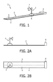
- FIG. 1 is a perspective view of an electronic system according to the invention
- FIGS. 2A and 2B are a side view and top view, respectively, of the electronic system as shown in FIG. 1 ,
- FIG. 3 is a cross section of the electronic system as shown in FIG. 1 ,
- FIG. 4 is a schematic view of the working principle of the electronic system as shown in FIGS. 1-3 ,
- FIG. 5 is a cross section of another embodiment of the electronic system according to the invention.
- FIG. 6 is a top view of the electronic system as shown in FIG. 1 or 5 , showing the dimming of the light emitted by the electronic module,
- FIG. 7 is a perspective view of another electronic system according to the invention, comprising multiple tracks
- FIG. 8 is a perspective view of an application of the electronic system according to the invention.
- FIGS. 9-11 are top views of three further embodiments of the electronic system according to the invention.
- FIGS. 12A and 12B are top views of the electronic system according to the invention, with different orientations of the electronic module with respect to the tracks.
- FIGS. 1 , 2 A, 2 B and 3 show different views of an electronic system 1 according to the invention.
- the electronic system 1 comprises a base part 2 and an electronic module 3 .
- the base part 2 is provided with a carrier 4 and two longitudinal films 5 of ITO.
- the films 5 extend parallel to each other and are connected near one end to a power source 6 .
- the power source 6 might comprise batteries or might be a low voltage source connected to the mains.
- the electronic module 3 comprises a light element 7 positioned on the tracks 5 by means of a foot 8 .
- FIG. 3 shows a cross section of the electronic system 1 according to the invention.
- the carrier 4 of the base part 2 is provided with a ferromagnetic layer 9 located below the tracks 5 .
- the electronic module 3 is provided with two contacting elements 10 located at a distance from each other, which distance is almost equal to the distance between the central axes of the tracks 5 .
- the contacting elements 10 are connected to the light element 7 by means of wires 11 . Between the contacting elements 10 a permanent magnet 12 is located.
- the electronic module 3 is releasably attached to the base part 2 by means of magnetic forces between the permanent magnet 12 and the ferromagnetic layer 9 . By attaching the electronic module 3 to the base part 2 , the contacting elements 10 are positioned against the tracks 5 and are electrically connected therewith.
- the tracks 5 and the electronic module 3 may comprise mechanical means to orientate the electronic module 3 with respect to the tracks. It is also possible to provide the electronic module 3 with several contacting elements 10 (see FIGS. 12A and 12B ), such that each contacting element 10 is in contact with one track 5 or none of the tracks 5 , but never with both tracks. By using an electronic circuit, short circuits between two contacting elements 10 on the same track 5 can easily be prevented.
- the electric resistance of the tracks 5 is relatively high, for example 1-5 Ohm/square, due to which the placement of the electronic module 3 at a larger distance from the power source 6 will automatically result in less power to the electronic module 3 and therefore less light emitted by the light element 7 .
- FIG. 4 shows schematically the electronic system 1 according to the invention.
- the larger the distance L the larger the resistance Rtrack of the tracks 5 will be.
- an ITO film is used with a thickness of 240 nm, a width W of 4 cm and a resistivity Rsquare of 5 Ohm/square.
- the optical transmittance of the ITO film is 80%.
- the minimum track length L is 5 cm and the maximum track length L is 100 cm.
- FIG. 5 shows a cross section of a second embodiment of an electronic system 21 according to the invention.
- the electronic system 21 comprises a base part 22 and an electronic module 23 .
- the base part 22 is provided with a carrier 24 and two longitudinal films 25 of ITO.
- the films 25 extend parallel to each other and are connected near one end to an additional power source (not shown).
- the base part 22 is further provided with a number of primary coils 26 located below the tracks 25 in a row extending parallel to the tracks 25 and powered by a mains power source.
- the electronic module 23 comprises a light element 27 positioned on the tracks 25 by means of a foot 28 .
- the electronic module 23 is provided with two contacting elements 30 located at a distance from each other, which distance is almost equal to the distance between the central axes of the tracks 25 .
- the contacting elements 30 are connected to a control means 31 .
- the electronic module 23 is also provided with a secondary coil 32 located between the contacting elements 30 .
- the secondary coil 32 and the light element 27 are connected to the control means 31 .
- the electronic module 23 can be releasably located and connected to the base part 22 by means of gravity.
- the contacting elements 30 are positioned against the tracks 25 and are electrically connected therewith.
- the control means 31 By means of the control means 31 , the position of the electronic module 23 with respect to a predetermined location on the tracks 25 can be calculated, for example based on the voltage applied and the current as measured. Power will be transmitted by the primary coils 26 to the secondary coil 29 . Based on the distance to the predetermined location, the desired amount of power is transmitted to the light element 27 by the control means 31 .
- the control means 31 also other parameters of the light element 27 like the color, color temperature, hue, saturation etc. may be amended.
- FIG. 7 shows a perspective view of a third embodiment of an electronic system 41 according to the invention comprising a base part 42 and two electronic modules 43 .
- the base part 42 is provided with a carrier 44 and a plurality of parallel tracks 45 connected near one end to a power source 46 .
- Each electronic module 43 will interact with two adjacent tracks 45 in order to be supplied with power.
- FIG. 8 shows an application of the electronic system 1 according to the invention, in which the tracks 5 are mounted on a desk 51 .
- a user may move the electronic module 3 from the left to the right, thereby automatically causing the amount of emitted light to be amended.
- FIG. 9 shows an embodiment of the electronic system 61 according to the invention, comprising two tracks 65 on which an electronic module 63 with a light element 67 is mounted.
- the electronic module 63 is movable along the tracks 65 in the directions indicated by the double arrow P 1 .
- the electronic system 61 further comprises a power source 66 mounted by means of a power module 68 on the tracks 5 .
- the power module 68 is movable along the tracks 65 in the directions indicated by the double arrow P 2 . Between the power module 68 and the electronic module 63 , a power circuit 69 is present.
- the electronic module 63 or the power module 68 is provided with control means to calculate the electric resistance of the tracks 65 between the power module 68 and the electronic module 63 in order to be able to determine the distance between the power module 68 and the electronic module 63 .
- a user can change the position of the electronic module 63 as well as the position of the power module 68 to change the distance between them and to change a parameter of the electronic module 63 .
- FIG. 10 shows an embodiment of the electronic system 71 according to the invention, comprising two tracks 75 on which an electronic module 73 with a light element 77 is mounted.
- the electronic module 73 is movable along the tracks 65 in the directions indicated by the double arrow P 1 .
- the electronic module 73 further comprises a power source 76 .
- the electronic system 71 further comprises a control module 78 being movable along the tracks 75 in the directions indicated by the double arrow P 3 . Between the control module 78 and the electronic module 73 , a power circuit 79 is present.
- the electronic module 73 or the control module 78 is provided with control means to calculate the electric resistance of the tracks 75 between the control module 78 and the electronic module 73 in order to be able to determine the distance between the power module 78 and the electronic module 73 .
- a user can change the position of the electronic module 73 as well as the position of the control module 78 to change the distance between them and to change a parameter of the electronic module 73 .
- FIG. 11 shows an embodiment of the electronic system 81 according to the invention, comprising two tracks 85 on which an electronic module 83 with a light element 77 is mounted.
- the electronic module 83 is movable along the tracks 85 in the directions indicated by the double arrow P 1 .
- the electronic module 83 further comprises a power source 86 .
- the two parallel tracks 85 are connected to each other at one end 88 . Between the end 88 and the electronic module 83 a power circuit 89 is present.
- the electronic module 83 is provided with control means to calculate the electric resistance of the tracks 85 between the end 88 and the electronic module 83 in order to be able to determine the distance between the end 88 and the electronic module 83 .
- a user can change the position of the electronic module 83 to change the distance between the end 88 and the electronic module 83 and to change a parameter of the electronic module 83 .
- tracks comprising other materials like gold, silver etc. having a relatively low electric resistance.
- the electronic module 23 may comprise other electronic elements like an audio device, wherein the volume of the audio device is changed when the distance to a predetermined location on the tracks is amended.
Landscapes
- Engineering & Computer Science (AREA)
- General Engineering & Computer Science (AREA)
- Health & Medical Sciences (AREA)
- Public Health (AREA)
- Circuit Arrangement For Electric Light Sources In General (AREA)
- Secondary Cells (AREA)
- Toys (AREA)
- Manipulator (AREA)
- Electrochromic Elements, Electrophoresis, Or Variable Reflection Or Absorption Elements (AREA)
- Charge And Discharge Circuits For Batteries Or The Like (AREA)
- Power Sources (AREA)
Abstract
Description
Rtrack=Rsquare*length L/width W.
Claims (10)
Applications Claiming Priority (4)
| Application Number | Priority Date | Filing Date | Title |
|---|---|---|---|
| EP09176434 | 2009-11-19 | ||
| EP09176434.0 | 2009-11-19 | ||
| EP09176434 | 2009-11-19 | ||
| PCT/IB2010/055106 WO2011061661A2 (en) | 2009-11-19 | 2010-11-10 | Electronic system as well as a base part and an electronic module suitable for such an electronic system |
Publications (2)
| Publication Number | Publication Date |
|---|---|
| US20120223654A1 US20120223654A1 (en) | 2012-09-06 |
| US8680774B2 true US8680774B2 (en) | 2014-03-25 |
Family
ID=43661917
Family Applications (1)
| Application Number | Title | Priority Date | Filing Date |
|---|---|---|---|
| US13/508,555 Active 2031-03-08 US8680774B2 (en) | 2009-11-19 | 2010-11-10 | Electronic system and an electronic module therefor |
Country Status (6)
| Country | Link |
|---|---|
| US (1) | US8680774B2 (en) |
| EP (1) | EP2502464B1 (en) |
| JP (1) | JP5684824B2 (en) |
| CN (1) | CN102598871B (en) |
| RU (1) | RU2544897C2 (en) |
| WO (1) | WO2011061661A2 (en) |
Cited By (4)
| Publication number | Priority date | Publication date | Assignee | Title |
|---|---|---|---|---|
| US20150300613A1 (en) * | 2012-11-20 | 2015-10-22 | Molex Incorporated | Lamp fixture and led module for same |
| US9591703B2 (en) | 2013-02-01 | 2017-03-07 | Molex, Llc | LED system with two wire control circuit |
| US20190036272A1 (en) * | 2013-03-14 | 2019-01-31 | Charles Albert Rudisill | Linear electrode systems for module attachment with non-uniform axial spacing |
| US20220227291A1 (en) * | 2021-01-15 | 2022-07-21 | Honda Motor Co., Ltd. | Lighting system having light assembly removably coupled to powering surface assembly |
Families Citing this family (2)
| Publication number | Priority date | Publication date | Assignee | Title |
|---|---|---|---|---|
| US9847636B2 (en) * | 2012-10-03 | 2017-12-19 | Ideal Industries, Inc. | Low voltage buss system |
| US9912100B2 (en) * | 2012-10-03 | 2018-03-06 | Ideal Industries, Inc. | Low voltage buss system |
Citations (7)
| Publication number | Priority date | Publication date | Assignee | Title |
|---|---|---|---|---|
| US20040175281A1 (en) * | 2003-03-05 | 2004-09-09 | Christopher Remington | Air circulation using a fan |
| US20050146899A1 (en) * | 2001-07-31 | 2005-07-07 | Litesnow Llc | Electrical lighting systems |
| WO2008012702A1 (en) | 2006-07-21 | 2008-01-31 | Philips Intellectual Property & Standards Gmbh | Lighting system |
| WO2008135942A1 (en) | 2007-05-07 | 2008-11-13 | Koninklijke Philips Electronics N.V. | Lighting device and control method |
| US7507005B1 (en) * | 2007-01-30 | 2009-03-24 | Genlyte Thomas Group Llc | Sliding flexible track lighting |
| US20120044691A1 (en) * | 2010-08-23 | 2012-02-23 | Redwood Systems, Inc. | Led track lighting with flexible circuit |
| US20130093259A1 (en) * | 2010-07-02 | 2013-04-18 | Koninklijke Philips Electronics N.V. | Inductiive power supply system |
Family Cites Families (7)
| Publication number | Priority date | Publication date | Assignee | Title |
|---|---|---|---|---|
| JPS62105395A (en) * | 1985-10-31 | 1987-05-15 | 東芝ライテック株式会社 | Lighting control system |
| JP2000021582A (en) * | 1998-06-30 | 2000-01-21 | Amanuma Akihiko | Lighting system |
| US8184445B2 (en) * | 2007-02-12 | 2012-05-22 | Koninklijke Philips Electronics N.V. | Modular electric system |
| JP2008243580A (en) * | 2007-03-27 | 2008-10-09 | Yamaha Corp | Power-feeding rail device |
| JP4743151B2 (en) * | 2007-04-19 | 2011-08-10 | パナソニック電工株式会社 | lighting equipment |
| JP2009059499A (en) * | 2007-08-30 | 2009-03-19 | Niigata Univ | Manufacturing method of dye-sensitized solar cell |
| US7982335B2 (en) * | 2008-03-19 | 2011-07-19 | Liebert Corporation | Adaptive power strip |
-
2010
- 2010-11-10 JP JP2012539449A patent/JP5684824B2/en active Active
- 2010-11-10 WO PCT/IB2010/055106 patent/WO2011061661A2/en active Application Filing
- 2010-11-10 RU RU2012125256/07A patent/RU2544897C2/en active
- 2010-11-10 CN CN201080052332.4A patent/CN102598871B/en active Active
- 2010-11-10 EP EP10785537.1A patent/EP2502464B1/en active Active
- 2010-11-10 US US13/508,555 patent/US8680774B2/en active Active
Patent Citations (7)
| Publication number | Priority date | Publication date | Assignee | Title |
|---|---|---|---|---|
| US20050146899A1 (en) * | 2001-07-31 | 2005-07-07 | Litesnow Llc | Electrical lighting systems |
| US20040175281A1 (en) * | 2003-03-05 | 2004-09-09 | Christopher Remington | Air circulation using a fan |
| WO2008012702A1 (en) | 2006-07-21 | 2008-01-31 | Philips Intellectual Property & Standards Gmbh | Lighting system |
| US7507005B1 (en) * | 2007-01-30 | 2009-03-24 | Genlyte Thomas Group Llc | Sliding flexible track lighting |
| WO2008135942A1 (en) | 2007-05-07 | 2008-11-13 | Koninklijke Philips Electronics N.V. | Lighting device and control method |
| US20130093259A1 (en) * | 2010-07-02 | 2013-04-18 | Koninklijke Philips Electronics N.V. | Inductiive power supply system |
| US20120044691A1 (en) * | 2010-08-23 | 2012-02-23 | Redwood Systems, Inc. | Led track lighting with flexible circuit |
Cited By (7)
| Publication number | Priority date | Publication date | Assignee | Title |
|---|---|---|---|---|
| US20150300613A1 (en) * | 2012-11-20 | 2015-10-22 | Molex Incorporated | Lamp fixture and led module for same |
| US9765954B2 (en) * | 2012-11-20 | 2017-09-19 | Molex, Llc | LED lamp fixture having dual side power rail and magnetic coupling |
| US9591703B2 (en) | 2013-02-01 | 2017-03-07 | Molex, Llc | LED system with two wire control circuit |
| US20190036272A1 (en) * | 2013-03-14 | 2019-01-31 | Charles Albert Rudisill | Linear electrode systems for module attachment with non-uniform axial spacing |
| US10680383B2 (en) * | 2013-03-14 | 2020-06-09 | Apex Technologies, Inc. | Linear electrode systems for module attachment with non-uniform axial spacing |
| US20220227291A1 (en) * | 2021-01-15 | 2022-07-21 | Honda Motor Co., Ltd. | Lighting system having light assembly removably coupled to powering surface assembly |
| US11535150B2 (en) * | 2021-01-15 | 2022-12-27 | Honda Motor Co., Ltd. | Lighting system having light assembly removably coupled to powering surface assembly |
Also Published As
| Publication number | Publication date |
|---|---|
| CN102598871B (en) | 2014-12-10 |
| US20120223654A1 (en) | 2012-09-06 |
| WO2011061661A3 (en) | 2012-05-10 |
| WO2011061661A2 (en) | 2011-05-26 |
| EP2502464B1 (en) | 2020-05-27 |
| JP2013511805A (en) | 2013-04-04 |
| RU2544897C2 (en) | 2015-03-20 |
| RU2012125256A (en) | 2013-12-27 |
| CN102598871A (en) | 2012-07-18 |
| EP2502464A2 (en) | 2012-09-26 |
| JP5684824B2 (en) | 2015-03-18 |
Similar Documents
| Publication | Publication Date | Title |
|---|---|---|
| US8680774B2 (en) | Electronic system and an electronic module therefor | |
| TWI811305B (en) | Integrated light emitting diode (led) lighting systems and methods for operating an led driver circuit | |
| RU2524477C2 (en) | Led lighting device with characteristic of colour temperature of incandescent lamp | |
| CN109312912B (en) | Lighting device and method | |
| EP3029792B1 (en) | Magnetoresistive current limiter | |
| JP5977250B2 (en) | Illumination system having a plurality of LEDs | |
| WO2013074416A2 (en) | Solid state lighting switches and fixtures providing selectively linked dimming and color control and methods of operating | |
| JP6067697B2 (en) | Light source with LED strip | |
| JP2011523188A (en) | User interface device for controlling consumer load and light system using such user interface device | |
| WO2016070150A1 (en) | System for adaptive non-linear light dimming of electro-optical devices | |
| EP3025562B1 (en) | Power supply for led lighting system | |
| CN208222107U (en) | A kind of illumination panel and illuminator | |
| Monk | Electronics cookbook: practical electronic recipes with Arduino and Raspberry Pi | |
| CN113853833B (en) | DC-DC converter circuit, LED lighting system and method of operating an LED driver | |
| CN206516326U (en) | Display circuit and electronic equipment | |
| CN205582653U (en) | Variable resistance with light -emitting component | |
| CA2945695C (en) | Lighting device having a patterned conformal coating doped with a luminescent material | |
| WO2017016253A1 (en) | Led lighting combination set | |
| KR20080102673A (en) | Led light emitting apparatus | |
| CN202512830U (en) | Outdoor module for carrying out heat radiation by adding sea sand in waterproof glue | |
| CN108709094A (en) | A kind of illumination panel and illuminator | |
| US20130265763A1 (en) | Novel continuous arrangement of light cells into a multi-dimensional light source | |
| KR20140086468A (en) | Lighting device |
Legal Events
| Date | Code | Title | Description |
|---|---|---|---|
| AS | Assignment |
Owner name: KONINKLIJKE PHILIPS ELECTRONICS N V, NETHERLANDS Free format text: ASSIGNMENT OF ASSIGNORS INTEREST;ASSIGNORS:VAN HOOF, WILLEM PIET;VAN GORKOM, RAMON PASCAL;VAN BOMMEL, MARCUS JOZEF;SIGNING DATES FROM 20101113 TO 20101221;REEL/FRAME:028170/0706 |
|
| STCF | Information on status: patent grant |
Free format text: PATENTED CASE |
|
| AS | Assignment |
Owner name: PHILIPS LIGHTING HOLDING B.V., NETHERLANDS Free format text: ASSIGNMENT OF ASSIGNORS INTEREST;ASSIGNOR:KONINKLIJKE PHILIPS N.V.;REEL/FRAME:040060/0009 Effective date: 20160607 |
|
| MAFP | Maintenance fee payment |
Free format text: PAYMENT OF MAINTENANCE FEE, 4TH YEAR, LARGE ENTITY (ORIGINAL EVENT CODE: M1551) Year of fee payment: 4 |
|
| AS | Assignment |
Owner name: SIGNIFY HOLDING B.V., NETHERLANDS Free format text: CHANGE OF NAME;ASSIGNOR:PHILIPS LIGHTING HOLDING B.V.;REEL/FRAME:050837/0576 Effective date: 20190201 |
|
| MAFP | Maintenance fee payment |
Free format text: PAYMENT OF MAINTENANCE FEE, 8TH YEAR, LARGE ENTITY (ORIGINAL EVENT CODE: M1552); ENTITY STATUS OF PATENT OWNER: LARGE ENTITY Year of fee payment: 8 |