US8670470B2 - Tunable Laser - Google Patents
Tunable Laser Download PDFInfo
- Publication number
- US8670470B2 US8670470B2 US13/372,549 US201213372549A US8670470B2 US 8670470 B2 US8670470 B2 US 8670470B2 US 201213372549 A US201213372549 A US 201213372549A US 8670470 B2 US8670470 B2 US 8670470B2
- Authority
- US
- United States
- Prior art keywords
- optical
- tunable
- cavity
- filter
- thermally
- Prior art date
- Legal status (The legal status is an assumption and is not a legal conclusion. Google has not performed a legal analysis and makes no representation as to the accuracy of the status listed.)
- Active
Links
Images


Classifications
-
- H—ELECTRICITY
- H01—ELECTRIC ELEMENTS
- H01S—DEVICES USING THE PROCESS OF LIGHT AMPLIFICATION BY STIMULATED EMISSION OF RADIATION [LASER] TO AMPLIFY OR GENERATE LIGHT; DEVICES USING STIMULATED EMISSION OF ELECTROMAGNETIC RADIATION IN WAVE RANGES OTHER THAN OPTICAL
- H01S5/00—Semiconductor lasers
- H01S5/10—Construction or shape of the optical resonator, e.g. extended or external cavity, coupled cavities, bent-guide, varying width, thickness or composition of the active region
- H01S5/14—External cavity lasers
- H01S5/141—External cavity lasers using a wavelength selective device, e.g. a grating or etalon
-
- H—ELECTRICITY
- H01—ELECTRIC ELEMENTS
- H01S—DEVICES USING THE PROCESS OF LIGHT AMPLIFICATION BY STIMULATED EMISSION OF RADIATION [LASER] TO AMPLIFY OR GENERATE LIGHT; DEVICES USING STIMULATED EMISSION OF ELECTROMAGNETIC RADIATION IN WAVE RANGES OTHER THAN OPTICAL
- H01S3/00—Lasers, i.e. devices using stimulated emission of electromagnetic radiation in the infrared, visible or ultraviolet wave range
- H01S3/10—Controlling the intensity, frequency, phase, polarisation or direction of the emitted radiation, e.g. switching, gating, modulating or demodulating
- H01S3/106—Controlling the intensity, frequency, phase, polarisation or direction of the emitted radiation, e.g. switching, gating, modulating or demodulating by controlling devices placed within the cavity
- H01S3/1062—Controlling the intensity, frequency, phase, polarisation or direction of the emitted radiation, e.g. switching, gating, modulating or demodulating by controlling devices placed within the cavity using a controlled passive interferometer, e.g. a Fabry-Perot etalon
-
- H—ELECTRICITY
- H01—ELECTRIC ELEMENTS
- H01S—DEVICES USING THE PROCESS OF LIGHT AMPLIFICATION BY STIMULATED EMISSION OF RADIATION [LASER] TO AMPLIFY OR GENERATE LIGHT; DEVICES USING STIMULATED EMISSION OF ELECTROMAGNETIC RADIATION IN WAVE RANGES OTHER THAN OPTICAL
- H01S5/00—Semiconductor lasers
- H01S5/02—Structural details or components not essential to laser action
- H01S5/022—Mountings; Housings
- H01S5/023—Mount members, e.g. sub-mount members
- H01S5/02325—Mechanically integrated components on mount members or optical micro-benches
-
- H—ELECTRICITY
- H01—ELECTRIC ELEMENTS
- H01S—DEVICES USING THE PROCESS OF LIGHT AMPLIFICATION BY STIMULATED EMISSION OF RADIATION [LASER] TO AMPLIFY OR GENERATE LIGHT; DEVICES USING STIMULATED EMISSION OF ELECTROMAGNETIC RADIATION IN WAVE RANGES OTHER THAN OPTICAL
- H01S5/00—Semiconductor lasers
- H01S5/06—Arrangements for controlling the laser output parameters, e.g. by operating on the active medium
- H01S5/0607—Arrangements for controlling the laser output parameters, e.g. by operating on the active medium by varying physical parameters other than the potential of the electrodes, e.g. by an electric or magnetic field, mechanical deformation, pressure, light, temperature
- H01S5/0612—Arrangements for controlling the laser output parameters, e.g. by operating on the active medium by varying physical parameters other than the potential of the electrodes, e.g. by an electric or magnetic field, mechanical deformation, pressure, light, temperature controlled by temperature
Definitions
- Tunable lasers are widely used in transponders for state-of-the art optical telecommunication systems.
- Full-band tunable lasers enable transponders to be used at any wavelength in the C- or L-bands, thus reducing inventory sparing, and enabling wavelength agility of transmitter nodes.
- Tunable lasers are also used for coherent transmission, which is used by many 40 G and all 100 G (and above) transponders.
- tunable lasers used bulky free-space optical components that were difficult to align. These tunable lasers also had relatively low optical powers. Recently, integrated tunable lasers have been fabricated and coupled with MEMS mirrors to form full-band tunable lasers. However, these tunable lasers are relatively large because it takes significant space to align the MEMS mirrors. Other tunable lasers include a cascade of discrete filters that create Vernier responses where the net wavelength tunability is much greater than the individual device tunability. However, these tunable filters have both alignment and control challenges that prevent them from being widely used.
- FIG. 1 illustrates one embodiment of a tunable laser according to the present invention.
- FIG. 2A illustrates a gain profile of the optical gain medium used in tunable lasers according to the present teaching with the optical cavity modes superimposed onto the gain profile.
- FIG. 2B illustrates a gain profile as a function of frequency and a filter response of a tunable optical filter used in the tunable lasers according to the present teaching as a function of time showing cavity modes of the filter relative to the other cavity modes.
- FIG. 2C illustrates a gain profile as a function of frequency and a filter response of a tunable optical filter used in the tunable lasers according to the present teaching as a function of time showing the alignment of one specific cavity mode to the center frequency of the tunable filter response.
- FIG. 3A illustrates one embodiment of a thermally tunable Fabry-Perot optical filter that can be used in the tunable laser of the present teaching.
- FIG. 3B illustrates another embodiment of a thermally tunable Fabry-Perot optical filter that can be used in the tunable laser of the present teaching.
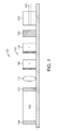
- FIG. 4 illustrates another embodiment of a tunable laser according to the present invention.
- FIG. 5A illustrates an embodiment of the tunable laser according to the present teaching that is similar to the tunable laser described in connection with FIG. 1 but that includes an integrated frequency selective device and optical phase retarder.
- FIG. 5B illustrates an embodiment of the tunable laser according to the present teaching that is similar to the tunable laser described in connection with FIG. 4 but that includes an integrated frequency selective device and optical phase retarder.
- FIG. 6A illustrates another embodiment of the tunable laser according to the present teaching that is similar to the tunable laser described in connection with FIG. 1 but that includes an integrated optical phase retarder and a partially reflecting mirror in a single laser facet configuration.
- FIG. 6B illustrates another embodiment of the tunable laser according to the present teaching that is similar to the tunable laser described in connection with FIG. 4 but that includes an integrated optical phase retarder and a high reflectivity mirror in a dual laser facet configuration.
- FIG. 7A illustrates another embodiment of the tunable laser according to the present teaching that is similar to the tunable laser described in connection with FIG. 1 but that includes an integrated gain medium and optical phase retarder in a single laser facet configuration.
- FIG. 7B illustrates another embodiment of the tunable laser according to the present teaching that is similar to the tunable laser described in connection with FIG. 4 but that includes an integrated gain medium and optical phase retarder in a dual laser facet configuration.
- the present teaching relates to tunable lasers that use a frequency-selective and a phase-controlling feedback mechanism in various configurations.
- the present teaching is described in connection with a tunable laser comprising a semiconductor gain medium having a laser facet that forms one end of an optical cavity and a mirror at the other end of the optical cavity.
- the tunable laser of the present teaching is not limited to tunable lasers with semiconductor gain medium. Any type of gain medium can be used with the tunable laser of the present teaching.
- the tunable laser of the present teaching is not limited to tunable lasers with optical cavities formed by a laser facet. Any type of mirrors can be used with the tunable laser of the present teaching.
- the tunable laser includes a semiconductor gain medium, a thermally tunable frequency selector, and a thermally tunable phase retarder in an external cavity configuration.
- the thermally controlled frequency selector is a single element that can tune across an entire optical transmission communication band, or a subset thereof, such as the C- or L-bands.
- the thermally tunable optical phase retarder is a material that changes its optical path length with temperature.
- the thermally tunable frequency selector and the thermally tunable phase retarder can each have integrated resistive heaters. Many embodiments of the thermally tunable frequency selector and the thermally tunable phase retarder are relatively small in size and can be manufactured in large volume with high yield using well known semiconductor processes.
- the temperature controlled frequency selector and the temperature controlled phase retarder are integrated together in one single element. Also, the temperature controlled phase retarder can be integrated with one or both of the laser mirrors. In addition, the temperature controlled phase retarder can be integrated with the semiconductor gain media.
- FIG. 1 illustrates one embodiment of a tunable laser 100 according to the present invention.
- the tunable laser 100 is configured as a frequency-selective external optical cavity 102 that includes a high-reflectivity mirror 104 forming one end of the optical cavity 102 and a partially reflecting mirror forming a laser facet 106 on the other end of the optical cavity 102 .
- One feature of the embodiment of the tunable laser 100 shown in FIG. 1 is that using a single partially reflecting laser facet 106 provides for relatively easy alignment of the optical components.
- the tunable laser 100 shown in FIG. 1 is formed of discrete optical components.
- tunable lasers according to the present teaching can be fabricated in various configurations and by various means to construct a tunable laser that is fully integrated, partially integrated with some discrete components and some integrated components, or formed of all discrete devices.
- the tunable laser 100 includes a semiconductor gain medium 108 .
- a semiconductor gain medium 108 One skilled in the art will appreciate that numerous other types of optical gain medium can also be used.
- An output of a current source is electrically connected to the semiconductor gain medium 108 to provide power for generating the optical gain.
- the semiconductor gain medium 108 includes the high-reflectivity mirror 104 on a first end surface which forms one end of the optical cavity 102 .
- the second end surface of the semiconductor gain medium 108 has an antireflection coating 110 for passing the optical beam in both directions without being reflected into and out of the cavity 102 .
- a collimating lens 112 is positioned adjacent to the optical gain medium 108 to focus the optical beam into and out of the semiconductor gain medium 108 .
- An optical phase retarder 114 is positioned adjacent to the collimating lens 112 .
- the optical phase retarder 114 is a temperature controlled phase retarder 114 , such as a thermally-tunable phase retarder.
- the thermally-tunable phase retarder 114 can be a silicon chip positioned proximate to or in contact with a heater.
- Various types of heaters can be used with the optical phase retarder 114 of the present teaching.
- the heater can be a resistive heater integrated into the phase retarder 114 or in close proximity.
- the optical phase retarder 114 is a discrete element.
- the optical phase retarder 114 is integrated with a frequency selective device.
- the optical phase retarder 114 is integrated with the gain medium 108 .
- the optical phase retarder 114 is used to adjust the cavity mode so that the cavity mode lines up directly with the desired optical frequency.
- a frequency selective device 116 such as an optical filter, is positioned adjacent to the optical phase retarder 114 .
- the frequency selective device 116 is a thermally tunable optical filter.
- the frequency selective device 116 can be a thermally tunable Fabry-Perot optical filter that includes a single crystalline sheet resistance heater layer, a thin single crystalline (c-Si) silicon spacer layer (and numerous other types of spacer layers), and distributed Bragg reflectors having layers of dielectric materials.
- c-Si thin single crystalline
- the optical phase retarder 114 and the frequency selective device 116 can be integrated in many different ways.
- the optical phase retarder 114 and the frequency selective device 116 can comprise an integrated temperature controlled phase retarder and thermally tunable optical filter.
- the frequency selective device 116 and the optical phase retarder 114 can be position anywhere in the optical cavity.
- the frequency selective device 116 can be positioned adjacent to the collimating lens 112 and the optical phase retarder 114 can be positioned adjacent to the laser facet 106 .
- the partially reflecting mirror or laser facet 106 is positioned adjacent to the frequency selective device 116 in the optical path.
- the reflectivity of the laser facet 106 is chosen to provide the desired feedback into the optical cavity 102 .
- An optical fiber collimating lens 118 is positioned adjacent to the laser facet 106 .
- An input of an optical fiber 120 is positioned at the output of the collimating lens 118 .
- the elements of the tunable laser according to the present invention need to be accurately aligned in order to maximize the performance of the layer.
- Accurate alignment of the external cavity elements comprising the tunable laser 100 is important to ensure high coupling efficiency of light into and out of the gain medium 108 and into the optical fiber 120 .
- accurate alignment of the external cavity elements is important to maximize tuning efficiency of the frequency selective device 116 and the efficiency of the optical phase retarder 114 .
- accurate alignment of the external cavity elements is important to minimize back-reflection causing undesired cavity resonances.
- a method of operating the tunable laser 100 described in connection with FIG. 1 where both the optical phase retarder 114 and the frequency selective device 116 are thermally tunable is as follows.
- Current is applied to the gain media 108 so as to cause the tunable laser 100 to generate stimulated emission between the high-reflectivity mirror 104 and the partially-reflecting laser facet 106 .
- the frequency-selective external optical cavity 102 can support many optical modes that meet the phase-matching condition. One or more of these optical modes is selected by adjusting the tunable optical filter 116 .
- the tunable optical filter 116 is tuned in frequency by applying current to a resistive heater positioned proximate to or integrated with the tunable optical filter 116 .
- the resonant frequency of the tunable optical filter 116 is determined by calibrating the measured resonant frequency with the corresponding device temperature.
- the resonant frequency measurements can be made with a spectrometer.
- the temperature measurements can be made with a thermistor or other type of temperature sensor.
- a stand-alone thermistor can be positioned in thermal contact with the tunable optical filter 116 .
- a thermistor can be fabricated directly on the tunable optical filter 116 , which can provide a more accurate measurement of the local device temperature.
- the optical phase retarder 114 provides a small change in the optical path length of the optical cavity 102 of more than one-half of a wavelength in each direction of propagation, where the wavelength corresponds to the resonant frequency of the tunable optical filter 116 .
- the change in path length is impressed on the cavity by changing the temperature of the optical phase retarder 114 , which changes the refractive index of the optical material comprising the phase retarder or other device.
- the change in optical path length corresponds to a phase retardation of up to two pi radians so that the phase-matching condition of the optical cavity 102 is shifted from one cavity mode to the next cavity mode.
- a phase retardation greater than two pi radians may be required.
- FIGS. 2A-2C illustrates the operation of the tunable laser described in connection with FIG. 1 .
- FIG. 2A illustrates a gain profile 200 of the optical gain medium used in tunable lasers according to the present teaching with the optical cavity modes 202 superimposed onto the gain profile 200 .
- FIG. 2A illustrates the gain of a semiconductor amplifier suitable for use with tunable lasers according to the present teaching as a function of frequency with the optical cavity modes 202 superimposed onto the gain profile 200 as a function of frequency.
- FIG. 2B illustrates a gain profile 220 as a function of frequency and a filter response 222 of a tunable optical filter used in the tunable lasers according to the present teaching as a function of time showing cavity modes 224 and 224 ′ of the filter relative to the other cavity modes 226 .
- FIG. 2B shows that there are two cavity modes 224 , 224 ′ inside the filter response 222 .
- the center frequency of the tunable optical filter is chosen by adjusting the temperature of the tunable optical filter.
- FIG. 2C illustrates a gain profile 240 as a function of frequency and a filter response 242 of a tunable optical filter used in the tunable lasers according to the present teaching as a function of time showing the alignment of one specific cavity mode 244 to the center frequency of the tunable filter response.
- the alignment is achieved by adjusting the temperature of the temperature controlled phase retarder in the tunable laser.
- FIG. 3A illustrates one embodiment of a thermally tunable Fabry-Perot optical filter 300 that can be used in the tunable laser of the present teaching.
- the tunable optical filter 300 includes a single-crystalline silicon cavity 302 .
- the tunable optical filter 300 can include an amorphous silicon or various III-IV semiconductor material Fabry-Perot cavities.
- a first distributed Bragg reflector 304 is formed on a top surface of the single-crystalline silicon cavity 302 .
- a quarter-wavelength oxide layer 306 is formed on the bottom surface of the single-crystalline silicon cavity 302 by fusion bonding the two halves of the tunable optical filter 300 .
- a second distributed Bragg reflector 308 is formed on the bottom surface of the optional quarter wavelength oxide layer 306 .
- a single crystalline heater 310 is formed on the bottom of the second distributed Bragg reflector 308 . An electrical contact is made to the crystalline heater 310 .
- a glass substrate 312 is bonded to the single crystalline heater 310 .
- FIG. 3B illustrates another embodiment of a thermally tunable Fabry-Perot optical filter 350 that can be used in the tunable laser of the present teaching.
- the tunable optical filter 350 is similar to the tunable optical filter 300 that was described in connection with FIG. 3A .
- the tunable optical filter 350 includes a single-crystalline silicon cavity 352 .
- the tunable optical filter 350 can include an amorphous silicon or various III-IV semiconductor material Fabry-Perot cavities.
- a first 354 and second distributed Bragg reflector 356 are positioned directly adjacent to the single-crystalline silicon cavity 352 .
- the first distributed Bragg reflector 354 is formed on a top surface of the single-crystalline silicon cavity 352 .
- the second distributed Bragg reflector 356 is formed on a bottom surface of the single-crystalline silicon cavity 352 .
- a quarter wavelength oxide layer 358 is formed on the bottom surface of the second distributed Bragg reflector 356 by fusion bonding two halves of the tunable optical filter 350 .
- a single crystalline heater 360 is formed on the bottom of the quarter wavelength oxide layer 358 . An electrical contact is made to the crystalline heater 360 .
- a glass substrate 362 is bonded to the single crystalline heater 360 .
- the thermally tunable Fabry-Perot optical filters 300 , 350 are highly reliable.
- One feature of the thermally tunable Fabry-Perot optical filters 300 , 350 with single crystal cavities is that they have very low loss compared with amorphous silicon cavities in the wavelength ranges used for optical communications, such as 1550 nm.
- Another feature of the thermally tunable Fabry-Perot optical filters 300 , 350 with single crystal cavities is that they have high thermal stability.
- Another feature of the thermally tunable Fabry-Perot optical filters 300 , 350 with single crystal cavities is that they have a wide thermal tuning range due to their thermal stability.
- thermally tunable Fabry-Perot optical filters 300 , 350 with single crystal cavities is that thicknesses of the single crystalline silicon cavities can be achieved over a much greater range compared with amorphous silicon and III-V semiconductor material cavities that are used in other optical filters.
- the gain media 108 can be positioned away from the ends of the optical cavity 102 .
- the use of both facets of the gain medium 108 enables the coupling of higher optical power into the optical fiber 120 .
- the frequency selective device 116 and the optical phase retarder 114 can be positioned in various positions in the optical cavity 102 .
- the frequency selective device 116 and the optical phase retarder 114 can be separate or integrated devices.
- FIG. 4 illustrates another embodiment of a tunable laser 400 according to the present invention.
- the tunable laser 400 is configured as a frequency-selective external optical cavity 402 that includes a discrete high-reflectivity mirror 404 at one end of the optical cavity 402 and a single partially reflecting laser facet 406 at the other end of the optical cavity 402 .
- the tunable laser 400 includes an optical phase retarder 408 positioned adjacent to the high-reflectivity mirror 404 .
- the optical phase retarder 408 is a thermally-tunable phase retarder, such as a silicon chip positioned proximate to a resistive heater. The optical phase retarder 408 is used to adjust the optical cavity modes so that a cavity mode lines up directly with the desired optical frequency.
- a frequency selective device 410 such as an optical filter, is positioned adjacent to the optical phase retarder 408 .
- the frequency selective device 410 is a thermally tunable optical filter.
- the frequency selective device 410 can be a thermally tunable Fabry-Perot optical filter as described herein.
- the frequency selective device 410 and the optical phase retarder 408 comprise an integrated temperature controlled phase retarder and thermally tunable optical filter. Also, in various embodiments, the positions of the frequency selective device 410 and the optical phase retarder 408 are interchanged.
- the tunable laser 100 includes a semiconductor gain medium 412 .
- Collimating lenses 414 , 414 ′ can be positioned adjacent to one or both ends of the semiconductor gain media 412 to focus the optical beam into and out of one or both sides of the semiconductor gain medium 412 .
- An output of a current source is applied to the semiconductor gain medium 412 to provide power for generating the optical gain.
- the semiconductor gain medium 412 has an antireflection coating 416 on a first end surface positioned adjacent to the collimating lens 414 and the frequency selective device 410 .
- the reflectivity of the partially reflecting laser facet 406 is chosen to provide the desired feedback into the optical cavity 402 .
- An optical fiber collimating lens 418 is positioned adjacent to the partially reflecting laser facet 406 and the lens 414 ′.
- An input of an optical fiber 420 is positioned at the output of the collimating lens 414 ′.
- the collimating lens 414 ′ focuses the light into the input of the optical fiber 420 .
- FIGS. 5A and 5B illustrate other embodiments of the tunable laser according to the present teaching that include an integrated frequency selective device and optical phase retarder for single and dual laser facet configurations.
- the control of the frequency selective device and optical phase retarder is done via separate heating elements located on the respective sides of the integrated element. There is some heat diffusion through the integrated element, so the control of the frequency selective device and optical phase retarder are somewhat coupled. However, for integrated elements with sufficient optical path length, the temperature difference across the integrated element may be sufficient to control both phase and frequency.
- FIG. 5A illustrates an embodiment of the tunable laser according to the present teaching that is similar to the tunable laser 100 described in connection with FIG. 1 .
- the tunable laser 500 includes an integrated frequency selective device and optical phase retarder 502 that includes a first heater 504 positioned at the end of the optical phase retarder section and a second heater 506 positioned at the end of the frequency selective device section of the integrated frequency selective device and optical phase retarder 502 .
- FIG. 5B illustrates an embodiment of the tunable laser according to the present teaching that is similar to the tunable laser 400 described in connection with FIG. 4 .
- the tunable laser 550 includes an integrated frequency selective device and optical phase retarder 552 positioned between the high reflectivity mirror 404 and the lens 414 .
- the first heater 554 is positioned at the end of the optical phase retarder section and a second heater 556 is positioned at the end of the frequency selective device section of the integrated frequency selective device and optical phase retarder 552 .
- FIGS. 6A and 6B illustrate other embodiments of the tunable laser according to the present teaching that include an integrated phase retarder and mirror for single and dual laser facet configurations.
- the single laser facet configuration includes an integrated phase retarder and partially-reflecting mirror.
- the dual laser facet configuration includes an integrated phase retarder and high reflectivity mirror.
- the material used to form the mirrors can be chosen to be tolerant to temperature change provided by the heater.
- FIG. 6A illustrates an embodiment of the tunable laser according to the present teaching that is similar to the tunable laser 100 described in connection with FIG. 1 .
- the tunable laser 600 includes an integrated optical phase retarder and partially reflecting mirror 602 in a single laser facet configuration.
- the integrated device 602 includes an optical phase retarder section 604 with a heater 606 at one end and a partially reflecting mirror 608 at the other end.
- FIG. 6B illustrates an embodiment of the tunable laser according to the present teaching that is similar to the tunable laser 400 described in connection with FIG. 4 .
- the tunable laser 650 includes an integrated optical phase retarder and high reflectivity mirror 652 in a dual laser facet configuration.
- the integrated device 652 includes an optical phase retarder section 654 with a heater 656 at one end and a high reflectivity mirror 658 at the other end.
- FIGS. 7A and 7B illustrate other embodiments of the tunable laser according to the present teaching that include an integrated gain medium and optical phase retarder for single and dual laser facet configurations.
- the optical phase retarder and gain medium are controlled by applying an electrical current to each section of the integrated device.
- FIG. 7A illustrates an embodiment of the tunable laser according to the present teaching that is similar to the tunable laser 100 described in connection with FIG. 1 .
- the tunable laser 700 includes an integrated optical phase retarder and gain medium 702 in a single laser facet configuration.
- the integrated device 702 includes an optical phase retarder section 704 with an antireflection coating 708 at one end and a gain medium 706 with a high reflectivity coating 710 at the other end.
- FIG. 7B illustrates an embodiment of the tunable laser according to the present teaching that is similar to the tunable laser 400 described in connection with FIG. 4 .
- the tunable laser 750 includes an integrated optical phase retarder and gain medium 752 in a dual laser facet configuration.
- the integrated device 752 includes an optical phase retarder section 754 with an antireflection coating 756 at one end and a gain medium 758 with an anti-reflection coating 760 at the other end.
Abstract
Description
Claims (24)
Priority Applications (2)
| Application Number | Priority Date | Filing Date | Title |
|---|---|---|---|
| US13/372,549 US8670470B2 (en) | 2011-02-25 | 2012-02-14 | Tunable Laser |
| CN2012100438549A CN102651533A (en) | 2011-02-25 | 2012-02-24 | Tunable laser |
Applications Claiming Priority (2)
| Application Number | Priority Date | Filing Date | Title |
|---|---|---|---|
| US201161446514P | 2011-02-25 | 2011-02-25 | |
| US13/372,549 US8670470B2 (en) | 2011-02-25 | 2012-02-14 | Tunable Laser |
Publications (2)
| Publication Number | Publication Date |
|---|---|
| US20120219023A1 US20120219023A1 (en) | 2012-08-30 |
| US8670470B2 true US8670470B2 (en) | 2014-03-11 |
Family
ID=46718965
Family Applications (1)
| Application Number | Title | Priority Date | Filing Date |
|---|---|---|---|
| US13/372,549 Active US8670470B2 (en) | 2011-02-25 | 2012-02-14 | Tunable Laser |
Country Status (2)
| Country | Link |
|---|---|
| US (1) | US8670470B2 (en) |
| CN (1) | CN102651533A (en) |
Families Citing this family (11)
| Publication number | Priority date | Publication date | Assignee | Title |
|---|---|---|---|---|
| CN103887690B (en) * | 2012-12-20 | 2016-08-03 | 福州高意通讯有限公司 | A kind of two-frequency laser |
| US9251210B2 (en) | 2013-04-19 | 2016-02-02 | Oracle International Corporation | Caching external data sources for SQL processing |
| CN103311802A (en) * | 2013-05-31 | 2013-09-18 | 华为技术有限公司 | Wavelength-tunable laser output method and tunable laser device |
| GB2516679C (en) * | 2013-07-30 | 2019-08-28 | Rushmere Tech Limited | Optical source |
| KR20150114823A (en) * | 2014-04-02 | 2015-10-13 | 한국전자통신연구원 | Tunable External Cavity Laser |
| US10936616B2 (en) | 2014-06-09 | 2021-03-02 | Oracle International Corporation | Storage-side scanning on non-natively formatted data |
| US10019473B2 (en) | 2014-06-09 | 2018-07-10 | Oracle International Corporation | Accessing an external table in parallel to execute a query |
| CN105223654B (en) * | 2014-06-11 | 2019-02-01 | 上海诺基亚贝尔股份有限公司 | The method and apparatus that wavelength for hot tunable optic filter jumps |
| US9865640B2 (en) * | 2016-01-31 | 2018-01-09 | Tower Semiconductor Ltd. | Backside illuminated (BSI) CMOS image sensor (CIS) with a resonant cavity and a method for manufacturing the BSI CIS |
| GB2570440A (en) * | 2017-12-19 | 2019-07-31 | Rushmere Tech Limited | Optical source and method of assembling an optical source |
| US11906784B2 (en) | 2022-04-11 | 2024-02-20 | Nokia Solutions And Networks Oy | Turnable free space optical filters |
Citations (1)
| Publication number | Priority date | Publication date | Assignee | Title |
|---|---|---|---|---|
| US20050123008A1 (en) * | 2003-12-08 | 2005-06-09 | Daiber Andrew J. | Multiple input/output ECDL cavity length and filter temperature control |
Family Cites Families (6)
| Publication number | Priority date | Publication date | Assignee | Title |
|---|---|---|---|---|
| US6853654B2 (en) * | 1999-07-27 | 2005-02-08 | Intel Corporation | Tunable external cavity laser |
| CN100350683C (en) * | 2001-03-21 | 2007-11-21 | 英特尔公司 | Error signal generation system |
| US6901088B2 (en) * | 2001-07-06 | 2005-05-31 | Intel Corporation | External cavity laser apparatus with orthogonal tuning of laser wavelength and cavity optical pathlength |
| US6804278B2 (en) * | 2001-07-06 | 2004-10-12 | Intel Corporation | Evaluation and adjustment of laser losses according to voltage across gain medium |
| US6763047B2 (en) * | 2002-06-15 | 2004-07-13 | Intel Corporation | External cavity laser apparatus and methods |
| CN101814694B (en) * | 2010-04-28 | 2011-07-20 | 天津奇谱光电技术有限公司 | Tunable laser |
-
2012
- 2012-02-14 US US13/372,549 patent/US8670470B2/en active Active
- 2012-02-24 CN CN2012100438549A patent/CN102651533A/en active Pending
Patent Citations (1)
| Publication number | Priority date | Publication date | Assignee | Title |
|---|---|---|---|---|
| US20050123008A1 (en) * | 2003-12-08 | 2005-06-09 | Daiber Andrew J. | Multiple input/output ECDL cavity length and filter temperature control |
Also Published As
| Publication number | Publication date |
|---|---|
| CN102651533A (en) | 2012-08-29 |
| US20120219023A1 (en) | 2012-08-30 |
Similar Documents
| Publication | Publication Date | Title |
|---|---|---|
| US8670470B2 (en) | Tunable Laser | |
| US6393185B1 (en) | Differential waveguide pair | |
| US6243517B1 (en) | Channel-switched cross-connect | |
| US8831049B2 (en) | Tunable optical system with hybrid integrated laser | |
| US6324204B1 (en) | Channel-switched tunable laser for DWDM communications | |
| EP1156563B1 (en) | Laser wavelength stabilisation system for optical commmunication | |
| TWI251393B (en) | Tunable laser | |
| US6101210A (en) | External cavity laser | |
| US6879619B1 (en) | Method and apparatus for filtering an optical beam | |
| US20030214700A1 (en) | Tunable filter | |
| CN103907248A (en) | Thermo-optically tunable laser system | |
| WO2011120246A1 (en) | Tunable laser | |
| WO2011134177A1 (en) | Tunable laser | |
| US7106920B2 (en) | Laser array for generating stable multi-wavelength laser outputs | |
| WO2015089871A1 (en) | Wavelength tunable external-cavity laser | |
| US6934313B1 (en) | Method of making channel-aligned resonator devices | |
| JP2003124566A (en) | Semiconductor laser control module and optical system | |
| CN102356524B (en) | Hybrid integrated tuneable laser | |
| US6507593B1 (en) | Step-tunable external-cavity surface-emitting semiconductor laser | |
| US20050276303A1 (en) | External Cavity Laser | |
| US20200412093A1 (en) | External-cavity quantum cascade laser | |
| WO2019122877A1 (en) | Optical source and method of assembling an optical source | |
| US9407061B2 (en) | Tunable light source | |
| US6959023B1 (en) | Laser with reflective etalon tuning element | |
| EP1364432A2 (en) | Optical transmitter comprising a stepwise tunable laser |
Legal Events
| Date | Code | Title | Description |
|---|---|---|---|
| AS | Assignment |
Owner name: PHOTOP AEGIS, INC., MASSACHUSETTS Free format text: CHANGE OF NAME;ASSIGNOR:AEGIS LIGHTWAVE, INC.;REEL/FRAME:030452/0216 Effective date: 20130104 |
|
| STCF | Information on status: patent grant |
Free format text: PATENTED CASE |
|
| AS | Assignment |
Owner name: II-VI PHOTONICS, (US) INC., MASSACHUSETTS Free format text: CHANGE OF NAME;ASSIGNOR:PHOTOP AEGIS, INC.;REEL/FRAME:032835/0420 Effective date: 20140228 |
|
| MAFP | Maintenance fee payment |
Free format text: PAYMENT OF MAINTENANCE FEE, 4TH YEAR, LARGE ENTITY (ORIGINAL EVENT CODE: M1551) Year of fee payment: 4 |
|
| AS | Assignment |
Owner name: BANK OF AMERICA, N.A., AS ADMINISTRATIVE AGENT, NO Free format text: NOTICE OF GRANT OF SECURITY INTEREST IN PATENTS;ASSIGNORS:II-VI INCORPORATED;MARLOW INDUSTRIES, INC.;EPIWORKS, INC.;AND OTHERS;REEL/FRAME:050484/0204 Effective date: 20190924 Owner name: BANK OF AMERICA, N.A., AS ADMINISTRATIVE AGENT, NORTH CAROLINA Free format text: NOTICE OF GRANT OF SECURITY INTEREST IN PATENTS;ASSIGNORS:II-VI INCORPORATED;MARLOW INDUSTRIES, INC.;EPIWORKS, INC.;AND OTHERS;REEL/FRAME:050484/0204 Effective date: 20190924 |
|
| MAFP | Maintenance fee payment |
Free format text: PAYMENT OF MAINTENANCE FEE, 8TH YEAR, LARGE ENTITY (ORIGINAL EVENT CODE: M1552); ENTITY STATUS OF PATENT OWNER: LARGE ENTITY Year of fee payment: 8 |
|
| AS | Assignment |
Owner name: II-VI DELAWARE, INC., DELAWARE Free format text: ASSIGNMENT OF ASSIGNORS INTEREST;ASSIGNOR:II-VI PHOTONICS, (US) INC.;REEL/FRAME:060333/0742 Effective date: 20220627 |
|
| AS | Assignment |
Owner name: JPMORGAN CHASE BANK, N.A., AS COLLATERAL AGENT, NEW YORK Free format text: SECURITY INTEREST;ASSIGNORS:II-VI INCORPORATED;II-VI DELAWARE, INC.;M CUBED TECHNOLOGIES, INC.;AND OTHERS;REEL/FRAME:060562/0254 Effective date: 20220701 |
|
| AS | Assignment |
Owner name: PHOTOP TECHNOLOGIES, INC., CALIFORNIA Free format text: PATENT RELEASE AND REASSIGNMENT;ASSIGNOR:BANK OF AMERICA, N.A., AS ADMINISTRATIVE AGENT;REEL/FRAME:060574/0001 Effective date: 20220701 Owner name: II-VI OPTOELECTRONIC DEVICES, INC., NEW JERSEY Free format text: PATENT RELEASE AND REASSIGNMENT;ASSIGNOR:BANK OF AMERICA, N.A., AS ADMINISTRATIVE AGENT;REEL/FRAME:060574/0001 Effective date: 20220701 Owner name: II-VI DELAWARE, INC., PENNSYLVANIA Free format text: PATENT RELEASE AND REASSIGNMENT;ASSIGNOR:BANK OF AMERICA, N.A., AS ADMINISTRATIVE AGENT;REEL/FRAME:060574/0001 Effective date: 20220701 Owner name: II-VI PHOTONICS (US), INC., MASSACHUSETTS Free format text: PATENT RELEASE AND REASSIGNMENT;ASSIGNOR:BANK OF AMERICA, N.A., AS ADMINISTRATIVE AGENT;REEL/FRAME:060574/0001 Effective date: 20220701 Owner name: M CUBED TECHNOLOGIES, INC., CONNECTICUT Free format text: PATENT RELEASE AND REASSIGNMENT;ASSIGNOR:BANK OF AMERICA, N.A., AS ADMINISTRATIVE AGENT;REEL/FRAME:060574/0001 Effective date: 20220701 Owner name: II-VI OPTICAL SYSTEMS, INC., CALIFORNIA Free format text: PATENT RELEASE AND REASSIGNMENT;ASSIGNOR:BANK OF AMERICA, N.A., AS ADMINISTRATIVE AGENT;REEL/FRAME:060574/0001 Effective date: 20220701 Owner name: FINISAR CORPORATION, CALIFORNIA Free format text: PATENT RELEASE AND REASSIGNMENT;ASSIGNOR:BANK OF AMERICA, N.A., AS ADMINISTRATIVE AGENT;REEL/FRAME:060574/0001 Effective date: 20220701 Owner name: OPTIUM CORPORATION, CALIFORNIA Free format text: PATENT RELEASE AND REASSIGNMENT;ASSIGNOR:BANK OF AMERICA, N.A., AS ADMINISTRATIVE AGENT;REEL/FRAME:060574/0001 Effective date: 20220701 Owner name: COADNA PHOTONICS, INC., PENNSYLVANIA Free format text: PATENT RELEASE AND REASSIGNMENT;ASSIGNOR:BANK OF AMERICA, N.A., AS ADMINISTRATIVE AGENT;REEL/FRAME:060574/0001 Effective date: 20220701 Owner name: KAILIGHT PHOTONICS, INC., CALIFORNIA Free format text: PATENT RELEASE AND REASSIGNMENT;ASSIGNOR:BANK OF AMERICA, N.A., AS ADMINISTRATIVE AGENT;REEL/FRAME:060574/0001 Effective date: 20220701 Owner name: LIGHTSMYTH TECHNOLOGIES, INC., OREGON Free format text: PATENT RELEASE AND REASSIGNMENT;ASSIGNOR:BANK OF AMERICA, N.A., AS ADMINISTRATIVE AGENT;REEL/FRAME:060574/0001 Effective date: 20220701 Owner name: EPIWORKS, INC., ILLINOIS Free format text: PATENT RELEASE AND REASSIGNMENT;ASSIGNOR:BANK OF AMERICA, N.A., AS ADMINISTRATIVE AGENT;REEL/FRAME:060574/0001 Effective date: 20220701 Owner name: MARLOW INDUSTRIES, INC., TEXAS Free format text: PATENT RELEASE AND REASSIGNMENT;ASSIGNOR:BANK OF AMERICA, N.A., AS ADMINISTRATIVE AGENT;REEL/FRAME:060574/0001 Effective date: 20220701 Owner name: II-VI INCORPORATED, PENNSYLVANIA Free format text: PATENT RELEASE AND REASSIGNMENT;ASSIGNOR:BANK OF AMERICA, N.A., AS ADMINISTRATIVE AGENT;REEL/FRAME:060574/0001 Effective date: 20220701 |