US8625973B2 - Method and apparatus for operating a video system - Google Patents
Method and apparatus for operating a video system Download PDFInfo
- Publication number
- US8625973B2 US8625973B2 US12/915,941 US91594110A US8625973B2 US 8625973 B2 US8625973 B2 US 8625973B2 US 91594110 A US91594110 A US 91594110A US 8625973 B2 US8625973 B2 US 8625973B2
- Authority
- US
- United States
- Prior art keywords
- frames
- video
- scene
- subset
- view
- Prior art date
- Legal status (The legal status is an assumption and is not a legal conclusion. Google has not performed a legal analysis and makes no representation as to the accuracy of the status listed.)
- Active, expires
Links
Images


Classifications
-
- H—ELECTRICITY
- H04—ELECTRIC COMMUNICATION TECHNIQUE
- H04N—PICTORIAL COMMUNICATION, e.g. TELEVISION
- H04N7/00—Television systems
- H04N7/18—Closed-circuit television [CCTV] systems, i.e. systems in which the video signal is not broadcast
- H04N7/181—Closed-circuit television [CCTV] systems, i.e. systems in which the video signal is not broadcast for receiving images from a plurality of remote sources
Definitions
- a method for operating a video system to generate and store encoded video comprising a plurality of key frames and a plurality of delta frames includes capturing video data comprising a plurality of frames of a scene, and selecting a fundamental view of at least a portion of the scene contained in the plurality of frames.
- the method also includes generating the plurality of key frames from a first subset of the plurality of frames and the fundamental view of at least the portion of the scene, generating the plurality of delta frames from a second subset of the plurality of frames and the plurality of key frames, and transferring the encoded video for delivery to storage.
- a video system to generate and store encoded video comprising a plurality of key frames and a plurality of delta frames includes a video capture device configured to capture video data comprising a plurality of frames of a scene, a memory configured to store the encoded video, and a video processor coupled with the video capture device and the memory.
- the video processor is configured to select a fundamental view of at least a portion of the scene contained in the plurality of frames, and generate the plurality of key frames from a first subset of the plurality of frames and the fundamental view of at least the portion of the scene.
- the video processor is also configured to generate the plurality of delta frames from a second subset of the plurality of frames and the plurality of key frames, and transfer the encoded video to the memory.
- FIG. 1 illustrates a block diagram of an example of a video system.
- FIG. 2 illustrates a block diagram of an example of a video source.
- FIG. 3 illustrates a block diagram of an example of a video processing system.
- FIG. 4 illustrates a block diagram of an example of a video system.
- FIG. 5 illustrates an example of a plurality of frames of a scene.
- FIG. 6 illustrates an example fundamental view of a scene.
- FIG. 7 illustrates a diagram of memory containing example encoded video data.
- FIG. 8 illustrates a diagram of memory containing example encoded video data.
- FIG. 9 illustrates an example view of a scene including a plurality of frames.
- FIG. 10 illustrates a diagram of memory containing example encoded video data.
- FIG. 11 illustrates a flow chart of a method of encoding video data.
- the encoder always has the choice of using intra-encoding if the encoder is unable to find a suitable motion vector. Therefore, encoding the initial frame of a GOP using this approach should not create results that are worse than standard key frame encoding.
- Some macroblocks within the reference image could be flagged to indicate that the encoder should always use intra-encoding for that macroblock. For example, macroblocks in regions of the camera view that have constant activity might use that flag.
- the encoder could bypass motion vector searching and use the following simpler method. Encode each macroblock using two approaches and retain the best (smallest) of the two encoded results:
- the encoder can skip the macroblock entirely.
- the decoder would simply copy the macroblock from the master reference image.
- Video system 100 includes video source 102 , video processing system 104 , and video storage system 106 .
- Video source 102 is coupled to video processing system 104
- video processing system 104 is coupled to video storage system 106 .
- the connections between the elements of video system 100 may use various communication media, such as air, metal, optical fiber, or some other signal propagation path—including combinations thereof. They may be direct links, or they might include various intermediate components, systems, and networks.
- a large number of video sources may all communicate with video processing system 104 , this results in bandwidth concerns as video processing system 104 may have an input port incapable of receiving full resolution, real time video from all of the video sources.
- An example of such a video source is illustrated in FIG. 2 .
- video source 102 captures video data comprising a plurality of frames of a scene and transfers the video data to video processing system 104 .
- Video processing system 104 selects a fundamental view of at least a portion of the scene contained in the plurality of frames. This portion of the scene may include one or more macroblocks of the scene. A portion of the scene may be selected for inclusion in the fundamental view based on the most common content of the portion of the scene as illustrated in FIGS. 5 and 6 .
- Video processing system 104 then generates a plurality of key frames from a first subset of the plurality of frames and the fundamental view of at least a portion of the scene. Video processing system 104 then generates a plurality of delta frames from a second subset of the plurality of frames and the plurality of key frames. For example, video processing system 104 may break the incoming video data into a plurality of groups of pictures (or groups of frames). The first frame of each group of frames may be selected for encoding as a key frame, while the remaining frames of each group of frames may be selected for encoding as delta frames.
- Key frames are encoded based on the fundamental view and portions of the key frame substantially similar to corresponding portions of the fundamental view may be encoded as pointers to the particular portion of the fundamental view instead of intra-encoding the portion.
- key frames which reference portions of the fundamental view will be smaller in memory size than key frames which include intra-encoding of the entire frame.
- each portion of the scene would have a lot of frames capturing the background a few frames capturing people.
- the most common content of each portion of the scene would then most likely contain just the background and no people.
- Video processing system 104 generates a fundamental view from the most common content captured in each portion of the scene.
- the frames capturing the background would be much more common than the frames capturing people, and the fundamental view would contain the background without any people.
- FIG. 2 is a block diagram of an example of a video source 200 , such as video source 102 from FIG. 1 .
- Video source 200 includes lens 202 , sensor 204 , processor 206 , memory 208 , and communication interface 210 .
- Lens 202 is configured to focus an image of a scene on sensor 204 .
- Lens 202 may be any type of lens, pinhole, zone plate, or the like able to focus an image on sensor 204 .
- Sensor 204 then digitally captures video of the scene and passes the video images to processor 206 .
- Processor 206 is configured to store some or all of the video in memory 208 , process the video, and send the processed video to external devices 212 through communication interface 210 .
- external devices 212 include video processing system 104 and video storage system 106 .
- video source 200 captures video data comprising a plurality of frames of a scene.
- Lens 202 and sensor 204 capture the video data and transfer the video data to processor 206 .
- Processor 206 selects a fundamental view of at least a portion of the scene contained in the plurality of frames.
- Processor 206 generates a plurality of key frames from a first subset of the plurality of frames and the fundamental view of at least a portion of the scene.
- Processor 206 also generates a plurality of delta frames from a second subset of the plurality of frames, the plurality of key frames, and preceding delta frames. For example, in a scene having a background with a number of people walking past, each portion of the scene would have a lot of frames capturing the background a few frames capturing people.
- Processor 206 then generates a fundamental view from the most common content captured in each portion of the scene.
- Other examples may use criteria other than the most common content for determining which portions of the scene to include in the fundamental view. For example, some embodiments may determine how long a scene has been unchanged. In this example, the portions of the scene capturing the background would be much more common than the frames capturing people, and the fundamental view would contain the background without any people.
- Video processing system 300 includes communication interface 311 , and processing system 301 .
- Processing system 301 is linked to communication interface 311 through a bus.
- Processing system 301 includes 302 and memory devices 303 that store operating software.
- Communication interface 311 includes network interface 312 , input ports 313 , and output ports 314 .
- Communication interface 311 includes components that communicate over communication links, such as network cards, ports, RF transceivers, processing circuitry and software, or some other communication devices.
- Communication interface 311 may be configured to communicate over metallic, wireless, or optical links.
- Communication interface 311 may be configured to use TDM, IP, Ethernet, optical networking, wireless protocols, communication signaling, or some other communication format—including combinations thereof.
- Network interface 312 is configured to connect to external devices over network 315 .
- these network devices may include video sources and video storage systems as illustrated in FIGS. 1 and 4 .
- Input ports 313 are configured to connect to input devices 316 such as a keyboard, mouse, or other user input devices.
- Output ports 314 are configured to connect to output devices 317 such as a display, a printer, or other output devices.
- Processor 302 includes microprocessor and other circuitry that retrieves and executes operating software from memory devices 303 .
- Memory devices 303 include random access memory (RAM) 304 , read only memory (ROM) 305 , a hard drive 306 , and any other memory apparatus.
- Operating software includes computer programs, firmware, or some other form of machine-readable processing instructions.
- operating software includes operating system 307 , applications 308 , modules 309 , and data 310 . Operating software may include other software or data as required by any specific embodiment.
- operating software directs processing system 301 to operate video processing system 300 as described herein.
- one or more video sources capture video data comprising a plurality of frames of a scene.
- This video data is transferred to processing system 301 through input ports 313 and communication interface 311 .
- Processor 302 selects a fundamental view of at least a portion of the scene contained in the plurality of frames.
- Processor 302 generates a plurality of key frames from a first subset of the plurality of frames and the fundamental view of at least a portion of the scene.
- Processor 302 also generates a plurality of delta frames from a second subset of the plurality of frames, the plurality of key frames, and preceding delta frames. For example, in a scene having a background with a number of people walking past, each portion of the scene would have a lot of frames capturing the background a few frames capturing people.
- Processor 302 then generates a fundamental view from the most common content (or other criteria) captured in each macroblock.
- the frames capturing the background would be much more common than the frames capturing people, and the fundamental view would contain the background without any people.
- FIG. 4 illustrates a block diagram of an example of a video system 400 .
- Video system 400 includes video source 1 406 , video source N 408 , video processing system 410 , and video storage system 412 .
- Video source 1 406 is configured to capture video of scene 1 402
- video source N 408 is configured to capture video of scene N 404 .
- Video source 1 406 and video source N 408 are coupled to video processing system 410
- video processing system 410 is coupled to video storage system 412 .
- the connections between the elements of video system 400 may use various communication media, such as air, metal, optical fiber, or some other signal propagation path—including combinations thereof. They may be direct links, or they might include various intermediate components, systems, and networks.
- a large number of video sources may all communicate with video processing system 410 , this results in bandwidth concerns as video processing system 410 may have an input port incapable of receiving full resolution, real time video from all of the video sources.
- An example of such a video source is illustrated in FIG. 2 .
- the video sources may transfer the raw video data to video processing system 410 for creating fundamental views for the video data and storage in video storage 412 .
- FIG. 5 illustrates an example of a plurality of frames of a scene.
- four frames 500 , 502 , 504 , and 506 of a scene are illustrated in FIGS. 5 ( a ), ( b ), ( c ), and ( d ).
- the scene is divided into four portions (or macroblocks).
- the upper left portion of each frame contains an unchanging view of a rectangular block. Thus, the most common view of the upper left portion of the scene is the view of the rectangular block.
- each frame contains a changing view of a cylinder.
- Frames 500 and 502 contain identical views of the cylinder, while frames 504 and 506 contain different views of the cylinder. Thus, frames 500 and 502 contain the most common view of the cylinder in the upper right portion of the scene.
- each frame contains a changing view of a rectangular box.
- Frames 500 , 504 , and 506 contain identical views of the rectangular box, while frame 502 contains an end view of the rectangular box.
- frames 500 , 504 , and 506 contain the most common view of the rectangular box in the lower right portion of the scene.
- each frame contains a changing view of an L-shaped rod.
- Frames 500 , 502 , 504 , and 506 each contain a different view of the L-shaped rod. Thus, in this portion of the scene there is no most common view of the L-shaped rod in the lower left portion of the scene.
- FIG. 6 illustrates an example fundamental view of the scene from FIG. 5 .
- a fundamental view 600 is assembled from the most common views of the portions of the scene illustrated in FIG. 5 .
- the upper left portion of the fundamental view 600 contains a view of the rectangular box as captured in any of frames 500 , 502 , 504 , or 506 .
- the upper right portion of the fundamental view 600 contains a view of the cylinder as captured in either of frames 500 or 502 .
- the lower right portion of the fundamental view 600 contains a view of the rectangular box as captured in any of frames 500 , 504 , or 506 . Since there was no most common view of the lower left portion of the scene this portion is flagged in the fundamental view 600 .
- each key frame When key frames are encoded based upon fundamental view 600 , the upper left, upper right, and lower right portions of each key frame will contain any differences between the key frame portions and the corresponding portions of fundamental view 600 .
- the lower left portion of each key frame will be intra-encoded since there is no most common view of this portion of the scene.
- Other embodiments may use other criteria for deciding which frames to use in constructing fundamental view 600 .
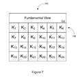
- FIG. 7 illustrates a diagram of memory containing example encoded video data.
- This example memory map 700 illustrates one possible method of encoding video data using a fundamental view 702 .
- fundamental view 702 is stored in a file in the memory and key frames 704 with respect to fundamental view 702 follow in the file.
- key frames 704 with respect to fundamental view 702 follow in the file.
- no delta frames are generated, and each frame of the video data is inter-encoded with respect to fundamental view 702 and stored in the file following fundamental view 702 .
- FIG. 8 illustrates a diagram of memory containing example encoded video data.
- This example memory map 800 illustrates another possible method of encoding video data using a fundamental view 702 , key frames 804 , 806 , 808 , and 810 , and a plurality of delta frames.
- the video data is divided into four groups of pictures 812 , 814 , 816 , and 818 . Each group of pictures includes a key frame and four delta frames.
- the first group of pictures 812 includes key frame key 1 804 and delta frames ⁇ 1 — 1 , ⁇ 1 — 2 , ⁇ 1 — 3 , and ⁇ 1 — 4 .
- the second group of pictures 814 includes key frame key 2 806 and delta frames ⁇ 2 — 1 , ⁇ 2 — 2 , ⁇ 2 — 3 , and ⁇ 2 — 4 .
- the third group of pictures 816 includes key frame key 3 808 and delta frames ⁇ 3 — 1 , ⁇ 3 — 2 , ⁇ 3 — 3 , and ⁇ 3 — 4 .
- the fourth group of pictures 818 includes key frame key 4 810 and delta frames ⁇ 4 — 1 , ⁇ 4 — 2 , ⁇ 4 — 3 , and ⁇ 4 — 4 .
- Each key frame is inter-encoded with respect to fundamental view 802
- each delta frame is inter-encoded with respect to its corresponding key frame and preceding delta frames.
- FIG. 9 illustrates an example view of a scene including a plurality of frames.
- a video capture device may not be stationary, but may pan over a scene. Typically these pans are continuously repeated and each pan generates a plurality of different views of the scene.
- a video capture device repeatedly pans scene 900 taking six different views of scene 900 during each pan cycle.
- scene 900 is covered by views 902 , 904 , 906 , 908 , 910 , and 910 .
- views 902 , 904 , 906 , 908 , 910 , and 910 are further divided into four portions. Since the panning motion of the video capture device is repeatable, a fundamental view may be constructed for each of views 902 , 904 , 906 , 908 , 910 , and 910 using the techniques illustrated in FIGS. 5 and 6 .
- FIG. 10 illustrates a diagram of memory containing example encoded video data.
- This example memory map 1000 illustrates one possible method of encoding video data received from a video capture device panning over scene 900 from FIG. 9 .
- Fundamental view FV 1 is generated for upper left view 902
- fundamental view FV 2 is generated for upper middle view 904
- fundamental view FV 3 is generated for upper right view 906
- fundamental view FV 4 is generated for lower left view 908
- fundamental view FV 5 is generated for lower middle view 910
- fundamental view FV 6 is generated for lower right view 912 .
- the fundamental views 1002 in memory map 1000 are the first six key frames K 1 , K 2 , K 3 , K 4 , K 5 , and K 6 1004 corresponding to each of the views.
- the delta frames 1006 , 1008 , and 1010 associated with each of the key frames.
- FIG. 11 illustrates a flow chart of a method of encoding video data.
- video data comprising a plurality of frames of a scene is captured, (operation 1100 ).
- a video processing system selects a fundamental view of at least a portion of the scene contained in the plurality of frames, (operation 1102 ).
- the video processing system generates a plurality of key frames from a first subset of the plurality of frames and the fundamental view of at least a portion of the scene, (operation 1104 ).
- the video processing system generates a plurality of delta frames from a second subset of the plurality of frames, the plurality of key frames, and preceding delta frames, (operation 1106 ).
- the video processing system transfers the resulting encoded video for delivery to storage, (operation 1108 ).
- Sophisticated video surveillance systems should not simply record video. Systems should be designed to gather optimal visual evidence that can be used to solve crimes or investigate incidents. Systems should use video analysis to identify specific types of activity and events that need to be recorded. The system should then tailor the recorded images to fit the activity—providing just the right level of detail (pixels per foot) and just the right image refresh rate for just long enough to capture the video of interest. The system should minimize the amount of space that is wasted storing images that will be of little value.
- the system should also store searchable metadata that describes the activity that was detected through video analysis.
- the system should enable users to leverage metadata to support rapid searching for activity that matches user-defined criteria without having to wait while the system decodes and analyzes images. All images should be analyzed one time when the images are originally captured (before compression) and the results of that analysis should be saved as searchable metadata.
- Modern video compression methods like H.264 involve detecting changes between images and then determining the optimal way to encode those changes.
- a large image is divided into a grid of small images called macroblocks, where a typical macroblock size is 8 ⁇ 8 pixels.
- macroblocks where a typical macroblock size is 8 ⁇ 8 pixels.
- the compression algorithm can choose between two methods of encoding the macroblock:
- the main characteristic that distinguishes a more effective compression algorithm from a less effective one is the degree to which the algorithm always finds the optimal motion vector for each macroblock to be encoded. If the amount of time and CPU power available for searching is unlimited, then the encoder can simply perform an exhaustive evaluation of all macroblocks in the reference image in order to identify the motion vector that will produce the smallest encoding. More advanced algorithms can take it one step further by using multiple reference images before and sometimes even after the image being encoded. More advanced algorithms can also select fractional pixel displacements for motion vectors (because moving objects won't always exactly align with macroblock boundaries).
- the ideal motion vector would be one that identifies the location of an identical macroblock in the reference image. That can occur when an object has moved within the camera view but otherwise the pixels representing the object have not changed. In general, if you know that an object is moving within the camera view, then the macroblocks that made up that same object in the reference image should be among the most promising motion vectors.
- Video analysis algorithms attempt to make sense out of the pixels in an image. These algorithms separate pixels into distinct objects (people, vehicles, etc.) and track the movement, behaviors, and interaction of objects.
- a method for operating a video source includes capturing first video data of a scene including a moving object, and processing the first video data to determine a motion vector for the moving object.
- the method also includes capturing second video data of the scene including the moving object, and compressing the second video data using the motion vector producing compressed second video data.
- portions of the image may contain information that is relevant to surveillance (moving people and vehicles) while the majority of the image may depict relatively static portions of the scene that closely match thousands of previous images from the same camera.
- an intelligent camera could encode images at variable resolution in order to provide the optimum resolution for the activity that is currently visible within the camera view.
- images could be displayed at low resolution initially.
- the low resolution macroblocks would be decoded first.
- Higher resolution macroblocks would be decoded and then scaled down to match the lower resolution macroblocks.
- the operator could select a portion of the image to be viewed in more detail.
- the application would determine if higher resolution macroblocks exist for that area, and would decode those macroblocks at full resolution.
- the application could automatically adjust the zoom level so that the selected area could be shown at full resolution—i.e. each pixel in the decoded image would correspond to one pixel in the displayed image.
- the application could highlight the portions of the image where higher resolution is available for display.
- the application could leverage metadata generated and stored during video encoding to highlight objects and specific types of activity in the displayed video. The operator could keep the overview image displayed in one window and use separate windows to display regions of interest at higher resolution.
- a method for operating a video source includes capturing video data of a scene, and processing the video data to determine an area of interest within the scene.
- the method also includes dividing the video data into macroblocks, determining the identity of the macroblocks including the area of interest, and encoding the macroblocks including the area of interest at a first resolution.
- the method further includes encoding the remaining macroblocks at a second resolution, wherein the first resolution is greater than the second resolution.
- a system such as that illustrated in FIG. 1
- uses video analysis to generate metadata during video encoding that metadata can support rapid scanning and searching for specific types of activity. For example, an operator might want to review video of a doorway and see every person that went through that door during a period of time. If the metadata contains a history of the times at which the camera captured forensic detail of a new person arriving in the scene, then the application could leverage the metadata to quickly display images of each person. Searching metadata would be many times faster (and more efficient with system resources) than decoding and analyzing video images to detect activity. For example, what if only one person goes through that door on average in a 10 hour period? Instead of decoding and analyzing 10 hours worth of video images to find the next event of interest, the system might only need to search through a few kilobytes of metadata.
- a method for operating a video source includes capturing video data of a scene, detecting an event within the video data, and placing an event timestamp including the date and time of the event in metadata corresponding to the video data.
- Intelligent cameras should capture and analyze images at the maximum frame rate available from the camera, and then based on an analysis of the activity the camera should decide which images need to be retained. Since the camera will not store images at a consistent frame rate, each image should include its own timestamp with millisecond precision.
- a method for operating a video source includes capturing video data comprising a plurality of frames of a scene, and identifying a first frame from the plurality of frames that includes a first aspect of an activity occurring within the scene. The method also includes subsequent to identifying the first frame, identifying at least a second frame from the plurality of frames that includes a second aspect of the activity occurring within the scene, and transferring the first frame and the second frame for delivery to storage.
- a Group of Pictures or GOP is a sequence of images consisting of a key frame followed by the delta frames that depend on that key frame.
- the number of images in a GOP is the key frame interval. For example, if the key frame interval is 32, that means one out of every 32 images is a key frame.
- an intelligent encoding algorithm could produce better results by selecting the optimum number of images to include in each GOP.
- P-Frames will be small because very few macroblocks need to be encoded for each new image.
- an intelligent camera such as that illustrated in FIG. 2 , can keep the video data rate as low as possible by continuing to extend the current GOP instead of encoding a key frame to start a new GOP.
- the encoder should only encode a key frame to start a new GOP when there is a reason for doing that—the encoder should not adhere to a fixed key frame interval. Following are valid reasons for starting a new GOP:
- a method for operating a video source includes capturing video data of a scene comprising a plurality of frames, opening a file for the video data, and storing a key frame in the file corresponding to a first of the plurality of frames. For each of the remaining plurality of frames, the method encodes the frame into macroblocks, determines a quantity of total macroblocks encoded since a last key frame was stored, and determines a quantity of macroblocks having errors since the last key frame was stored.
- the method also includes storing a new key frame when the quantity of total macroblocks encoded since the last key frame was stored exceeds a total encoded threshold, and storing a new key frame when the quantity of macroblocks having errors since the last key frame was stored exceeds an error threshold.
Landscapes
- Engineering & Computer Science (AREA)
- Multimedia (AREA)
- Signal Processing (AREA)
- Compression Or Coding Systems Of Tv Signals (AREA)
- Television Signal Processing For Recording (AREA)
Abstract
Description
-
- Identify the unchanging portions of the camera view. Save macroblocks (or portions of the scene) from one or more images to build up a reference image (or fundamental view). Each macroblock within the reference image (or fundamental view) should be the most common view of that portion of the picture.
- Each video file will start with a master reference image (fundamental view) that uses intra-encoding. This master reference image (fundamental view) is never displayed—it only serves as raw material for encoding other images.
- The frame at the beginning of each group of pictures (GOP) will be encoded using inter-encoding from the reference frame instead of the typical intra-encoding used for key frames. That is, calculate and store the differences between the reference image and the current image in exactly the same way a delta frame would be encoded. If there are a lot of closely matching macroblocks between the reference image and the image being encoded, then the resulting compressed image should be significantly smaller than a key frame.
-
- 1. Intra-encoding (the method normally used for all macroblocks in a key frame)
- 2. Inter-encoding relative to the master reference image, where the only motion vector evaluated is 0, 0 (no horizontal or vertical displacement).
-
- Inter-encoding means the compression algorithm finds a macroblock in the previous image (the reference image) that closely matches the macroblock to be encoded. The encoding for the new macroblock consists of a motion vector (which identifies the location of the referenced macroblock in the reference image) and a compressed representation of the difference between the encoded macroblock and the referenced macroblock.
- Intra-encoding means the macroblock is encoded without reference to any other macroblock. This approach can be used if the algorithm is unable to identify a motion vector that provides more optimal encoding.
-
- Capture an image at maximum resolution
- Identify the regions of the image that contain objects of interest where maximum resolution may provide value. Divide those regions into macroblocks and encode those macroblocks at full resolution. Macroblocks may be 8 pixels by 8 pixels in size in some examples, while other embodiments may user macroblocks of other sizes.
- Scale the image down to a lower resolution image—e.g. one half or one quarter the size of the original. Divide the lower resolution image into macroblocks and encode those macroblocks. If a macroblock in the lower resolution image corresponds completely to macroblocks already encoded at a higher resolution, that macroblock can be excluded from the lower resolution image.
-
- Overview detail is in the range of 20 to 30 pixels per foot. This is sufficient detail to track people and their movement but is not sufficient detail to recognize faces.
- Forensic detail is sufficient detail to serve as legal evidence in order to identify a particular person or read a license plate. Most sources recommend at least 40 pixels per foot to recognize faces and at least 60 pixels per foot to read license plates.
- High detail is sufficient to identify specific currency or casino chip values or small items being purchased at a point-of-sale terminal. High detail is 80 or more pixels per foot.
-
- If a video analysis algorithm detects that an original high resolution image includes a clear view of a person's face and the image provides at least 40 pixels per foot in the area where the face is detected, then the camera could retain full resolution for the macroblocks required to encode the image of the face. The camera could also generate metadata (where metadata is additional data stored separately from video images, describing the contents of the video images) to indicate that the image includes a face encoded with forensic detail.
- If a camera uses video analysis to identify and track individuals, then the camera could capture a limited number of images of each person's face at forensic detail. The camera could identify and eliminate duplicate images showing exactly the same viewing angle of the person's face, but could retain additional images if images are captured at different viewing angles as the person moves within the camera view.
- If a camera uses video analysis to identify license plates within the camera view, then the camera could retain an image of the license plate at forensic detail whenever that much detail becomes available. After an image has been captured at sufficient detail to read the license plate, there is no need for the camera to store additional images of the same license plate at forensic detail. Other images of the same vehicle should provide sufficient detail to see the make and model of the vehicle, the movement of the vehicle, and any visible information about the occupants of the vehicle.
- For a camera that views a point-of-sale terminal, the camera could retain high detail of items on the conveyor and of cash-handling activity when the cash drawer is open. The camera could retain forensic detail of customers, employees, and merchandise scanning and bagging activity. Since employees typically enter the scene and then remain for long periods, there would be no need for the camera to repeatedly capture forensic detail of the employee's face—the camera should only retain enough detail to positively identify the employee when they arrive on the scene. For any uninterrupted sequence of images of the same employee, the metadata should identify the images that contain forensic detail to identify that employee. The camera would retain overview detail during periods when there is no customer present, the cash drawer is closed, and there is no activity of any known significance.
-
- When there is very little activity, the camera may drop down to a very low image rate—one frame per second or less.
- To track normal movement of people walking through the camera view, a medium frame rate like 2-5 frames per second would be sufficient.
- If a person is detected running through the camera view or if a vehicle drives through the camera view at high speed, the camera may need to retain several consecutive images at the maximum image refresh rate to capture sufficient images of the fast-moving subject.
- For a camera that views a point-of-sale terminal, conveyor belt movement, merchandise scanning, and cash drawer activity would trigger higher frame rates, then the frame rate would slow down during low activity periods between transactions.
-
- I-Frames or intra-encoded frames are frames that can be decoded without referencing any other frame. I-Frames are also known as key frames.
- P-Frames or predicted frames are frames that require one or more reference frames during decoding. P-Frames are also known as delta frames because they store the differences between frames.
-
- Starting a new video file. Each video file must start with a key frame if a goal is to be able to decode all images in a video file without referencing any other video file.
- Random access performance. During video playback, long sequences of images in a GOP can decrease responsiveness when a user attempts to reposition to a particular image within a GOP. To decode any particular image, the decoder must start with the key frame at the beginning of the GOP and then decode each successive image until the target image has been decoded. The maximum time required for random access to a particular image will depend on the maximum number of macroblocks that must be decoded in order to decode the selected image. Every GOP requires decoding all of the macroblocks in the key frame. After that, the number of macroblocks to be decoded depends on the amount of activity (which determines the number of macroblocks per image) and the number of images. When there are few macroblocks per delta frame because of low activity, the GOP can be extended to a larger number of images without causing excessive random access times. Conversely, when there is very high activity it may be necessary to reduce the number of images in a GOP in order to maintain an acceptable maximum random access time.
- Accumulation of encoding errors. The encoding algorithm uses lossy compression when encoding the differences between images. Over time, the image that results from decoding successive delta frames can diverge from the image that would result from decoding a new key frame. If an intelligent camera has sufficient CPU power, it would be possible to encode a key frame for each captured image and then measure the encoding error of the image that would result from decoding the delta frames vs. the image that would result from decoding the key frame. To avoid having to transmit a new key frame, the encoder could select the macroblocks with the worst errors and encode and transmit those (using intra-encoding at the macroblock level if needed). If a large number of macroblocks have errors exceeding a threshold level, then it is time to end the current GOP and encode a new key frame.
Claims (18)
Priority Applications (1)
| Application Number | Priority Date | Filing Date | Title |
|---|---|---|---|
| US12/915,941 US8625973B2 (en) | 2009-10-30 | 2010-10-29 | Method and apparatus for operating a video system |
Applications Claiming Priority (7)
| Application Number | Priority Date | Filing Date | Title |
|---|---|---|---|
| US25650609P | 2009-10-30 | 2009-10-30 | |
| US25646309P | 2009-10-30 | 2009-10-30 | |
| US25653509P | 2009-10-30 | 2009-10-30 | |
| US25655309P | 2009-10-30 | 2009-10-30 | |
| US25656909P | 2009-10-30 | 2009-10-30 | |
| US25647609P | 2009-10-30 | 2009-10-30 | |
| US12/915,941 US8625973B2 (en) | 2009-10-30 | 2010-10-29 | Method and apparatus for operating a video system |
Publications (2)
| Publication Number | Publication Date |
|---|---|
| US20110102634A1 US20110102634A1 (en) | 2011-05-05 |
| US8625973B2 true US8625973B2 (en) | 2014-01-07 |
Family
ID=43925028
Family Applications (2)
| Application Number | Title | Priority Date | Filing Date |
|---|---|---|---|
| US12/915,941 Active 2032-05-10 US8625973B2 (en) | 2009-10-30 | 2010-10-29 | Method and apparatus for operating a video system |
| US12/915,868 Active 2033-02-17 US8982209B2 (en) | 2009-10-30 | 2010-10-29 | Method and apparatus for operating a video system |
Family Applications After (1)
| Application Number | Title | Priority Date | Filing Date |
|---|---|---|---|
| US12/915,868 Active 2033-02-17 US8982209B2 (en) | 2009-10-30 | 2010-10-29 | Method and apparatus for operating a video system |
Country Status (1)
| Country | Link |
|---|---|
| US (2) | US8625973B2 (en) |
Cited By (1)
| Publication number | Priority date | Publication date | Assignee | Title |
|---|---|---|---|---|
| US11082719B2 (en) | 2017-07-03 | 2021-08-03 | Nokia Technologies Oy | Apparatus, a method and a computer program for omnidirectional video |
Families Citing this family (15)
| Publication number | Priority date | Publication date | Assignee | Title |
|---|---|---|---|---|
| JP5561433B2 (en) * | 2011-05-24 | 2014-07-30 | 日産自動車株式会社 | Vehicle monitoring apparatus and vehicle monitoring method |
| JP5397433B2 (en) * | 2011-08-23 | 2014-01-22 | カシオ計算機株式会社 | Sales data processing apparatus and program |
| US8780233B2 (en) | 2011-12-19 | 2014-07-15 | Motorola Solutions, Inc. | Method and apparatus for maintaining a minimum pixel density across an object of interest |
| US10645345B2 (en) * | 2012-07-03 | 2020-05-05 | Verint Americas Inc. | System and method of video capture and search optimization |
| US8761448B1 (en) | 2012-12-13 | 2014-06-24 | Intel Corporation | Gesture pre-processing of video stream using a markered region |
| TW201429228A (en) * | 2013-01-14 | 2014-07-16 | Hon Hai Prec Ind Co Ltd | System and method for transmitting frames of a video |
| US9684881B2 (en) | 2013-06-26 | 2017-06-20 | Verint Americas Inc. | System and method of workforce optimization |
| KR102268597B1 (en) * | 2013-11-18 | 2021-06-23 | 한화테크윈 주식회사 | Appratus and method for processing image |
| KR102083931B1 (en) | 2014-01-21 | 2020-03-03 | 한화테크윈 주식회사 | Wide angle lens system |
| TWI586176B (en) * | 2014-10-01 | 2017-06-01 | 大猩猩科技股份有限公司 | Method and system for video synopsis from compressed video images |
| KR102310241B1 (en) | 2015-04-29 | 2021-10-08 | 삼성전자주식회사 | Source device, controlling method thereof, sink device and processing method for improving image quality thereof |
| US11159798B2 (en) | 2018-08-21 | 2021-10-26 | International Business Machines Corporation | Video compression using cognitive semantics object analysis |
| KR20210137049A (en) * | 2019-02-11 | 2021-11-17 | 643에이아이 엘티디. | Systems and methods for managing multiple autonomous vehicles |
| EP3745706B1 (en) * | 2019-05-29 | 2021-06-30 | Axis AB | System and method for video processing with picture stabilization and predictive compression |
| US11295660B2 (en) * | 2019-06-10 | 2022-04-05 | Ati Technologies Ulc | Frame replay for variable rate refresh display |
Citations (1)
| Publication number | Priority date | Publication date | Assignee | Title |
|---|---|---|---|---|
| US20090290855A1 (en) * | 2008-05-20 | 2009-11-26 | Francois-Xavier Kowalski | Apparatus And Method For Recording Video Data |
Family Cites Families (6)
| Publication number | Priority date | Publication date | Assignee | Title |
|---|---|---|---|---|
| US20050193425A1 (en) * | 2000-07-24 | 2005-09-01 | Sanghoon Sull | Delivery and presentation of content-relevant information associated with frames of audio-visual programs |
| JP4140202B2 (en) * | 2001-02-28 | 2008-08-27 | 三菱電機株式会社 | Moving object detection device |
| US20020131643A1 (en) * | 2001-03-13 | 2002-09-19 | Fels Sol Sidney | Local positioning system |
| US7893999B2 (en) * | 2006-05-22 | 2011-02-22 | Broadcom Corporation | Simultaneous video and sub-frame metadata capture system |
| US9239958B2 (en) * | 2007-11-09 | 2016-01-19 | The Nielsen Company (Us), Llc | Methods and apparatus to measure brand exposure in media streams |
| US8630497B2 (en) * | 2007-11-27 | 2014-01-14 | Intelliview Technologies Inc. | Analyzing a segment of video |
-
2010
- 2010-10-29 US US12/915,941 patent/US8625973B2/en active Active
- 2010-10-29 US US12/915,868 patent/US8982209B2/en active Active
Patent Citations (1)
| Publication number | Priority date | Publication date | Assignee | Title |
|---|---|---|---|---|
| US20090290855A1 (en) * | 2008-05-20 | 2009-11-26 | Francois-Xavier Kowalski | Apparatus And Method For Recording Video Data |
Cited By (1)
| Publication number | Priority date | Publication date | Assignee | Title |
|---|---|---|---|---|
| US11082719B2 (en) | 2017-07-03 | 2021-08-03 | Nokia Technologies Oy | Apparatus, a method and a computer program for omnidirectional video |
Also Published As
| Publication number | Publication date |
|---|---|
| US20110102593A1 (en) | 2011-05-05 |
| US8982209B2 (en) | 2015-03-17 |
| US20110102634A1 (en) | 2011-05-05 |
Similar Documents
| Publication | Publication Date | Title |
|---|---|---|
| US8625973B2 (en) | Method and apparatus for operating a video system | |
| EP2629523B1 (en) | Data compression for video | |
| US8902971B2 (en) | Video compression repository and model reuse | |
| CN100589567C (en) | The processing method of video data and memory device | |
| US9532069B2 (en) | Video compression repository and model reuse | |
| US9756348B2 (en) | Method, device and system for producing a merged digital video sequence | |
| AU2005272046B2 (en) | Method and apparatus for detecting motion in MPEG video streams | |
| JP6016332B2 (en) | Image processing apparatus and image processing method | |
| US11594254B2 (en) | Event/object-of-interest centric timelapse video generation on camera device with the assistance of neural network input | |
| US11869241B2 (en) | Person-of-interest centric timelapse video with AI input on home security camera to protect privacy | |
| US11263261B2 (en) | Method and system for characteristic-based video processing | |
| CN110717070A (en) | Video compression method and system for indoor monitoring scene | |
| KR101025133B1 (en) | Video surveillance system and video surveillance method thereof | |
| CA3057924A1 (en) | System and method to optimize the size of a video recording or video transmission by identifying and recording a region of interest in a higher definition than the rest of the image that is saved or transmitted in a lower definition format | |
| US20110129012A1 (en) | Video Data Compression | |
| US20220070453A1 (en) | Smart timelapse video to conserve bandwidth by reducing bit rate of video on a camera device with the assistance of neural network input | |
| US10051281B2 (en) | Video coding system with efficient processing of zooming transitions in video | |
| KR102042397B1 (en) | syntax-based method of producing heat-map for compressed video | |
| US20190208160A1 (en) | Systems and methods for intelligently recording video data streams | |
| Lacewell et al. | E2E Visual Analytics: Achieving> 10X Edge/Cloud Optimizations | |
| US20230127006A1 (en) | Hierarchical surveilance video compression repository | |
| He | Empowering Video Applications for Mobile Devices | |
| Singla et al. | A Review on HEVC Video Forensic Investigation under Compressed Domain | |
| JP2023028176A (en) | Management system | |
| JP2013168809A (en) | Image processing apparatus, image processing method, program, and storage medium |
Legal Events
| Date | Code | Title | Description |
|---|---|---|---|
| AS | Assignment |
Owner name: VERINT SYSTEMS INC., CALIFORNIA Free format text: ASSIGNMENT OF ASSIGNORS INTEREST;ASSIGNOR:PARDUE, WILLIAM DAVID;REEL/FRAME:025745/0483 Effective date: 20101029 |
|
| AS | Assignment |
Owner name: CREDIT SUISSE AG, CAYMAN ISLANDS BRANCH, AS COLLAT Free format text: GRANT OF SECURITY INTEREST IN PATENT RIGHTS;ASSIGNOR:VERINT SYSTEMS INC.;REEL/FRAME:031465/0314 Effective date: 20130918 |
|
| STCF | Information on status: patent grant |
Free format text: PATENTED CASE |
|
| AS | Assignment |
Owner name: VERINT AMERICAS INC., GEORGIA Free format text: ASSIGNMENT OF ASSIGNORS INTEREST;ASSIGNOR:VERINT SYSTEMS INC.;REEL/FRAME:037724/0507 Effective date: 20160129 |
|
| FPAY | Fee payment |
Year of fee payment: 4 |
|
| AS | Assignment |
Owner name: VERINT SYSTEMS INC., NEW YORK Free format text: RELEASE BY SECURED PARTY;ASSIGNOR:CREDIT SUISSE AG, CAYMAN ISLANDS BRANCH;REEL/FRAME:043066/0318 Effective date: 20170629 |
|
| AS | Assignment |
Owner name: JPMORGAN CHASE BANK, N.A., AS COLLATERAL AGENT, ILLINOIS Free format text: GRANT OF SECURITY INTEREST IN PATENT RIGHTS;ASSIGNOR:VERINT AMERICAS INC.;REEL/FRAME:043293/0567 Effective date: 20170629 Owner name: JPMORGAN CHASE BANK, N.A., AS COLLATERAL AGENT, IL Free format text: GRANT OF SECURITY INTEREST IN PATENT RIGHTS;ASSIGNOR:VERINT AMERICAS INC.;REEL/FRAME:043293/0567 Effective date: 20170629 |
|
| MAFP | Maintenance fee payment |
Free format text: PAYMENT OF MAINTENANCE FEE, 8TH YEAR, LARGE ENTITY (ORIGINAL EVENT CODE: M1552); ENTITY STATUS OF PATENT OWNER: LARGE ENTITY Year of fee payment: 8 |
|
| AS | Assignment |
Owner name: COGNYTE SOFTWARE LTD., ISRAEL Free format text: ASSIGNMENT OF ASSIGNORS INTEREST;ASSIGNOR:VERINT AMERICAS INC.;REEL/FRAME:057569/0475 Effective date: 20210201 |
|
| AS | Assignment |
Owner name: COGNYTE TECHNOLOGIES ISRAEL LTD, ISRAEL Free format text: CHANGE OF NAME;ASSIGNOR:VERINT SYSTEMS LTD.;REEL/FRAME:060751/0532 Effective date: 20201116 |
|
| AS | Assignment |
Owner name: COGNYTE TECHNOLOGIES ISRAEL LTD, ISRAEL Free format text: CHANGE OF NAME;ASSIGNOR:VERINT SYSTEMS LTD.;REEL/FRAME:059710/0742 Effective date: 20201116 |
|
| AS | Assignment |
Owner name: COGNYTE SOFTWARE LTD. (AS SUCCESSOR-IN-INTEREST TO VERINT AMERICAS INC.), ISRAEL Free format text: NOTICE OF PARTIAL TERMINATION AND RELEASE OF SECURITY INTEREST IN PATENT RIGHTS;ASSIGNOR:JPMORGAN CHASE BANK, N.A.;REEL/FRAME:061686/0615 Effective date: 20221014 |
|
| AS | Assignment |
Owner name: COGNYTE TECHNOLOGIES ISRAEL LTD, ISRAEL Free format text: ASSIGNMENT OF ASSIGNORS INTEREST;ASSIGNOR:COGNYTE SOFTWARE LTD.;REEL/FRAME:061675/0724 Effective date: 20221026 |