US8540349B2 - Printhead having isolated heater - Google Patents
Printhead having isolated heater Download PDFInfo
- Publication number
- US8540349B2 US8540349B2 US12/143,880 US14388008A US8540349B2 US 8540349 B2 US8540349 B2 US 8540349B2 US 14388008 A US14388008 A US 14388008A US 8540349 B2 US8540349 B2 US 8540349B2
- Authority
- US
- United States
- Prior art keywords
- heater
- cavity
- layer
- heating element
- dielectric layer
- Prior art date
- Legal status (The legal status is an assumption and is not a legal conclusion. Google has not performed a legal analysis and makes no representation as to the accuracy of the status listed.)
- Expired - Fee Related, expires
Links
- 239000007788 liquid Substances 0.000 claims abstract description 40
- 239000000758 substrate Substances 0.000 claims abstract description 35
- 238000010438 heat treatment Methods 0.000 claims abstract description 34
- 239000003989 dielectric material Substances 0.000 claims abstract description 17
- 239000003566 sealing material Substances 0.000 claims 1
- 239000010410 layer Substances 0.000 description 133
- 239000000976 ink Substances 0.000 description 54
- 238000000034 method Methods 0.000 description 20
- 239000000463 material Substances 0.000 description 16
- 239000011241 protective layer Substances 0.000 description 15
- 230000006911 nucleation Effects 0.000 description 11
- 238000010899 nucleation Methods 0.000 description 11
- 238000002161 passivation Methods 0.000 description 11
- 230000004888 barrier function Effects 0.000 description 9
- 238000013461 design Methods 0.000 description 9
- 230000015572 biosynthetic process Effects 0.000 description 8
- 238000000151 deposition Methods 0.000 description 8
- 238000004519 manufacturing process Methods 0.000 description 8
- 238000000059 patterning Methods 0.000 description 8
- 230000008569 process Effects 0.000 description 8
- 230000007480 spreading Effects 0.000 description 8
- 238000003892 spreading Methods 0.000 description 8
- 229910052581 Si3N4 Inorganic materials 0.000 description 7
- VYPSYNLAJGMNEJ-UHFFFAOYSA-N Silicium dioxide Chemical compound O=[Si]=O VYPSYNLAJGMNEJ-UHFFFAOYSA-N 0.000 description 7
- 229920002120 photoresistant polymer Polymers 0.000 description 7
- HQVNEWCFYHHQES-UHFFFAOYSA-N silicon nitride Chemical compound N12[Si]34N5[Si]62N3[Si]51N64 HQVNEWCFYHHQES-UHFFFAOYSA-N 0.000 description 7
- XUIMIQQOPSSXEZ-UHFFFAOYSA-N Silicon Chemical compound [Si] XUIMIQQOPSSXEZ-UHFFFAOYSA-N 0.000 description 6
- 230000008021 deposition Effects 0.000 description 6
- 230000004907 flux Effects 0.000 description 6
- 229910052710 silicon Inorganic materials 0.000 description 6
- 239000010703 silicon Substances 0.000 description 6
- BLIQUJLAJXRXSG-UHFFFAOYSA-N 1-benzyl-3-(trifluoromethyl)pyrrolidin-1-ium-3-carboxylate Chemical compound C1C(C(=O)O)(C(F)(F)F)CCN1CC1=CC=CC=C1 BLIQUJLAJXRXSG-UHFFFAOYSA-N 0.000 description 5
- 239000011229 interlayer Substances 0.000 description 5
- 229910052751 metal Inorganic materials 0.000 description 5
- 239000002184 metal Substances 0.000 description 5
- 238000000623 plasma-assisted chemical vapour deposition Methods 0.000 description 5
- 238000007639 printing Methods 0.000 description 5
- 238000012545 processing Methods 0.000 description 4
- 238000007789 sealing Methods 0.000 description 4
- 229910052782 aluminium Inorganic materials 0.000 description 3
- XAGFODPZIPBFFR-UHFFFAOYSA-N aluminium Chemical compound [Al] XAGFODPZIPBFFR-UHFFFAOYSA-N 0.000 description 3
- 238000007641 inkjet printing Methods 0.000 description 3
- 229910052814 silicon oxide Inorganic materials 0.000 description 3
- 229910052715 tantalum Inorganic materials 0.000 description 3
- GUVRBAGPIYLISA-UHFFFAOYSA-N tantalum atom Chemical compound [Ta] GUVRBAGPIYLISA-UHFFFAOYSA-N 0.000 description 3
- 238000012360 testing method Methods 0.000 description 3
- 238000012546 transfer Methods 0.000 description 3
- 238000009834 vaporization Methods 0.000 description 3
- 230000008016 vaporization Effects 0.000 description 3
- 229910021417 amorphous silicon Inorganic materials 0.000 description 2
- 238000009835 boiling Methods 0.000 description 2
- 238000011049 filling Methods 0.000 description 2
- 238000010304 firing Methods 0.000 description 2
- 239000012528 membrane Substances 0.000 description 2
- 238000005240 physical vapour deposition Methods 0.000 description 2
- HBMJWWWQQXIZIP-UHFFFAOYSA-N silicon carbide Chemical compound [Si+]#[C-] HBMJWWWQQXIZIP-UHFFFAOYSA-N 0.000 description 2
- 229910010271 silicon carbide Inorganic materials 0.000 description 2
- 235000012239 silicon dioxide Nutrition 0.000 description 2
- 239000000377 silicon dioxide Substances 0.000 description 2
- 229910002058 ternary alloy Inorganic materials 0.000 description 2
- XLYOFNOQVPJJNP-UHFFFAOYSA-N water Substances O XLYOFNOQVPJJNP-UHFFFAOYSA-N 0.000 description 2
- 229910000838 Al alloy Inorganic materials 0.000 description 1
- 239000004642 Polyimide Substances 0.000 description 1
- 229910018503 SF6 Inorganic materials 0.000 description 1
- 230000004913 activation Effects 0.000 description 1
- 238000003491 array Methods 0.000 description 1
- 230000009286 beneficial effect Effects 0.000 description 1
- 230000015556 catabolic process Effects 0.000 description 1
- 238000001816 cooling Methods 0.000 description 1
- 230000001186 cumulative effect Effects 0.000 description 1
- 230000003247 decreasing effect Effects 0.000 description 1
- 230000007547 defect Effects 0.000 description 1
- 238000006731 degradation reaction Methods 0.000 description 1
- 230000001627 detrimental effect Effects 0.000 description 1
- 238000005553 drilling Methods 0.000 description 1
- 229940079593 drug Drugs 0.000 description 1
- 230000000694 effects Effects 0.000 description 1
- 238000005530 etching Methods 0.000 description 1
- 230000003090 exacerbative effect Effects 0.000 description 1
- 238000002955 isolation Methods 0.000 description 1
- 230000007246 mechanism Effects 0.000 description 1
- 238000012986 modification Methods 0.000 description 1
- 230000004048 modification Effects 0.000 description 1
- 150000004767 nitrides Chemical class 0.000 description 1
- 238000013021 overheating Methods 0.000 description 1
- 229910021420 polycrystalline silicon Inorganic materials 0.000 description 1
- 229920001721 polyimide Polymers 0.000 description 1
- 229920000642 polymer Polymers 0.000 description 1
- 229920005591 polysilicon Polymers 0.000 description 1
- 230000001681 protective effect Effects 0.000 description 1
- 229910002059 quaternary alloy Inorganic materials 0.000 description 1
- 230000004044 response Effects 0.000 description 1
- 230000035939 shock Effects 0.000 description 1
- 238000005245 sintering Methods 0.000 description 1
- SFZCNBIFKDRMGX-UHFFFAOYSA-N sulfur hexafluoride Chemical compound FS(F)(F)(F)(F)F SFZCNBIFKDRMGX-UHFFFAOYSA-N 0.000 description 1
- 229960000909 sulfur hexafluoride Drugs 0.000 description 1
- 239000002470 thermal conductor Substances 0.000 description 1
Images


Classifications
-
- B—PERFORMING OPERATIONS; TRANSPORTING
- B41—PRINTING; LINING MACHINES; TYPEWRITERS; STAMPS
- B41J—TYPEWRITERS; SELECTIVE PRINTING MECHANISMS, i.e. MECHANISMS PRINTING OTHERWISE THAN FROM A FORME; CORRECTION OF TYPOGRAPHICAL ERRORS
- B41J2/00—Typewriters or selective printing mechanisms characterised by the printing or marking process for which they are designed
- B41J2/005—Typewriters or selective printing mechanisms characterised by the printing or marking process for which they are designed characterised by bringing liquid or particles selectively into contact with a printing material
- B41J2/01—Ink jet
- B41J2/135—Nozzles
- B41J2/14—Structure thereof only for on-demand ink jet heads
- B41J2/14016—Structure of bubble jet print heads
- B41J2/14088—Structure of heating means
- B41J2/14112—Resistive element
- B41J2/14129—Layer structure
-
- B—PERFORMING OPERATIONS; TRANSPORTING
- B41—PRINTING; LINING MACHINES; TYPEWRITERS; STAMPS
- B41J—TYPEWRITERS; SELECTIVE PRINTING MECHANISMS, i.e. MECHANISMS PRINTING OTHERWISE THAN FROM A FORME; CORRECTION OF TYPOGRAPHICAL ERRORS
- B41J2/00—Typewriters or selective printing mechanisms characterised by the printing or marking process for which they are designed
- B41J2/005—Typewriters or selective printing mechanisms characterised by the printing or marking process for which they are designed characterised by bringing liquid or particles selectively into contact with a printing material
- B41J2/01—Ink jet
- B41J2/135—Nozzles
- B41J2/14—Structure thereof only for on-demand ink jet heads
- B41J2/14016—Structure of bubble jet print heads
- B41J2/14088—Structure of heating means
- B41J2/14112—Resistive element
- B41J2/1412—Shape
-
- B—PERFORMING OPERATIONS; TRANSPORTING
- B41—PRINTING; LINING MACHINES; TYPEWRITERS; STAMPS
- B41J—TYPEWRITERS; SELECTIVE PRINTING MECHANISMS, i.e. MECHANISMS PRINTING OTHERWISE THAN FROM A FORME; CORRECTION OF TYPOGRAPHICAL ERRORS
- B41J2/00—Typewriters or selective printing mechanisms characterised by the printing or marking process for which they are designed
- B41J2/005—Typewriters or selective printing mechanisms characterised by the printing or marking process for which they are designed characterised by bringing liquid or particles selectively into contact with a printing material
- B41J2/01—Ink jet
- B41J2/135—Nozzles
- B41J2/16—Production of nozzles
- B41J2/1601—Production of bubble jet print heads
- B41J2/1603—Production of bubble jet print heads of the front shooter type
-
- B—PERFORMING OPERATIONS; TRANSPORTING
- B41—PRINTING; LINING MACHINES; TYPEWRITERS; STAMPS
- B41J—TYPEWRITERS; SELECTIVE PRINTING MECHANISMS, i.e. MECHANISMS PRINTING OTHERWISE THAN FROM A FORME; CORRECTION OF TYPOGRAPHICAL ERRORS
- B41J2/00—Typewriters or selective printing mechanisms characterised by the printing or marking process for which they are designed
- B41J2/005—Typewriters or selective printing mechanisms characterised by the printing or marking process for which they are designed characterised by bringing liquid or particles selectively into contact with a printing material
- B41J2/01—Ink jet
- B41J2/135—Nozzles
- B41J2/16—Production of nozzles
- B41J2/1621—Manufacturing processes
- B41J2/1626—Manufacturing processes etching
- B41J2/1628—Manufacturing processes etching dry etching
-
- B—PERFORMING OPERATIONS; TRANSPORTING
- B41—PRINTING; LINING MACHINES; TYPEWRITERS; STAMPS
- B41J—TYPEWRITERS; SELECTIVE PRINTING MECHANISMS, i.e. MECHANISMS PRINTING OTHERWISE THAN FROM A FORME; CORRECTION OF TYPOGRAPHICAL ERRORS
- B41J2/00—Typewriters or selective printing mechanisms characterised by the printing or marking process for which they are designed
- B41J2/005—Typewriters or selective printing mechanisms characterised by the printing or marking process for which they are designed characterised by bringing liquid or particles selectively into contact with a printing material
- B41J2/01—Ink jet
- B41J2/135—Nozzles
- B41J2/16—Production of nozzles
- B41J2/1621—Manufacturing processes
- B41J2/1637—Manufacturing processes molding
- B41J2/1639—Manufacturing processes molding sacrificial molding
-
- B—PERFORMING OPERATIONS; TRANSPORTING
- B41—PRINTING; LINING MACHINES; TYPEWRITERS; STAMPS
- B41J—TYPEWRITERS; SELECTIVE PRINTING MECHANISMS, i.e. MECHANISMS PRINTING OTHERWISE THAN FROM A FORME; CORRECTION OF TYPOGRAPHICAL ERRORS
- B41J2/00—Typewriters or selective printing mechanisms characterised by the printing or marking process for which they are designed
- B41J2/005—Typewriters or selective printing mechanisms characterised by the printing or marking process for which they are designed characterised by bringing liquid or particles selectively into contact with a printing material
- B41J2/01—Ink jet
- B41J2/135—Nozzles
- B41J2/16—Production of nozzles
- B41J2/1621—Manufacturing processes
- B41J2/164—Manufacturing processes thin film formation
- B41J2/1642—Manufacturing processes thin film formation thin film formation by CVD [chemical vapor deposition]
Definitions
- the present invention relates generally to micro heaters and their formation and, more particularly, to micro heaters used in ink jet devices and other liquid drop ejectors.
- Drop-on-demand (DOD) liquid emission devices have been used as ink printing devices in ink jet printing systems for many years. Early devices were based on piezoelectric actuators. A currently popular form of ink jet printing, thermal ink jet (or “thermal bubble jet”) devices use electrically resistive heaters to generate vapor bubbles which cause drop emission.
- thermal ink jet or “thermal bubble jet”
- the printhead used in a thermal inkjet system includes a nozzle plate having an array of ink jet nozzles above ink chambers. At the bottom of an ink chamber opposite the corresponding nozzle is an electrically resistive heater.
- the heater In response to an electrical pulse of sufficient energy, the heater causes vaporization of the ink, generating a bubble that rapidly expands and ejects a drop.
- the heater must supply sufficient heat to raise the ink at the heater-ink interface to a temperature above a critical bubble nucleation temperature, approximately 280 C for water-based inks. This minimum threshold energy depends on the volume of drop ejected and the printhead design such as the electrically resistive heater geometry.
- Printhead designs of the prior art form the heater on an insulating thermal barrier layer, typically silicon dioxide, formed on the substrate.
- a protective passivation layer is formed over the electrically resistive heater for protection from the ink.
- the heater in the prior art is inefficient because only about half of the energy generated by the heater goes into heating the ink. The rest flows into the substrate causing a temperature rise of the substrate. This temperature rise of the substrate is a disadvantage for high speed printing since if the substrate gets too hot, printing must be stopped to let the printhead cool down.
- One mechanism for cooling the printhead is removal of heat by the ejecting drop.
- the amount of heat removed is proportional to the temperature and volume of the ejected drop.
- printheads of the prior art can achieve a situation that for a 20-30 C temperature rise of the printhead, the energy required to eject a drop is equal to the heat energy removed by the ejected drop. In this case a steady state operating temperature can be achieved.
- the size of the electrical drivers for the electrically resistive heaters is in part determined by the energy needed.
- the inefficiency of the electrically resistive heaters require larger drivers resulting in increased chip size. It is therefore desirable to increase the efficiency of the electrically resistive heater by minimizing the amount of heat that goes into the substrate.
- One method to increase the efficiency of the electrically resistive heater is to provide a thermal barrier positioned between the substrate and the electrically resistive heater such as a cavity.
- the electrically resistive heater is formed at the end of wafer processing after the controlling circuitry has been formed. It is important therefore to design a process for forming a cavity that is compatible with low temperature backend processing.
- the heater cool down sufficiently so that when ink refills the chamber the temperature at the ink heater interface is insufficient to vaporize the refilling ink. Such vaporization would limit the operating frequency of the printhead. Note that while the timescale of the initial bubble vaporization is 1-2 ⁇ sec the ink refill takes place at a later time of 6-10 ⁇ sec. Therefore it is useful to provide a thermal path that can reduce the heater temperature sufficiently for this longer time cycle while at the same time not reducing the efficiency of the initial bubble formation. It is also important that this thermal path distribute the heat into the ink rather than into the substrate.
- the energy applied to the electrically resistive heater in use is greater (typically 15-20%) than the threshold energy. This extra energy is used to account for resistance variations in the electrically resistive heaters and changes in threshold energy over the life of the heater. Because of the variations in heater resistances, this extra energy can cause variations in the drop ejection. It would therefore be useful to remove this excess heat rather than have it contribute to the vapor bubble formation.
- Damage to the heater also limits the lifetime of the printhead. Collapsing bubbles can create localized damage in the heater passivation layers. This localized damage in the passivation layers eventually reaches the heater layer, which causes a catastrophic failure of the heater. It is therefore important to limit this cavitation damage to a heater.
- This printhead should also be capable of ejecting small drops at high frequencies with heater efficiencies adequate to prevent overheating of the printhead.
- a liquid ejector includes a substrate, a heating element, a dielectric material layer, and a chamber.
- the substrate includes a first surface.
- the heating element is located over the first surface of the substrate such that a cavity exists between the heating element and the first surface of the substrate.
- the dielectric material layer is located between the heating element and the cavity such that the cavity is laterally bounded by the dielectric material layer.
- the chamber including a nozzle, is located over the heating element. The chamber is shaped to receive a liquid with the cavity being isolated from the liquid.
- a method of actuating a liquid ejector includes providing a liquid ejector including: a substrate including a first surface; a heating element located over the first surface of the substrate such that a cavity exists between the heating element and the first surface of the substrate; a dielectric material layer located between the heating element and the cavity such that the cavity is laterally bounded by the dielectric material layer; and a chamber including a nozzle located over the heating element, the chamber being shaped to receive a liquid, the cavity being isolated from the liquid; introducing liquid into the chamber of the liquid ejector; and causing the heating element and the dielectric material layer to deform into the cavity by forming a vapor bubble over the heating element.
- a method of forming a thermally isolated heating element for a liquid ejector includes providing a substrate including a first surface; depositing a sacrificial material layer over the first surface; patterning the sacrificial material layer; depositing a dielectric material layer over the patterned sacrificial material layer; forming a heating element over the dielectric material layer; and removing the patterned sacrificial material layer to create a cavity between the dielectric material layer and the first surface of the substrate.
- FIG. 1 is a schematic cross sectional view of a prior art liquid ejector
- FIG. 2 is a schematic cross sectional view of a liquid ejector made in accordance with the present invention.
- FIGS. 3 a - 10 show one method of forming an isolated heater in the liquid ejector of FIG. 2 ;
- FIG. 11 c is a schematic cross sectional view taken along line B-B′ of FIG. 11 b.
- FIG. 12 a is a schematic top view of another alternative method of patterning the sacrificial layer used in forming the isolated heater in the liquid ejector of FIG. 2 ;
- FIG. 12 b is a schematic top view of another alternative method of patterning the sacrificial layer used in forming the isolated heater in the liquid ejector of FIG. 2 ;
- FIG. 13 a is a schematic cross sectional drawing of one isolated heater of the present invention in an open pool of ink when a current pulse is just applied;
- FIG. 13 b is a schematic cross sectional drawing of one isolated heater of the present invention in an open pool of ink when a bubble has nucleated;
- FIG. 13 c is a schematic cross sectional drawing of one isolated heater of the present invention in an open pool of ink when a bubble has further expanded;
- FIG. 13 d is a schematic cross sectional drawing of one isolated heater of the present invention in an open pool of ink showing the bubble collapsing on the heater.
- the present invention describes a micro heater that can be used in a liquid drop ejector, a method of actuating a liquid ejector, and a method of forming a micro heater stack for use in a liquid drop ejector.
- the most familiar of such devices are used as printheads in ink jet printing systems.
- ink jet and liquid are used herein interchangeably, many other applications are emerging which make use of micro-heaters or heaters in systems, similar to inkjet printheads, which emit or eject other types of liquid in the form of drops. Examples of these applications include the delivery of polymers, conductive inks, and pharmaceutical drugs. These systems also have a need for the efficient heater stack of the present invention.
- the electrothermal heater includes a heater stack formed on the surface of a silicon chip containing control devices.
- FIG. 1 illustrates a cross-section of a single inkjet ejector 2 of the prior art with a heater stack 6 that is formed on a silicon substrate 4 .
- a dielectric thermal barrier layer 10 typically 1-3 ⁇ m thick.
- This dielectric thermal barrier 10 is typically made from interlayer dielectrics formed when fabricating the electrical circuitry in other areas of the chip (not shown) that controls activation of the heater area 14 of the electrically resistive heater layer 8 .
- An electrically conductive layer 12 is deposited on top of the electrically resistive heater layer 8 and is patterned and etched to form conductive traces that connect to the control circuitry (not shown) and also define the heater area 14 .
- An insulating passivation layer 16 is deposited. This insulating passivation layer 16 can be formed from silicon nitride, silicon oxide, silicon carbide, or any combination of these materials. On top of the insulating passivation layer 16 is deposited a protection layer 18 .
- the protection layer 18 is typically formed with tantalum and protects the electrically resistive heater layer 8 from impact stresses resulting from bubble collapse.
- an ink chamber 20 with a nozzle plate 22 forming the roof of the chamber.
- a nozzle 24 is formed in the nozzle plate 22 . Not shown is the ink feed for the chamber.
- an electrical pulse typically ⁇ 1 ⁇ sec, is applied to the heater through the electrically conductive layer 12 .
- Electrical energy applied to the heater produces thermal energy that is transferred to the ink at the ink-heater interface.
- nucleation threshold a sufficient amount of heat energy is transferred to raise the temperature of the ink to cause vapor bubble formation.
- the temperature for bubble nucleation is approximately 280 C.
- the arrows 26 a , 26 b , and 26 c in FIG. 1 represent the heat flux due to the electrical pulse. Roughly equal amounts of heat flow to the ink in the ink chamber, represented by arrow 26 a and to the substrate, represented by arrow 26 b .
- FIG. 2 shows a cross-section of an embodiment of a single inkjet ejector 30 with an isolated heater region 34 of the present invention.
- an oxide thermal barrier layer 10 deposited on the substrate 4 made from interlayer dielectrics, formed when fabricating the electrical circuitry in other areas of the chip.
- the isolating cavity 36 is laterally bounded by dielectric protective layer 38 .
- Isolating cavity 36 is sealed on all sides and contains a gas at a pressure less than atmospheric pressure.
- the lower dielectric protective layer 38 protects the heater layer from attack during the cavity formation process.
- the isolated heater stack 32 of the present invention contains an electrically resistive heater layer 8 , and an electrically conductive layer 12 . Again two protective layers are formed on the isolated heater region; an insulating passivation layer 16 , and a protection layer 18 . In this case the thickness of these layers, when compared to the prior art, is reduced so as to increase the energy efficiency of the heater.
- FIGS. 3 a - 10 illustrates a fabrication method of the present invention for forming a printhead containing multiple single inkjet ejectors 30 with an isolating cavity formed in the isolating heater stack.
- the figures show a section of the printhead illustrating the process with two of the ejectors.
- FIG. 3 a shows, in cross-section along the heater length, a silicon substrate 4 on which has been fabricated electronic circuitry, for example, CMOS control circuitry and LDMOS drivers (not shown), the processing of which is well known in the art.
- This circuitry controls the firing of the heaters in an array of drop ejectors.
- the dielectric thermal barrier layer 10 is comprised of interlayer dielectric layers of the CMOS device. Contained within the interlayer dielectric layers are metal leads 44 , which originate from one of the metal layers of the CMOS device circuitry and connect to the drive transistors (not shown).
- FIG. 3 b shows a top down view with three metal leads 44 ; two leads 44 a to drive the two ejectors and a shared common line 44 b.
- a sacrificial layer 46 is deposited and patterned.
- this layer is made from amorphous silicon deposited by physical vapor deposition. Other materials such as polyimide or aluminum can be used.
- the sacrificial layer 46 is deposited in a thickness range 100-2000 Angstroms. A thinner sacrificial layer results in shallower cavity thereby providing increased structural support for the suspended heater. Thinner sacrificial layers however are harder to remove and are more susceptible to stiction during both fabrication and operation. In the preferred embodiment the thickness is in the range 500-1000 Angstroms.
- FIG. 4 b shows a top plan view of a printhead illustrating the process for two ejectors of an ejector array.
- the sacrificial layer 46 is rectangular in shape and contains small protrusions 48 positioned on each side.
- a lower dielectric protective layer 38 is deposited.
- this layer is made by plasma enhanced chemical vapor deposition (PECVD) of silicon nitride, silicon oxide, or a combination of the two materials.
- PECVD plasma enhanced chemical vapor deposition
- the lower dielectric protective layer is deposited in a thickness range 500-4000 Angstroms. A thinner layer requires less energy to heat and therefore is more thermally efficient but provides less mechanical support. In the preferred embodiment the thickness is in the range 500-2000 Angstroms.
- vias 50 , 50 a , 50 b to the metal leads are etched followed by deposition and patterning of the electrically resistive heater layer 8 and electrically conductive layer 12 to form the heater region 34 which will subsequently become the isolated heater region of the present invention.
- the electrically resistive heater layer 8 is deposited in a thickness range 300-1000 Angstroms. The thinner the heater layer the less energy is needed to raise the heater temperature. However in practice the uniformity of very thin layers is difficult to control. In the preferred embodiment the thickness of heater layer 8 is in the range 400-600 Angstroms.
- the heater material is a ternary alloy containing tantalum, silicon, and nitride. Other ternary or quaternary alloys can be used.
- the electrically conductive layer 12 is deposited in a thickness range 2000-6000 Angstroms. In the preferred embodiment the material is aluminum or an aluminum alloy. As shown in FIGS. 6 a and 6 b , the electrically conductive layer does not extend over the region containing the sacrificial layer.
- FIGS. 7 a and 7 b a photoresist layer 51 is next coated and exposed to expose arrays of openings 52 .
- FIG. 7 a shows a top plan view of the photoresist openings 52 .
- the size of the openings is in the range 0.8-2 ⁇ m. The use of small openings increases the strength of the suspended heater and also seals the isolating cavity better than larger openings.
- the photoresist openings are arranged to be aligned above the protrusions 48 of the sacrificial layer 46 .
- a dry etch is used to remove the lower dielectric protective layer 38 below these openings 52 in order to expose the sacrificial layer 46 on the protrusions 48 .
- the dry etch is a plasma etch utilizing a sulfur hexafluoride gas.
- FIG. 7 b shows a cross-section taken through line A-A′ of FIG. 7 a after the dry etch has removed the lower dielectric protective layer 38 and exposed the sacrificial layer 46 .
- the patterned substrate is next put into a chamber containing xenon difluoride gas.
- the xenon difluoride gas selectively removes the entire sacrificial layer 46 , which is amorphous silicon in the preferred embodiment, to create an isolating cavity 36 .
- the patterned photoresist layer 51 is left on to protect the electrically resistive heater layer 8 from attack by the xenon difluoride gas and then removed afterward.
- a thin silicon nitride layer can be deposited on top of the electrically resistive layer 8 to protect it. In that case the photoresist layer can be removed prior to this step.
- This xenon difluoride gas etch removes the sacrificial material as shown in cross-section in FIG. 8 taken through line B-B′ of FIG. 7 a , shown after the photoresist layer 51 has been removed.
- FIG. 9 a shows a cross-section taken through line B-B′ of FIG. 7 a after an insulating sealing layer 54 has been deposited.
- This layer seals the isolating cavity 36 under the isolated heater region 34 of the present invention by filling up the openings 52 .
- FIG. 9 b shows a cross-section taken through line A-A′ of FIG. 7 a after the openings 52 have been sealed.
- the insulating sealing layer material is silicon nitride, silicon carbide, or a combination of the two materials.
- the deposition in the preferred embodiment is by plasma enhanced chemical vapor deposition (PECVD).
- PECVD plasma enhanced chemical vapor deposition
- the pressure in the sealed isolating cavity will be similar to the pressure used for the PECVD deposition and is typically ⁇ 1 Torr.
- the thickness of the insulating passivation layer is 1000-2500 Angstroms thick.
- the insulating sealing layer 54 also acts as the insulating passivation layer 16 and provides protection for the electrical
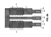
- FIG. 10 is shows a cross-section after the deposition and patterning of a heat spreading layer 55 .
- the heat spreading layer 55 is a good thermal conductor.
- the heat spreading layer 55 is tantalum, deposited by physical vapor deposition, with a thickness of 500-2500 Angstroms.
- the heat spreading layer 55 is a lateral extension of the protection layer 18 that protects the heater from the ink.
- the heat spreading layer 55 is left on throughout the ink chamber and acts as a heat transfer medium from the heater to the ink.
- a chamber and nozzle plate can be fabricated as described in commonly assigned copending patent applications U.S. Ser. Nos. 11/609,375 and 11/609,365, both filed Dec. 12, 2006, the disclosures of which are incorporated by reference herein.
- FIGS. 11 a - 11 c another embodiment is shown.
- FIG. 11 a shows a top plan view of the patterned sacrificial layer 46 in which two holes 56 are formed in the sacrificial layer 46 .
- the processing is then completed as described above with reference to FIGS. 3-10 .
- FIG. 11 b shows a top plan view of a heater of this embodiment.
- FIG. 11 c shows a cross-section taken through line B-B of FIG. 11 b .
- Two support posts 58 in the isolating cavity 36 have been formed in holes 56 .
- the dielectric protective layer 38 When the dielectric protective layer 38 is deposited over the sacrificial layer 46 (as in FIG. 5 ), the dielectric material (e.g. silicon nitride, silicon oxide, or a combination of the two materials) fills the holes 56 .
- the xenon difluoride gas removes the sacrificial layer 46 , the material that is deposited into holes 56 is not removed.
- supports 58 provide mechanical support for heater layer 8 over isolating cavity 36 .
- the diameter of the supports is in the range 0.4-1.0 ⁇ m with a preferred embodiment of 0.6-0.8 ⁇ m diameter. Two supports are shown in FIG. 11 c although the number of supports 58 can vary, for example, between one and ten.
- the number, size, shape and position of the supports 58 is determined by the structural support requirements of the heater stack and is implemented through the mask design for patterning the sacrificial layer 46 .
- the spacing between supports 58 can vary between one third and two thirds of the heater length.
- FIG. 12 a shows a top plan view of the patterned sacrificial layer 46 in which a strip 60 along the heater length is formed in the sacrificial layer.
- FIG. 12 b shows a top plan view of the patterned sacrificial layer 46 in which an opening, for example, a strip 60 , perpendicular to the heater length is formed in the sacrificial layer.
- the fabrication process described herein (starting with dielectric thermal barrier layer 10 including interlayer dielectric layers of CMOS circuitry fabricated on the device) is compatible with the fabrication of drive electronics and logic on the same silicon substrate as the heaters. This is a prerequisite in order to control the large number of heaters needed on a thermal inkjet printhead able to meet current and future requirements for print speed.
- the heater with an underlying cavity that is described in U.S. Pat. No. 5,751,315 uses a polysilicon heater.
- Such a heater material requires high temperature deposition and is not compatible with CMOS fabrication requirements in which the heater is deposited subsequent to the sintering of aluminum for the CMOS circuitry, thereby constraining heater deposition temperature not to exceed 400 C.
- a second prerequisite of thermal inkjet printheads able to meet current and future printing resolution requirements is that heaters for adjacent drop ejectors must be closely spaced, for example at a spacing of 600 to 1200 heaters per inch. For a center to center heater spacing of about 42 microns, corresponding to 600 heaters per inch, the heater width would be approximately 30 microns or less. For a center to center heater spacing of about 21 microns, corresponding to 1200 heaters per inch, the heater width would be approximately 15 microns or less.
- the fabrication processes of the present invention have been demonstrated to be capable of providing heaters having a center to center distance of about 21 microns and having a heater width of less than 15 microns. Fabrication methods described in U.S. Pat. No.
- 5,861,902 for forming a heater having an underlying cavity for thermal isolation have difficulty providing heaters at such close spacing.
- the sacrificial layer (90) is not bounded laterally, as layer 46 is in the present invention (see FIG. 5 ).
- the etching of the sacrificial layer 46 proceeds until it is stopped by the laterally bounding dielectric protective layer 38 which provides a fixed lateral limit to the isolating cavity 36 (see FIGS. 2 and 8 ).
- 5,861,902 may provide adequate manufacturing tolerances for a heater spacing of 300 per inch and a heater width of about 50 microns, it will not provide the tight tolerance on width of the isolating cavity that is required for a heater spacing of 600 or 1200 per inch and a heater width of 30 microns or less.
- the supports 58 are made by providing small holes only through the sacrificial layer 46 and then filling them with the dielectric protective layer 38 .
- dielectric layer 38 is about twice the thickness as sacrificial layer 46 .
- Dielectric layer 38 provides a substantially planar base for electrically resistive heater layer 8 , so that heater layer 8 is nearly planar with substantially uniform thickness, even in embodiments including supports 58 .
- the width of the supports 58 is preferably less than or equal to 1 micron, so that very little heat is transferred through the supports to the substrate.
- the holes are made through two layers (sacrificial silicon dioxide layer 90 and silicon nitride dielectric layer 92).
- the subsequently formed dielectric layer (24) is deliberately kept thin and will not be able to provide a significant amount of planarization.
- resistive heating element (14) of U.S. Pat. No. 5,861,902 is not nearly planar and does not have substantially uniform thickness, as a substantial portion of resistive layer (14) forms the interior of the vertical thermally conductive columns.
- the heater will have an undesirable cool spot.
- the thermally conductive columns may be appropriate in the case of the 50 micron wide heaters contemplated in U.S. Pat. No. 5,861,902 in order to remove heat from interior regions of the heater. However, it has been found for heaters narrower than about 30 microns, such thermally conductive columns are unnecessary. Supports 58 of the present invention are made small in width providing a large thermal impedance, and do not degrade the thermal efficiency of the isolated heater.
- Two sets of devices were fabricated, one set with the isolated heaters of the present invention and one set using non-isolated heaters of the prior art design. Both heaters used the same material and thicknesses for the insulating passivation layer 16 and protective layer 18 . Both heaters were the same size.
- the lower dielectric layer 38 of the isolated heater of the present invention was 0.2 ⁇ m of silicon nitride and the isolating cavity was 0.1 ⁇ m high. Devices were measured in an open pool of ink, without the nozzle plate on. A 0.6 ⁇ sec heat pulse of increasing energy (voltage) was applied until bubble nucleation was observed using a strobed light and a camera for observation.
- the threshold energy for bubble nucleation was ⁇ 70% of the threshold energy required for the non-isolated heater of the prior art design.
- how much of an impact bubble collapse has on lifetime can also be a function of the chamber geometry and whether or not the bubble is vented through the nozzle during drop ejection. Still, the elastic membrane deformation that occurs for the suspended heater of the present invention can have beneficial effects for reducing the amount of cumulative damage to the heater that otherwise could occur due to many firings of the same jet.
- FIGS. 13 a - 13 d schematically illustrates this effect using a simplified schematic cross-section of an isolated heater region 34 of the present invention where the different layers are not delineated.
- FIG. 13 a shows a simplified schematic cross-section of an isolated heater of the present invention at the start of an application of a heat pulse, represented by the current arrows 62 .
- Ink 80 lies above the isolated heater.
- a critical temperature approximately 280 C
- a bubble 70 will start to nucleate.
- the pressure on the heater rapidly rises to approximately 70 Atmospheres and then immediately starts to drop. Modeling has shown that due to this pressure pulse the suspended heater will be pushed down to contact the lower surface 72 as shown schematically in FIG. 13 b.
- the heater returns to its suspended position as shown schematically in FIG. 13 c .
- the pressure inside the bubble has fallen below ambient pressure and the bubble begins contracting.
- the bubble collapses to a point with the inertia from the bubble collapse causing an impact to the heater surface at a point as shown schematically in FIG. 13 d .
- the suspended heater compliantly deforms from the force of the collapsing bubble impact as shown schematically in FIG. 13 d by the directional recoil arrow 66 . It is believed that this recoil minimizes the damage due to bubble collapse that is normally seen on heaters of the prior art.
- Another aspect of the present invention is the heat spreading layer 55 . While the nucleation and expansion of the bubble occurs in ⁇ 1 ⁇ sec, the collapse of the bubble and refilling of the ink occurs on a time scales of the order of 5 ⁇ sec.
- the heat spreading layer 55 will carry heat away from the heater layer over this time scale and allow the ink to preferentially absorb the heat so that it can be ejected during subsequent drop ejections as depicted by heat flow arrows 68 in FIG. 13 d . No boiling of the ink during the ink refilling process was observed during experimental testing.
- Another aspect of the isolated heater region 34 of the present invention is the limited amount of thermal capacitance used in the isolated heater stack 32 .
- the total thickness of the isolated heater stack 32 is limited to ⁇ 0.6 ⁇ m.
- the small amount of energy storing capacity contained in the isolated heater region 34 limits the amount of thermal energy available to the returning ink, thus limiting the temperature rise of the ink, thus improving the thermal efficiency of the heater and decreasing the likelihood of unwanted bubble nucleation during refill.
Landscapes
- Engineering & Computer Science (AREA)
- Manufacturing & Machinery (AREA)
- Particle Formation And Scattering Control In Inkjet Printers (AREA)
Abstract
Description
- 2 Prior art single inkjet ejector
- 4 Silicon substrate
- 6 Prior art heater stack
- 8 Electrically resistive heater layer
- 10 Dielectric thermal barrier layer
- 12 Electrically conductive layer
- 14 Heater area
- 16 Insulating passivation layer
- 18 Protection layer
- 20 Ink chamber
- 22 Nozzle plate
- 24 Nozzle
- 26 Arrows
- 30 Single inkjet ejector of the present invention
- 32 Isolated heater stack of the present invention
- 34 Isolated heater region of the present invention
- 36 Isolating cavity
- 38 Lower dielectric protective layer
- 40 Arrow
- 42 Lateral Arrows
- 44 a,b Metal lead
- 46 Sacrificial layer
- 48 Protrusions
- 50 a,b Vias
- 51 photoresist layer
- 52 openings
- 54 insulating sealing layer
- 55 heat spreading layer
- 56 holes
- 58 supports
- 60 strip along heater
- 62 current arrows
- 64 heat flow arrow
- 66 recoil arrow
- 68 heat flow arrow
- 80 ink
Claims (12)
Priority Applications (4)
| Application Number | Priority Date | Filing Date | Title |
|---|---|---|---|
| US12/143,880 US8540349B2 (en) | 2008-06-23 | 2008-06-23 | Printhead having isolated heater |
| EP09745142A EP2313276B1 (en) | 2008-06-23 | 2009-06-17 | Printhead having isolated heater |
| PCT/US2009/003625 WO2010011250A2 (en) | 2008-06-23 | 2009-06-17 | Printhead having isolated heater |
| JP2011514607A JP5525519B2 (en) | 2008-06-23 | 2009-06-17 | Print head with separated heater |
Applications Claiming Priority (1)
| Application Number | Priority Date | Filing Date | Title |
|---|---|---|---|
| US12/143,880 US8540349B2 (en) | 2008-06-23 | 2008-06-23 | Printhead having isolated heater |
Publications (2)
| Publication Number | Publication Date |
|---|---|
| US20090315951A1 US20090315951A1 (en) | 2009-12-24 |
| US8540349B2 true US8540349B2 (en) | 2013-09-24 |
Family
ID=41430793
Family Applications (1)
| Application Number | Title | Priority Date | Filing Date |
|---|---|---|---|
| US12/143,880 Expired - Fee Related US8540349B2 (en) | 2008-06-23 | 2008-06-23 | Printhead having isolated heater |
Country Status (4)
| Country | Link |
|---|---|
| US (1) | US8540349B2 (en) |
| EP (1) | EP2313276B1 (en) |
| JP (1) | JP5525519B2 (en) |
| WO (1) | WO2010011250A2 (en) |
Families Citing this family (8)
| Publication number | Priority date | Publication date | Assignee | Title |
|---|---|---|---|---|
| US8414786B2 (en) * | 2008-11-05 | 2013-04-09 | Lexmark International, Inc. | Planar heater stack and method for making planar heater stack with cavity within planar heater substrata above substrate |
| US8079672B2 (en) * | 2008-11-05 | 2011-12-20 | Lexmark International, Inc. | Heater stack and method for making heater stack with cavity between heater element and substrate |
| US8172370B2 (en) * | 2008-12-30 | 2012-05-08 | Lexmark International, Inc. | Planar heater stack and method for making planar heater stack |
| US20120091121A1 (en) * | 2010-10-19 | 2012-04-19 | Zachary Justin Reitmeier | Heater stack for inkjet printheads |
| JP6465567B2 (en) * | 2014-05-29 | 2019-02-06 | キヤノン株式会社 | Liquid discharge head |
| US10457048B2 (en) | 2014-10-30 | 2019-10-29 | Hewlett-Packard Development Company, L.P. | Ink jet printhead |
| EP3212414B1 (en) * | 2014-10-30 | 2020-12-16 | Hewlett-Packard Development Company, L.P. | Ink jet printhead |
| EP3322591A4 (en) * | 2015-07-15 | 2019-03-13 | Hewlett-Packard Development Company, L.P. | Adhesion and insulating layer |
Citations (9)
| Publication number | Priority date | Publication date | Assignee | Title |
|---|---|---|---|---|
| JPH07227968A (en) | 1994-02-21 | 1995-08-29 | Canon Inc | Ink jet recording head and production thereof |
| US5751315A (en) | 1996-04-16 | 1998-05-12 | Xerox Corporation | Thermal ink-jet printhead with a thermally isolated heating element in each ejector |
| US5851412A (en) | 1996-03-04 | 1998-12-22 | Xerox Corporation | Thermal ink-jet printhead with a suspended heating element in each ejector |
| US5861902A (en) * | 1996-04-24 | 1999-01-19 | Hewlett-Packard Company | Thermal tailoring for ink jet printheads |
| US6164759A (en) * | 1990-09-21 | 2000-12-26 | Seiko Epson Corporation | Method for producing an electrostatic actuator and an inkjet head using it |
| EP1066966A2 (en) | 1999-06-28 | 2001-01-10 | Sharp Kabushiki Kaisha | Ink-jet head and fabrication method of the same |
| US6273555B1 (en) | 1999-08-16 | 2001-08-14 | Hewlett-Packard Company | High efficiency ink delivery printhead having improved thermal characteristics |
| WO2004048108A1 (en) | 2002-11-23 | 2004-06-10 | Silverbrook Research Pty Ltd | High efficiency thermal ink jet printhead |
| US7128402B2 (en) | 2002-11-23 | 2006-10-31 | Silverbrook Research Pty Ltd | Inkjet printhead with low volume ink displacement |
Family Cites Families (2)
| Publication number | Priority date | Publication date | Assignee | Title |
|---|---|---|---|---|
| JPH0848038A (en) * | 1994-08-08 | 1996-02-20 | Canon Inc | Substrate for liquid jet recording head, production thereof and liquid jet recording apparatus |
| JP2001096749A (en) * | 1999-09-29 | 2001-04-10 | Sharp Corp | Ink-jet head and its manufacturing method |
-
2008
- 2008-06-23 US US12/143,880 patent/US8540349B2/en not_active Expired - Fee Related
-
2009
- 2009-06-17 JP JP2011514607A patent/JP5525519B2/en not_active Expired - Fee Related
- 2009-06-17 WO PCT/US2009/003625 patent/WO2010011250A2/en active Application Filing
- 2009-06-17 EP EP09745142A patent/EP2313276B1/en not_active Not-in-force
Patent Citations (11)
| Publication number | Priority date | Publication date | Assignee | Title |
|---|---|---|---|---|
| US6164759A (en) * | 1990-09-21 | 2000-12-26 | Seiko Epson Corporation | Method for producing an electrostatic actuator and an inkjet head using it |
| JPH07227968A (en) | 1994-02-21 | 1995-08-29 | Canon Inc | Ink jet recording head and production thereof |
| US5851412A (en) | 1996-03-04 | 1998-12-22 | Xerox Corporation | Thermal ink-jet printhead with a suspended heating element in each ejector |
| US5751315A (en) | 1996-04-16 | 1998-05-12 | Xerox Corporation | Thermal ink-jet printhead with a thermally isolated heating element in each ejector |
| US5861902A (en) * | 1996-04-24 | 1999-01-19 | Hewlett-Packard Company | Thermal tailoring for ink jet printheads |
| EP1066966A2 (en) | 1999-06-28 | 2001-01-10 | Sharp Kabushiki Kaisha | Ink-jet head and fabrication method of the same |
| US6340223B1 (en) * | 1999-06-28 | 2002-01-22 | Sharp Kabushiki Kaisha | Ink-jet head and fabrication method of the same |
| US6273555B1 (en) | 1999-08-16 | 2001-08-14 | Hewlett-Packard Company | High efficiency ink delivery printhead having improved thermal characteristics |
| WO2004048108A1 (en) | 2002-11-23 | 2004-06-10 | Silverbrook Research Pty Ltd | High efficiency thermal ink jet printhead |
| US7128402B2 (en) | 2002-11-23 | 2006-10-31 | Silverbrook Research Pty Ltd | Inkjet printhead with low volume ink displacement |
| US7128400B1 (en) | 2002-11-23 | 2006-10-31 | Silverbrook Research Pty Ltd | Very high efficiency thermal ink jet printhead |
Also Published As
| Publication number | Publication date |
|---|---|
| WO2010011250A2 (en) | 2010-01-28 |
| EP2313276A2 (en) | 2011-04-27 |
| EP2313276B1 (en) | 2012-10-03 |
| WO2010011250A3 (en) | 2010-04-15 |
| US20090315951A1 (en) | 2009-12-24 |
| JP5525519B2 (en) | 2014-06-18 |
| JP2011525437A (en) | 2011-09-22 |
Similar Documents
| Publication | Publication Date | Title |
|---|---|---|
| US8540349B2 (en) | Printhead having isolated heater | |
| KR100484168B1 (en) | Ink jet printhead and manufacturing method thereof | |
| JP3388240B2 (en) | INK JET PRINT HEAD AND ITS MANUFACTURING METHOD | |
| US7018017B2 (en) | Monolithic ink-jet printhead having a heater disposed between dual ink chambers and method for manufacturing the same | |
| KR100493160B1 (en) | Monolithic ink jet printhead having taper shaped nozzle and method of manufacturing thereof | |
| JP2002225292A (en) | Method for manufacturing ink jet print head having hemispherical ink chamber | |
| JP2002079679A (en) | Ink jet printing head and method of fabricating the same | |
| US20070046730A1 (en) | Inkjet printhead and method of manufacturing the same | |
| KR100499148B1 (en) | Inkjet printhead | |
| KR100552664B1 (en) | Monolithic ink jet printhead having ink chamber defined by side wall and method of manufacturing thereof | |
| KR100717034B1 (en) | Thermally driven type inkjet printhead | |
| JP2004237732A (en) | Ink jet printhead and method for manufacturing the same | |
| KR100723415B1 (en) | Method of fabricating inkjet printhead | |
| KR100528342B1 (en) | Driving method of inkjet printhead | |
| KR20040035910A (en) | Monolithic ink jet printhead with metal nozzle plate and method of manufacturing thereof | |
| JP2004142462A (en) | Inkjet printhead and its manufacturing method | |
| KR101602996B1 (en) | Thermal inkjet printhead with heating element in recessed substrate cavity | |
| JP2005047270A (en) | Ink jet printing head and its manufacturing method | |
| KR100668293B1 (en) | Bubble-jet type inkjet print head | |
| KR100421027B1 (en) | Inkjet printhead and manufacturing method thereof | |
| KR100499147B1 (en) | Monolithic inkjet printhead having auxiliary heater | |
| KR20060070696A (en) | Thermally driven monolithic inkjet printhead and method of manufacturing the same |
Legal Events
| Date | Code | Title | Description |
|---|---|---|---|
| AS | Assignment |
Owner name: EASTMAN KODAK, NEW YORK Free format text: ASSIGNMENT OF ASSIGNORS INTEREST;ASSIGNOR:LEBENS, JOHN A.;REEL/FRAME:021133/0285 Effective date: 20080619 |
|
| AS | Assignment |
Owner name: EASTMAN KODAK COMPANY, NEW YORK Free format text: CORRECTIVE ASSIGNMENT TO CORRECT THE ONLY FIRST INVENTOR WAS ENTERED ON RECORDATION FORM - APPLICANT ERROR. ASSIGNMENT SHOWS ALL INVENTORS. PREVIOUSLY RECORDED ON REEL 021133 FRAME 0285;ASSIGNORS:LEBENS, JOHN A.;DELAMETTER, CHRISTOPHER N.;TRAUERNICHT, DAVID P.;AND OTHERS;REEL/FRAME:021497/0165 Effective date: 20080619 Owner name: EASTMAN KODAK COMPANY, NEW YORK Free format text: CORRECTIVE ASSIGNMENT TO CORRECT THE ONLY FIRST INVENTOR WAS ENTERED ON RECORDATION FORM - APPLICANT ERROR. ASSIGNMENT SHOWS ALL INVENTORS. PREVIOUSLY RECORDED ON REEL 021133 FRAME 0285. ASSIGNOR(S) HEREBY CONFIRMS THE OMITTED INVENTORS HAVE NOW BEEN ENTERED.;ASSIGNORS:LEBENS, JOHN A.;DELAMETTER, CHRISTOPHER N.;TRAUERNICHT, DAVID P.;AND OTHERS;REEL/FRAME:021497/0165 Effective date: 20080619 |
|
| AS | Assignment |
Owner name: CITICORP NORTH AMERICA, INC., AS AGENT, NEW YORK Free format text: SECURITY INTEREST;ASSIGNORS:EASTMAN KODAK COMPANY;PAKON, INC.;REEL/FRAME:028201/0420 Effective date: 20120215 |
|
| FEPP | Fee payment procedure |
Free format text: PAYER NUMBER DE-ASSIGNED (ORIGINAL EVENT CODE: RMPN); ENTITY STATUS OF PATENT OWNER: LARGE ENTITY Free format text: PAYOR NUMBER ASSIGNED (ORIGINAL EVENT CODE: ASPN); ENTITY STATUS OF PATENT OWNER: LARGE ENTITY |
|
| AS | Assignment |
Owner name: WILMINGTON TRUST, NATIONAL ASSOCIATION, AS AGENT, MINNESOTA Free format text: PATENT SECURITY AGREEMENT;ASSIGNORS:EASTMAN KODAK COMPANY;PAKON, INC.;REEL/FRAME:030122/0235 Effective date: 20130322 Owner name: WILMINGTON TRUST, NATIONAL ASSOCIATION, AS AGENT, Free format text: PATENT SECURITY AGREEMENT;ASSIGNORS:EASTMAN KODAK COMPANY;PAKON, INC.;REEL/FRAME:030122/0235 Effective date: 20130322 |
|
| STCF | Information on status: patent grant |
Free format text: PATENTED CASE |
|
| AS | Assignment |
Owner name: JPMORGAN CHASE BANK, N.A., AS ADMINISTRATIVE, DELAWARE Free format text: INTELLECTUAL PROPERTY SECURITY AGREEMENT (FIRST LIEN);ASSIGNORS:EASTMAN KODAK COMPANY;FAR EAST DEVELOPMENT LTD.;FPC INC.;AND OTHERS;REEL/FRAME:031158/0001 Effective date: 20130903 Owner name: BARCLAYS BANK PLC, AS ADMINISTRATIVE AGENT, NEW YORK Free format text: INTELLECTUAL PROPERTY SECURITY AGREEMENT (SECOND LIEN);ASSIGNORS:EASTMAN KODAK COMPANY;FAR EAST DEVELOPMENT LTD.;FPC INC.;AND OTHERS;REEL/FRAME:031159/0001 Effective date: 20130903 Owner name: PAKON, INC., NEW YORK Free format text: RELEASE OF SECURITY INTEREST IN PATENTS;ASSIGNORS:CITICORP NORTH AMERICA, INC., AS SENIOR DIP AGENT;WILMINGTON TRUST, NATIONAL ASSOCIATION, AS JUNIOR DIP AGENT;REEL/FRAME:031157/0451 Effective date: 20130903 Owner name: BARCLAYS BANK PLC, AS ADMINISTRATIVE AGENT, NEW YO Free format text: INTELLECTUAL PROPERTY SECURITY AGREEMENT (SECOND LIEN);ASSIGNORS:EASTMAN KODAK COMPANY;FAR EAST DEVELOPMENT LTD.;FPC INC.;AND OTHERS;REEL/FRAME:031159/0001 Effective date: 20130903 Owner name: EASTMAN KODAK COMPANY, NEW YORK Free format text: RELEASE OF SECURITY INTEREST IN PATENTS;ASSIGNORS:CITICORP NORTH AMERICA, INC., AS SENIOR DIP AGENT;WILMINGTON TRUST, NATIONAL ASSOCIATION, AS JUNIOR DIP AGENT;REEL/FRAME:031157/0451 Effective date: 20130903 Owner name: JPMORGAN CHASE BANK, N.A., AS ADMINISTRATIVE, DELA Free format text: INTELLECTUAL PROPERTY SECURITY AGREEMENT (FIRST LIEN);ASSIGNORS:EASTMAN KODAK COMPANY;FAR EAST DEVELOPMENT LTD.;FPC INC.;AND OTHERS;REEL/FRAME:031158/0001 Effective date: 20130903 Owner name: BANK OF AMERICA N.A., AS AGENT, MASSACHUSETTS Free format text: INTELLECTUAL PROPERTY SECURITY AGREEMENT (ABL);ASSIGNORS:EASTMAN KODAK COMPANY;FAR EAST DEVELOPMENT LTD.;FPC INC.;AND OTHERS;REEL/FRAME:031162/0117 Effective date: 20130903 |
|
| FPAY | Fee payment |
Year of fee payment: 4 |
|
| AS | Assignment |
Owner name: FAR EAST DEVELOPMENT LTD., NEW YORK Free format text: RELEASE BY SECURED PARTY;ASSIGNOR:JP MORGAN CHASE BANK, N.A., AS ADMINISTRATIVE AGENT;REEL/FRAME:050239/0001 Effective date: 20190617 Owner name: CREO MANUFACTURING AMERICA LLC, NEW YORK Free format text: RELEASE BY SECURED PARTY;ASSIGNOR:JP MORGAN CHASE BANK, N.A., AS ADMINISTRATIVE AGENT;REEL/FRAME:050239/0001 Effective date: 20190617 Owner name: KODAK PORTUGUESA LIMITED, NEW YORK Free format text: RELEASE BY SECURED PARTY;ASSIGNOR:JP MORGAN CHASE BANK, N.A., AS ADMINISTRATIVE AGENT;REEL/FRAME:050239/0001 Effective date: 20190617 Owner name: KODAK AVIATION LEASING LLC, NEW YORK Free format text: RELEASE BY SECURED PARTY;ASSIGNOR:JP MORGAN CHASE BANK, N.A., AS ADMINISTRATIVE AGENT;REEL/FRAME:050239/0001 Effective date: 20190617 Owner name: QUALEX, INC., NEW YORK Free format text: RELEASE BY SECURED PARTY;ASSIGNOR:JP MORGAN CHASE BANK, N.A., AS ADMINISTRATIVE AGENT;REEL/FRAME:050239/0001 Effective date: 20190617 Owner name: NPEC, INC., NEW YORK Free format text: RELEASE BY SECURED PARTY;ASSIGNOR:JP MORGAN CHASE BANK, N.A., AS ADMINISTRATIVE AGENT;REEL/FRAME:050239/0001 Effective date: 20190617 Owner name: FPC, INC., NEW YORK Free format text: RELEASE BY SECURED PARTY;ASSIGNOR:JP MORGAN CHASE BANK, N.A., AS ADMINISTRATIVE AGENT;REEL/FRAME:050239/0001 Effective date: 20190617 Owner name: KODAK REALTY, INC., NEW YORK Free format text: RELEASE BY SECURED PARTY;ASSIGNOR:JP MORGAN CHASE BANK, N.A., AS ADMINISTRATIVE AGENT;REEL/FRAME:050239/0001 Effective date: 20190617 Owner name: KODAK IMAGING NETWORK, INC., NEW YORK Free format text: RELEASE BY SECURED PARTY;ASSIGNOR:JP MORGAN CHASE BANK, N.A., AS ADMINISTRATIVE AGENT;REEL/FRAME:050239/0001 Effective date: 20190617 Owner name: KODAK AMERICAS, LTD., NEW YORK Free format text: RELEASE BY SECURED PARTY;ASSIGNOR:JP MORGAN CHASE BANK, N.A., AS ADMINISTRATIVE AGENT;REEL/FRAME:050239/0001 Effective date: 20190617 Owner name: LASER PACIFIC MEDIA CORPORATION, NEW YORK Free format text: RELEASE BY SECURED PARTY;ASSIGNOR:JP MORGAN CHASE BANK, N.A., AS ADMINISTRATIVE AGENT;REEL/FRAME:050239/0001 Effective date: 20190617 Owner name: PAKON, INC., NEW YORK Free format text: RELEASE BY SECURED PARTY;ASSIGNOR:JP MORGAN CHASE BANK, N.A., AS ADMINISTRATIVE AGENT;REEL/FRAME:050239/0001 Effective date: 20190617 Owner name: EASTMAN KODAK COMPANY, NEW YORK Free format text: RELEASE BY SECURED PARTY;ASSIGNOR:JP MORGAN CHASE BANK, N.A., AS ADMINISTRATIVE AGENT;REEL/FRAME:050239/0001 Effective date: 20190617 Owner name: KODAK PHILIPPINES, LTD., NEW YORK Free format text: RELEASE BY SECURED PARTY;ASSIGNOR:JP MORGAN CHASE BANK, N.A., AS ADMINISTRATIVE AGENT;REEL/FRAME:050239/0001 Effective date: 20190617 Owner name: KODAK (NEAR EAST), INC., NEW YORK Free format text: RELEASE BY SECURED PARTY;ASSIGNOR:JP MORGAN CHASE BANK, N.A., AS ADMINISTRATIVE AGENT;REEL/FRAME:050239/0001 Effective date: 20190617 |
|
| AS | Assignment |
Owner name: KODAK (NEAR EAST), INC., NEW YORK Free format text: RELEASE BY SECURED PARTY;ASSIGNOR:JP MORGAN CHASE BANK, N.A., AS ADMINISTRATIVE AGENT;REEL/FRAME:049901/0001 Effective date: 20190617 Owner name: KODAK REALTY, INC., NEW YORK Free format text: RELEASE BY SECURED PARTY;ASSIGNOR:JP MORGAN CHASE BANK, N.A., AS ADMINISTRATIVE AGENT;REEL/FRAME:049901/0001 Effective date: 20190617 Owner name: PFC, INC., NEW YORK Free format text: RELEASE BY SECURED PARTY;ASSIGNOR:JP MORGAN CHASE BANK, N.A., AS ADMINISTRATIVE AGENT;REEL/FRAME:049901/0001 Effective date: 20190617 Owner name: CREO MANUFACTURING AMERICA LLC, NEW YORK Free format text: RELEASE BY SECURED PARTY;ASSIGNOR:JP MORGAN CHASE BANK, N.A., AS ADMINISTRATIVE AGENT;REEL/FRAME:049901/0001 Effective date: 20190617 Owner name: PAKON, INC., NEW YORK Free format text: RELEASE BY SECURED PARTY;ASSIGNOR:JP MORGAN CHASE BANK, N.A., AS ADMINISTRATIVE AGENT;REEL/FRAME:049901/0001 Effective date: 20190617 Owner name: LASER PACIFIC MEDIA CORPORATION, NEW YORK Free format text: RELEASE BY SECURED PARTY;ASSIGNOR:JP MORGAN CHASE BANK, N.A., AS ADMINISTRATIVE AGENT;REEL/FRAME:049901/0001 Effective date: 20190617 Owner name: KODAK PHILIPPINES, LTD., NEW YORK Free format text: RELEASE BY SECURED PARTY;ASSIGNOR:JP MORGAN CHASE BANK, N.A., AS ADMINISTRATIVE AGENT;REEL/FRAME:049901/0001 Effective date: 20190617 Owner name: KODAK IMAGING NETWORK, INC., NEW YORK Free format text: RELEASE BY SECURED PARTY;ASSIGNOR:JP MORGAN CHASE BANK, N.A., AS ADMINISTRATIVE AGENT;REEL/FRAME:049901/0001 Effective date: 20190617 Owner name: KODAK PORTUGUESA LIMITED, NEW YORK Free format text: RELEASE BY SECURED PARTY;ASSIGNOR:JP MORGAN CHASE BANK, N.A., AS ADMINISTRATIVE AGENT;REEL/FRAME:049901/0001 Effective date: 20190617 Owner name: NPEC, INC., NEW YORK Free format text: RELEASE BY SECURED PARTY;ASSIGNOR:JP MORGAN CHASE BANK, N.A., AS ADMINISTRATIVE AGENT;REEL/FRAME:049901/0001 Effective date: 20190617 Owner name: EASTMAN KODAK COMPANY, NEW YORK Free format text: RELEASE BY SECURED PARTY;ASSIGNOR:JP MORGAN CHASE BANK, N.A., AS ADMINISTRATIVE AGENT;REEL/FRAME:049901/0001 Effective date: 20190617 Owner name: KODAK AMERICAS, LTD., NEW YORK Free format text: RELEASE BY SECURED PARTY;ASSIGNOR:JP MORGAN CHASE BANK, N.A., AS ADMINISTRATIVE AGENT;REEL/FRAME:049901/0001 Effective date: 20190617 Owner name: KODAK AVIATION LEASING LLC, NEW YORK Free format text: RELEASE BY SECURED PARTY;ASSIGNOR:JP MORGAN CHASE BANK, N.A., AS ADMINISTRATIVE AGENT;REEL/FRAME:049901/0001 Effective date: 20190617 Owner name: FAR EAST DEVELOPMENT LTD., NEW YORK Free format text: RELEASE BY SECURED PARTY;ASSIGNOR:JP MORGAN CHASE BANK, N.A., AS ADMINISTRATIVE AGENT;REEL/FRAME:049901/0001 Effective date: 20190617 Owner name: QUALEX, INC., NEW YORK Free format text: RELEASE BY SECURED PARTY;ASSIGNOR:JP MORGAN CHASE BANK, N.A., AS ADMINISTRATIVE AGENT;REEL/FRAME:049901/0001 Effective date: 20190617 |
|
| AS | Assignment |
Owner name: QUALEX INC., NEW YORK Free format text: RELEASE BY SECURED PARTY;ASSIGNOR:BARCLAYS BANK PLC;REEL/FRAME:052773/0001 Effective date: 20170202 Owner name: KODAK (NEAR EAST) INC., NEW YORK Free format text: RELEASE BY SECURED PARTY;ASSIGNOR:BARCLAYS BANK PLC;REEL/FRAME:052773/0001 Effective date: 20170202 Owner name: FAR EAST DEVELOPMENT LTD., NEW YORK Free format text: RELEASE BY SECURED PARTY;ASSIGNOR:BARCLAYS BANK PLC;REEL/FRAME:052773/0001 Effective date: 20170202 Owner name: NPEC INC., NEW YORK Free format text: RELEASE BY SECURED PARTY;ASSIGNOR:BARCLAYS BANK PLC;REEL/FRAME:052773/0001 Effective date: 20170202 Owner name: FPC INC., NEW YORK Free format text: RELEASE BY SECURED PARTY;ASSIGNOR:BARCLAYS BANK PLC;REEL/FRAME:052773/0001 Effective date: 20170202 Owner name: LASER PACIFIC MEDIA CORPORATION, NEW YORK Free format text: RELEASE BY SECURED PARTY;ASSIGNOR:BARCLAYS BANK PLC;REEL/FRAME:052773/0001 Effective date: 20170202 Owner name: KODAK PHILIPPINES LTD., NEW YORK Free format text: RELEASE BY SECURED PARTY;ASSIGNOR:BARCLAYS BANK PLC;REEL/FRAME:052773/0001 Effective date: 20170202 Owner name: EASTMAN KODAK COMPANY, NEW YORK Free format text: RELEASE BY SECURED PARTY;ASSIGNOR:BARCLAYS BANK PLC;REEL/FRAME:052773/0001 Effective date: 20170202 Owner name: KODAK AMERICAS LTD., NEW YORK Free format text: RELEASE BY SECURED PARTY;ASSIGNOR:BARCLAYS BANK PLC;REEL/FRAME:052773/0001 Effective date: 20170202 Owner name: KODAK REALTY INC., NEW YORK Free format text: RELEASE BY SECURED PARTY;ASSIGNOR:BARCLAYS BANK PLC;REEL/FRAME:052773/0001 Effective date: 20170202 |
|
| FEPP | Fee payment procedure |
Free format text: MAINTENANCE FEE REMINDER MAILED (ORIGINAL EVENT CODE: REM.); ENTITY STATUS OF PATENT OWNER: LARGE ENTITY |
|
| LAPS | Lapse for failure to pay maintenance fees |
Free format text: PATENT EXPIRED FOR FAILURE TO PAY MAINTENANCE FEES (ORIGINAL EVENT CODE: EXP.); ENTITY STATUS OF PATENT OWNER: LARGE ENTITY |
|
| STCH | Information on status: patent discontinuation |
Free format text: PATENT EXPIRED DUE TO NONPAYMENT OF MAINTENANCE FEES UNDER 37 CFR 1.362 |
|
| FP | Lapsed due to failure to pay maintenance fee |
Effective date: 20210924 |