US8438461B2 - Power consumption in LDPC decoder for low-power applications - Google Patents
Power consumption in LDPC decoder for low-power applications Download PDFInfo
- Publication number
- US8438461B2 US8438461B2 US12/892,183 US89218310A US8438461B2 US 8438461 B2 US8438461 B2 US 8438461B2 US 89218310 A US89218310 A US 89218310A US 8438461 B2 US8438461 B2 US 8438461B2
- Authority
- US
- United States
- Prior art keywords
- decoder
- value
- ldpc
- condition
- vector
- Prior art date
- Legal status (The legal status is an assumption and is not a legal conclusion. Google has not performed a legal analysis and makes no representation as to the accuracy of the status listed.)
- Active, expires
Links
Images


Classifications
-
- H—ELECTRICITY
- H03—ELECTRONIC CIRCUITRY
- H03M—CODING; DECODING; CODE CONVERSION IN GENERAL
- H03M13/00—Coding, decoding or code conversion, for error detection or error correction; Coding theory basic assumptions; Coding bounds; Error probability evaluation methods; Channel models; Simulation or testing of codes
- H03M13/03—Error detection or forward error correction by redundancy in data representation, i.e. code words containing more digits than the source words
- H03M13/05—Error detection or forward error correction by redundancy in data representation, i.e. code words containing more digits than the source words using block codes, i.e. a predetermined number of check bits joined to a predetermined number of information bits
- H03M13/13—Linear codes
-
- H—ELECTRICITY
- H03—ELECTRONIC CIRCUITRY
- H03M—CODING; DECODING; CODE CONVERSION IN GENERAL
- H03M13/00—Coding, decoding or code conversion, for error detection or error correction; Coding theory basic assumptions; Coding bounds; Error probability evaluation methods; Channel models; Simulation or testing of codes
- H03M13/03—Error detection or forward error correction by redundancy in data representation, i.e. code words containing more digits than the source words
- H03M13/05—Error detection or forward error correction by redundancy in data representation, i.e. code words containing more digits than the source words using block codes, i.e. a predetermined number of check bits joined to a predetermined number of information bits
- H03M13/11—Error detection or forward error correction by redundancy in data representation, i.e. code words containing more digits than the source words using block codes, i.e. a predetermined number of check bits joined to a predetermined number of information bits using multiple parity bits
- H03M13/1102—Codes on graphs and decoding on graphs, e.g. low-density parity check [LDPC] codes
- H03M13/1105—Decoding
- H03M13/1111—Soft-decision decoding, e.g. by means of message passing or belief propagation algorithms
- H03M13/1117—Soft-decision decoding, e.g. by means of message passing or belief propagation algorithms using approximations for check node processing, e.g. an outgoing message is depending on the signs and the minimum over the magnitudes of all incoming messages according to the min-sum rule
- H03M13/112—Soft-decision decoding, e.g. by means of message passing or belief propagation algorithms using approximations for check node processing, e.g. an outgoing message is depending on the signs and the minimum over the magnitudes of all incoming messages according to the min-sum rule with correction functions for the min-sum rule, e.g. using an offset or a scaling factor
-
- H—ELECTRICITY
- H03—ELECTRONIC CIRCUITRY
- H03M—CODING; DECODING; CODE CONVERSION IN GENERAL
- H03M13/00—Coding, decoding or code conversion, for error detection or error correction; Coding theory basic assumptions; Coding bounds; Error probability evaluation methods; Channel models; Simulation or testing of codes
- H03M13/03—Error detection or forward error correction by redundancy in data representation, i.e. code words containing more digits than the source words
- H03M13/05—Error detection or forward error correction by redundancy in data representation, i.e. code words containing more digits than the source words using block codes, i.e. a predetermined number of check bits joined to a predetermined number of information bits
- H03M13/11—Error detection or forward error correction by redundancy in data representation, i.e. code words containing more digits than the source words using block codes, i.e. a predetermined number of check bits joined to a predetermined number of information bits using multiple parity bits
- H03M13/1102—Codes on graphs and decoding on graphs, e.g. low-density parity check [LDPC] codes
- H03M13/1105—Decoding
- H03M13/1128—Judging correct decoding and iterative stopping criteria other than syndrome check and upper limit for decoding iterations
-
- H—ELECTRICITY
- H03—ELECTRONIC CIRCUITRY
- H03M—CODING; DECODING; CODE CONVERSION IN GENERAL
- H03M13/00—Coding, decoding or code conversion, for error detection or error correction; Coding theory basic assumptions; Coding bounds; Error probability evaluation methods; Channel models; Simulation or testing of codes
- H03M13/03—Error detection or forward error correction by redundancy in data representation, i.e. code words containing more digits than the source words
- H03M13/05—Error detection or forward error correction by redundancy in data representation, i.e. code words containing more digits than the source words using block codes, i.e. a predetermined number of check bits joined to a predetermined number of information bits
- H03M13/11—Error detection or forward error correction by redundancy in data representation, i.e. code words containing more digits than the source words using block codes, i.e. a predetermined number of check bits joined to a predetermined number of information bits using multiple parity bits
- H03M13/1102—Codes on graphs and decoding on graphs, e.g. low-density parity check [LDPC] codes
- H03M13/1105—Decoding
- H03M13/1131—Scheduling of bit node or check node processing
- H03M13/114—Shuffled, staggered, layered or turbo decoding schedules
-
- H—ELECTRICITY
- H03—ELECTRONIC CIRCUITRY
- H03M—CODING; DECODING; CODE CONVERSION IN GENERAL
- H03M13/00—Coding, decoding or code conversion, for error detection or error correction; Coding theory basic assumptions; Coding bounds; Error probability evaluation methods; Channel models; Simulation or testing of codes
- H03M13/03—Error detection or forward error correction by redundancy in data representation, i.e. code words containing more digits than the source words
- H03M13/05—Error detection or forward error correction by redundancy in data representation, i.e. code words containing more digits than the source words using block codes, i.e. a predetermined number of check bits joined to a predetermined number of information bits
- H03M13/11—Error detection or forward error correction by redundancy in data representation, i.e. code words containing more digits than the source words using block codes, i.e. a predetermined number of check bits joined to a predetermined number of information bits using multiple parity bits
- H03M13/1102—Codes on graphs and decoding on graphs, e.g. low-density parity check [LDPC] codes
- H03M13/1148—Structural properties of the code parity-check or generator matrix
- H03M13/116—Quasi-cyclic LDPC [QC-LDPC] codes, i.e. the parity-check matrix being composed of permutation or circulant sub-matrices
-
- H—ELECTRICITY
- H03—ELECTRONIC CIRCUITRY
- H03M—CODING; DECODING; CODE CONVERSION IN GENERAL
- H03M13/00—Coding, decoding or code conversion, for error detection or error correction; Coding theory basic assumptions; Coding bounds; Error probability evaluation methods; Channel models; Simulation or testing of codes
- H03M13/37—Decoding methods or techniques, not specific to the particular type of coding provided for in groups H03M13/03 - H03M13/35
- H03M13/3707—Adaptive decoding and hybrid decoding, e.g. decoding methods or techniques providing more than one decoding algorithm for one code
- H03M13/3715—Adaptation to the number of estimated errors or to the channel state
-
- H—ELECTRICITY
- H03—ELECTRONIC CIRCUITRY
- H03M—CODING; DECODING; CODE CONVERSION IN GENERAL
- H03M13/00—Coding, decoding or code conversion, for error detection or error correction; Coding theory basic assumptions; Coding bounds; Error probability evaluation methods; Channel models; Simulation or testing of codes
- H03M13/65—Purpose and implementation aspects
- H03M13/6502—Reduction of hardware complexity or efficient processing
-
- H—ELECTRICITY
- H04—ELECTRIC COMMUNICATION TECHNIQUE
- H04L—TRANSMISSION OF DIGITAL INFORMATION, e.g. TELEGRAPHIC COMMUNICATION
- H04L1/00—Arrangements for detecting or preventing errors in the information received
- H04L1/004—Arrangements for detecting or preventing errors in the information received by using forward error control
- H04L1/0045—Arrangements at the receiver end
- H04L1/0047—Decoding adapted to other signal detection operation
- H04L1/005—Iterative decoding, including iteration between signal detection and decoding operation
- H04L1/0051—Stopping criteria
-
- H—ELECTRICITY
- H04—ELECTRIC COMMUNICATION TECHNIQUE
- H04L—TRANSMISSION OF DIGITAL INFORMATION, e.g. TELEGRAPHIC COMMUNICATION
- H04L1/00—Arrangements for detecting or preventing errors in the information received
- H04L1/004—Arrangements for detecting or preventing errors in the information received by using forward error control
- H04L1/0045—Arrangements at the receiver end
- H04L1/0052—Realisations of complexity reduction techniques, e.g. pipelining or use of look-up tables
- H04L1/0053—Realisations of complexity reduction techniques, e.g. pipelining or use of look-up tables specially adapted for power saving
-
- H—ELECTRICITY
- H04—ELECTRIC COMMUNICATION TECHNIQUE
- H04L—TRANSMISSION OF DIGITAL INFORMATION, e.g. TELEGRAPHIC COMMUNICATION
- H04L1/00—Arrangements for detecting or preventing errors in the information received
- H04L1/004—Arrangements for detecting or preventing errors in the information received by using forward error control
- H04L1/0056—Systems characterized by the type of code used
- H04L1/0057—Block codes
Definitions
- This disclosure relates generally to low power data decoding, and more particularly to low power iterative decoders for data encoded with a low-density parity check (LDPC) encoder.
- LDPC low-density parity check
- LDPC codes may be used for effectively correcting errors in information transmitted in a noisy communications channel.
- the information may be encoded (by a LDPC encoder) prior to transmission and then subsequently decoded (by a LDPC decoder) when received.
- LDPC codes may be defined by one of many different types of parity check matrices.
- the structure of an LDPC code's parity check matrix may be, for example, random, cyclic, or quasi-cyclic.
- a LDPC decoder e.g., a flooding decoder
- Flooding decoding such as a min-sum decoding algorithm.
- Such algorithms may decode a received codeword using an iterative process in which each iteration includes two update steps involving check nodes and variable nodes passing messages to one another.
- LDPC decoder may use a layered approach to decoding (layered decoding) to decode LDPC codes. Both layered and flooding decoding approaches involve messages being updated and stored.
- the term message refers to a numerical value, usually representing a log likelihood ratio (LLR) calculated based on the information (e.g., a vector) received from a communications channel by an LDPC decoder.
- LLR log likelihood ratio
- LDPC codes and decoders that are used to decode LDPC codes may be use in numerous applications and devices. For example, data storage, satellite communications, wireless communications, wire-line communications, and power-line communications are applications that may each require the use of LDPC codes and LDPC decoders. Devices such as digital camera flash memory storage, satellites, mobile phones, and other mobile devices may each require the use of LDPC codes and LDPC decoders.
- LDPC decoders that operate without a low power consumption may disadvantageously consume a large amount of power at a high rate.
- traditional LDPC decoders that have a high rate of power consumption may cause the batteries of a mobile device to be drained at a substantially high rate.
- LDPC decoders that implement low-power techniques to reduce the power consumed in the process of decoding LDPC codes.
- the low-power techniques described herein may reduce power consumption without a substantial decrease in performance of the applications that make use of LDPC codes or the devices that make use of low-power LDPC decoders.
- the condition of a channel (e.g., from which a decoder receives information) and/or a device using the decoder may be monitored (e.g., using monitoring circuitry).
- a metric value may be determined based on the condition of the channel and/or the device (e.g., using monitoring circuitry). For example, the number of errors corrected in past received vectors by a LDPC decoder employing an LDPC decoding process and/or the number of past iterations necessary for decoding may be used to determine the condition of the communications channel.
- the metric value may be compared with at least one threshold (e.g., using monitoring circuitry).
- the comparison may be used to determine whether to enable or disable the low-power syndrome check (and/or normal processing of the vector). Based on the comparison indicating the condition, normal decoder processing of the received vector may be disabled, a syndrome may be pre-computed based on an initial message derived from the received vector, and a determination of the validity of the received vector may be made based on the pre-computed syndrome.
- the pre-computed syndrome may allow the LDPC decoder to quickly determine if the received vector is a valid codeword, e.g. during circumstances in which the condition of the communication channel or the device is good. This check may therefore reduce power consumption.
- the low-power syndrome check may reduce unnecessary power consumption from multiple unnecessary iterations of the decoder, e.g., when there is little noise present in the communications channel and few errors have been corrected by the decoder in past received vectors.
- the condition of a channel (e.g., from which a decoder receives information) and/or a device using the decoder may be monitored (e.g., using monitoring circuitry).
- a metric value may be determined based on the condition of the channel and/or the device (e.g., using monitoring circuitry).
- the metric value may be compared with at least one threshold (e.g., using monitoring circuitry). The comparison may be used to determine the appropriate values for the precision and/or scale factor of messages processed by the decoder.
- the bit precision and/or scale factor may be set according to this determined value.
- the bit precision of the decoder may be reduced when there is little noise present in the communications channel and few errors have been corrected by the decoder in past received vectors (i.e., when the condition of the communications channel is good).
- a reduction in the precision of the messages and/or an increase in the scaling factor used for the messages may advantageously reduce power consumption in the decoder (e.g., a LDPC decoder) due to the reduction in the complexity of computations necessary in the decoder during processing.
- an LDPC decoder is described with relation to FIGS. 1-9 , below, this element may be replaced by any type of decoder (e.g., a Turbo Code decoder, a layered decoder, or a flooding decoder).
- the decoder may make use of either hard information (e.g., using a hard decoder such as a bit-flipping decoder) or soft information (e.g., using an iterative soft decoder) to decode incoming information. While certain components of the present disclosure have been described as implemented in hardware and others in software, other configurations may be possible.
- FIG. 1 shows an illustrative block diagram of an error-correcting communication/storage system in accordance with some embodiments
- FIG. 2 shows an illustrative example of the properties of a codeword in accordance with some embodiments
- FIG. 3 shows an illustrative example of a quasi-cyclic parity check matrix in a mother matrix representation in accordance with some embodiments
- FIG. 4 shows a graphical illustration of a parity check matrix and the iterative message passing algorithm implemented in a flooding decoder in accordance with some embodiments
- FIG. 5 shows a simplified block diagram of a layered LDPC decoder with low-power circuitry in accordance with some embodiments
- FIG. 6 shows a message memory block that may be used for changing the precision of messages to reduce power-consumption in accordance with some embodiments
- FIG. 7 shows monitoring logic circuitry that may be used for monitoring decoder statistics in accordance with some embodiments
- FIG. 8 shows a flowchart of a process for a low-power syndrome check used with LDPC decoders in accordance with some embodiments.
- FIG. 9 shows a flowchart of a process for a changing the precision or scale of messages to reduce power consumption in an LDPC decoder in accordance with some embodiments.
- Encoding may generally refer to the process of generating data in a manner that facilitates subsequent detection and/or correction of errors in the data, while decoding may generally refer to the counterpart process of detecting and/or correcting the errors.
- the elements of a coding system that perform encoding and decoding are likewise referred to as encoders and decoders, respectively.
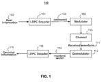
- FIG. 1 shows an illustrative communication or data storage system 100 that utilizes error-correction codes for achieving reliable communication or storage in accordance with some embodiments.
- User information 102 is encoded through encoder 104 .
- User information 102 often referred to as the message information or a message vector, may be grouped into units of k symbols, where each symbol may be binary, ternary, quaternary, or any other suitable type of data. However, for simplicity, embodiments of the present disclosure will be described in terms of binary bits.
- different codes may be used by encoder 104 to achieve different results.
- encoder 104 may encode user information 102 using a low density parity check (LDPC) code.
- the result of encoding user information 102 is codeword 106 , also denoted as c.
- Codeword 106 may be of a predetermined length that may be referred to as n, where n ⁇ k.
- codeword 106 is passed to a modulator 108 .
- Modulator 108 prepares codeword 106 for transmission on channel 110 .
- Modulator 108 may use phase-shift keying, frequency-shift keying, quadrature amplitude modulation, or any suitable modulation technique to modulate codeword 106 into one or more information-carrying signals.
- Channel 110 represents media through which the information-carrying signals travel.
- channel 110 may represent a wired or wireless medium in a communication system, or an electrical (e.g., RAM, ROM), magnetic (e.g., a hard disk), or optical (e.g., CD, DVD or holographic) storage medium in which the information-carrying signals may be stored.
- channel 110 may corrupt the waveform transmitted by modulator 108 .
- the waveform received by demodulator 112 received waveform 111
- Received waveform 111 may be demodulated with demodulator 112 .
- Demodulator 112 may demodulate received waveform 111 with filters, multiplication by periodic functions, or any suitable demodulation technique corresponding to the type of modulation used in modulator 108 .
- the result of demodulation is received vector 114 and this result may contain errors due to channel corruption.
- Received vector 114 may then be processed by LDPC decoder 116 .
- LDPC decoder 116 may be located inside of any device.
- LDPC decoder 116 may be located inside of a flash memory storage, a mobile device, a phone, or a satellite.
- LDPC decoder 116 may have low-power circuitry and monitoring circuitry to facilitate a substantial reduction in power-consumption in the LDPC decoder.
- LDPC decoder 116 is used to correct or detect errors in received vector 114 .
- LDPC decoder 116 uses an iterative message-passing algorithm (e.g. flooding decoding or layered decoding) to correct or detect errors in received vector 114 .
- LDPC decoder 116 calculates or receives an initial log-likelihood-ratio (LLR) message that represents a bit reliability metric for the bits of received vector 114 .
- LLR log-likelihood-ratio
- LDPC decoder 116 computes a LLR message using the equation
- a LLR for each bit that is greater than zero may indicate that a bit value of zero is more likely, while a LLR that is less than zero may indicate that a one bit value of one is more likely.
- LDPC decoder 116 may use the computed LLR messages in the message passing algorithm. When utilizing such an iterative algorithm, LDPC decoder 116 may perform several iterations of the algorithm until the output of LDPC decoder 116 converges to a valid codeword.
- the output of LDPC decoder 116 may fail to converge to a valid codeword. Decoder failure may be caused by a variety of reasons. Because the output of LDPC decoder 116 may never converge to a valid codeword in certain situations, LDPC decoder 116 may be equipped with a maximum iteration limit that is any suitable predetermined number. When LDPC decoder 116 reaches the maximum iteration limit, (i.e., a positive integer, maxIterNum), LDPC decoder 116 may automatically terminate operation and do some post-processing of the received vector or move on to the next received vector 114 . However, if the output of LDPC decoder 116 successfully converges to a valid codeword, LDPC decoder 116 may then output decoded information 118 .
- the maximum iteration limit i.e., a positive integer, maxIterNum
- FIG. 2 shows an illustrative example of the properties of codeword 106 of FIG. 1 in accordance with some embodiments.
- the LDPC codes processed by encoder 104 of FIG. 1 and LDPC decoder 116 of FIG. 1 are conventionally represented by mathematical vector models.
- an LDPC code is described by its parity check matrix H.
- Equation 210 illustrates parity check matrix 212 .
- Parity check matrix 212 is of size [r ⁇ n], corresponding to codewords of length n and syndromes of length r.
- Codewords may be, for example, n-length codeword 106 or n-length received vector 114 of FIG. 1 .
- Syndrome length r satisfies the inequality r ⁇ n ⁇ k and where k is the length of the information being encoded (e.g., length of user information 102 of FIG. 1 ).
- Each bit of codeword 114 corresponds to a column of parity check matrix 212 .
- parity check matrix 212 is multiplied by codeword 214 , the result is syndrome 216 .
- Syndrome 216 is a zero-vector of size [r ⁇ 1] where all elements equal zero.
- codeword 214 is determined to be a valid codeword.
- codeword 214 is determined to be an invalid codeword.
- Parity check matrix 212 has a column weight (“cw”) defined to be the maximum of the set of the number of nonzero entries in each column of parity check matrix 212 .
- Parity check matrix 212 is not unique, and may be chosen, for example, to be computationally convenient and/or to decrease the number of errors generated by the message passing algorithm in LDPC decoder 116 .
- codeword 214 may be decoded in LDPC decoder 116 to produce decoded information 118 .
- quasi-cyclic LDPC code matrices are often used as such codes are very suitable for hardware implementations.
- FIG. 3 shows an illustrative example of quasi-cyclic parity check matrix 310 in a mother matrix representation in accordance with some embodiments.
- a mother matrix representation is a compact way for describing a matrix that may contain a large number of elements.
- the mother matrix representation is equivalent to the normal matrix representation, but may be advantageous in illustrating the structure of a possibly large matrix without the necessity of explicitly listing each element in the matrix.
- a quasi-cyclic code representation is defined by the characteristic that the parity check matrix for that particular code is quasi-cyclic.
- a quasi-cyclic parity check matrix in a mother matrix representation is made up of circular submatrices known as circulants.
- Circulant 340 is one such matrix.
- Circulant 340 is a square matrix—i.e. circulant 340 has the same number of rows as columns. This number is commonly referred to as the circulant size S c .
- circulants have the property that for any given positive integer C i,j ⁇ S c , any row/column of the circulant matrix may be cyclically shifted by C i,j positions to obtain another row/column. For example, the number zero represents identity matrix 330 of size S c .
- the number three represents matrix 340 that is equal to identity matrix 330 with each row cyclically shifted to the right by three positions.
- minus-one denotes the all-zero matrix 320 .
- the phrase “non-zero circulant” will be used to refer any circulant matrix that is not the all-zero matrix.
- parity check matrix 310 is of size [r ⁇ n].
- FIG. 4 shows graphical illustration 400 of a parity check matrix and the iterative message passing algorithm implemented in a flooding decoder in accordance with some embodiments.
- An LDPC code may be graphically represented by a Tanner graph, a bipartite graph showing the relationship between a LDPC code's codeword bits and parity check equations.
- the advantages of using a Tanner graph of a LDPC code may include access to efficient graph-based message-passing algorithms for decoding.
- Variable nodes 401 represent each position in codeword 106 and are denoted by circles. Thus, there may be n variable nodes.
- Variable nodes may also be referred to as symbol or bit nodes.
- Check nodes 405 may represent each syndrome (parity check equation) of LDPC code. For example, there may be n ⁇ k check nodes. Check nodes are denoted by squares.
- Tanner graphs 403 and 404 correspond to parity check matrix 402 .
- the check nodes and variable nodes of Tanner graphs 403 and 404 correspond to the rows and columns of parity check matrix 402 , respectively.
- the undirected edges connecting check nodes with variable nodes correspond to the locations of the non-zero entries of parity check matrix 402 .
- parity check matrix 402 is the adjacency matrix of Tanner graphs 403 and 404 .
- the 1 at the (1,1) location and the 0 at the (1,2) location of parity check matrix 402 may indicate that there is an edge between check node S 1 and variable node V 1 , and that there is no edge between check node S 1 and variable node V 2 , respectively.
- variable node corresponding to that column has a degree of d v .
- d c edges emanating from the check node corresponding to that row. Equivalently, the check node corresponding to that row has a degree of d c .
- the check nodes (e.g. check nodes 405 ) of a Tanner graph may either be satisfied or unsatisfied, where a satisfied node has a binary value of 0 and an unsatisfied node has a binary value of 1.
- the value of each check node may be equal to the sum modulo two of the values of the variable nodes to which it is connected.
- a check node is satisfied (i.e., equal to 0), if the values of the variable nodes connected to the check node sum to an even number and otherwise it is unsatisfied.
- check node S 2 of Tanner graphs 403 and 404 may be satisfied if the values of variable nodes V 2 , V 5 , and V 8 sum to an even number.
- the value of the check nodes may provide a parity check on each codeword received by a LDPC decoder (i.e., LDPC decoder 116 of FIG. 1 ), thereby providing error correction capability to communication/storage system 100 of FIG. 1 .
- Tanner graphs 403 and 404 may be used to illustrate an iterative two-step decoding algorithm known as message passing algorithm 406 .
- Message passing algorithm 406 may be employed by, LDPC decoder 116 of FIG. 1 or any variant of this decoder (e.g., a flooding decoder, or a layered decoder).
- the message passing algorithm performs several rounds (or iterations) 412 of message updates in accordance with the structure of the Tanner graph associated with the parity check matrix of the LDPC codes to be decoded.
- Iteration 412 may be repeated until either the codeword has been decoded or until a threshold number of iterations has been reached.
- the messages that are sent during each step of each iteration of message passing algorithm 406 may depend on the update rules and the scheduling of the update steps.
- each of the variable nodes 401 of FIG. 4 receive an initial LLR message based on information derived from received vector 114 in FIG. 1 .
- a low-power syndrome check may be performed, in some cases, prior to or during the first iteration of message passing algorithm 406 .
- Each iteration of message passing algorithm 406 may include two steps. In the first step, check nodes may update and in the second step variable nodes may update. This process may be repeated until either the codeword has been decoded or until a threshold number of iterations (e.g., maxIterNum) has been reached.
- a threshold number of iterations e.g., maxIterNum
- a group of variable nodes within the set of variable nodes 401 send their current messages to a group of check nodes (e.g. to be processed in the first layer of message passing decoding) within the set of check nodes 405 to which they are connected.
- the group of check nodes then perform update 408 by carrying out computations based on the messages that they receive and a set of update rules.
- These check nodes receive, e.g., d c messages each from a different variable node to which it is connected.
- Each message sent from the group of variable nodes to the group of check nodes may be labeled as a Q type message.
- Each a-posteriori probability (APP) message computed for the group of variable nodes may be labeled as P type message.
- Q type or P type messages may be stored in the LDPC-decoder's memory.
- these messages can be labeled Q 1 through Q d c .
- the group of check nodes may then update by computing a R type message using each Q type message it received and a min approximation. Specifically, using all of the Q type messages it received, each of the check nodes in the group of check nodes may compute a R type message based on the equations
- ScaleR represents a scale factor (which may be set to 1 or any other value) that multiplies the R type message to improve the performance of the LDPC decoder applying this min-sum technique.
- the scale factor may allow the performance of the decoder to approach that of one applying a sum-product technique (that does not use a min approximation).
- the Q k messages i.e. a number k of Q type messages
- the Q k messages may be reconstructed from the P k messages (i.e. a number k of P type messages) and the previous R type messages that may be read from the memory of the LDPC decoder. These newly computed R messages are sent to each of the variable nodes to which the check node is connected.
- a group of check nodes within the set of check nodes 405 sends their current message to a group of variable nodes within the set of variable nodes 401 to which they are connected.
- the group of variable nodes then performs update 410 by carrying out computations based on the messages that they receive and a set of update rules.
- These variable nodes receive, e.g., d v messages each from different check nodes to which it is connected.
- Each message sent from the group of check nodes to the group of variable nodes may be labeled as a R type message.
- the messages sent from check nodes to a variable node can be labeled R 1 through R d v .
- the group of variable nodes may then update by computing a Q type message using each R type message it received. Specifically, using the initially received LLR message, and each of the R type messages received, each variable node of the group of variable nodes may compute a Q type message based on the equation
- ScaleQ may represent a scale factor (that may be set to 1 or any other value) that multiplies the Q type message to improve the performance of the LDPC decoder.
- both R and Q type messages may be “scaled” by the multiplication of each by ScaleR and ScaleQ, respectively.
- message update steps may be performed to compute a P type message (also known as an a-posteriori probability (APP) message).
- APP a-posteriori probability
- each variable node of the group of variable nodes may also compute an extrinsic (LLR EXT ) message based on the equations:
- FIG. 5 shows a simplified block diagram of layered LDPC decoder 500 (e.g., a layered variant of LDPC decoder 116 of FIG. 1 ) with low-power circuitry in accordance with some embodiments.
- LDPC decoder 500 includes Q memory 510 , R memory 516 , syndrome computation unit 517 , processing/update block 519 , multiplexer 511 and additional components used to decode a received vector (e.g. received vector 114 of FIG. 1 ), and memory to store other types of messages or information (e.g., hard decisions).
- Multiplexer 511 includes Switch-To-Power-Save (STPS) select input 513 (equivalently, STPS switch) as well as inputs 515 and 520 .
- STPS Switch-To-Power-Save
- Low-power circuitry in layered LDPC decoder 500 or any other decoder may include any of these components.
- the low-power circuitry may include multiplexer 511 , syndrome computation unit 5
- Q-memory 510 and R-memory 516 store variable-to-check (bit-to-check) messages (Q-type messages) and check-to-variable (check-to-bit) messages (R type messages), respectively.
- R memory 516 may store data used for compact storage of R type messages (e.g. Min1, Min2, Min1Index, Min2Index, AccumulatedSign). This memory can be used to derive R-type messages.
- multiplexer 511 allows for a choice between performing a low-power syndrome check in the first iteration or part of the first iteration or normal decoding without a low-power syndrome check.
- the low-power syndrome check may allow the LDPC decoder to quickly determine if the received vector is a valid codeword when, e.g., the condition of the communication channel (e.g., channel 110 of FIG. 1 ) is good. A power-savings can therefore be realized by the decoder from not having to process the received vector any further.
- the signal-to-noise ratio (SNR) of the communications channel is high, then the condition of the communications channel is good, and the low-power syndrome check may be enabled. A power saving may be realized as a result of the low-power syndrome check being enabled. If however, the SNR of the communications channel is low, then the condition of the communications channel is bad, and the low-power syndrome check may be disabled.
- the signal to noise ratio may be determined by, for example, using monitoring logic circuitry as described below, and/or by any channel monitoring circuitry internal or external to decoder 500 .
- Multiplexer 511 includes STPS select input 513 as well as inputs 515 and 520 .
- STPS select input 513 allows multiplexer 511 to choose either input 515 or input 520 to be output to syndrome computation unit 517 .
- STPS select input 513 of multiplexer 511 is equal to one, then the low-power syndrome check is enabled. Multiplexer 511 then chooses input 515 (the sign of the initial LLR message received or computed by the decoder) to be output to syndrome computation unit 517 .
- STPS select input 513 (equivalently STPS switch 513 ) may be used to substantially stop normal decoder processing, e.g., when the input is set to one and when the low-power syndrome check is enabled.
- normal LDPC decoder processing e.g., reading and writing to R memory 516 , reading and writing to Q memory 510 , etc.
- multiplexer 511 If STPS select input 513 of multiplexer 511 is equal to zero, then the low-power syndrome check is disabled. Multiplexer 511 then chooses input 520 (a hard decoded (HD) data from the LDPC decoder, which is equal to the sign of the APP (P type) message in LDPC decoder) to be output to syndrome computation unit 517 .
- HD hard decoded
- APP P type
- LDPC decoder processing of the received vector is performed. Normal decoder processing, as described below, may also be performed if the low-power syndrome check does not determine that the received vector is a valid codeword.
- LDPC decoder 500 may operate using a decoding approach as described in FIG. 4 .
- an initial LLR message based on information from the received vector (e.g., received vector 114 of FIG. 1 ) is computed or received by the LDPC decoder (e.g., layered LDPC decoder 500 ).
- the variable node (equivalently, bit node) messages in decoder (Q-type messages) may be equal to the initial LLR messages computed or received.
- Processing/update block 519 may read R type messages from R memory 516 and/or Q type messages from Q memory 510 and may process and update these messages (e.g., using the equations described above). Processing/update block 519 may store the updated R type messages to R memory 516 and/or the update Q type messages to Q memory 510 . Processing/update block 519 may also output updated HD data to the input 520 of multiplexer 511 .
- the syndrome computation unit 517 computes a syndrome (e.g., similar to syndrome 216 of FIG. 2 ) based on the messages it receives at its input and the parity check matrix associated with the LDPC code being applied. Syndrome computation unit 517 may pass the computed syndrome to a convergence logic (not shown) and/or to a hard decision memory (also not shown). The convergence logic may determine that the received vector is valid based on the syndromes it receives. For example, if the syndromes calculated are all zero, then the convergence logic may determine that the received vector is a valid codeword and may terminate any further processing of the receive vector by LDPC decoder 500 .
- a syndrome e.g., similar to syndrome 216 of FIG. 2
- Syndrome computation unit 517 may pass the computed syndrome to a convergence logic (not shown) and/or to a hard decision memory (also not shown).
- the convergence logic may determine that the received vector is valid based on the syndromes it receives. For example, if the syndromes calculated are all zero, then the convergence
- the convergence logic may determine that the received vector is an invalid codeword and may allow further processing of the received vector by LDPC decoder 500 (i.e., additional iterations). The iterations may continue until the LDPC decoder converges to a valid codeword or until the maximum iteration limit (i.e., a positive integer, maxIterNum) is reached, whichever comes first.
- the maximum iteration limit i.e., a positive integer, maxIterNum
- STPS select input 513 of multiplexer 511 is equal to one.
- an initial LLR message based on information from the received vector (e.g., received vector 114 of FIG. 1 ) is computed or received by the LDPC decoder (e.g., layered LDPC decoder 500 ). The sign of each value in the initial LLR message may be computed.
- the sign may be equal to zero if the i th value in the initial LLR message indicates that the probability of i th bit in the received vector being “0” is greater than or equal to the probability of it being “1.”
- the sign may be equal to one if the i th value in the initial LLR message indicates that the probability of i th bit in the received vector being “1” is greater than the probability of it being “0.”
- Input 515 to multiplexer 511 is the sign of each value in the initial LLR message. Since STPS select input 513 is equal to one, the sign of each value in the initial LLR message is chosen by multiplexer 511 to be output to syndrome computation unit 517 . Any other processing of the received vector (e.g., reading/writing R memory 516 and reading/writing Q memory 510 etc) may not be performed.
- Syndrome computation unit 517 computes syndromes based on the sign of each value in the initial LLR message that it receives at its input and the parity check matrix (e.g., parity check matrix 212 of FIG. 2 ) associated with the LDPC code being applied. Syndrome computation unit 517 may pass the computed syndromes to a convergence logic (not shown) and/or to a hard decision memory (also not shown). The convergence logic may determine that the received vector is valid based on the syndromes it receives. For example, if the syndromes calculated are all zero, then the convergence logic may determine that the received vector is a valid codeword and may terminate any further processing of the receive vector by LDPC decoder 500 .
- the convergence logic may determine that the received vector is an invalid codeword and may allow further processing (normal decoder processing, described above) of the received vector by layered LDPC decoder 500 .
- the convergence logic may determine that the received vector is invalid after processing any layer associated with a non-zero syndrome. The low-power syndrome check may then be stopped and LDPC decoder 500 may continue with normal decoder processing, described above.
- the condition of the communications channel (e.g., channel 110 of FIG. 1 ) and/or the device using the LDPC decoder may be monitored (e.g., by monitoring logic circuitry, discussed below).
- the monitoring may determine whether to enable or disable the low-power syndrome check (i.e., to set STPS select input 513 to be one or zero, respectively). For example, when the signal-to-noise ratio (SNR) associated with the communications channel is high, indicating that the channel condition is good, STPS select input 513 is set to one, which enables the low-power syndrome check. When the SNR associated with the communications channel is low, indicating that the channel condition is bad, STPS select input 513 is set to zero, which disables the low-power syndrome check.
- SNR signal-to-noise ratio
- the determination of whether the SNR value is high or low may be made based on thresholds, based on a range of values, or using other techniques.
- a high SNR value may be one that is in the range of SNR values above or within the waterfall or the error floor region of a LDPC code's performance curve.
- a low SNR value may be one that is in the range of SNR values within or below the waterfall region of the LDPC code's performance curve.
- a SNR value greater than a first threshold e.g., set at, for example, any value above, 0.05 dB
- a first threshold e.g., set at, for example, any value above, 0.05 dB
- a SNR value less than a second threshold may be a low SNR value.
- the determination of whether the SNR value is high or low and/or the condition of the communications channel may be based on the past number of iterations taken to decode a codeword and/or the number of errors corrected by the decoder while decoding a codeword, and one or more thresholds.
- the low-power syndrome check When the low-power syndrome check is enabled, the check will take at most one extra LDPC decoder iteration.
- the low-power syndrome check may only take a part (fraction) of an iteration because the check may be stopped when the first layer associated with a non-zero syndrome is found. This may typically occur early in during the check. For example, the check may be stopped after only one or two layers when the channel SNR is low. As another example, if the channel SNR is high, the check may be stopped after approximately one-third of an iteration or one-fourth of an iteration, if the LDPC parity check matrix has column weight, cw, equal to 3 or 4, respectively.
- the low-power syndrome check when the low-power syndrome check is enabled, either one iteration of the decoder will be spent to determine that the received vector is a valid codeword or a fraction of an iteration will be spent to determine that this vector is not a valid codeword and further processing will be required. During good channel conditions, the low-power syndrome check will therefore substantially reduce power-consumption in the decoder by limiting unnecessary decoder processing.
- this element may be replaced by any type of decoder (e.g., the LDPC decoder could instead or more particularly be any type of layered decoder, any type of flooding decoder, or any other type of decoder).
- the decoder may also be any variant of these decoders (e.g., a hard decoder, a bit-flipping decoder, a soft decoder, or any other variant of a decoder). Additionally, the decoder may make use of either hard information or soft information to decode received vectors.
- FIG. 6 shows message memory block 600 that may be used for changing the bit precision of messages to reduce power-consumption in accordance with some embodiments.
- Message memory block 600 may store each R and/or Q type message using a fixed number of bits, of which some bits are active and some are not active.
- Message memory block 600 may include any number of active bits.
- message memory block 600 may include active bits 602 , 606 , 608 , or 610 .
- Message memory block 600 may include masked bits 603 , 605 , 607 , or 609 .
- Message memory block 600 may also include memory access line 620 .
- Message memory block 600 may represent a portion of Q memory (e.g., Q memory 510 of FIG.
- Message memory block 600 may include active bits 602 , 606 , 608 , or 610 that each represent a desired bit precision (“BP”) for R and/or Q type messages in the LDPC decoder.
- BP may be equal to M, a positive integer value.
- BP may have a maximum desired precision equal to L, a positive integer value.
- M may be equal to three and L may be equal to eight.
- M may be equal to one and L may be equal to six.
- Active bits are the bits that are used to represent, read, and write the R and/or Q type messages stored respectively in the R and/or Q memories.
- the number of active bits represent the bit precision, BP, of the R and/or Q type messages.
- the bits that are not active may be masked or powered down so that they are not used, not read, and/or not written.
- message memory block 600 may have M active bits 602 and L ⁇ M masked bits 603 .
- Message memory block 600 may have M+1 active bits 604 and L ⁇ (M+1) masked bits 605 .
- Message memory block 600 may have M+2 active bits 606 and L ⁇ (M+2) masked bits 607 .
- Message memory block 600 may have L ⁇ 1 active bits 608 and one masked bit 609 .
- Message memory block 600 may have L active bits 610 .
- the number of active bits may be controlled by a register, ACTIVE_BITS. This register may be implemented inside or outside of message memory block 600 and controlled by, for example, monitoring logic circuitry, as discussed below.
- the condition of the communications channel (e.g., channel 110 of FIG. 1 ) and/or the device using the LDPC decoder may be monitored (e.g., by monitoring logic circuitry, discussed below).
- the monitoring may determine the bit precision, BP, of R and/or Q type messages. For example, when the signal-to-noise ratio (SNR) associated with the communications channel is high, as described above, indicating that the channel condition is good, the bit precision of the R and/or Q type messages (e.g., controlled by the ACTIVE_BITS register) may be set at a low number.
- SNR signal-to-noise ratio
- the precision of the R and/or Q type messages may be set at a high number.
- the control of STPS select input 513 of multiplexer 511 by monitoring logic circuitry will be discussed in greater detail, below, with reference to FIG. 7 .
- Memory access line 620 may be used to read and write R and/or Q messages to and from message memory block 600 . In some embodiments, memory access line 620 may be used to read or write only the active bits associated with each of these R and/or Q messages.
- R and/or Q type messages When the condition of the communications channel is good, setting the precision of R and/or Q type messages to a lower number will substantially reduce power-consumption in the LDPC decoder.
- a reduced precision for R and/or Q type messages may reduce the amount of processing that is necessary in the LDPC decoder, thereby substantially reducing decoder power consumption.
- FIG. 7 shows monitoring logic circuitry 700 that may be used for monitoring decoder statistics in accordance with some embodiments.
- Control logic circuitry 700 includes memory 704 , newest metric value 706 , oldest metric value 708 , control logic unit 712 , and output signal 714 .
- Control logic circuitry 700 may also include adder 702 .
- newest metric value 706 and oldest metric value 708 may be, for example, statistics or numbers related to the condition of the communications channel or the condition of the device.
- Control logic circuitry 700 may be located inside or outside of a LDPC decoder (e.g., layered LDPC decoder 500 of FIG. 5 ).
- Memory 704 stores a window of W numbers.
- memory 704 may be used to store the monitored number of bit errors corrected by an LDPC decoder in the past. This may be a first metric.
- the number of bits corrected by the decoder (“input errors”) in received vectors may be determined by comparing each of the past W received vectors to each corresponding output codewords from the LDPC decoder (when the decoder converged) and may be stored in memory 704 .
- a large number of past errors could indicate that the condition of the communications channel (e.g., channel 110 of FIG. 1 ) is bad (e.g., is associated with a low SNR).
- a small number of past errors could indicate that the condition of the communications channel (e.g., channel 110 of FIG. 1 ) is good (e.g., is associated with a high SNR).
- a determination that the number of past errors is small may be made based on a comparison of the number with a threshold (discussed below) or based on the number of received vectors that require, e.g., less than 1.5 or 2 iterations of the decoder, per circulant.
- the number of past errors being small may be determined by the code rate of the LDPC code.
- a determination that the number of past errors is large may be made based on a comparison of the number with a threshold (discussed below) or based on the number of received vectors that require, e.g., more than 1.5 or 2 iterations of the decoder, per circulant.
- memory 704 may be used to store the monitored past W numbers of iterations the LDPC decoder needed to converge for the past W codewords (equivalently the past W blocks or sectors). This may be a second metric. Using the second metric, if the maximum number of possible iterations for the decoder is denoted maxIterNum, each number stored in memory 704 may be at most log 2 (maxIterNum) bits long. A large number of past iterations indicates that the condition of the communications channel is bad (e.g., is associated with a low SNR). A small number of past iterations indicates that the condition of the communications channel is good (e.g., is associated with a high SNR).
- memory 704 may be used to store W/S numbers. Each number may correspond to iterations of the LDPC decoder needed to converge for the past S codewords (equivalently blocks or sectors). Using this approach, each number stored may be at most log 2 (S ⁇ maxIterNum) bits long and the size of memory necessary to store history information may be reduced.
- S is set to a value that is less than or equal to W and both the values of S and W may be design choices. For example, if the values of S and W are both small, monitoring logic circuitry 700 may be very sensitive to changes in SNR. If the values of S is large and the value of W is set equal to the value of S, monitoring logic circuitry 700 may be less sensitive to changes in SNR. This assumes that correlation between blocks (or sectors) exists over the larger window, W.
- any metric related to the condition of the communications channel or the condition of the device, in which the decoder is implemented may be monitored by monitoring circuitry.
- the condition of the device in which the decoder is implemented may be correlated with measurements including the number of times the device is used in various intervals of time, the number of times it performed an operation in various intervals of time, and/or the amount of processing it performed in various intervals of time. At least one of these measurements may be compared to one or more thresholds, each set at an appropriate value for the device in which the decoder is implemented. For example in the case when one threshold is used, if the measurement is above the threshold, then the condition of the device in which the decoder is implemented may be determined to be bad.
- the condition of the device in which the decoder is implemented may be determined to be good. For example, on a flash memory device implementing a decoder, the number of times that a read operation is performed may be monitored and the condition of the flash memory device may be determined from this number.
- Memory 704 may be used to store statistics or numbers related to the metric. These statistics or numbers are used to determine whether to enable or disable the low-power syndrome check, change the bit precision of R and/or Q type messages, and/or change the scale of R and/or Q type messages.
- a low number of uses of the device, a low number of times that it performed an operation, and/or a low amount of processing may indicate that the condition of the device, in which the decoder is implemented, is good.
- the low-power syndrome check may therefore be enabled, and/or the bit precision of R and/or Q type messages may therefore be made smaller.
- a high number of uses of the device, a high number of times that it performed an operation, and/or a high amount of processing may indicate that the condition of the device is bad.
- the low-power syndrome check may therefore be disabled, and/or the bit precision of R and/or Q type messages may therefore be made larger.
- Adder 702 combines all of the numbers stored in memory 704 .
- adder 702 may add all of the W or W/S numbers stored in memory 704 .
- Adder 702 may instead add newest metric value 706 to and may subtract oldest metric value 708 from the previously computed sum (which is initially set to zero).
- Newest metric value 706 may be the most recent number stored in memory 704 and oldest metric value 708 may be the number being removed from memory (e.g., the (W+1) th or ([W/S]+1) th number).
- Adder 702 outputs its result (“Sum”) to control logic unit 712 .
- adder 702 may be supplemented by circuitry which divides the result of adder 702 by the amount of numbers stored in memory 704 (e.g. W or W/S) to produce a moving average (“MA”).
- the MA may also be output to control logic unit 712 .
- Control logic unit 712 compares the Sum value and/or the MA value it receives from adder 702 to a threshold. Control logic unit 712 may instead compare the Sum value and/or the MA value it receives from adder 702 to multiple thresholds. Control unit 712 drives output signal 714 based on the comparison(s).
- control logic unit 712 may compare the Sum value and/or the MA value to a threshold, THRESH.
- THRESH may be set appropriately for the metric from which the Sum value and/or the MA value are generated.
- THRESH may be set to set to a small number of errors, dependent on, e.g., the rate of the LDPC code.
- THRESH may be set equal to W ⁇ 1.5 (or W ⁇ 2.0) and compared to an MA value. This may require that 1.5 (or 2.0) iterations per decoded codeword are required on average to meet the threshold.
- control logic unit 712 may drive output signal 714 to a logic “0” value. Output signal 714 may then set STPS select input 513 of multiplexer 511 of FIG. 5 to zero, disabling the low-power syndrome check discussed above. If instead Sum or MA are less than or equal to the threshold, control logic unit 712 may drive output signal 714 to a logic “1” value. Output signal 714 may then set STPS select input 513 of multiplexer 511 of FIG. 5 to one, enabling the low-power syndrome check discussed above.
- control logic unit 712 may compare the Sum value and/or the MA value to a set of thresholds for bit precision, each labeled ThrBPj, where j is a negative or a positive number.
- ThrBP ⁇ 1 corresponds to a 1-bit decrement
- ThrBP ⁇ 2 corresponds to a 2-bit decrement
- ThrBP ⁇ (L ⁇ M+1) corresponds to a L-M+1 bit decrement
- ThrBP1 corresponds to a 1-bit increment
- ThrBP2 corresponds to a 2-bit increment
- ThrBP(L ⁇ M+1) corresponds to a L ⁇ M+1 bit increment.
- These thresholds may be used to control the bit precision of the messages (e.g., Q and/or R type messages) in, e.g., message memory block 600 of FIG. 6 .
- the value of Sum or MA may be used to increase or decrease the number of active bits used for the messages stored in the message memory.
- the Sum value and/or MA may then be compared to the thresholds, ThrBPj, to determine the appropriate value for BP of R and/or Q type messages.
- ThrBPj the thresholds
- the set of thresholds, ThrBPj may be set appropriately for the metric from which the Sum value and/or the MA value are generated.
- the ThrBP1 may be set to be a medium number of errors dependent on the code rate of the LDPC code.
- the ThrBPj may be set as, e.g.,
- ThrBP1 W ⁇ maxIterNum/4 (the threshold is set at 1 ⁇ 4 of the maximum number of possible iterations per codeword on average), or
- ThrBP2 W ⁇ maxIterNum/3 (the threshold is set at 1 ⁇ 3 of the maximum number of possible iterations per codeword on average), or
- ThrBP3 W ⁇ maxIterNum ⁇ 2 ⁇ 3 (the threshold is set at 2 ⁇ 3 of the maximum number of possible iterations per codeword on average), or
- ThrBP ⁇ 1 W ⁇ maxIterNum/6 (the threshold is set at 1 ⁇ 6 of the maximum number of possible iterations per codeword on average), or
- ThrBP ⁇ 2 W ⁇ maxIterNum/8 (the threshold is set at 1 ⁇ 8 of the maximum number of possible iterations per codeword on average), or
- ThrBP ⁇ 3 W ⁇ maxIterNum/12 (the threshold is set at 1/12 of the maximum number of possible iterations per codeword on average).
- the scale factor, ScaleR and/or ScaleQ may be used to scale R and/or Q type messages, respectively.
- Control logic unit 712 may compare the Sum value and/or the MA value to a set of thresholds for scale factor, each labeled ThrScalej, where j is a negative or a positive number.
- ThrScale ⁇ 1 corresponds to a 1 ⁇ Scale increment
- ThrScale1 corresponds to a 1 ⁇ Scale decrement
- ThrScalej corresponds to a j ⁇ Scale change in ScaleR or ScaleQ.
- These thresholds may be used to control the value of Scale in the computation of the messages (e.g., Q and/or R type messages) described above.
- a decoder e.g., a min-sum LDPC decoder.
- For example, for irregular LDPC codes there may be a vector of scale factors, where each entry in the vector corresponds to a scale factor for a particular column weight (cw).
- a second vector of scale factors may be needed for row-weights.
- the thresholds for the scale factor and the values of ⁇ Scale may be the only parameters that need to be optimized.
- FIG. 8 shows a flowchart of process 800 for a low-power syndrome check used with LDPC decoders in accordance with some embodiments.
- Process 800 includes 802 , 804 , 806 , 808 , 810 , 812 , and 814 , and 816 .
- Process 800 may be executed by a decoder (e.g., LDPC decoder 116 of FIG. 1 or layered LDPC decoder 500 of FIG. 5 ) to substantially reduce power-consumption.
- a decoder e.g., LDPC decoder 116 of FIG. 1 or layered LDPC decoder 500 of FIG. 5
- metric 1 the number of past errors corrected (input errors) in a received vector (e.g., received vector 114 of FIG. 1 ), metric 2 , the number of past iterations, and/or any other metric is monitored by monitoring circuitry, e.g., monitoring logic circuitry 700 of FIG. 7 .
- monitoring circuitry e.g., monitoring logic circuitry 700 of FIG. 7 .
- the condition of the communications channel e.g., channel 110 of FIG. 1
- the condition of the device in which the decoder is implemented may be monitored based on a particular metric.
- a metric value that is correlated to the condition is computed based on this monitoring.
- a MA value, a Sum value, and/or any other value may be computed based on the monitoring that is done and 804 may be executed.
- the monitoring may be done by control logic circuitry (e.g., control logic circuitry 700 of FIG. 7 ) or any monitoring circuitry as described with reference to FIG. 7 .
- control logic circuitry e.g., control logic unit 712 of FIG. 7
- the determination may be made, as described with reference to FIG. 7 .
- the determination may be made based on, the MA value, the Sum value, or any other metric value computed at 802 and based on a threshold, e.g., THRESH.
- a Sum, MA, or other computed metric value less than or equal to the threshold indicates that the condition of the communications channel (e.g., channel 110 of FIG.
- the low-power syndrome check discussed, above is disabled and 806 may be executed. If instead, Sum, MA, and/or any other computed metric value are less than or equal to the threshold, the low-power syndrome check, discussed above, is enabled and 808 may be executed.
- the decoder processes the received vector without “pre-computation” of the syndrome (i.e., the low power syndrome check, as described above).
- STPS select input 513 of multiplexer 511 of FIG. 5 is set to zero.
- syndromes may be determined based on information from the received vector.
- an initial LLR message derived from the received vector (e.g., received vector 114 of FIG. 1 ), is computed or received by the decoder (e.g., LDPC decoder 116 of FIG. 1 or layered LDPC decoder 500 of FIG. 5 ).
- the sign of each value in the initial LLR message may be computed.
- the sign may be equal to zero if the i th value in the initial LLR message indicates that the probability of i th bit in the received vector is “0” is greater than the probability of a bit being “1.”
- the sign may be equal to one if the i th value in the initial LLR message indicates that the probability of i th bit in the received vector is “1” is greater than the probability of a bit being “0.”
- Syndromes may be computed as described above, (by, e.g., syndrome computation unit 517 of FIG. 5 ) based on the sign of each value in the initial LLR message that is received and the parity check matrix (e.g., parity check matrix 212 of FIG. 2 ) associated with the LDPC code being applied. After syndromes are computed based on the initial message, 812 may be executed.
- a non-zero syndrome exists in the syndromes computed at 810 . For example if any one syndrome is equal to a non-zero number, it may be determined that the received vector is an invalid codeword and 814 may be executed. If, however, it is determined that all of the syndromes calculated are zero, then 816 is executed. These determinations are made, e.g., by the convergence logic in the decoder.
- the received vector is processed further (using, e.g., normal decoder processing, described above or equivalently, full-blown processing).
- the processing may be done by the decoder (e.g., LDPC decoder 116 of FIG. 1 or layered LDPC decoder 500 of FIG. 5 ).
- the decoder may then begin to process the next received vector. As explained above, because the low-power syndrome check is activated when the condition of the communications channel and/or device is good, the low-power syndrome check may substantially reduce power-consumption in the decoder.
- process 800 may be executed or performed in any order or sequence not limited to the order and sequence shown and described in the figure. Also, some of the above steps of process 800 may be executed or performed substantially simultaneously where appropriate or in parallel to reduce latency and processing times. Some or all of the above steps of process 800 may be executed by low-power circuitry and/or by monitoring circuitry used by a decoder.
- FIG. 9 shows a flowchart of process 900 for a changing the precision or scale of messages to reduce power consumption in an LDPC decoder in accordance with some embodiments.
- Process 900 includes 902 , 904 , and 906 .
- metric 1 the number of past errors corrected (input errors) in a received vector (e.g., received vector 114 of FIG. 1 ), metric 2 , the number of past iterations, and/or any other metric is monitored by monitoring circuitry, e.g., monitoring logic circuitry 700 of FIG. 7 .
- monitoring circuitry e.g., monitoring logic circuitry 700 of FIG. 7 .
- the condition of the communications channel e.g., channel 110 of FIG. 1
- the condition of the device in which the decoder is implemented may be monitored based on a particular metric.
- a metric value that is correlated to the condition is computed based on this monitoring.
- a MA value, a Sum value, and/or any other value may be computed based on the monitoring that is done and 904 may be executed.
- the monitoring may be done by control logic circuitry (e.g., control logic circuitry 700 of FIG. 7 ) or any monitoring circuitry as described with reference to FIG. 7 .
- the appropriate bit precision, BP, and/or scale factor, Scale, of R type and/or Q type messages is determined based on the monitoring at 902 .
- control logic circuitry e.g., control logic unit 712 of FIG. 7
- the determination may be made, as described with reference to FIG. 7 .
- the MA value and/or the Sum value computed at 902 may be compared to one or multiple threshold values to determine whether and in what way to change the bit precision and/or the scale of R and Q type messages used in the decoder.
- the determination to change the bit precision, BP, of R and/or Q type messages may be made based on the MA value computed at 902 and based on the thresholds ThrBPj described above.
- the determination to change the scale factor of R and/or Q type messages may be made based on the MA value computed at 902 and based on the thresholds ThrScalej described above.
- the bit precision, BP, and/or scale, ScaleR and/or ScaleQ, associated with R type and/or Q type messages may be changed and set according to the determination made at 904 .
- the BP value may be supplied via a register that sets the number of active bits equal to BP to the memory where R and/or Q type messages are stored.
- the change in the scale factor may be based on the thresholds, ThrScalej.
- ThrScalej corresponds to a j ⁇ Scale change in the scale factor.
- Control logic circuitry e.g., control logic unit 712 of FIG. 7 ) may be used to make or signal any of these changes.
- the amount of decoder processing necessary to process messages of a lower bit precision may be substantially reduced. Because of this substantial reduction in processing from the messages of a lower bit precision, a substantial reduction in power-consumption in the decoder may be realized.
- process 900 may be executed or performed in any order or sequence not limited to the order and sequence shown and described in the figure. Also, some of the above steps of process 900 may be executed or performed substantially simultaneously where appropriate or in parallel to reduce latency and processing times. Some or all of the above steps of process 900 may be executed by low-power circuitry and/or by monitoring circuitry used by a decoder.
- LDPC decoder is described with relation to FIGS. 1-9 , this element may be replaced by any type of decoder (e.g., the LDPC decoder could instead or more particularly be any type of layered decoder, any type of flooding decoder, or any other type of decoder).
- the decoder may also be any variant of these decoders (e.g., a hard decoder, a bit-flipping decoder, a soft decoder, or any other variant of a decoder). Additionally, the decoder may make use of either hard information or soft information to decode incoming information. While certain elements of FIG. 5 have been described as implemented in layered LDPC decoder 500 of FIG. 5 , these elements may be implemented in any type of variant of a decoder. For example, these elements may be implemented in an iterative soft decoder, a flooding decoder, a hard decoder, a bit-flipping decoder, or as stand-alone elements in any device. In addition, while certain components of this disclosure have been described as implemented in hardware and others in software, other configurations may be possible.
Landscapes
- Engineering & Computer Science (AREA)
- Physics & Mathematics (AREA)
- Probability & Statistics with Applications (AREA)
- Theoretical Computer Science (AREA)
- Computer Networks & Wireless Communication (AREA)
- Signal Processing (AREA)
- Mathematical Physics (AREA)
- Error Detection And Correction (AREA)
Abstract
Description
for each i, where bi may represent the ith bit in received
This equation can be approximated using min approximation
In this equation, ScaleR represents a scale factor (which may be set to 1 or any other value) that multiplies the R type message to improve the performance of the LDPC decoder applying this min-sum technique. The scale factor may allow the performance of the decoder to approach that of one applying a sum-product technique (that does not use a min approximation). The Qk messages (i.e. a number k of Q type messages) may be read directly from the memory of the decoder or may be reconstructed. The Qk messages may be reconstructed from the Pk messages (i.e. a number k of P type messages) and the previous R type messages that may be read from the memory of the LDPC decoder. These newly computed R messages are sent to each of the variable nodes to which the check node is connected.
In this equation, ScaleQ may represent a scale factor (that may be set to 1 or any other value) that multiplies the Q type message to improve the performance of the LDPC decoder. In some cases, both R and Q type messages may be “scaled” by the multiplication of each by ScaleR and ScaleQ, respectively. Similarly, message update steps may be performed to compute a P type message (also known as an a-posteriori probability (APP) message). Using the initial LLR message and each of the R type messages received, each variable node of the group of variable nodes may compute a
The sign of P message is often called hard decision (HD) message of LDPC decoder. For example, if the value of APP-message P on variable node j is greater than zero, then the HD for variable node j is set to 0. If the value of APP-message P on variable node j is less than zero, then the HD for variable node j is set to 1. In addition, each variable node of the group of variable nodes may also compute an extrinsic (LLREXT) message based on the equations:
and LLREXT(v)=LLRAPP(v)−LLR. Some or all of these newly computed messages may be sent to each of the check nodes to which the variable node is connected.
Claims (20)
Priority Applications (2)
| Application Number | Priority Date | Filing Date | Title |
|---|---|---|---|
| US12/892,183 US8438461B2 (en) | 2009-10-12 | 2010-09-28 | Power consumption in LDPC decoder for low-power applications |
| US13/868,705 US9003267B2 (en) | 2009-10-12 | 2013-04-23 | Power consumption in LDPC decoder for low-power applications |
Applications Claiming Priority (2)
| Application Number | Priority Date | Filing Date | Title |
|---|---|---|---|
| US25082109P | 2009-10-12 | 2009-10-12 | |
| US12/892,183 US8438461B2 (en) | 2009-10-12 | 2010-09-28 | Power consumption in LDPC decoder for low-power applications |
Related Child Applications (1)
| Application Number | Title | Priority Date | Filing Date |
|---|---|---|---|
| US13/868,705 Division US9003267B2 (en) | 2009-10-12 | 2013-04-23 | Power consumption in LDPC decoder for low-power applications |
Publications (2)
| Publication Number | Publication Date |
|---|---|
| US20110087933A1 US20110087933A1 (en) | 2011-04-14 |
| US8438461B2 true US8438461B2 (en) | 2013-05-07 |
Family
ID=43855795
Family Applications (2)
| Application Number | Title | Priority Date | Filing Date |
|---|---|---|---|
| US12/892,183 Active 2031-09-30 US8438461B2 (en) | 2009-10-12 | 2010-09-28 | Power consumption in LDPC decoder for low-power applications |
| US13/868,705 Active 2031-02-06 US9003267B2 (en) | 2009-10-12 | 2013-04-23 | Power consumption in LDPC decoder for low-power applications |
Family Applications After (1)
| Application Number | Title | Priority Date | Filing Date |
|---|---|---|---|
| US13/868,705 Active 2031-02-06 US9003267B2 (en) | 2009-10-12 | 2013-04-23 | Power consumption in LDPC decoder for low-power applications |
Country Status (2)
| Country | Link |
|---|---|
| US (2) | US8438461B2 (en) |
| CN (1) | CN102045071B (en) |
Cited By (9)
| Publication number | Priority date | Publication date | Assignee | Title |
|---|---|---|---|---|
| US20130139022A1 (en) * | 2011-11-28 | 2013-05-30 | Lsi Corporation | Variable Sector Size LDPC Decoder |
| US20140013190A1 (en) * | 2012-07-03 | 2014-01-09 | Novatek Microelectronics Corp. | Iterative Decoding Device and Related Decoding Method |
| US8869010B1 (en) * | 2011-03-09 | 2014-10-21 | Marvell International Ltd. | Controlling decoder iterations based on measurements of physical variables |
| US9086982B1 (en) | 2012-08-15 | 2015-07-21 | Marvell International Ltd. | Adjusting bit reliability information input for decoding stored data |
| US20150263763A1 (en) * | 2014-03-12 | 2015-09-17 | Samsung Electronics Co., Ltd. | Apparatus and method for correcting error in mobile communication system using non-binary low-density parity-check codes |
| US20150358036A1 (en) * | 2014-06-10 | 2015-12-10 | Phison Electronics Corp. | Decoding method, memory storage device and memory control circuit unit |
| US9985658B2 (en) * | 2014-07-10 | 2018-05-29 | International Business Machines Corporation | Decoding of product codes |
| US10554227B2 (en) * | 2017-03-10 | 2020-02-04 | Western Digital Technologies, Inc. | Decoding optimization for channel mismatch |
| US11381254B1 (en) * | 2021-03-11 | 2022-07-05 | Smart IOPS, Inc. | High throughput and area efficient partial parallel hard decoder for low-density parity-check codes |
Families Citing this family (47)
| Publication number | Priority date | Publication date | Assignee | Title |
|---|---|---|---|---|
| US8504887B1 (en) | 2009-12-24 | 2013-08-06 | Marvell International Ltd. | Low power LDPC decoding under defects/erasures/puncturing |
| CN102130695B (en) * | 2010-01-15 | 2013-06-12 | 中兴通讯股份有限公司 | Decoding method and device of concatenated codes |
| JP5719998B2 (en) | 2010-02-10 | 2015-05-20 | パナソニックIpマネジメント株式会社 | Transmission device, reception device, transmission method, and reception method |
| US8589760B1 (en) * | 2010-03-31 | 2013-11-19 | Sk Hynix Memory Solutions Inc. | Defect scan and manufacture test |
| US8479075B2 (en) * | 2010-09-03 | 2013-07-02 | Futurewei Technologies, Inc. | System and method for preserving neighborhoods in codes |
| JP5310701B2 (en) * | 2010-10-29 | 2013-10-09 | 株式会社Jvcケンウッド | Decoding device and decoding method |
| US8549387B2 (en) * | 2010-11-04 | 2013-10-01 | Himax Media Solutions, Inc. | System and method of decoding LDPC code blocks |
| WO2012118766A1 (en) * | 2011-02-28 | 2012-09-07 | Clariphy Communications, Inc. | Non-concatenated fec codes for ultra-high speed optical transport networks |
| US10063262B2 (en) | 2011-02-28 | 2018-08-28 | Inphi Corporation | Non-concatenated FEC codes for ultra-high speed optical transport networks |
| US10103751B2 (en) | 2011-02-28 | 2018-10-16 | Inphi Corporation | Non-concatenated FEC codes for ultra-high speed optical transport networks |
| US8854754B2 (en) * | 2011-08-19 | 2014-10-07 | Lsi Corporation | Systems and methods for local iteration adjustment |
| US8543891B2 (en) | 2011-09-21 | 2013-09-24 | Apple Inc. | Power-optimized decoding of linear codes |
| US9461671B1 (en) * | 2011-10-10 | 2016-10-04 | Marvell International Ltd. | Method and apparatus for power conservation in LDPC decoding |
| US10797728B1 (en) * | 2012-07-25 | 2020-10-06 | Marvell Asia Pte, Ltd. | Systems and methods for diversity bit-flipping decoding of low-density parity-check codes |
| US8914710B2 (en) * | 2012-09-27 | 2014-12-16 | Apple Inc. | Soft message-passing decoder with efficient message computation |
| US9240853B2 (en) * | 2012-11-16 | 2016-01-19 | Huawei Technologies Co., Ltd. | Systems and methods for sparse code multiple access |
| US8929009B2 (en) * | 2012-12-19 | 2015-01-06 | Lsi Corporation | Irregular low density parity check decoder with low syndrome error handling |
| WO2014126750A1 (en) | 2013-02-14 | 2014-08-21 | Marvell World Trade Ltd. | Bit flipping decoding with reliability inputs for ldpc codes |
| WO2014138246A1 (en) * | 2013-03-07 | 2014-09-12 | Marvell World Trade Ltd. | Systems and methods for decoding with late reliability information |
| US9379738B2 (en) * | 2013-03-13 | 2016-06-28 | Marvell World Trade Ltd. | Systems and methods for decoding using partial reliability information |
| KR20150131370A (en) | 2013-03-21 | 2015-11-24 | 마벨 월드 트레이드 리미티드 | Systems and methods for multi-stage soft input decoding |
| US9794026B2 (en) * | 2013-04-12 | 2017-10-17 | Qualcomm Incorporated | Adaptive data interference cancellation |
| US20140337676A1 (en) * | 2013-05-09 | 2014-11-13 | Lsi Corporation | Systems and Methods for Processing Data With Microcontroller Based Retry Features |
| WO2015020395A1 (en) * | 2013-08-05 | 2015-02-12 | 엘지전자 주식회사 | Method and device for receiving signals in wireless access system |
| US20160197703A1 (en) * | 2013-09-10 | 2016-07-07 | Electronics And Telecommunications Research Institute | Ldpc-rs two-dimensional code for ground wave cloud broadcasting |
| KR102384585B1 (en) | 2013-11-19 | 2022-04-11 | 삼성전자주식회사 | Apparatus and method for scalble video coding in broadcast or communication system |
| US9419770B2 (en) | 2014-03-31 | 2016-08-16 | Huawei Technologies Co., Ltd. | Method and apparatus for asynchronous OFDMA/SC-FDMA |
| US10531432B2 (en) | 2015-03-25 | 2020-01-07 | Huawei Technologies Co., Ltd. | System and method for resource allocation for sparse code multiple access transmissions |
| US10701685B2 (en) | 2014-03-31 | 2020-06-30 | Huawei Technologies Co., Ltd. | Method and apparatus for asynchronous OFDMA/SC-FDMA |
| US9602141B2 (en) | 2014-04-21 | 2017-03-21 | Sandisk Technologies Llc | High-speed multi-block-row layered decoder for low density parity check (LDPC) codes |
| US9748973B2 (en) | 2014-04-22 | 2017-08-29 | Sandisk Technologies Llc | Interleaved layered decoder for low-density parity check codes |
| US9503125B2 (en) * | 2014-05-08 | 2016-11-22 | Sandisk Technologies Llc | Modified trellis-based min-max decoder for non-binary low-density parity-check error-correcting codes |
| EP3221968A1 (en) * | 2014-11-19 | 2017-09-27 | Lantiq Beteiligungs-GmbH & Co. KG | Ldpc decoding with finite precision and dynamic adjustment of the number of iterations |
| US10367526B2 (en) | 2015-11-23 | 2019-07-30 | Avago Technologies International Sales Pte. Limited | Irregular low density parity check processing system with non-uniform scaling |
| KR20170076350A (en) * | 2015-12-24 | 2017-07-04 | 에스케이하이닉스 주식회사 | Data storage device and operating method thereof |
| US20170222659A1 (en) * | 2016-02-02 | 2017-08-03 | Silicon Motion Inc. | Power improvement for ldpc |
| US10050642B2 (en) * | 2016-03-17 | 2018-08-14 | Silicon Motion Inc. | Low power scheme for bit flipping low density parity check decoder |
| KR102626162B1 (en) | 2016-06-14 | 2024-01-18 | 삼성전자주식회사 | Method for operating decoder to reduce computational complexity and method for operating data storage device having the same |
| US10312937B2 (en) * | 2016-11-02 | 2019-06-04 | Qualcomm Incorporated | Early termination technique for LDPC decoder architecture |
| US10491243B2 (en) * | 2017-05-26 | 2019-11-26 | SK Hynix Inc. | Deep learning for low-density parity-check (LDPC) decoding |
| KR102415974B1 (en) * | 2017-12-14 | 2022-07-04 | 삼성전자주식회사 | Error correction device, operating method of error correction device, and controller including error correction device |
| KR102475279B1 (en) * | 2017-12-18 | 2022-12-07 | 삼성전자주식회사 | A memory controller for performing encoding and decodung using a convolutional type low density parity check code, memory system including the same, and operation method thereof |
| US10944428B2 (en) * | 2019-04-29 | 2021-03-09 | Intel Corporation | Device, system and method for determining bit reliability information |
| US11356123B2 (en) * | 2019-07-12 | 2022-06-07 | SK Hynix Inc. | Memory system with low-complexity decoding and method of operating such memory system |
| US11424766B1 (en) | 2020-01-31 | 2022-08-23 | Marvell Asia Pte Ltd. | Method and device for energy-efficient decoders |
| CN113890545A (en) * | 2020-07-03 | 2022-01-04 | 华为技术有限公司 | On-demand decoding method and device |
| CN114415817B (en) * | 2020-10-28 | 2024-05-07 | 北京小米移动软件有限公司 | Display control method, electronic device and storage medium |
Citations (3)
| Publication number | Priority date | Publication date | Assignee | Title |
|---|---|---|---|---|
| US6671284B1 (en) * | 2000-08-04 | 2003-12-30 | Intellon Corporation | Frame control for efficient media access |
| US6851083B1 (en) * | 1998-12-30 | 2005-02-01 | Telefonaktiebolaget Lm Ericsson (Publ) | Method for transmitting source encoded digital signals |
| US20090217138A1 (en) * | 2004-11-19 | 2009-08-27 | Advanced Micro Devices, Inc. | Iterative decoding of packet data |
Family Cites Families (7)
| Publication number | Priority date | Publication date | Assignee | Title |
|---|---|---|---|---|
| KR100516586B1 (en) * | 2002-12-10 | 2005-09-22 | 삼성전자주식회사 | Method and apparatus for error correcting in cdma wireless communication system |
| US6986096B2 (en) * | 2003-07-29 | 2006-01-10 | Qualcomm, Incorporated | Scaling and quantizing soft-decision metrics for decoding |
| US7340671B2 (en) * | 2003-10-10 | 2008-03-04 | Regents Of The University Of California | Decoding low density parity codes |
| JP4778441B2 (en) * | 2003-12-22 | 2011-09-21 | コーニンクレッカ フィリップス エレクトロニクス エヌ ヴィ | SISO decoder with sub-block processing and sub-block based stop criteria |
| US20070053331A1 (en) * | 2005-09-06 | 2007-03-08 | Kolding Troels E | QOS-aware radio resource management (for wireless communication) with activity detection |
| US20080320374A1 (en) * | 2007-06-22 | 2008-12-25 | Legend Silicon Corp. | Method and apparatus for decoding a ldpc code |
| CN101425873B (en) * | 2007-10-31 | 2011-08-24 | 华为技术有限公司 | Multimedia broadcast multicast data sending/receiving method, apparatus and system |
-
2010
- 2010-09-28 US US12/892,183 patent/US8438461B2/en active Active
- 2010-10-12 CN CN201010506571.4A patent/CN102045071B/en active Active
-
2013
- 2013-04-23 US US13/868,705 patent/US9003267B2/en active Active
Patent Citations (3)
| Publication number | Priority date | Publication date | Assignee | Title |
|---|---|---|---|---|
| US6851083B1 (en) * | 1998-12-30 | 2005-02-01 | Telefonaktiebolaget Lm Ericsson (Publ) | Method for transmitting source encoded digital signals |
| US6671284B1 (en) * | 2000-08-04 | 2003-12-30 | Intellon Corporation | Frame control for efficient media access |
| US20090217138A1 (en) * | 2004-11-19 | 2009-08-27 | Advanced Micro Devices, Inc. | Iterative decoding of packet data |
Cited By (13)
| Publication number | Priority date | Publication date | Assignee | Title |
|---|---|---|---|---|
| US8869010B1 (en) * | 2011-03-09 | 2014-10-21 | Marvell International Ltd. | Controlling decoder iterations based on measurements of physical variables |
| US9071280B1 (en) | 2011-03-09 | 2015-06-30 | Marvell International Ltd. | Method and apparatus for controlling a number of decoding iterations of a decoder based on a temperature of an integrated circuit that includes the decoder |
| US20130139022A1 (en) * | 2011-11-28 | 2013-05-30 | Lsi Corporation | Variable Sector Size LDPC Decoder |
| US9231620B2 (en) * | 2012-07-03 | 2016-01-05 | Novatek Microelectronics Corp. | Iterative decoding device and related decoding method for irregular low-density parity-check code capable of improving error correction performance |
| US20140013190A1 (en) * | 2012-07-03 | 2014-01-09 | Novatek Microelectronics Corp. | Iterative Decoding Device and Related Decoding Method |
| US9086982B1 (en) | 2012-08-15 | 2015-07-21 | Marvell International Ltd. | Adjusting bit reliability information input for decoding stored data |
| US9667273B2 (en) * | 2014-03-12 | 2017-05-30 | Samsung Electronics Co., Ltd. | Apparatus and method for correcting error in mobile communication system using non-binary low-density parity-check codes |
| US20150263763A1 (en) * | 2014-03-12 | 2015-09-17 | Samsung Electronics Co., Ltd. | Apparatus and method for correcting error in mobile communication system using non-binary low-density parity-check codes |
| US20150358036A1 (en) * | 2014-06-10 | 2015-12-10 | Phison Electronics Corp. | Decoding method, memory storage device and memory control circuit unit |
| US9543983B2 (en) * | 2014-06-10 | 2017-01-10 | Phison Electronics Corp. | Decoding method, memory storage device and memory control circuit unit |
| US9985658B2 (en) * | 2014-07-10 | 2018-05-29 | International Business Machines Corporation | Decoding of product codes |
| US10554227B2 (en) * | 2017-03-10 | 2020-02-04 | Western Digital Technologies, Inc. | Decoding optimization for channel mismatch |
| US11381254B1 (en) * | 2021-03-11 | 2022-07-05 | Smart IOPS, Inc. | High throughput and area efficient partial parallel hard decoder for low-density parity-check codes |
Also Published As
| Publication number | Publication date |
|---|---|
| US20130232389A1 (en) | 2013-09-05 |
| CN102045071A (en) | 2011-05-04 |
| US9003267B2 (en) | 2015-04-07 |
| US20110087933A1 (en) | 2011-04-14 |
| CN102045071B (en) | 2015-11-25 |
Similar Documents
| Publication | Publication Date | Title |
|---|---|---|
| US8438461B2 (en) | Power consumption in LDPC decoder for low-power applications | |
| US8862970B1 (en) | Low power LDPC decoding under defects/erasures/puncturing | |
| US9256487B1 (en) | Optimizing error floor performance of finite-precision layered decoders of low-density parity-check (LDPC) codes | |
| US8924812B2 (en) | Non-binary LDPC code decoder | |
| US9438276B2 (en) | Method and apparatus for improved performance of iterative decoders on channels with memory | |
| US8291285B1 (en) | Circulant processing scheduler for layered LDPC decoder | |
| US9160368B1 (en) | Systems and methods for near-codeword detection and correction on the fly | |
| US8484531B1 (en) | Post-processing decoder of LDPC codes for improved error floors | |
| EP2573943B1 (en) | Power-optimized decoding of linear codes | |
| US8938660B1 (en) | Systems and methods for detection and correction of error floor events in iterative systems | |
| US8504895B2 (en) | Using damping factors to overcome LDPC trapping sets | |
| US10547328B1 (en) | Implementation of LLR biasing method in non-binary iterative decoding | |
| US20050204271A1 (en) | Method for decoding a low-density parity check (LDPC) codeword | |
| US8806289B1 (en) | Decoder and decoding method for a communication system | |
| US9258015B2 (en) | Decoder with selective iteration scheduling | |
| Liu et al. | Improved decoding algorithms of LDPC codes based on reliability metrics of variable nodes | |
| US9614548B1 (en) | Systems and methods for hybrid message passing and bit flipping decoding of LDPC codes | |
| EP1536568A1 (en) | Belief propagation decoder cancelling the exchange of unreliable messages | |
| Oh et al. | Performance of quantized min-sum decoding algorithms for irregular LDPC codes | |
| US8812929B1 (en) | Detecting insertion/deletion using LDPC code | |
| Tsatsaragkos et al. | A syndrome-based LDPC decoder with very low error floor | |
| Wasule et al. | Review paper on decoding of LDPC codes using Advanced Gallagers algorithm | |
| Shaghaghi et al. | Combined normalized and offset min-sum decoding over partial response channels | |
| Ngassa et al. | Design of Min-Sum-based LDPC decoders using imprecise arithmetic | |
| CN116938260A (en) | Method and device for decoding polarization code single parity check nodes based on minimum combination set |
Legal Events
| Date | Code | Title | Description |
|---|---|---|---|
| AS | Assignment |
Owner name: MARVELL SEMICONDUCTOR, INC., CALIFORNIA Free format text: ASSIGNMENT OF ASSIGNORS INTEREST;ASSIGNORS:VARNICA, NEDELJKO;BURD, GREGORY;SIGNING DATES FROM 20100921 TO 20100922;REEL/FRAME:025073/0127 Owner name: MARVELL INTERNATIONAL LTD., BERMUDA Free format text: ASSIGNMENT OF ASSIGNORS INTEREST;ASSIGNOR:MARVELL SEMICONDUCTOR, INC.;REEL/FRAME:025073/0172 Effective date: 20100923 Owner name: MARVELL WORLD TRADE LTD., BARBADOS Free format text: ASSIGNMENT OF ASSIGNORS INTEREST;ASSIGNOR:MARVELL INTERNATIONAL LTD.;REEL/FRAME:025073/0266 Effective date: 20100924 Owner name: MARVELL INTERNATIONAL LTD., BERMUDA Free format text: LICENSE;ASSIGNOR:MARVELL WORLD TRADE LTD.;REEL/FRAME:025073/0446 Effective date: 20100924 |
|
| STCF | Information on status: patent grant |
Free format text: PATENTED CASE |
|
| FPAY | Fee payment |
Year of fee payment: 4 |
|
| AS | Assignment |
Owner name: MARVELL INTERNATIONAL LTD., BERMUDA Free format text: ASSIGNMENT OF ASSIGNORS INTEREST;ASSIGNOR:MARVELL WORLD TRADE LTD.;REEL/FRAME:051778/0537 Effective date: 20191231 |
|
| AS | Assignment |
Owner name: CAVIUM INTERNATIONAL, CAYMAN ISLANDS Free format text: ASSIGNMENT OF ASSIGNORS INTEREST;ASSIGNOR:MARVELL INTERNATIONAL LTD.;REEL/FRAME:052918/0001 Effective date: 20191231 |
|
| AS | Assignment |
Owner name: MARVELL ASIA PTE, LTD., SINGAPORE Free format text: ASSIGNMENT OF ASSIGNORS INTEREST;ASSIGNOR:CAVIUM INTERNATIONAL;REEL/FRAME:053475/0001 Effective date: 20191231 |
|
| MAFP | Maintenance fee payment |
Free format text: PAYMENT OF MAINTENANCE FEE, 8TH YEAR, LARGE ENTITY (ORIGINAL EVENT CODE: M1552); ENTITY STATUS OF PATENT OWNER: LARGE ENTITY Year of fee payment: 8 |