US8418031B1 - Systems and methods for encoding data to meet an output constraint - Google Patents
Systems and methods for encoding data to meet an output constraint Download PDFInfo
- Publication number
- US8418031B1 US8418031B1 US12/701,895 US70189510A US8418031B1 US 8418031 B1 US8418031 B1 US 8418031B1 US 70189510 A US70189510 A US 70189510A US 8418031 B1 US8418031 B1 US 8418031B1
- Authority
- US
- United States
- Prior art keywords
- data
- data block
- pivot
- transformation
- different
- Prior art date
- Legal status (The legal status is an assumption and is not a legal conclusion. Google has not performed a legal analysis and makes no representation as to the accuracy of the status listed.)
- Expired - Fee Related, expires
Links
Images


Classifications
-
- H—ELECTRICITY
- H03—ELECTRONIC CIRCUITRY
- H03M—CODING; DECODING; CODE CONVERSION IN GENERAL
- H03M13/00—Coding, decoding or code conversion, for error detection or error correction; Coding theory basic assumptions; Coding bounds; Error probability evaluation methods; Channel models; Simulation or testing of codes
- H03M13/03—Error detection or forward error correction by redundancy in data representation, i.e. code words containing more digits than the source words
- H03M13/05—Error detection or forward error correction by redundancy in data representation, i.e. code words containing more digits than the source words using block codes, i.e. a predetermined number of check bits joined to a predetermined number of information bits
-
- G—PHYSICS
- G06—COMPUTING; CALCULATING OR COUNTING
- G06F—ELECTRIC DIGITAL DATA PROCESSING
- G06F11/00—Error detection; Error correction; Monitoring
- G06F11/07—Responding to the occurrence of a fault, e.g. fault tolerance
- G06F11/08—Error detection or correction by redundancy in data representation, e.g. by using checking codes
- G06F11/10—Adding special bits or symbols to the coded information, e.g. parity check, casting out 9's or 11's
- G06F11/1008—Adding special bits or symbols to the coded information, e.g. parity check, casting out 9's or 11's in individual solid state devices
- G06F11/1048—Adding special bits or symbols to the coded information, e.g. parity check, casting out 9's or 11's in individual solid state devices using arrangements adapted for a specific error detection or correction feature
-
- H—ELECTRICITY
- H04—ELECTRIC COMMUNICATION TECHNIQUE
- H04L—TRANSMISSION OF DIGITAL INFORMATION, e.g. TELEGRAPHIC COMMUNICATION
- H04L1/00—Arrangements for detecting or preventing errors in the information received
- H04L1/004—Arrangements for detecting or preventing errors in the information received by using forward error control
- H04L1/0041—Arrangements at the transmitter end
- H04L1/0042—Encoding specially adapted to other signal generation operation, e.g. in order to reduce transmit distortions, jitter, or to improve signal shape
-
- H—ELECTRICITY
- H04—ELECTRIC COMMUNICATION TECHNIQUE
- H04L—TRANSMISSION OF DIGITAL INFORMATION, e.g. TELEGRAPHIC COMMUNICATION
- H04L1/00—Arrangements for detecting or preventing errors in the information received
- H04L1/004—Arrangements for detecting or preventing errors in the information received by using forward error control
- H04L1/0056—Systems characterized by the type of code used
- H04L1/0057—Block codes
-
- H—ELECTRICITY
- H04—ELECTRIC COMMUNICATION TECHNIQUE
- H04L—TRANSMISSION OF DIGITAL INFORMATION, e.g. TELEGRAPHIC COMMUNICATION
- H04L1/00—Arrangements for detecting or preventing errors in the information received
- H04L1/004—Arrangements for detecting or preventing errors in the information received by using forward error control
- H04L1/0075—Transmission of coding parameters to receiver
Definitions
- the present disclosure relates generally to encoding data and, more particularly, to encoding data to meet an output constraint.
- a transmitting device transmits or transfers data to a receiving device over a channel.
- the transmitting device encodes the data using some type of error correction code.
- Some number of additional bits e.g., parity bits
- the encoded data is output by the encoding system to be transmitted or transferred over the channel to the receiving device.
- channel statistics depend on the data transferred, that is, a channel may prefer one data type over another with respect to optimizing data transmission reliability or channel lifetime. For instance, a flash memory device may prefer a logical bit “1” rather than a logical bit “0.” The logical bit “1” may indicate program prohibition, and may translate into less stress during programming and may increase life expectancy for memory cells of the flash memory device.
- a minimum Hamming weight of an error-corrected code may be desired so that the error-correction has a particular strength.
- other constraints on the data to be transmitted or transferred may be desired.
- a method includes receiving a data block, generating a plurality of transformed, error-corrected encoded data blocks based on the received data block, selecting one of the transformed, error-corrected encoded data blocks based on a constraint, and transmitting the selected data block.
- the received data block may be transformed by adding one or more pivot bits to the received data block, where the pivot bits and their values may correspond to different transformations.
- an error correction encoding apparatus in another embodiment, includes an encoded data generator configured to generate a plurality of different encoded candidates for a received data block, and a selector configured to select one of the candidates to output as encoded data based on a constraint.
- the encoded data generator may include a transformer that applies one or more transformations to the received data block, and an error correction code (ECC) encoder that applies error correction to the received data block.
- ECC error correction code
- an apparatus in yet another embodiment, includes a transmitter of encoded data.
- the transmitter includes an encoded data generator configured to generate a plurality of different encoded candidates based on a received data block, and a selector configured to select one of the candidates to output as encoded data based on a constraint.
- FIG. 1A is a block diagram of an example of a system that encodes data to meet a desired output constraint
- FIG. 1B is an example of a data flow where the output data does not meet a desired constraint
- FIG. 1C is an example of a data flow where the output data meets a desired constraint
- FIG. 2 illustrates an example of an output data stream that meets a desired constraint in a piece-wise manner
- FIG. 3 is a flow diagram of an example of a method for encoding data to meet a desired constraint
- FIG. 4 is a flow diagram of another example of a method for encoding data to meet a desired constraint.
- FIG. 5 illustrates an embodiment of an apparatus for encoding data to meet a desired constraint.
- FIG. 1A is a block diagram of an example of a system 10 in which data is encoded to meet a desired output constraint.
- the system 10 includes, for example, a transmitter or transmitting device 12 and a receiver or receiving device 15 .
- the transmitter 12 and the receiver 15 are coupled together via a channel (also referred to as a data channel) 20 over or on which data may be transmitted or transferred.
- the transmitter 12 receives data that is to be communicated, and an encoder 22 at the transmitter 12 encodes the data into some form of error-corrected code.
- the error-corrected code is then delivered to the receiver 15 via the channel 20 .
- the error-corrected code is received from the channel 20 by the receiver 15 , and a decoder 25 decodes the error-corrected code to recover the data.
- the system 10 can be a wired communication system, a wireless communications system, or some combination of the two.
- the transmitter 12 and the receiver 15 may include modulators, demodulators, radio frequency upconverters and downconverters, and antennas, and the channel 20 may be a wireless communication channel.
- the system 10 can be a data transfer and/or storage system.
- the channel 20 is a solid state memory device such as a flash drive, SD (Secure Digital) card, EEPROM (Electrically Erasable Programmable Read-Only Memory), magnetic disk, optical disk (e.g., CD (Compact Disc), DVD (Digital Video Disc), Blue-Ray, etc.), magnetic tape, other type of non-volatile memory, or some other storage medium.
- the transmitter 12 writes digitized data to be stored or transferred onto the channel 20
- the receiver 15 reads the stored or transferred digitized data from the channel 20 .
- the transmitter 12 may include a write channel to write data to the storage medium
- the receiver 15 may include a read channel to read data from the storage medium.
- the transmitter 12 may be included in a variety of devices, such as (but not limited to) a computer, a digital camera, a digital media recorder, or a wired or wireless communication device.
- the receiver 15 may be included in a variety of devices such as (but not limited to) a computer, a digital camera, a digital media player, or a wired or wireless communication device.
- the transmitter 12 and the receiver 15 are included in a single device.
- system 10 is not limited to a communications system, a computer data transfer system, or a computer data storage system, as discussed in the above illustrative examples. More generally, the system 10 may be included in any system in which data is encoded, transmitted and/or stored, received and decoded.
- the encoder 22 and decoder 25 within the system 10 may typically (but are not required to) perform inverse operations so that original data is recovered at the receiver 15 with no errors, even when the channel 20 is unreliable.
- the encoder 22 applies error correction to the original data
- the decoder 25 decodes received data blocks in accordance to the applied error correction to recover the original data.
- Error correction coding techniques are commonly known, and may include systematic error correction coding (e.g., the original data is transmitted along with redundant or parity data) or non-systematic error correction coding (e.g., the original data is transformed into encoded data, and encoded data is transmitted).
- Embodiments of the present disclosure may operate in conjunction with any suitable error correction technique, scheme or strategy used by the encoder 22 and the decoder 25 .
- the transmitting device 12 is configured to consider an output constraint for data that is to be transferred over the channel 20 .
- the receiving device 15 is configured to consider the output constraint so that the original data can be recovered accordingly. The details of constraint consideration are described subsequently.
- FIG. 1B is a data flow diagram of an example of an encoder that generates output data that is not constrained.
- FIG. 1C is a data flow diagram of an example of an encoder that generates output data that is constrained.
- the data flow diagrams in FIGS. 1B and 1C assume a systematic error correction code that generates parity data that is appended to a block of data.
- FIGS. 1B and 1C will be discussed with respect to the system 10 of FIG. 1A .
- the encoder 22 of FIG. 1A can implement the data flow diagram illustrated in FIG. 1C .
- the data flow 100 may produce encoded data 102 that does not meet a desired constraint.
- the encoded data is output by a transmitter and is transferred to a receiver over a channel.
- the encoded data may be multiplexed with other information onto a transmission channel such as a copper cable, an optical fiber, or a wireless channel, etc.
- the encoded data may be written onto a computer-storage medium such as a flash memory, magnetic disk, optical disk magnetic tape, etc.
- the terms “constraint,” “desired constraint,” “desired output constraint,” or “output constraint” are used interchangeably and refer to a desired condition or characteristic of the encoded data.
- the desired condition or characteristic of the encoded data may be based on the channel and/or the receiving device.
- data channel error statistics may depend on a data type (e.g., logical bit “0” or logical bit “1”) that is transferred.
- a data channel may prefer one data type over another for reliability purposes.
- One illustrative scenario of such a desired constraint on encoded data is when the channel is a flash memory device.
- Flash memory devices often prefer the logical bit “1” instead of the logical bit “0” as the logical bit “1” typically indicates program prohibition.
- Use of logical bit “1” may decrease stress during programming and may increase life expectancy for memory cells of the flash memory device.
- an example of a desired constraint on encoded data to be written to the flash memory device is to use the logical bit “1” more often than the logical bit “0”.
- a communication system may desire the encoded data to have a Hamming weight that is equal to or greater than at least a minimum Hamming weight.
- the minimum Hamming weight is utilized to differentiate transmitted encoded data from auxiliary or nuisance data.
- the minimum Hamming weight may be utilized to differentiate one or more parity bits of transmitted encoded data from an all-zero vector.
- the data flow 100 does not produce encoded data 102 that meets a desired output constraint, i.e., the encoded data 102 is unconstrained.
- a systematic error correction code is used, and an error correction code (ECC) is applied by an encoder 105 to each of a plurality of blocks in the data 103 .
- the error correction code (ECC) may be a systematic error correcting code, such as (but not limited to) data plus check-sum, Reed-Solomon, other BCH codes, etc.
- ECC error correction code
- the additional bits are generated by a bit generator 108 for each data block.
- the additional bits are redundant data, for example, parity data.
- the determined additional bit(s) are multiplexed (MUXed) by a multiplexer 110 with the original data, and then delivered as encoded data 102 to be transmitted over the channel 20 . Note that in the data flow 100 , no consideration is paid to any constraint on the encoded data 102 , and thus the encoded data 102 is unconstrained.
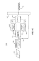
- FIG. 1C illustrates an example of a data flow 130 that produces constrained encoded data 132 . Similar to the data flow 100 of FIG. 1B , a systematic ECC (Error Correction Code) is applied to each of a plurality of data blocks of the data 135 . In the data flow 130 , however, a desired constraint insertion is determined 138 . The determination of the constraint insertion 138 may be based on, for example, a desired output data type, a desired minimum Hamming weight, or some other suitable condition or characteristic desired of the data to be delivered via the channel 20 .
- ECC Error Correction Code
- the desired constraint is a desired minimum Hamming weight for a systematic error correction code.
- the determination of the constraint insertion 138 is based on the error correction code property of minimum distances, e.g., error correction codes can successfully detect erroneous sequences that are at least dmin distant from the encoded bit sequence.
- error correction codes with a minimum Hamming distance dmin between code vectors or words, a one bit change in a sequence of original information bits 135 translates into an at least dmin ⁇ 1 flip in the required dmin parity bits appended to the original information bits.
- pivot data is added to the original data 135 by a pivot bit inserter 140 to generate parity that is at least dmin ⁇ 1 away from an all-zero vector.
- the pivot data may include one or more pivot bits.
- the one or more pivot bits may be manipulated so that the desired constraint may be met by the output data.
- pivot bit inserter 140 results in the formation of appended data blocks.
- the pivot data or one or more pivot bits each may be appended or inserted into the data block 135 at any suitable bit position, and are not required to be appended to the end of the data block 135 .
- appending refers to adding to the beginning or to the end of a block, or inserting within the block at one or more locations, or combinations thereof.
- Each inserted pivot bit is assigned a “1” or a “0” value.
- the appended data block is encoded with one pivot bit value by an encoded data generator 142 , and is separately encoded with the other pivot bit value by the same or a different encoded data generator 145 .
- the encoded data generators 142 , 145 are error correction encoders or ECC encoders (such as embodiments of encoder 22 of FIG. 1A ) that apply error correction to data that is to be transmitted, however, other encoded data generators may be contemplated and used in conjunction with embodiments of the present disclosure.
- the pivot bit value may indicate an application or an omission of a transformation to the data 135 to be performed in conjunction with the error correction coding at the blocks 142 and 145 .
- the transformation can be any suitable mapping function that is applied to the data block.
- a transformation can include simply appending the pivot bit(s) to the corresponding data block.
- the transformation may be a masking function, for example, XOR-ing the data block with a mask of all “1”s, all “0”s, or a combination of “1”s and “0”s.
- the original data 135 may be XOR-ed with a mask of all “1”s at the encoded data generator 142 , and if the pivot bit is assigned the “0” value, the original data 135 may not be XOR-ed with the mask of all “1”s at the encoded data generator 145 .
- the transformation may be a swap function.
- a first portion of the data 135 is swapped with a second portion of the data 135 .
- the pivot bit is assigned the “0” value, the original data 135 may remain unchanged.
- transformations are not limited to the examples described above. Other suitable transformations can be utilized and can be indexed by one or more pivot bits.
- a selector 148 makes a selection between the parity data corresponding to the pivot bit of value “0” and the parity data corresponding to the pivot bit of value “1.”
- the parity data that best meets the desired constraint may be selected by the selector 148 , and the selected parity data is multiplexed at a multiplexer 150 with the original data 152 .
- the data flow 130 produces (for each block of data 135 ) encoded data 132 that meets the desired constraint or condition 138 in addition to maintaining the desired error correction strategy 142 , 145 (e.g., calculation of parity, etc.).
- the encoded data 132 also may include an indication of the transformation that was performed (if performed).
- the encoded data may include the pivot bit corresponding to the selection made at the selector 148 .
- the at least one pivot bit does not influence error correction coding of the data 135 (e.g., as performed by the encoded data generators 142 , 145 ), but instead effects the generated parity of the encoded data (as selected by the selector 148 ) to have the desired constraint.
- a data block is entirely encoded by the encoded data generator 142 and/or 145 and is output as constrained encoded data 132 without needing to be multiplexed 150 with the original data 152 .
- the multiplexing block 150 may be omitted.
- inserting pivot bits at block 140 may also be omitted, such as when anon-systematic error correction code itself determines parity to meet a desired constraint.
- multiple pivot bits can be inserted by the pivot bit inserter 140 .
- each of the pivot bits can be separately assigned different values.
- each of the multiple pivot bits may index a different transformation.
- a first permutation/combination of multiple pivot bits and their values indexes a particular, single transformation, and different permutations/combinations of the multiple pivot bits and their values index corresponding different, transformations.
- the indicated transformation(s) may be applied prior to error correction.
- a particular permutation of pivot bits and their values that is closest to the desired constraint may be selected from the multiple permutations.
- two separate ECC encoders 142 , 145 may not be necessary.
- computing each of n permutations or combinations of pivot bits in parallel by n ECC encoders instead of computing each of n permutations or combinations of pivot bits are sequentially performed by a single ECC encoder, and the pivot bit value(s) are modified for each computation. When a permutation or combination is discovered that meets the desired output constraint, it is selected by selector 148 . In some embodiments, a combination of both sequential and parallel ECC computing is utilized.
- both the data flow 100 and the data flow 130 generate encoded data ( 102 , 132 , respectively) with a same number of parity bits.
- the data flow 130 constrains the parity bits so that the output data 132 meets or is close to the desired output constraint.
- the data flow 130 produces output data that is better optimized for the data channel and/or the data receiver as compared with the data flow 100 .
- the one or more ECC encoders 142 , 145 utilize a linear, systematic ECC code (e.g., BCH code).
- a linear, systematic ECC code e.g., BCH code
- BCH code a linear, systematic ECC code
- a transformation corresponding to an opposite value of the pivot bit may simply be computed via an XOR operation (i.e., “exclusive-or,” denoted by the symbol “ ⁇ circumflex over (x) ⁇ ”).
- XOR operation i.e., “exclusive-or,” denoted by the symbol “ ⁇ circumflex over (x) ⁇ ”.
- 001 may be pre-determined and stored, and may be represented as M.
- the parity bits X corresponding to the original data+0 are computed by the ECC encoder. Due to the linearity of BCH codes, the parity bits Y corresponding to the original data+1 can be computed by the expression: X XOR M. A selection between X and Y s then made at selector 148 to determine which is closer to the desired constraint.
- FIG. 2 illustrates an example of an output data stream 200 that meets a desired output constraint in a piece-wise manner.
- the data stream 200 can be an output of the data flow 130 of FIG. 1C , and can be generated by the encoder 22 of FIG. 1A .
- the output data stream 200 illustrates only two blocks of data 205 a , 205 b , but any number of data blocks may be used.
- the data blocks 205 a , 205 b as shown in FIG. 2 are each encoded according to a same error correction coding scheme, but each is transformed according to a different transformation to satisfy an output constraint.
- the data block 205 a is transformed by a first combination of pivot bits (e.g., bits 215 a , 215 h and 215 c ) and their values
- the data block 205 b is transformed by a different combination of pivot bits (e.g., bits 215 d , 215 e ) and their values.
- both data blocks 205 a , 205 b still meet the desired output constraint.
- the first combination of pivot bits ( 215 a , 215 b and 215 c ) and the second combination of pivot bits ( 215 d , 215 e ) shown in FIG. 2 are exemplary only, and any combination of any number of pivot bits in any bit positions may be included in each of the data blocks 205 a , 205 b.
- each data block 205 a , 205 b is a corresponding indicator block ( 208 a , 208 b , respectively).
- Each indicator block 208 a , 208 b may include a same number of bits (e.g., 12 bits, 8 bits, 4 bits, etc.) or a different number of bits.
- Each indicator block 208 a , 208 b indicates a different transformation that is applied to its corresponding data block 205 a , 205 b during encoding.
- the decoder 25 begins to decode the data stream 200 , it strips off the indicator bits 208 a .
- Decoding corresponding to the applied encoding scheme at the transmitter 12 is performed, including stripping off any added pivot bits, so that the original data corresponding to user block 205 a is recovered provided the channel has not introduced too many errors.
- the decoder 25 Based on the indicator bits 208 a , the decoder 25 applies an inverse of the transformation indicated by bits 208 a to recover the original data block.
- the indicator 208 b is stripped off, decoding is performed, and an inverse of the transformation indicated by the indicator block 208 b is applied to the data block 205 b .
- a mapping of indicators to different transformations can be pre-defined and shared a priori between the transmitter 12 and the receiver 15 , for example.
- indicators such as indicators 208 a , 208 b may correspond to masks.
- “Indicator 1 ” 208 a corresponds to “Mask A” 210 a
- “Indicator 2 ” 208 b corresponds to “Mask B” 210 b
- the relationships between indicators 208 a , 208 b and masks 210 a , 210 b may be pre-defined and shared a priori between the transmitter 12 and the receiver 15 , for example.
- each indicator may correspond to one particular mask. Alternatively, more than one different indicator may correspond to a same mask.
- the decoder 25 need only XOR ( 212 a , 212 b ) each data block 205 a , 205 b with an appropriate mask 210 a , 210 b as indicated by the corresponding indicator 208 a , 208 b . In this manner, the decoder 25 may reverse the transformation that was applied by the encoder 22 .
- FIG. 3 is a flow diagram of an embodiment of a method 300 for encoding data to meet a desired output constraint. Embodiments of the method 300 may be used, for example, in conjunction with the system 10 of FIG. 1A , the data flow 130 of FIG. 1C , and the data blocks 200 of FIG. 2 .
- a data block is received.
- Different data blocks may be of the same length or of differing lengths.
- At 308 at least one pivot bit is added to the received data block.
- the at least one pivot bit is inserted into at any suitable bit position in the original block (e.g., appended to the beginning, appended to the end, and/or inserted within). If more than one pivot bit is inserted, in some embodiments, some or all of the pivot bits are each inserted at different bit positions. In other embodiments, some or all of the pivot bits are inserted as a contiguous sub-block.
- the added pivot bit(s) are set o different values, and at 316 , the differently-valued pivot bits are used to form different encoded data block candidates. For example, if a single pivot bit is added, it is set to “1” and a first encoded data block candidate is generated. Also, the single pivot bit is set to “0” and a second encoded data block candidate is generated. If multiple pivot bits are added, various combinations of possible bit values for the multiple pivot bits are set, and corresponding encoded data block candidates are generated. For example, if two pivot bits are added, then a different encoded data block is generated for each of the pivot bit value combinations: 00, 01, 10, and 11.
- each pivot bit corresponds to a different transformation, where one value of the pivot bit may indicate “apply the transformation,” and another value of the pivot bit may indicate “do not apply the transformation.”
- a particular combination of pivot bit values may correspond to a single particular transformation.
- both individual and group pivot bit indications of transformations are used concurrently. For example, pivot bit A having a value of “1” may indicate flipping a quartile of the bits of the data block. Pivot bit B having a value of “1” may indicate XOR-ing bits with a mask of “1”s.
- Pivot bits C-F may each correspond to a particular quartile of the data block. If pivot bits A, C and D are all set to “1”, the indicated transformation includes flipping the first quartile of the data block with the second quartile. If pivot bits B and F are set, the indicated transformation includes XOR-ing masking the last quartile of the data block with a mask of “1”s. Of course, these examples are only illustrative and other suitable transformations and combinations of transformations may be utilized.
- multiple data block candidates can be generated in parallel, where a separate error correction block (e.g., multiple ECC blocks) generates each encoded data block candidate.
- each encoded data block candidate may be generated sequentially, where a same error correction block (e.g., a single ECC block) generates each encoded data block one at a time.
- a combination of parallel and sequential generation of the set of data block candidates is utilized.
- the encoded data block candidates are evaluated against a desired constraint.
- a desired constraint is a desired condition or characteristic of the encoded data block.
- the desired condition or characteristic of the output data can be based upon the channel to be used and/or the receiving device, for example. Similar to 316 , evaluating each encoded data block candidate against the desired constraint 320 may be performed in parallel, sequentially, or combination of parallel and sequential.
- a particular encoded data block candidate that meets the desired constraint is selected.
- an encoded data block candidate that best meets the desired constraint is selected from all possible encoded data block candidates after all have been evaluated 320 .
- an encoded data block candidate that sufficiently (but perhaps not optimally) meets the desired constraint is selected without evaluating 320 each and every candidate. For example, if encoded data block candidates are evaluated sequentially at 320 , a first encoded data block candidate that meets the desired constraint is selected at 324 , and any remaining candidates are not evaluated after the selection of the first, sufficiently constrained encoded data block candidate.
- the selected encoded data block (or in other words, the encoded, constrained original data block) is output.
- the selected encoded data block may be sent to a transmit path for modulation and transmission via an antenna or antennas.
- the selected encoded data block is sent to a write channel for writing the encoded data to a storage medium.
- the method 300 is executed for each data block that is desired to be transmitted. For example, the method 300 operates on a first data block, and then again on each subsequent data block until all data blocks corresponding to a totality of the data has been constrained, encoded and output.
- the method 300 may be easily adapted when more than one constraint is desired to be met. For example, a first pass of the method 300 may be executed on a particular data block to meet a first desired constraint. Then, a second pass of the method 300 may be executed on the same data block to meet a next desired constraint. In another example, a single pass of the method 300 may be executed on the particular data block, but 320 may evaluate encoded data blocks against all desired constraints simultaneously. Other adaptations of the method 300 to accommodate multiple desired constraints will be appreciated by one of ordinary skill in the art in view of the disclosure and teachings herein.
- the method 300 can be utilized in conjunction with systematic or non-systematic error correction codes.
- the method 300 includes multiplexing parity data with the original data block (not shown in FIG. 3 ), such as illustrated by 150 , 152 of FIG. 1C .
- FIG. 4 is a flow diagram of an embodiment of a method 400 for encoding data to meet a desired constraint.
- the method 400 may be used, for example, in conjunction with the system 10 of FIG. 1A , the data flow 130 of FIG. 1C , and the data blocks 200 of FIG. 2 .
- At 408 at least one pivot bit is added to the originally received data block to form an appended data block.
- the at least one pivot bit has a combination of at least one value corresponding to a transformation.
- the appended data block is transformed according to the transformation corresponding to the value(s) of pivot bit(s) added at 408 .
- each pivot bit may correspond to a different transformation, where one value of the pivot bit may indicate “apply the transformation” and another value of the pivot bit may indicate “do not apply the transformation.”
- a particular combination of pivot bits and their associated values may correspond to a single particular transformation.
- both individual and group pivot bit indications of transformations may be used concurrently.
- an error correction code is applied to the transformed data block.
- Any suitable error correction code may be applied at 415 , such as systematic error correction codes (e.g., data plus checksum, BCH, Reed-Solomon, etc.) or non-systematic error correction codes (e.g., non-systematic convolutional codes, rateless erasure codes or fountain codes such as Raptor, among others).
- the encoded data block it is determined whether or not a desired constraint is met by the encoded data block. If the encoded data block meets the desired constraint (as determined at 418 ), it is output to be transmitted 420 and the method 400 ends. If the encoded data block does not meet the desired constraint (as determined at 418 ), a different combination of pivot bit(s) and/or pivot bit value(s) is selected at 424 . Then, the flow reverts back to the 408 . In this fashion, the method 400 includes potentially repeatedly inserting various combinations of pivot bit(s) into the original data block and evaluating the resulting encoded data block until a combination of pivot bit(s) is discovered that sufficiently meets the desired constraint (e.g., the condition at 418 is fulfilled). Upon its discovery, the particular encoded data block is output at 420 as it is sufficiently constrained to meet the desired condition, and the method 400 ends.
- the method 400 may be applied afresh to each data block that is desired to be transmitted. For example, the method 400 may operate on a first data block, and then again on each subsequent data block.
- the method 400 may be adapted to scenarios where multiple desired output constraints are desired. For example, at 418 each encoded data block may be evaluated against all desired output constraints simultaneously, for example. Other adaptations for multiple desired output constraints will be recognized by one of ordinary skill in the art in view of the disclosure and teachings herein.
- the method 400 may not ensure that the transmitted, constrained data at 420 is the most optimally constrained data block. If a system desires optimization of a constraint, embodiments of the method 300 may be more appropriate as a larger set of potential encoded data block candidates may be considered prior to selection. If a system desires its constrained output to be “good enough,” the method 400 may be used. Clearly, a tradeoff may exist between a cost and time of processing vs. a level of optimization of constrained data output.
- FIG. 5 is a block diagram of an embodiment of an apparatus 500 for encoding data to meet a desired output constraint.
- Embodiments of the apparatus 500 may operate in conjunction, for example, with the system 10 of FIG. 1A , the data flow 130 of FIG. 1C , the data blocks 200 of FIG. 2 , the method 300 of FIG. 3 and/or the method 400 of FIG. 4 .
- the apparatus 500 may be implemented in the encoder 22 of a transmitter 12 using a processor executing software instructions, a processor executing firmware instructions, hardware or some combination thereof.
- the apparatus 500 includes an encoded data generator 502 that receives data 504 and generates a plurality of different encoded candidates 514 based on the data 504 .
- the encoded data generator 502 includes a transformer 508 , such as a data transformer, and an ECC encoder 510 .
- the transformer 508 generates at least one transformed version 512 of the data 504 .
- transformer 508 includes a pivot bit inserter (not shown) configured to add one or more pivot bits to the data 504 , and to output transformed versions 512 that includes different values of the one or more pivot bits.
- the one or more pivot bits may be added as a contiguous block into the data 504 , the one or more pivot bits may be individually inserted into any suitable bit position including at the beginning, at the end, or within the data 504 , or a combination of contiguous and non-contiguous bit positions may be used.
- the pivot bit inserter assigns a value of “1” or “0” to each pivot bit, and outputs the transformed versions 512 to the ECC encoder 510 .
- the one or more combinations of pivot bits may each have a same or different number of total bits. Furthermore, the values of the pivot bits differ across the one or more combinations of appended data.
- the pivot bit inserter may output a first combination of appended data that includes the original data 504 appended with a contiguous block of three pivot bits that are each set to the bit value “1,” and the pivot bit inserter may output a second combination of appended data of the original data 504 with five added pivot bits, one pivot bit inserted at every second bit position, where every other of the five added pivot bits is set to the bit value “1.”
- a pivot bit or combination of pivot bits corresponds to a transformation to be performed on the data 504 by the transformer 508 , where a pivot bit value of “1” indicates “apply the transformation” and a pivot bit value of “0” indicates “do not apply the transformation.” Examples of possible transformations may include those discussed with respect to FIG. C.
- the transformed versions 512 are provided to the ECC encoder 510 .
- the ECC encoder 510 is a single ECC encoder, and each of the combinations of appended data output from the transformer 508 is passed sequentially to the single ECC encoder 510 .
- the ECC encoder 510 includes multiple single ECC encoders operating in parallel, and at least some of the transformed versions 512 are provided in parallel to the multiple ECC encoders 510 .
- the ECC encoder 510 applies any suitable error correction coding. Different encoded candidates 514 corresponding to different pivot values are generated by the ECC encoder 510 . In some embodiments, the ECC encoder 510 may use a systematic error correction code so that each encoded candidate 514 includes the original data 504 and parity data. In other embodiments, the ECC encoder 510 may use a non-systematic error correction code.
- the order of the transformer 508 and the ECC encoder 510 may be reversed.
- the data 504 may be encoded, and then different encoded candidates 514 can be generated by transforming the ECC encoded data.
- a pivot bit inserter may insert one or more pivot bits into the data 504 , each with a value of zero for example, and the ECC encoder 510 generates an encoded version of the data 504 appended with the one or more pivot bits.
- the transformer 508 can then transform the encoded version of the data 504 appended with the one or more pivot bits into a plurality of encoded candidate 514 corresponding to different values of the one or more pivot bits.
- the ECC encoder 510 delivers the different encoded candidates 514 to a selector 515 .
- the different encoded candidates 512 can be delivered sequentially, in parallel, or a combination of sequential and parallel delivery.
- the selector 515 is configured to select one of the different encoded candidates 514 to output as encoded data 518 to be transmitted.
- the selector 515 includes an evaluator 520 configured to calculate a measurement for use by the selector 515 to compare the different encoded candidates 512 .
- the calculations performed by the evaluator 520 provide a measurement related to the desired constraint on output data.
- the evaluator 520 may calculate a distance between each candidate 512 and a desired Hamming weight.
- the evaluator 502 may calculate a total number of “1”s in each candidate 512 .
- Other suitable measurements or calculations may be determined by the evaluator 520 .
- the selector 515 determines a most suitable candidate from the candidates 512 and outputs the encoded data 518 to be transmitted.
- the most suitable candidate is the candidate that meets or is closest to the desired output constraint.
- FIGS. 3 and 4 and the apparatus of FIG. 5 may be implemented using hardware, a processor executing firmware instructions, a processor executing software instructions, or any combination thereof.
- the software or firmware instructions may be stored in a memory associated with the processor. More generally, the software or firmware instructions may be stored in any computer readable storage medium such as on a magnetic disk, an optical disk, or other storage medium, in a RAM or ROM or flash memory, processor, tape drive, etc.
- the software or firmware may be delivered to a user or a system via any known or desired delivery method including, for example, on a computer readable disk or other transportable computer storage mechanism or via communication media.
- Communication media typically embodies computer readable instructions, data structures, program modules or other data in a modulated data signal such as a carrier wave or other transport mechanism.
- modulated data signal means a signal that has one or more of its characteristics set or changed in such a manner as to encode information in the signal.
- communication media includes wired media such as a wired network or direct-wired connection, and wireless media such as acoustic, radio frequency, infrared and other wireless media.
- the software or firmware may be delivered to a user or a system via a communication channel such as a telephone line, a DSL line, a cable television line, a fiber optics line, a wireless communication channel, the Internet, etc. (which are viewed as being the same as or interchangeable with providing such software via a transportable storage medium).
- the software or firmware may include machine readable instructions that are capable of causing one or more processors to perform various acts.
- the hardware may comprise one or more of discrete components, an integrated circuit, an application-specific integrated circuit (ASIC), etc.
- ASIC application-specific integrated circuit
Landscapes
- Engineering & Computer Science (AREA)
- Computer Networks & Wireless Communication (AREA)
- Signal Processing (AREA)
- Theoretical Computer Science (AREA)
- Physics & Mathematics (AREA)
- Quality & Reliability (AREA)
- General Engineering & Computer Science (AREA)
- General Physics & Mathematics (AREA)
- Probability & Statistics with Applications (AREA)
- Error Detection And Correction (AREA)
Abstract
Description
Claims (18)
Priority Applications (2)
| Application Number | Priority Date | Filing Date | Title |
|---|---|---|---|
| US12/701,895 US8418031B1 (en) | 2009-02-09 | 2010-02-08 | Systems and methods for encoding data to meet an output constraint |
| US13/855,879 US8910024B1 (en) | 2009-02-09 | 2013-04-03 | Systems and methods for encoding data to meet an output constraint |
Applications Claiming Priority (2)
| Application Number | Priority Date | Filing Date | Title |
|---|---|---|---|
| US15102009P | 2009-02-09 | 2009-02-09 | |
| US12/701,895 US8418031B1 (en) | 2009-02-09 | 2010-02-08 | Systems and methods for encoding data to meet an output constraint |
Related Child Applications (1)
| Application Number | Title | Priority Date | Filing Date |
|---|---|---|---|
| US13/855,879 Continuation US8910024B1 (en) | 2009-02-09 | 2013-04-03 | Systems and methods for encoding data to meet an output constraint |
Publications (1)
| Publication Number | Publication Date |
|---|---|
| US8418031B1 true US8418031B1 (en) | 2013-04-09 |
Family
ID=47999377
Family Applications (2)
| Application Number | Title | Priority Date | Filing Date |
|---|---|---|---|
| US12/701,895 Expired - Fee Related US8418031B1 (en) | 2009-02-09 | 2010-02-08 | Systems and methods for encoding data to meet an output constraint |
| US13/855,879 Expired - Fee Related US8910024B1 (en) | 2009-02-09 | 2013-04-03 | Systems and methods for encoding data to meet an output constraint |
Family Applications After (1)
| Application Number | Title | Priority Date | Filing Date |
|---|---|---|---|
| US13/855,879 Expired - Fee Related US8910024B1 (en) | 2009-02-09 | 2013-04-03 | Systems and methods for encoding data to meet an output constraint |
Country Status (1)
| Country | Link |
|---|---|
| US (2) | US8418031B1 (en) |
Cited By (5)
| Publication number | Priority date | Publication date | Assignee | Title |
|---|---|---|---|---|
| US20110055641A1 (en) * | 2009-08-26 | 2011-03-03 | Seagate Technology Llc | Data corruption detection |
| US8910024B1 (en) * | 2009-02-09 | 2014-12-09 | Marvell International Ltd. | Systems and methods for encoding data to meet an output constraint |
| CN105182752A (en) * | 2015-09-17 | 2015-12-23 | 浙江大学 | Rapid design method of dilute acetone distillation industry dynamic optimization control layer output constraint |
| CN105223812A (en) * | 2015-09-17 | 2016-01-06 | 浙江大学 | A kind of method for designing of rare acetone rectifying industrial dynamics optimal control layer output constraint |
| TWI672930B (en) * | 2018-02-12 | 2019-09-21 | 瑞昱半導體股份有限公司 | Network data prediction method, network data processing device and network data processing method |
Citations (9)
| Publication number | Priority date | Publication date | Assignee | Title |
|---|---|---|---|---|
| US3078443A (en) * | 1959-01-22 | 1963-02-19 | Alan C Rose | Compound error correction system |
| US5579303A (en) * | 1994-09-28 | 1996-11-26 | Nec Corporation | Data transmission apparatus |
| US6044485A (en) * | 1997-01-03 | 2000-03-28 | Ericsson Inc. | Transmitter method and transmission system using adaptive coding based on channel characteristics |
| US6182264B1 (en) * | 1998-05-22 | 2001-01-30 | Vlsi Technology, Inc. | Smart dynamic selection of error correction methods for DECT based data services |
| US6201811B1 (en) * | 1998-03-24 | 2001-03-13 | Telefonaktiebolaget Lm Ericsson (Publ) | Transferring Identifier information in a telecommunications system |
| US6400728B1 (en) * | 1998-09-09 | 2002-06-04 | Vlsi Technology, Inc. | Method and system for detecting user data types in digital communications channels and optimizing encoding-error correction in response thereto |
| US6665831B1 (en) * | 1999-03-31 | 2003-12-16 | Fujitsu Limited | Unequal error protection in multi-carrier transmission |
| US6735735B1 (en) * | 1999-07-12 | 2004-05-11 | Hitachi, Ltd. | Forward error correcting code encoding equipment, forward error correcting code decoding equipment, and transmission apparatus |
| US6757860B2 (en) * | 2000-08-25 | 2004-06-29 | Agere Systems Inc. | Channel error protection implementable across network layers in a communication system |
Family Cites Families (4)
| Publication number | Priority date | Publication date | Assignee | Title |
|---|---|---|---|---|
| US20050249127A1 (en) | 2004-05-10 | 2005-11-10 | Lucent Technologies, Inc. | Method for subcarrier allocation |
| JP2006094003A (en) | 2004-09-22 | 2006-04-06 | Ntt Docomo Inc | Mobile communication system, apparatus and method for allocating frequency band |
| DE602005008422D1 (en) | 2005-08-01 | 2008-09-04 | Ntt Docomo Inc | A method for forwarding information by means of a first channel to a second channel and radio relay device |
| US8418031B1 (en) * | 2009-02-09 | 2013-04-09 | Marvell International Ltd. | Systems and methods for encoding data to meet an output constraint |
-
2010
- 2010-02-08 US US12/701,895 patent/US8418031B1/en not_active Expired - Fee Related
-
2013
- 2013-04-03 US US13/855,879 patent/US8910024B1/en not_active Expired - Fee Related
Patent Citations (9)
| Publication number | Priority date | Publication date | Assignee | Title |
|---|---|---|---|---|
| US3078443A (en) * | 1959-01-22 | 1963-02-19 | Alan C Rose | Compound error correction system |
| US5579303A (en) * | 1994-09-28 | 1996-11-26 | Nec Corporation | Data transmission apparatus |
| US6044485A (en) * | 1997-01-03 | 2000-03-28 | Ericsson Inc. | Transmitter method and transmission system using adaptive coding based on channel characteristics |
| US6201811B1 (en) * | 1998-03-24 | 2001-03-13 | Telefonaktiebolaget Lm Ericsson (Publ) | Transferring Identifier information in a telecommunications system |
| US6182264B1 (en) * | 1998-05-22 | 2001-01-30 | Vlsi Technology, Inc. | Smart dynamic selection of error correction methods for DECT based data services |
| US6400728B1 (en) * | 1998-09-09 | 2002-06-04 | Vlsi Technology, Inc. | Method and system for detecting user data types in digital communications channels and optimizing encoding-error correction in response thereto |
| US6665831B1 (en) * | 1999-03-31 | 2003-12-16 | Fujitsu Limited | Unequal error protection in multi-carrier transmission |
| US6735735B1 (en) * | 1999-07-12 | 2004-05-11 | Hitachi, Ltd. | Forward error correcting code encoding equipment, forward error correcting code decoding equipment, and transmission apparatus |
| US6757860B2 (en) * | 2000-08-25 | 2004-06-29 | Agere Systems Inc. | Channel error protection implementable across network layers in a communication system |
Non-Patent Citations (2)
Cited By (7)
| Publication number | Priority date | Publication date | Assignee | Title |
|---|---|---|---|---|
| US8910024B1 (en) * | 2009-02-09 | 2014-12-09 | Marvell International Ltd. | Systems and methods for encoding data to meet an output constraint |
| US20110055641A1 (en) * | 2009-08-26 | 2011-03-03 | Seagate Technology Llc | Data corruption detection |
| US8914697B2 (en) * | 2009-08-26 | 2014-12-16 | Seagate Technology Llc | Data corruption detection |
| CN105182752A (en) * | 2015-09-17 | 2015-12-23 | 浙江大学 | Rapid design method of dilute acetone distillation industry dynamic optimization control layer output constraint |
| CN105223812A (en) * | 2015-09-17 | 2016-01-06 | 浙江大学 | A kind of method for designing of rare acetone rectifying industrial dynamics optimal control layer output constraint |
| CN105182752B (en) * | 2015-09-17 | 2018-04-27 | 浙江大学 | A kind of Fast design method of dilute acetone rectifying industrial dynamics optimal control layer output constraint |
| TWI672930B (en) * | 2018-02-12 | 2019-09-21 | 瑞昱半導體股份有限公司 | Network data prediction method, network data processing device and network data processing method |
Also Published As
| Publication number | Publication date |
|---|---|
| US8910024B1 (en) | 2014-12-09 |
Similar Documents
| Publication | Publication Date | Title |
|---|---|---|
| JP5863200B2 (en) | Encoding and decoding using elastic codes with flexible source block mapping | |
| US8910024B1 (en) | Systems and methods for encoding data to meet an output constraint | |
| TWI381273B (en) | Adaptive systems and methods for storing and retrieving data to and from memory cells | |
| US7425905B1 (en) | Circuits, architectures, systems, methods, algorithms and software for conditional modulation coding | |
| US7409622B1 (en) | System and method for reverse error correction coding | |
| US8161347B1 (en) | Interleaving parity bits into user bits to guarantee run-length constraint | |
| US20070300123A1 (en) | Error-Correcting Encoding Apparatus | |
| JPH11508712A (en) | Method and apparatus for protecting data in a disk drive buffer | |
| KR20090026238A (en) | Signal segmentation method and crc attachment method for reducing undetected error | |
| CN101542914A (en) | Reliability metric generation for trellis-based detection and/or decoding | |
| JP2016527832A (en) | System, method, and computer program for combined error and erasure decoding for product codes | |
| RU2005132772A (en) | METHOD FOR CODING-DECODING INFORMATION IN DATA TRANSFER SYSTEMS | |
| CN101779379A (en) | encoding and decoding using generalized concatenated codes (gcc) | |
| US8365053B2 (en) | Encoding and decoding data using store and exclusive or operations | |
| US20170054455A1 (en) | Coding schemes including alternative codings for a single code construct | |
| US9571231B2 (en) | In-band status encoding and decoding using error correction symbols | |
| US9252815B2 (en) | Extension of product codes with applications to tape and parallel channels | |
| US8910013B1 (en) | Methods and apparatus for providing multi-layered coding for memory devices | |
| RU2379841C1 (en) | Decoder with erasure correction | |
| US9236890B1 (en) | Decoding a super-code using joint decoding of underlying component codes | |
| KR102109589B1 (en) | Overhead minimized coding technique and hardware implementation method including transmission/reception error correction technique for high-speed serial interface | |
| US11362679B2 (en) | Method and apparatus for generating redundant bits for error detection | |
| JP3628013B2 (en) | Signal transmitting apparatus and encoding apparatus | |
| RU2571605C2 (en) | Method for noiseless encoding and decoding of digital data | |
| US20180091174A1 (en) | Progressive polar channel coding in flash memory and communications |
Legal Events
| Date | Code | Title | Description |
|---|---|---|---|
| AS | Assignment |
Owner name: MARVELL INTERNATIONAL LTD., BERMUDA Free format text: ASSIGNMENT OF ASSIGNORS INTEREST;ASSIGNOR:MARVELL SEMICONDUCTOR, INC.;REEL/FRAME:023918/0169 Effective date: 20100209 Owner name: MARVELL SEMICONDUCTOR, INC., CALIFORNIA Free format text: ASSIGNMENT OF ASSIGNORS INTEREST;ASSIGNORS:YANG, XUESHI;BURD, GREGORY;SIGNING DATES FROM 20100203 TO 20100204;REEL/FRAME:023918/0156 |
|
| STCF | Information on status: patent grant |
Free format text: PATENTED CASE |
|
| FPAY | Fee payment |
Year of fee payment: 4 |
|
| AS | Assignment |
Owner name: CAVIUM INTERNATIONAL, CAYMAN ISLANDS Free format text: ASSIGNMENT OF ASSIGNORS INTEREST;ASSIGNOR:MARVELL INTERNATIONAL LTD.;REEL/FRAME:052918/0001 Effective date: 20191231 |
|
| AS | Assignment |
Owner name: MARVELL ASIA PTE, LTD., SINGAPORE Free format text: ASSIGNMENT OF ASSIGNORS INTEREST;ASSIGNOR:CAVIUM INTERNATIONAL;REEL/FRAME:053475/0001 Effective date: 20191231 |
|
| FEPP | Fee payment procedure |
Free format text: MAINTENANCE FEE REMINDER MAILED (ORIGINAL EVENT CODE: REM.); ENTITY STATUS OF PATENT OWNER: LARGE ENTITY |
|
| LAPS | Lapse for failure to pay maintenance fees |
Free format text: PATENT EXPIRED FOR FAILURE TO PAY MAINTENANCE FEES (ORIGINAL EVENT CODE: EXP.); ENTITY STATUS OF PATENT OWNER: LARGE ENTITY |
|
| STCH | Information on status: patent discontinuation |
Free format text: PATENT EXPIRED DUE TO NONPAYMENT OF MAINTENANCE FEES UNDER 37 CFR 1.362 |
|
| FP | Lapsed due to failure to pay maintenance fee |
Effective date: 20210409 |