US8412256B2 - Inter-cell interference coordination method and apparatus for wireless communication system - Google Patents
Inter-cell interference coordination method and apparatus for wireless communication system Download PDFInfo
- Publication number
- US8412256B2 US8412256B2 US12/763,493 US76349310A US8412256B2 US 8412256 B2 US8412256 B2 US 8412256B2 US 76349310 A US76349310 A US 76349310A US 8412256 B2 US8412256 B2 US 8412256B2
- Authority
- US
- United States
- Prior art keywords
- interference
- base station
- cell
- prb
- resource block
- Prior art date
- Legal status (The legal status is an assumption and is not a legal conclusion. Google has not performed a legal analysis and makes no representation as to the accuracy of the status listed.)
- Active, expires
Links
Images


Classifications
-
- H—ELECTRICITY
- H04—ELECTRIC COMMUNICATION TECHNIQUE
- H04W—WIRELESS COMMUNICATION NETWORKS
- H04W52/00—Power management, e.g. TPC [Transmission Power Control], power saving or power classes
- H04W52/04—TPC
- H04W52/18—TPC being performed according to specific parameters
- H04W52/24—TPC being performed according to specific parameters using SIR [Signal to Interference Ratio] or other wireless path parameters
- H04W52/243—TPC being performed according to specific parameters using SIR [Signal to Interference Ratio] or other wireless path parameters taking into account interferences
-
- H—ELECTRICITY
- H04—ELECTRIC COMMUNICATION TECHNIQUE
- H04B—TRANSMISSION
- H04B15/00—Suppression or limitation of noise or interference
-
- H—ELECTRICITY
- H04—ELECTRIC COMMUNICATION TECHNIQUE
- H04W—WIRELESS COMMUNICATION NETWORKS
- H04W72/00—Local resource management
- H04W72/20—Control channels or signalling for resource management
- H04W72/27—Control channels or signalling for resource management between access points
-
- H—ELECTRICITY
- H04—ELECTRIC COMMUNICATION TECHNIQUE
- H04W—WIRELESS COMMUNICATION NETWORKS
- H04W72/00—Local resource management
- H04W72/50—Allocation or scheduling criteria for wireless resources
- H04W72/54—Allocation or scheduling criteria for wireless resources based on quality criteria
- H04W72/541—Allocation or scheduling criteria for wireless resources based on quality criteria using the level of interference
Definitions
- the present invention relates generally to wireless communications and, in particular, to an inter-cell interference coordination method and apparatus for mitigating inter-cell interference in a wireless communication system by using interference coordination information exchanged among neighbor base stations.
- RNTP Relative Narrowband Transmit (TX) Power (RNTP) indication is defined for DownLink (DL) Inter-Cell Interference Coordination (ICIC).
- An RNTP message includes a plurality Information Elements (IEs) such as an RNTP Per Physical Resource Block (PRB), RNTP Threshold, Number Of Cell-specific Antenna Ports (P_B), and Physical Downlink Control CHannel (PDCCH) Interference Impact.
- IEs Information Elements
- FIG. 1 illustrates the arrangement of RNTP Per PRB in a normal power control message for use in a conventional wireless communication system.
- the RNTP Per PRB's have a value ‘0’ or ‘1’ and constitute a bitmap.
- the i th value of the bitmap corresponds to the i th PRB.
- the value ‘0’ indicates transmit power not exceeding an RNTP threshold and the value ‘1’ indicates transmit power exceeding the RNTP Threshold.
- the RNTP Per PRB is set to 1, this does not indicate that power is to be allocated greater than the RNTP Threshold.
- the power less than the RNTP Threshold is allocated, this does not indicate that the RNTP Per PRB value changes immediately from 1 to 0. This is because the RNTP message is transmitted at a time interval of at least 100 ms and a PRB allocation policy is transmitted to neighbor cells during the interval.
- FFR Frequency Reuse Factor 3
- FFR Flexible Frequency Reuse
- FIGS. 2 and 3 illustrate power control message transmission schemes used in the conventional wireless communication system.
- FIG. 2 illustrates conventional implementations of FRF 3 and FFR when the RNTP Threshold has a negative decibel ( ⁇ dB) value. If the RNTP Threshold has a ⁇ dB value and the RNTP Per PRB is set to 0, then there is no power allocation and thus no transmission.
- ⁇ dB decibel
- the base station 1 uses only the PRB[ 0 ] and PRB[ 1 ] resource blocks, the base station allocates only the PRB[ 2 ] and PRB[ 3 ] resource blocks, and base station 3 uses only the PRB[ 4 ] and PRB[ 5 ] resource blocks.
- Each base station can allocate the available resource blocks to User Equipments (UEs).
- UEs User Equipments
- each base station allocates one of the available resource blocks to a cell-center UE and the other resource block to a cell-edge UE.
- each base station can use four resource blocks by allocating the single dedicated resource block for the cell-edge UEs and the shared resource blocks for the cell-center UEs.
- the aforementioned resource allocation technique is basic in system 201 .
- each of the base stations 2 and 3 is assigned a dedicated resource block respectively but the base station 1 is not assigned any dedicated resource block. This may occur in case each of the base stations 1 to 3 is not deployed in a cell of hexagonal formation and exists in a normal environment for determining the RNTP in a distributed manner.
- FIG. 3 illustrates implementations of FRF 3 and FFR when the RNTP Threshold has a value that is not ⁇ dB.
- the RNTP Per PRB is set to 0 but does not exceed the RNTP Threshold, it is possible to allocate a resource block.
- each base station allocates the resource blocks of which RNTP Per PRB is set to 1 for the cell-edge UEs and the resource blocks of which RNTP Per PRB is set to 1 the cell-center UEs. This is an actual FFR scheme.
- each base station allocates the power less than the RNTP Threshold to the resource blocks of which RNTP Per PRB is set to 0.
- the dedicated resource blocks can be allocated unfairly as shown in the systems 205 of FIG. 2 and 305 of FIG. 3 .
- the multiple cells use a predetermined number of resource blocks in common as shown in the systems 203 of FIG. 2 and 303 of FIG. 3 , it is difficult to coordinate the inter-cell interference for the shared resource blocks.
- the resource block may not be used by any cell or may be used by all of the cells, since the decision whether to use the resource block is made by scheduler.
- the resource block usage status is not reflected to the scheduling when using the RNTP message for resource block allocation, it is impossible to achieve dynamic inter-cell interference coordination at an interval shorter than 100 ms.
- the RNTP message may be transmitted more frequently and to reflect the scheduling result to determine the RNTP Per PRB values, the resource block allocation policy is rendered useless, resulting in failure of static ICIC during a long term interval.
- the present invention provides an inter-cell interference coordination method for a wireless communication system that is capable of dynamically mitigating inter-cell interference.
- the present invention provides an inter-cell interference coordination method for a wireless communication that is capable of improving the inter-cell interference mitigation gain by reflecting the scheduling result of a base station on the UEs within the cell.
- an inter-cell interference mitigation method for a wireless communication system includes receiving, at a serving base station, power control messages transmitted by neighbor base stations, receiving incoming interference coordination messages transmitted by neighbor base stations, each coordination message including interference indicators of resource blocks, allocating the resource blocks with transmission power per resource block to user equipments served by the base station based on the power control messages and interference coordination messages, generating outgoing interference coordination messages for the respective neighbor base stations based on the resource block allocation result, and transmitting the interference coordination messages to the neighbor base stations, respectively.
- an inter-cell interference mitigation apparatus for a wireless communication system includes a message processor which receives incoming power control messages and interference coordination messages transmitted by neighbor base stations and transmits outgoing interference coordination messages to the neighbor base stations, an interference processor which extracts interference indicators from the incoming interference coordination messages, and a scheduler which allocates resource blocks to user equipments in a cell with transmission power per resource block based on the interference indicators and generates the outgoing interference coordination messages.
- FIG. 1 illustrates the arrangement of RNTP Per PRB in a normal power control message for use in a conventional wireless communication system
- FIGS. 2 and 3 illustrate power control message transmission schemes used in the conventional wireless communication system.
- FIG. 4A illustrates a DL inter-cell interference coordination system to which the present invention is applied
- FIG. 4B illustrates a configuration of a base station of FIG. 4A ;
- FIG. 5 illustrates a transmission format of a DownLink High Interference Indication (DL HII) message according to an embodiment of the present invention
- FIGS. 6A and 6B illustrate a DL HII message generation procedure of an inter-cell interference coordination method according to an embodiment of the present invention
- FIGS. 7A to 7D illustrate a DL HII message transmission principle for supporting the inter-cell interference coordination method according to an embodiment of the present invention
- FIGS. 8A to 8D illustrate operations of base stations and UEs in the inter-cell interference coordination system according to embodiments of the present invention.
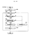
- FIG. 9 illustrates operations of the base stations of the inter-cell interference coordination system.
- a base station receives power allocation messages and interference coordination messages including information on the allocated resource blocks and inter-cell interference from neighbor base stations, allocates resource blocks and transmission power to the UEs within the cell in consideration of the information carried by the power allocation and interference coordination messages, generates an interference coordination message indicating interference probability with each neighbor base station in consideration of the scheduling, and transmit the interference coordination message to the corresponding neighbor base station.
- the interference coordination message generation procedure includes analyzing the individual resource blocks and checking whether the resource blocks are in use, analyzing resource blocks in use, comparing the Reference Signal Received Power (RSRP) of a target cell with an RSRP threshold (RSRP_th), and generating the interference coordination message having a usage indicator set to “interference state” for the PRB of which RSRP greater than the RSRP_th and “use state” for the PRB of which RSRP is not greater than the RSRP_th.
- RSRP Reference Signal Received Power
- the base station does not allocate, to the UEs within the cell, the resource blocks to which the interference coordination message indicates the interference state. That is, the base station allocates the dedicated resource blocks to both the cell-center and cell-edge UEs, the shared resource blocks to the UEs that are not located in the cell edges of the neighbor base stations, and the dedicated resource blocks of the neighbor cells to only the cell-center UEs, and does not allocate the resource block in the interference state.
- LTE Long Term Evolution
- FIG. 4A illustrates a downlink inter-cell interference coordination system to which the present invention is applied
- FIG. 4B illustrates a configuration of a base station of FIG. 4A .
- the inter-cell interference coordination system includes at least two base stations and a plurality of UEs served by one of the base stations.
- a base station can have multiple cells identified by a unique cell identifier, the description is made under the assumption that each base station has a single cell, for purposes of conciseness.
- the inter-cell interference coordination system includes three base stations 100 , 200 , and 300 that are directly interconnected by means of an inter-cell interface without involvement of a core network.
- the inter-cell interface can be an X2 interface.
- Each of the base stations 100 , 200 , and 300 is configured according to the present invention as shown in FIG. 4B .
- each base station includes a message processor 10 for processing the messages exchanged with other base stations through the X2 interface, an ICIC processor for processing operations related to ICIC function, and a scheduler 30 for scheduling resources based on the information collected from the UEs and the neighbor base stations.
- a message processor 10 for processing the messages exchanged with other base stations through the X2 interface
- an ICIC processor for processing operations related to ICIC function
- a scheduler 30 for scheduling resources based on the information collected from the UEs and the neighbor base stations.
- the message processor 10 is configured to receive the RNTP and DL HII messages transmitted by neighbor base stations, and to transmit the RNTP message and HII message generated by the scheduler 30 to the neighbor base stations.
- the HII message processed by the message processor 10 is transferred to the ICIC processor 20 , which extracts power allocation and interference coordination information for use in the PRB and power allocations from the received RNTP messages and DL HII messages by a specific algorithm and provides the extracted information to the scheduler 30 .
- the scheduler 30 allocates the PRBs to the UEs within the cell and assigns power per PRB based on the information provided by the ICIC processor 20 .
- the scheduler 30 also generates the RNTP messages and DL HII messages using location information on the UEs.
- the RNTP and DL HII messages are transferred to the message processor 10 , which transmits the RNTP and DL HII messages to the neighbor base station through the inter-cell interface (i.e. X2 interface).
- the message processor 10 receives the RNTP and DL HII messages transmitted by the neighbor base stations and transmits the RNTP and DL HII messages generated by the scheduler 30 to the neighbor base station.
- the ICIC processor 20 converts the RNTP and DL HII messages to the power allocation and interference coordination information for use in PRB and power allocations.
- the scheduler 30 allocates available PRBs and power to the UEs in its cell based on the power allocation and interference coordination information.
- the scheduler 30 also generates the ICIC message indicating the interference probability with the neighbor base station as a result of its scheduling and transmits the ICIC message to the neighbor base station by means of the message processor 20 .
- the scheduler 30 analyzes the individual PRBs, sets a usage indicator to “use state” for the PRB which is in use and “non-use” for the PRB which is not in use, compares the RSRP of the signal received on the PRB in use state with the RSRP_th, and generates the ICIC message having the usage indicator set to “interference state” for the PRB in use state if the RSRP is greater than or equal to the RSRP_th and “use state” for the PRB in use state if the RSRP is less than the RSRP_th.
- the scheduler 30 does not allocate the PRB of which usage indicator is set to “interference state”. That is, the scheduler 300 allocates its dedicated PRBs for the UEs in its cell, the shared PRBs to the UEs that are not located in the cell edges of the neighbor base stations, and the dedicated PRBs of the neighbor base stations to the cell-center UEs, while excluding the allocation of the PRBs of which usage indicator is set to “interference state”.
- the inter-cell interference coordination method of the present invention is disclosed for dynamically mitigating the inter-cell interference at an interval shorter than 100 ms under the assumption that the RNTP message is transmitted at an interval longer than 100 ms for static ICIC. For this purpose, a DL HII message is introduced in the present invention.
- the inter-cell interference coordination method is devised in consideration of the persistent scheduling service in which the same resource block is periodically allocated to a UE for a predetermined duration.
- FIG. 5 illustrates a transmission format of a DL HII message according to the present invention.
- An RNTP message includes RNTP Per PRB and RNTP Threshold information in the form of a bitmap mapping the resource blocks.
- the DL HII message is formed as a bitmap of values indicating the usage states (non-use state, use state, and interference state) of the corresponding PRBs.
- the following description is made under the assumption that the value “0” indicates the non-use state, “1” indicates the use state, and “2” indicates the interference state.
- N resource blocks are depicted and it is assumed that the PRB[ 0 ] to PRB[ 3 ] and PRB[N ⁇ 1] have the values “1”, “0”, “2”, and “1” respectively. If the usage state value of a resource block is set to “0”, this indicates that the resource block is not in use or is used with the power below a power limit, which can be a threshold of the RNTP of the RNTP message or a separate value.
- the usage state value of the resource block set to “1” indicates that the corresponding resource block is in use with invulnerability to the interference. If the UE allocated the resource block is at the cell center or a cell edge far from the target cell of the DL HII message, the DL HII of the corresponding resource block is set to 1.
- Each base station transmits the DL HII message to a cell-specific manner rather than transmitting the same DL HII message to the neighbor cells. That is, the DL HII messages are generated for the respective target cells with different information values.
- FIGS. 6A and 6B illustrate a DL HII message generation procedure of an inter-cell interference coordination method according to an embodiment of the present invention.
- the DL HII message generation procedure is composed of a common DL HII phase and a cell-specific DL HII phase.
- the DL HII is set to “0” for the power less than the power limit or “1” for the power not less than the power limit.
- FIG. 6A illustrates the steps of the common DL HII phase
- FIG. 6B illustrates the steps of the cell-specific DL HII phase.
- the base station generates a DL HII message for N PRBs at steps S 601 , S 603 , and S 613 . That is, the base station initializes the index for PRB to 0 at step S 601 and increments the index by 1 at step S 613 . Thereafter, the base station determines whether the index is equal to or less than N ⁇ 1 to generate a DL HII message for N PRBs at step S 603 . Also, the base station generates the DL HII messages for the respective PRBs indexed by the indices from 0 to N ⁇ 1 at steps S 605 to S 611 .
- the base station determines whether the current PRB is in use at step S 605 . If the PRB is in use, the base station determines whether the current PRB is in use with the power less than the power limit at step S 607 . If the current PRB is in use with the power greater than or equal to the power limit, the base station sets the DL HII of the PRB to “1” at step S 609 . Otherwise, if the current PRB is in use with the power less the power limit, the base station sets the DL HII of the PRB to “0” at step S 611 .
- the base station After setting the DL HII of the current PRB, the base station increments the PRB index by 1 and returns the process to step S 603 . If it is determined that the current PRB is not the last PRB, the base station repeats steps S 605 to S 611 . If it is determined that the current PRB is the last PRB at step S 603 , the base station ends the common DL HII phase and initiates the cell-specific DL HII phase of FIG. 6B .
- the base station sets the DL HII of the PRB to “0”. If the power of the PRB in use is equal to or greater than the power limit, the base station sets the DL HII of the PRB to “1”.
- the base station analyzes the individual PRBs and sets the DL HII of each PRB in use to “use state” or “non-use state”.
- the base stations analyzes the PRBs in use state, compares the RSRP of the target cell for each PRB in use with the RSRP_th, and resets the DL HII for the PRB to “interference state” if the RSRP of the target cell on the PRB is greater than or equal to the RSRP_th and maintains the DL HII as the “use state” if the RSRP of the target cell on the PRB is less than the RSRP_th.
- the base station selects a target cell and determines whether to reset the use state (“1”) of each PRB in use to interference state (“1”) or maintains the use state (“1”).
- FIG. 6B illustrates how to determine the state of the PRBs in use for generating the DL HII message.
- the DL HII message is generated in neighbor cell-specific manner.
- the base station generates a DL HII message for N PRBs at steps S 631 , S 600 , and S 641 . That is, the base station initializes index of PRBs for PRB to 0 at step S 601 and increments the index by 1 at step S 641 . After incrementing the index by 1, the base station determines whether the index is equal to or less than N ⁇ 1 to generate a DL HII message for N PRBs at step S 633 . The base station generates the target cell-specific DL HII messages for the PRBs of which usage state values are set to “1” among the 0 th to (N ⁇ 1) th PRBs at steps S 635 to S 639 .
- the base station determines whether the DL HII of the current PRB is set to “0” (S 635 ). If the DL HII of the current PRB is set to 0, the base station returns the process to step S 633 and, otherwise, proceeds to step S 637 . If it is determined that the DL HII of the current PRB is set to 0, this indicates that the PRB is not in use or is used with the power less than the power limit. In this case, the base station skips the DL HII reset for the PRB. That is, if the DL HII of the current PRB is set to 0, the DL HII setting is maintained.
- the base station determines whether the RSRP of the target cell (target base station) on the PRB is greater than or equal to the RSRP_th at step S 637 .
- the target cell is the cell to which the DL HII message is transmitted.
- the UEs measure the RSRP of the neighbor base station and report the measurement results to their respective serving base stations.
- the parameters for the UE measurement of the RSRP_th of the neighbor base stations are provided by the serving base station.
- the serving base station provides the UEs with the information on the RSRP report interval or event, and the UEs measures the RSRP of the neighbor base stations and reports the measurement results to the serving base station.
- the UE can be configured to report the RSRP of a neighbor base station to the serving base stations when the RSRP of the neighbor base station is greater than or equal to the RSRP_th. Also, the UE can be configured to report the RSRPs of the neighbor base stations to the serving base station at a predetermined interval.
- the base station compares the RSRP of the target cell that is reported by the UE with the RSRP_th and determines whether the RSRP of the target cell is greater than or equal to the RSRP_th at step S 637 . If the RSRP of the target cell is greater than the RSRP_th, this indicates that the signal transmitted by the target cell is received with relatively high power, and thus it can be interpreted that the transmission on the corresponding PRB is vulnerable to interference. If it is determined that the RSRP of the target cell is greater than or equal to the RSRP_th at step S 637 , the base station resets the DL HII of the current PRB to 2 for indicating the vulnerability to the interference at step S 639 .
- the base station compares the RSRP of a selected target cell on the PRBs in use with a predetermined RSRP_th and resets the DL HII of the PRBs on which the RSRP of the target cell is greater than or equal to the RSRP_th to 2 for indicating the vulnerability to the interference. If the RSRP of the target cell on the PRB is less than the RSRP_th, however, the base station maintains the DL HII of the PRB as it was, i.e. 1.
- the base station After resetting the DL HII of the current PRB through steps S 635 , S 637 , and S 639 , the base station increments the PRB index by 1 and repeats steps S 633 to S 641 until the last PRB is detected. If it is determined that the current PRB is the last PRB at step S 633 , the base station ends the second DL HII phase.
- the base station In the second DL HII phase, if the DL HII of a PRB is set to 0, the base station maintains the DL HII setting of the PRB. Otherwise, if the DL HII of a PRB is set to 1, the base station determines whether the RSRP of the target cell on the PRB is greater than or equal to the RSRP_th and resets the DL HII of the PRB on which the RSRP of the target cell is greater than the RSRP_th to 2. The DL HII of the PRB on which the RSRP of the target cell is less than the RSRP_th is maintained as 1.
- FIGS. 7A to 7D illustrate a DL HII message transmission principle for supporting the inter-cell interference coordination method according to an embodiment of the present invention.
- FIG. 7A illustrates structures of RNTP messages of the respective base stations.
- each of the three base stations uses two dedicated PRBs among the 8 PRBs (PRB[ 0 ] and PRB[ 1 ] for the base station 1 , PRB[ 2 ] and PRB[ 3 ] for the base station 2 , and PRB[ 4 ] and PRB[ 5 ] for the base station 3 and shares the remaining two PRBs (PRB[ 6 ] and PRB[ 7 ]).
- the dedicated PRBs can be allocated for the UEs in the cell of each base station and the shared PRBs are used in common by all the base stations.
- FIG. 7 illustrates structures of RNTP messages of the respective base stations.
- each base station allocates the dedicated to the UEs within its cell (effective to the cell-edge UEs), the shared PRBs to the UEs that are not located in the cell edge of the base station using the same PRBs, and the dedicated PRBs of other base stations to the UEs to the cell-center UEs.
- FIG. 7A it is assumed that base station 2 experiences a relatively high traffic load while base station 3 experiences a relatively low traffic load. That is, base station 2 accommodates a large number of UEs, and base station 3 accommodates a relatively small number of UEs.
- FIG. 7B illustrates DL HII messages transmitted from base stations 2 and 3 to base station 1 .
- base station 2 transmits the DL HII message having DL HII values set to 1 for PRB[ 2 ] and PRB[ 7 ], 2 for PRB[ 3 ] and PRB[ 6 ] set, and 0 for the remaining PRBs.
- base station 3 transmits the DL HII message having DL HII values set to 1 for PRB[ 4 ] and 0 for the remaining PRBs.
- the base station 2 Since the base station 2 experiences a high traffic load, it uses the shared PRB[ 6 ] and PRB[ 7 ] as well as its dedicated PRBs (PRB[ 2 ] and PRB[ 3 ]).
- the DL HIIs of PRB[ 6 ] is set to 2, which indicates that the RSRP reported by the UE using the PRB[ 6 ] is greater than or equal to the RSRP_th.
- Base station 3 uses only one PRB, i.e. the PRB[ 4 ] of its two dedicated PRBs, since it is experiencing a low traffic load.
- Base station 1 performs transmission resource scheduling on the UEs within its cell based on the DL HII messages received from the neighbor base stations.
- FIG. 7C illustrates the DL HII-based scheduling principle for the inter-cell interference coordination method according to an exemplary embodiment of the present invention.
- base station 1 can allocate the PRB[ 0 ] and PRB[ 1 ] to the UEs located anywhere in its cell, since the PRB[ 0 ] and PRB[ 1 ] are its' dedicated PRBs. In the meantime, since the PRB[ 2 ], PRB[ 3 ], PRB[ 4 ], and PRB[ 5 ] are the dedicated PRBs of base station 2 and 3 , these PRBs must be used with a power limit and thus are allocated to the cell-center UEs. Although the PRB[ 6 ] is a shared PRB, since base station 2 has transmitted the DL HII of the PRB[ 6 ] set to 2, base station 1 must use the PRB[ 6 ] with the power limit.
- the base station is configured such that, if at least one neighbor base station sends the DL HII set to 2 for a PRB, the PRB cannot be allocated.
- the base station can be configured to allocate the PRB indicated by the DL HII set to 2 to the cell-center UE with the power limit. That is, if the DL HII of a PRB is set to 2, the base station can allocate the PRB to a cell-center UE with the power limit.
- the base station can be configured to exclude the use of a PRB only when a number of neighbor base stations transmitted the DL HII set to 2 for the PRB is greater than or equal to a predetermined value.
- Base station 1 can use the PRB[ 7 ] but allocates PRB[ 7 ] to the UEs that are not in the cell edge of base station 2 , since the PRB[ 7 ] is already used by base station 2 .
- the base station can be configured to exclude the use of the shared PRB when at least one neighbor base station has transmitted the DL HII set to 1 for the PRB.
- base station 1 allocates the PRB[ 0 ], PRB[ 1 ] and PRB[ 7 ] to the UEs within its cell, particularly the PRB[ 7 ] to the UE that is not located in the cell edges of base stations 1 and 2 . Assuming that the PRB[ 1 ] is allocated to the UE near base station 2 and the PRB[ 7 ] is allocated to the UE near base station 3 , base station 1 generates the DL HII messages for the individual base stations 2 and 3 and transmits the DL HII messages to base stations 2 and 3 , respectively.
- FIG. 7D illustrates the DL HII messages transmitted from base station 1 to base stations 2 and 3 .
- Base station 1 sets the DL HII values of the PRB[ 0 ], PRB[ 1 ], and PRB[ 7 ] to 1 and the DL HII values of the remaining PRBs to 0 according to the first DL HII phase of FIG. 6A .
- base station 1 performs the steps of the second DL HII phase for the neighbor base stations (here, base stations 2 and 3 ) and resets the DL HII values of the PRBs that are determined as vulnerable to the interference to 2.
- the DL HII value of the PRB[ 1 ] in the DL HII message to be transmitted to base station 2 and the DL HII value of the PRB[ 7 ] in the DL HII message to be transmitted to base station 3 are set to 2.
- the DL HII messages generated as described above are transmitted to their corresponding base stations, and the base stations that received the DL HII messages (here, base stations 2 and 3 ) perform scheduling to allocate resources to the UEs within their cells in the same manner as base station 1 with the PRB-specific power control, resulting in a mitigation of inter-cell interference.
- each base station performs scheduling based on the information acquired from the DL HII messages transmitted by the adjacent base stations, resulting in the mitigation of inter-cell interference.
- FIGS. 8A to 8D illustrate operations of base stations and UEs in the inter-cell interference coordination system according to embodiments of the present invention
- FIG. 9 illustrates operations of the base stations of the inter-cell interference coordination system.
- each base station serves at least one UE in its cell.
- the base station 200 serves the UEs 201 , 202 , 203 , and 204 with the allocation of PRB[ 2 ], PRB[ 3 ], PRB[ 6 ], and PRB[ 7 ], respectively.
- the UEs 202 and 203 are located at the cell edge of base stations 100 and 300 .
- Base station 300 serves the UE 301 with the allocation of PRB[ 4 ].
- the base station 100 receives RNTP messages from base stations 200 and 300 (S 901 ).
- FIG. 8A illustrates the situation in which the base station 100 is receiving the RNTP messages transmitted by base stations 200 and 300 . It is assumed that the RNTP messages transmitted by base stations 200 and 300 are formatted as shown in FIG. 7A .
- base station 200 allocates PRB[ 2 ] to the UE 201 , PRB[ 3 ] to the UE 202 , PRB[ 6 ] to the UE 203 , and PRB[ 7 ] to the UE 204 , and base station 300 allocates PRB[ 4 ] to the UE 301 .
- base station 100 After the receipt of the RNTP messages, base station 100 receives the DL HII messages transmitted by base stations 200 and 300 (S 903 ).
- FIG. 8B illustrates the situation in which base station 100 is receiving the DL HII messages transmitted by base stations 200 and 300 . It is assumed that the DL HII messages transmitted by base stations 200 and 300 are formatted as shown in FIG. 7B .
- Base station 200 allocates PRB[ 2 ], PRB[ 3 ], PRB[ 6 ], and PRB[ 7 ] to the respective UEs 201 , 202 , 203 , and 204 , and sets the DL HII values of the PRB[ 2 ], PRB[ 3 ], PRB[ 6 ], and PRB[ 7 ] to “1” in the RNTP message as described with reference to FIGS. 6A and 6B .
- UEs 202 and 203 served by base station 200 are located at cell edges of base stations 100 and 200 , these UEs are vulnerable to interference. Meanwhile, UEs 202 and 203 are respectively allocated PRB[ 3 ] and PRB[ 6 ] by base station 200 . Accordingly, base station 200 resets the DL HII values of PRB[ 3 ] and PRB[ 6 ] to “2” in the DL HII message to be transmitted to base station 100 .
- Base station 3 serves the UE 301 with the allocation of PRB[ 4 ] which is the dedicated resource block of base station 300 , and UE 301 is not located at a position invulnerable to the interference from base station 100 . Accordingly, base station 300 sets the DL HII value of the PRB[ 4 ] to “1” in the DL HII message to be transmitted to base station 100 .
- the RNTP message is transmitted at a long-term interval, and the DL HII message is transmitted at a short-term interval.
- the long-term interval is longer than 100 ms, and the short-term interval is less than 100 ms.
- base station 100 can perform scheduling based on the DL HII values contained in the received DL HII messages.
- base station 100 can use PRB[ 0 ] and PRB[ 1 ] dedicatedly for the UEs within its cell and share PRB[ 6 ] and PRB[ 7 ] with neighbor base stations.
- base station 100 can allocate its dedicated PRB[ 0 ] and PRB[ 1 ] to the UEs located anywhere in its cell.
- Base station 100 also can allocate the PRB[ 2 ], PRB[ 3 ], PRB[ 4 ], and PRB[ 5 ] dedicated to the neighbor base stations (i.e. base stations 200 and 300 ) to the cell-center UEs with the power limit.
- Base station 100 also can allocate the PRB[ 6 ] and PRB[ 7 ] used in common with neighbor base stations to the UEs with reference to the DL HII messages received from the neighbor base stations. That is, since the DL HII value of PRB[ 6 ] in the DL HII message received from base station 200 is set to “2”, it is preferred that base station 100 allocates the PRB[ 6 ] for the cell-center UEs with the power limit. As to PRB[ 7 ] of which DL HII value is set to “1” in the DL HII message received from base station 200 , it is preferred that e base station 100 allocates PRB[ 7 ] for the UEs far from the cell edge of base station 200 .
- base station 100 performs transmission resource scheduling based on the DL HII messages transmitted by its neighbor base stations (S 905 ). It is assumed that base station 100 has allocated the resource blocks as shown in FIG. 8C as a result of the DL HII-based scheduling. That is, base station 100 allocates the PRB[ 0 ], PRB[ 1 ], and PRB[ 7 ] to the respective UEs 101 , 102 , and 103 . The PRB[ 0 ] and PRB[ 1 ] dedicated to base station 100 are allocated to the respective UEs 101 and 102 , and the PRB[ 7 ] used in common with the neighbor base stations is allocated to the UE 103 located far from base station 200 . Since the PRB[ 6 ] is reported with the DL HII value set to “2” by base station 200 , base station 100 discontinues the use of the PRB[ 6 ].
- base station 100 generates the DL HII messages to be transmitted to the neighbor base station ( 907 ).
- the DL HII messages are generates as described with reference to FIGS. 6 a and 6 b .
- base station 100 performs the first DL HII phase to set the DL HII values of PRB[ 0 ], PRB[ 1 ], and PRB[ 7 ] in use to “1”.
- base station 100 sets the DL HII values of the rest PRBs to “0”.
- base station 100 performs the second DL HII phase of FIG. 6B to reset the DL HII values of the PRBs which are in use but vulnerable to interference to “2”.
- base station 100 detects the vulnerability of the UE 102 to the interference from base station 200 and thus resets the DL HII value of the PRB[ 1 ] allocated to the UE 102 to “2” in the DL HII message for base station 200 . Also, since the UE 103 is located at the cell boundary between base stations 100 and 300 , base station 100 detects the vulnerability of the UE 103 to the interference from base station 300 and thus resets the DL HII value of the PRB[ 7 ] allocated to the UE 103 to “2” in the DL HII message for base station 300 .
- base station 100 generates the DL HII messages for the respective neighbor base stations 200 and 300 as shown in FIG. 7D and transmits the DL HII messages to the corresponding base stations ( 909 ).
- FIG. 8B illustrates the situation in which base station 100 transmits the DL HII messages to the respective base stations 200 and 300 . Although it is depicted that base station 100 begins allocating PRBs after the receipt of the DL HII message from base station 200 and 300 in the drawings for purposes of conciseness, the PRB allocation process can be performed after the previous resource allocation process has been completed.
- each of base stations 200 and 300 After the DL HII messages are received from base station 100 (and other neighbor base stations, if any), each of base stations 200 and 300 performs scheduling based on the DL HII messages (S 911 and S 913 ). In the resource process, the base station allocates PRBs to the UEs in its cells and transmission power on the individual PRBs.
- the base stations transmit the DL HII messages at a short term interval and perform scheduling based on the DL HII messages, resulting in mitigation of inter-cell interferences.
- the DL HII message transmission is preferably adopted for a persistent scheduling service in which a UE is allocated a PRB for a predetermined time duration, since the information is transmitted to the neighbor cells on the transmission resource that is already allocated.
- SPS Semi-Persistent Scheduling
- the SPS service allocates the PRB at an interval of 20 ms within the talk spurt period in synchronization with the data transmission interval of the voice codec.
- the DL HII message can be used for the SPS service operating at the interval of 20 ms by carrying the time information in the DL HII message.
- the DL HII message can contain an offset value indicating the time point during 20 ms interval.
- the DL HII message can be used in a dynamic scheduling service by carrying information predicting allocation of the corresponding PRB to one of UEs around a cell for a predetermined duration rather than the PRB allocation information.
- the disclosed method it is possible to improve the service qualities of the persistent scheduling services by mitigating the inter-cell interference between the persistent scheduling services on the DL.
- the DL HII message disclosed in the present invention is required to be transmitted more frequently than the RNTP message, it is sufficient to adopt the DL HII message to the current systems as compared to the Coordinated Multi-Point transmission/reception technique (CoMP) under discussion in LTE-Advanced.
- CoMP Coordinated Multi-Point transmission/reception technique
- the inter-cell interference coordination method of the present invention is capable of dynamically mitigating inter-cell interferences by allowing the adjacent base stations to exchange inter-cell interference indication messages. Also, the inter-cell interference coordination method of the present invention enables each base station to perform scheduling based on the scheduling results of neighbor base stations, resulting in improvement of inter-cell interference canceling effect and system performance.
Landscapes
- Engineering & Computer Science (AREA)
- Computer Networks & Wireless Communication (AREA)
- Signal Processing (AREA)
- Mobile Radio Communication Systems (AREA)
Abstract
Description
Claims (14)
Applications Claiming Priority (2)
| Application Number | Priority Date | Filing Date | Title |
|---|---|---|---|
| KR1020090034343A KR101547545B1 (en) | 2009-04-20 | 2009-04-20 | A method for inter-cell interference coordination in a wireless communication system and an apparatus thereof |
| KR10-2009-0034343 | 2009-04-20 |
Publications (2)
| Publication Number | Publication Date |
|---|---|
| US20100267408A1 US20100267408A1 (en) | 2010-10-21 |
| US8412256B2 true US8412256B2 (en) | 2013-04-02 |
Family
ID=42981380
Family Applications (1)
| Application Number | Title | Priority Date | Filing Date |
|---|---|---|---|
| US12/763,493 Active 2031-05-18 US8412256B2 (en) | 2009-04-20 | 2010-04-20 | Inter-cell interference coordination method and apparatus for wireless communication system |
Country Status (2)
| Country | Link |
|---|---|
| US (1) | US8412256B2 (en) |
| KR (1) | KR101547545B1 (en) |
Cited By (23)
| Publication number | Priority date | Publication date | Assignee | Title |
|---|---|---|---|---|
| US20120207025A1 (en) * | 2011-02-14 | 2012-08-16 | Qualcomm Incorporated | Methods and apparatus for evaluating number of protected active users based on qos requirements, throughput and traffic |
| US20120213188A1 (en) * | 2009-10-29 | 2012-08-23 | Kyocera Corporation | Large cell base station and communication control method |
| US20130201914A1 (en) * | 2010-10-22 | 2013-08-08 | Zte Corporation | Method and System for Measurement Report in Coordinated Multi-Point Transmission and Reception System |
| US20130223373A1 (en) * | 2010-01-18 | 2013-08-29 | Qualcomm Incorporated | Methods and apparatus for facilitating inter-cell interference coordination via over the air load indicator and relative narrowband transmit power |
| US20130242791A1 (en) * | 2010-11-24 | 2013-09-19 | Postech Academy-Industry Foundation | Method and apparatus for controlling the transmission power of a base station in a wireless communication system |
| US20140211717A1 (en) * | 2011-09-30 | 2014-07-31 | Fujitsu Limited | Wireless communication system, base station, and mobile station |
| US9008680B2 (en) | 2013-03-15 | 2015-04-14 | Isco International, Llc | Method and apparatus for signal interference processing |
| US9172515B2 (en) | 2013-02-05 | 2015-10-27 | Wipro Limited | Method and system for inter-cell interference coordination in wireless networks |
| US20150319705A1 (en) * | 2014-05-02 | 2015-11-05 | Samsung Electronics Co., Ltd. | Method and device for real time transmission power control in wireless communication system |
| US9198055B2 (en) | 1999-02-02 | 2015-11-24 | Isco International, Llc | Method and device for maintaining the performance quality of a communication system in the presence of narrow band interference |
| US9231650B2 (en) | 2008-11-11 | 2016-01-05 | Isco International, Llc | Method and apparatus for an adaptive filter architecture |
| CN106304089A (en) * | 2015-05-11 | 2017-01-04 | 普天信息技术有限公司 | A kind of descending CoMP implementation method and access device |
| US9668223B2 (en) | 2014-05-05 | 2017-05-30 | Isco International, Llc | Method and apparatus for increasing performance of communication links of communication nodes |
| US9839007B2 (en) | 2012-01-31 | 2017-12-05 | Samsung Electronics Co., Ltd | Method and apparatus for resource allocation of base station, and server for multi-cell cooperation using uplink signal channel |
| US10149307B2 (en) | 2014-08-01 | 2018-12-04 | Samsung Electronics Co., Ltd. | Method and apparatus for providing feedback between base transceiver stations through cooperative communication in wireless communication system |
| US10298279B2 (en) | 2017-04-05 | 2019-05-21 | Isco International, Llc | Method and apparatus for increasing performance of communication paths for communication nodes |
| US10555315B1 (en) | 2015-10-02 | 2020-02-04 | Sprint Spectrum L.P. | Interference mitigation in heterogeneous networks |
| US10652835B2 (en) | 2016-06-01 | 2020-05-12 | Isco International, Llc | Signal conditioning to mitigate interference impacting wireless communication links in radio access networks |
| US10687284B2 (en) | 2014-05-05 | 2020-06-16 | Isco International, Llc | Method and apparatus for increasing performance of communication paths for communication nodes |
| US10833783B2 (en) | 2017-08-09 | 2020-11-10 | Isco International, Llc | Method and apparatus for monitoring, detecting, testing, diagnosing and/or mitigating interference in a communication system |
| US11362693B2 (en) | 2017-08-09 | 2022-06-14 | Isco International, Llc | Method and apparatus for detecting and analyzing passive intermodulation interference in a communication system |
| US11528712B2 (en) | 2017-07-24 | 2022-12-13 | Beijing Xiaomi Mobile Software Co., Ltd. | Method and apparatus for controlling interference from controllable device |
| US11737126B2 (en) | 2017-08-10 | 2023-08-22 | Beijing Xiaomi Mobile Software Co., Ltd. | Method and device for controlling interference |
Families Citing this family (108)
| Publication number | Priority date | Publication date | Assignee | Title |
|---|---|---|---|---|
| US8478342B2 (en) * | 2009-11-19 | 2013-07-02 | Texas Instruments Incorporated | Inter-cell interference coordination |
| WO2011099908A1 (en) * | 2010-02-12 | 2011-08-18 | Telefonaktiebolaget L M Ericsson (Publ) | Method and arrangement in a telecommunication netwerk with intercell interference coordination |
| US20110249642A1 (en) * | 2010-04-13 | 2011-10-13 | Qualcomm Incorporated | Adaptive resource negotiation between base stations for enhanced interference coordination |
| US9350475B2 (en) * | 2010-07-26 | 2016-05-24 | Qualcomm Incorporated | Physical layer signaling to user equipment in a wireless communication system |
| US20120149362A1 (en) * | 2010-06-18 | 2012-06-14 | Interdigital Patent Holdings, Inc. | Victim User Equipment Status |
| JP5388366B2 (en) * | 2010-06-21 | 2014-01-15 | 株式会社Nttドコモ | Interference reduction method, radio base station, and radio communication system |
| US9326153B2 (en) | 2010-07-06 | 2016-04-26 | Qualcomm Incorporated | Network setup in wide channel wireless local area networks (WLANs) |
| US9585024B2 (en) | 2010-07-27 | 2017-02-28 | Huawei Technologies Co., Ltd. | System and method for self-organized inter-cell interference coordination |
| KR20130075773A (en) * | 2010-10-07 | 2013-07-05 | 닛본 덴끼 가부시끼가이샤 | Scheduling method and system for coordinated multipoint transmission/reception |
| US9356725B2 (en) * | 2010-10-08 | 2016-05-31 | Qualcomm Incorporated | Method and apparatus for managing inter-cell interference coordination actions for time-domain partitioned cells |
| JP4960489B2 (en) * | 2010-11-12 | 2012-06-27 | 株式会社エヌ・ティ・ティ・ドコモ | Mobile communication method and radio base station |
| EP2641339A1 (en) * | 2010-11-15 | 2013-09-25 | Telefonaktiebolaget L M Ericsson (PUBL) | Method, apparatus and system for optimizing inter-cell interference coordination |
| CN103210593B (en) * | 2010-11-17 | 2015-04-08 | 华为技术有限公司 | Methods and apparatus for inter-cell interference coordination self-organized network |
| TWI508487B (en) * | 2010-12-16 | 2015-11-11 | Htc Corp | Method of handling interference mitigation in heterogeneous network by channel measurement and related communication device |
| US8879411B2 (en) * | 2010-12-16 | 2014-11-04 | Htc Corporation | Method of handling interference mitigation in heterogeneous network by channel measurement and related communication device |
| CN102573084B (en) * | 2010-12-31 | 2017-02-01 | 华为技术有限公司 | Interference processing method for control channel and devices |
| WO2012092719A1 (en) * | 2011-01-07 | 2012-07-12 | 富士通株式会社 | Method and device for interference coordination and communication system, mobile station and base station |
| US9088394B2 (en) | 2011-02-06 | 2015-07-21 | Lg Electronics Inc. | Method and apparatus for inter-cell interference coordination in a wireless communication system |
| CN103385028B (en) * | 2011-02-24 | 2017-05-03 | 诺基亚通信公司 | Method, device and system for configuring power distribution within cooperation areas of cellular communication networks |
| CN102655645B (en) * | 2011-03-01 | 2015-02-11 | 普天信息技术研究院有限公司 | Relative-narrowband-TX-power (RNTP)-based interference suppression method in long-term evolution (LTE) system |
| US9144071B2 (en) * | 2011-03-24 | 2015-09-22 | Qualcomm Incorporated | Methods and apparatus for effective allocation of adaptive resource partitioning information (ARPI) to pico enhanced node B by macro enhanced node B in heterogeneous network |
| CN102740436B (en) * | 2011-04-07 | 2014-12-31 | 华为技术有限公司 | Power adjusting method and base station |
| CN102158910B (en) * | 2011-04-14 | 2013-11-20 | 电信科学技术研究院 | Method, system and equipment for carrying out interference coordination |
| JP5427829B2 (en) * | 2011-04-28 | 2014-02-26 | 株式会社Nttドコモ | Mobile communication system and mobile station |
| WO2012148414A1 (en) * | 2011-04-29 | 2012-11-01 | Empire Technology Development, Llc | Optimizing cell traffic load and interference through high interference indicators |
| CN102215594B (en) * | 2011-06-24 | 2017-12-12 | 中兴通讯股份有限公司 | Dispatching method and device |
| CN102857977B (en) * | 2011-06-27 | 2015-01-28 | 普天信息技术研究院有限公司 | RNTP (relative narrowband transmission power)-based interference coordinating method in LTE (long term evolution) system |
| ES2649891T3 (en) * | 2011-07-05 | 2018-01-16 | Alcatel Lucent | Concept for coordination of interference between cells in a cellular communication network |
| CN102883330B (en) * | 2011-07-13 | 2017-05-31 | 株式会社Ntt都科摩 | The method and heterogeneous network of a kind of heterogeneous network medium and small interval interference coordination |
| JP5964434B2 (en) | 2011-09-29 | 2016-08-03 | ノキア ソリューションズ アンド ネットワークス オサケユキチュア | Load-based handover management |
| CN103858361B (en) | 2011-10-07 | 2017-05-31 | 黑莓有限公司 | Interference management in wireless network |
| CN107196736B (en) * | 2011-11-23 | 2020-09-29 | Lg 电子株式会社 | Method and wireless device for monitoring control channel |
| GB2544932B (en) | 2011-11-28 | 2017-08-23 | Ubiquisys Ltd | Power management in a cellular system |
| US9270346B2 (en) * | 2011-12-02 | 2016-02-23 | Apple Inc. | Methods for operating wireless electronic devices in coordinated multipoint transmission networks |
| KR20130101294A (en) * | 2012-03-05 | 2013-09-13 | 삼성전자주식회사 | Method and apparatus for coordinated communication |
| IL218527A0 (en) | 2012-03-07 | 2012-04-30 | Mariana Goldhamer | Collaborative measurements in cellular networks |
| US9392598B2 (en) * | 2012-03-09 | 2016-07-12 | Qualcomm Incorporated | Method and system for communicating between small cells using over-the-air transmissions |
| US9356709B2 (en) | 2012-03-15 | 2016-05-31 | Telefonaktiebolaget Lm Ericsson (Publ) | Downlink interference coordination in a radio communication network |
| US9526091B2 (en) | 2012-03-16 | 2016-12-20 | Intel Corporation | Method and apparatus for coordination of self-optimization functions in a wireless network |
| WO2013138988A1 (en) * | 2012-03-19 | 2013-09-26 | Alcatel-Lucent Shanghai Bell Co., Ltd. | Method and apparatus for interference coordination in wireless communication system |
| EP3301974B1 (en) | 2012-03-25 | 2019-12-11 | Intucell Ltd. | Apparatus and method for optimizing performance of a communication network |
| US9241337B2 (en) | 2012-04-30 | 2016-01-19 | Telefonaktiebolaget L M Ericsson (Publ) | Method and base station for handling radio resources |
| JP6050028B2 (en) * | 2012-05-25 | 2016-12-21 | シャープ株式会社 | Terminal, base station, communication method and integrated circuit |
| JP2013251858A (en) * | 2012-06-04 | 2013-12-12 | Ntt Docomo Inc | Wireless communication method, wireless communication system, wireless base station and user terminal |
| CN104521264A (en) * | 2012-06-06 | 2015-04-15 | 伊甸石通信股份有限公司 | Adjacent network aware self organizing network system |
| US8937969B2 (en) * | 2012-09-13 | 2015-01-20 | Alcatel Lucent | Enhanced inter-cell interference control |
| US10085154B2 (en) | 2012-10-17 | 2018-09-25 | Huawei Technologies Co., Ltd. | System and method for dynamic inter-cell interference coordination |
| IL222709A (en) | 2012-10-25 | 2016-02-29 | Intucell Ltd | Method and apparatus for using inter cell interference coordination mechanism in cellular systems |
| US9167444B2 (en) | 2012-12-04 | 2015-10-20 | Cisco Technology, Inc. | Method for managing heterogeneous cellular networks |
| US9014004B2 (en) | 2012-12-04 | 2015-04-21 | Cisco Technology, Inc. | Method for managing load balance in a cellular heterogeneous network |
| US20150318966A1 (en) * | 2012-12-05 | 2015-11-05 | Nec Corporation | Radio communication system and communication control method |
| US20140169234A1 (en) * | 2012-12-14 | 2014-06-19 | Futurewei Technologies, Inc. | Systems and Methods for Interference Avoidance, Channel Sounding, and Other Signaling for Multi-User Full Duplex Transmission |
| EP2747386A1 (en) * | 2012-12-20 | 2014-06-25 | Telefonica S.A. | Method and System for the creation, modification and removal of a distributed virtual customer premises equipment |
| WO2014116149A1 (en) * | 2013-01-23 | 2014-07-31 | Telefonaktiebolaget Lm Ericsson (Publ) | Method and network node for mitigation of interference |
| US9369253B2 (en) | 2013-02-21 | 2016-06-14 | Blackberry Limited | Methods of interference measurement for advanced receiver in LTE/LTE-A |
| US9425946B2 (en) | 2013-02-21 | 2016-08-23 | Blackberry Limited | Interference measurement methods for advanced receiver in LTE/LTE-A |
| IL224926A0 (en) | 2013-02-26 | 2013-07-31 | Valdimir Yanover | Method and system for dynamic allocation of resources in a cellular network |
| US8989755B2 (en) * | 2013-02-26 | 2015-03-24 | Blackberry Limited | Methods of inter-cell resource sharing |
| EP3001887B1 (en) | 2013-03-25 | 2023-03-08 | DZS Inc. | Method and apparatus for implementing wireless system discovery and control using a state-space |
| US9980266B2 (en) * | 2013-05-05 | 2018-05-22 | Mariana Goldhamer | Collaborative radio resource allocation in cellular deployments |
| GB2518584B (en) | 2013-07-09 | 2019-12-25 | Cisco Tech Inc | Power setting |
| EP3033914B1 (en) * | 2013-08-15 | 2020-04-29 | Telefonaktiebolaget LM Ericsson (publ) | Determining an adapted resource pattern for an access node |
| US9276698B2 (en) * | 2013-09-10 | 2016-03-01 | Blackberry Limited | Determining hybrid ARQ indicators |
| WO2015064476A1 (en) * | 2013-10-29 | 2015-05-07 | 京セラ株式会社 | Base station |
| US9414310B2 (en) | 2013-11-27 | 2016-08-09 | Cisco Technology, Inc. | System and method for small cell power control in an enterprise network environment |
| WO2015094197A1 (en) * | 2013-12-17 | 2015-06-25 | Adaptive Spectrum And Signal Alignment, Inc. | Systems methods and apparatuses for implementing distributed wireless data sharing and control systems |
| CN104885539B (en) * | 2013-12-27 | 2019-10-25 | 华为技术有限公司 | Narrowband systems data transmission method and device |
| CN105917698B (en) | 2014-01-21 | 2019-08-02 | 瑞典爱立信有限公司 | Method and apparatus for coordinating scheduling of resource between wireless network |
| US10004084B2 (en) * | 2014-01-21 | 2018-06-19 | Telefonaktiebolaget Lm Ericsson (Publ) | Methods and apparatuses for coordinating resource scheduling between wireless networks |
| US20150215179A1 (en) * | 2014-01-30 | 2015-07-30 | Nokia Solutions And Networks Oy | Exchange of Throughput Profile Information for Supporting Coordinated Scheduling |
| US9661656B2 (en) | 2014-02-14 | 2017-05-23 | Intel IP Corporation | Enhanced channel access mechanism for improving performance in dense WiFi environments |
| EP3130170B1 (en) | 2014-04-09 | 2019-12-18 | Telefonaktiebolaget LM Ericsson (publ) | Method and apparatus for coordinating resources between different networks |
| WO2015157895A1 (en) * | 2014-04-14 | 2015-10-22 | Telefonaktiebolaget L M Ericsson (Publ) | Method and apparatus for coordinating inter-cell interference |
| US9642155B2 (en) * | 2014-06-03 | 2017-05-02 | Cellos Software Ltd | Method and apparatus for dynamic inter-cell interference avoidance in cellular communication networks |
| US9655102B2 (en) | 2014-06-20 | 2017-05-16 | Cisco Technology, Inc. | Interference control in a cellular communications network |
| CN105208581B (en) * | 2014-06-28 | 2019-05-24 | 北京神州泰岳软件股份有限公司 | The method and system of interference analysis are carried out in LTE network based on probability of interference |
| CN104185286B (en) * | 2014-08-14 | 2017-11-14 | 京信通信系统(中国)有限公司 | LTE system downlink interference collaboration method, system and LTE base station |
| CN104185212B (en) * | 2014-08-14 | 2017-12-08 | 京信通信系统(中国)有限公司 | LTE system inter-cell uplink interference coordination approach and system |
| US9402195B2 (en) | 2014-09-07 | 2016-07-26 | Cisco Technology, Inc. | Operation of base station in a cellular communications network |
| US9844070B2 (en) | 2014-09-10 | 2017-12-12 | Cisco Technology, Inc. | System and method for decoupling long term evolution media access control scheduling from subframe rate procedures |
| US9729396B2 (en) | 2014-11-04 | 2017-08-08 | Cisco Technology, Inc. | System and method for providing dynamic radio access network orchestration |
| KR101589386B1 (en) | 2014-12-05 | 2016-01-28 | 세종대학교산학협력단 | Base station and downlink resource management method of the base station |
| US9918314B2 (en) | 2015-04-14 | 2018-03-13 | Cisco Technology, Inc. | System and method for providing uplink inter cell interference coordination in a network environment |
| CN106211207B (en) * | 2015-05-28 | 2019-12-24 | 深圳富泰宏精密工业有限公司 | Base station, method and system for reducing inter-cell interference |
| US9749101B2 (en) * | 2015-05-28 | 2017-08-29 | Chiun Mai Communication Systems, Inc. | Base station, method and system for reducing inter-cell interference |
| US10244422B2 (en) | 2015-07-16 | 2019-03-26 | Cisco Technology, Inc. | System and method to manage network utilization according to wireless backhaul and radio access network conditions |
| WO2017011942A1 (en) * | 2015-07-17 | 2017-01-26 | 华为技术有限公司 | Method and apparatus for acquiring configuration information |
| US9860852B2 (en) | 2015-07-25 | 2018-01-02 | Cisco Technology, Inc. | System and method to facilitate small cell uplink power control in a network environment |
| US9648569B2 (en) | 2015-07-25 | 2017-05-09 | Cisco Technology, Inc. | System and method to facilitate small cell uplink power control in a network environment |
| US9854535B2 (en) | 2015-07-28 | 2017-12-26 | Cisco Technology, Inc. | Determining fractional frequency reuse power levels for downlink transmissions |
| US9854536B2 (en) | 2015-08-03 | 2017-12-26 | Cisco Technology, Inc. | User equipment power level selection for downlink transmissions |
| US9848389B2 (en) | 2015-08-03 | 2017-12-19 | Cisco Technology, Inc. | Selecting cells for downlink inter-cell interference coordination |
| US10154415B2 (en) | 2015-08-04 | 2018-12-11 | Cisco Technology, Inc. | Resource adaptation for frequency domain downlink inter-cell interference coordination |
| US9967067B2 (en) | 2015-09-08 | 2018-05-08 | Cisco Technology, Inc. | Serving noise/macro interference limited user equipment for downlink inter-cell interference coordination |
| US9826408B2 (en) | 2015-12-07 | 2017-11-21 | Cisco Technology, Inc. | System and method to provide uplink interference coordination in a network environment |
| US10143002B2 (en) * | 2016-01-12 | 2018-11-27 | Cisco Technology, Inc. | System and method to facilitate centralized radio resource management in a split radio access network environment |
| US9813970B2 (en) | 2016-01-20 | 2017-11-07 | Cisco Technology, Inc. | System and method to provide small cell power control and load balancing for high mobility user equipment in a network environment |
| US10420134B2 (en) | 2016-02-02 | 2019-09-17 | Cisco Technology, Inc. | System and method to facilitate subframe scheduling in a split medium access control radio access network environment |
| US10091697B1 (en) | 2016-02-08 | 2018-10-02 | Cisco Technology, Inc. | Mitigation of uplink interference within heterogeneous wireless communications networks |
| DK3437359T3 (en) * | 2016-04-01 | 2022-07-04 | Ericsson Telefon Ab L M | Methods for controlling relative measurements in the presence of LBT |
| US10039125B2 (en) * | 2016-07-18 | 2018-07-31 | Ambit Microsystems (Shanghai) Ltd. | Data communication method and network device using the method |
| CN109417814B (en) * | 2016-07-25 | 2020-09-29 | 华为技术有限公司 | Scheduling method, power control method and base station |
| EP3689065B1 (en) * | 2017-09-28 | 2024-04-17 | ATC Technologies, LLC | Systems and methods for locating and resolving inadvertent interference with a third-party communication device |
| KR102177054B1 (en) | 2017-12-05 | 2020-11-10 | 주식회사 케이티 | LTE Inter-Cell Interference mitigation method |
| US11316633B2 (en) * | 2018-02-08 | 2022-04-26 | Qualcomm Incorporated | Bandwidth-dependent positioning reference signal (PRS) transmission for narrowband internet of things (NB-IoT) observed time difference of arrival (OTDOA) positioning |
| US11240688B2 (en) * | 2019-06-12 | 2022-02-01 | Qualcomm Incorporated | Over-the-air interference coordination among base stations |
| WO2021043385A1 (en) * | 2019-09-03 | 2021-03-11 | Nokia Technologies Oy | Network coordination and interference handling in telecommunication systems |
| CN112738850A (en) * | 2020-12-23 | 2021-04-30 | 锐捷网络股份有限公司 | Interference coordination method and device based on UE position |
Citations (1)
| Publication number | Priority date | Publication date | Assignee | Title |
|---|---|---|---|---|
| US20110223929A1 (en) * | 2009-01-29 | 2011-09-15 | Nortel Networks Limited | Scheduling transmission of data at a base station based on an interference indicator message from another base station |
-
2009
- 2009-04-20 KR KR1020090034343A patent/KR101547545B1/en active IP Right Grant
-
2010
- 2010-04-20 US US12/763,493 patent/US8412256B2/en active Active
Patent Citations (1)
| Publication number | Priority date | Publication date | Assignee | Title |
|---|---|---|---|---|
| US20110223929A1 (en) * | 2009-01-29 | 2011-09-15 | Nortel Networks Limited | Scheduling transmission of data at a base station based on an interference indicator message from another base station |
Cited By (154)
| Publication number | Priority date | Publication date | Assignee | Title |
|---|---|---|---|---|
| US10039117B2 (en) | 1999-02-02 | 2018-07-31 | Isco International, Llc | Method and device for maintaining the performance quality of a communication system in the presence of narrow band interference |
| US9451495B2 (en) | 1999-02-02 | 2016-09-20 | Isco International, Llc | Method and device for maintaining the performance quality of a communication system in the presence of narrow band interference |
| US9247553B2 (en) | 1999-02-02 | 2016-01-26 | Isco International, Llc | Method and device for maintaining the performance quality of a communication system in the presence of narrow band interference |
| US9232423B2 (en) | 1999-02-02 | 2016-01-05 | Isco International, Llc | Method and device for maintaining the performance quality of a communication system in the presence of narrow band interference |
| US9706559B2 (en) | 1999-02-02 | 2017-07-11 | Isco International, Llc | Method and device for maintaining the performance quality of a communication system in the presence of narrow band interference |
| US9215723B2 (en) | 1999-02-02 | 2015-12-15 | Isco International, Llc | Method and device for maintaining the performance quality of a communication system in the presence of narrow band interference |
| US9215719B2 (en) | 1999-02-02 | 2015-12-15 | Isco International, Llc | Method and device for maintaining the performance quality of a communication system in the presence of narrow band interference |
| US9788331B2 (en) | 1999-02-02 | 2017-10-10 | Isco International, Llc | Method and device for maintaining the performance quality of a communication system in the presence of narrow band interference |
| US9198055B2 (en) | 1999-02-02 | 2015-11-24 | Isco International, Llc | Method and device for maintaining the performance quality of a communication system in the presence of narrow band interference |
| US9894662B2 (en) | 1999-02-02 | 2018-02-13 | Isco International, Llc | Method and device for maintaining the performance quality of a communication system in the presence of narrow band interference |
| US10461802B2 (en) | 2008-11-11 | 2019-10-29 | Isco International, Llc | Method and apparatus for an adaptive filter architecture |
| US9231650B2 (en) | 2008-11-11 | 2016-01-05 | Isco International, Llc | Method and apparatus for an adaptive filter architecture |
| US9647720B2 (en) | 2008-11-11 | 2017-05-09 | Isco International, Llc | Method and apparatus for an adaptive filter architecture |
| US9294144B2 (en) | 2008-11-11 | 2016-03-22 | Isco International, Llc | Method and apparatus for an adaptive filter architecture |
| US9281864B2 (en) | 2008-11-11 | 2016-03-08 | Isco International, Llc | Method and apparatus for an adaptive filter architecture |
| US10097235B2 (en) | 2008-11-11 | 2018-10-09 | Isco International, Llc | Method and apparatus for an adaptive filter architecture |
| US9654170B2 (en) | 2008-11-11 | 2017-05-16 | Isco International, Llc | Method and apparatus for an adaptive filter architecture |
| US20120213188A1 (en) * | 2009-10-29 | 2012-08-23 | Kyocera Corporation | Large cell base station and communication control method |
| US8831036B2 (en) * | 2009-10-29 | 2014-09-09 | Kyocera Corporation | Large cell base station and communication control method |
| US20130223373A1 (en) * | 2010-01-18 | 2013-08-29 | Qualcomm Incorporated | Methods and apparatus for facilitating inter-cell interference coordination via over the air load indicator and relative narrowband transmit power |
| US9001734B2 (en) * | 2010-10-22 | 2015-04-07 | Zte Corporation | Method and system for measurement report in coordinated multi-point transmission and reception system |
| US20130201914A1 (en) * | 2010-10-22 | 2013-08-08 | Zte Corporation | Method and System for Measurement Report in Coordinated Multi-Point Transmission and Reception System |
| US20130242791A1 (en) * | 2010-11-24 | 2013-09-19 | Postech Academy-Industry Foundation | Method and apparatus for controlling the transmission power of a base station in a wireless communication system |
| US9357502B2 (en) * | 2010-11-24 | 2016-05-31 | Samsung Electronics Co., Ltd. | Method and apparatus for controlling the transmission power of a base station in a wireless communication system |
| US9642147B2 (en) * | 2011-02-14 | 2017-05-02 | Qualcomm Incorporated | Methods and apparatus for evaluating number of protected active users based on QoS requirements, throughput and traffic |
| US20120207025A1 (en) * | 2011-02-14 | 2012-08-16 | Qualcomm Incorporated | Methods and apparatus for evaluating number of protected active users based on qos requirements, throughput and traffic |
| US20140211717A1 (en) * | 2011-09-30 | 2014-07-31 | Fujitsu Limited | Wireless communication system, base station, and mobile station |
| US9277414B2 (en) * | 2011-09-30 | 2016-03-01 | Fujitsu Limited | Wireless communication system, base station, and mobile station |
| US9839007B2 (en) | 2012-01-31 | 2017-12-05 | Samsung Electronics Co., Ltd | Method and apparatus for resource allocation of base station, and server for multi-cell cooperation using uplink signal channel |
| US9425930B2 (en) | 2013-02-05 | 2016-08-23 | Wipro Limited | Method and system for inter-cell interference coordination in wireless networks |
| US9294241B2 (en) | 2013-02-05 | 2016-03-22 | Wipro Limited | Method and system for inter-cell interference coordination in wireless networks |
| US9172515B2 (en) | 2013-02-05 | 2015-10-27 | Wipro Limited | Method and system for inter-cell interference coordination in wireless networks |
| US10063361B2 (en) | 2013-03-15 | 2018-08-28 | Isco International, Llc | Method and apparatus for signal interference processing |
| US10652901B2 (en) | 2013-03-15 | 2020-05-12 | Isco International, Llc | Method and apparatus for signal interference processing |
| US9369909B2 (en) | 2013-03-15 | 2016-06-14 | Isco International, Llc | Method and apparatus for mitigating signal interference in a feedback system |
| US9357426B2 (en) | 2013-03-15 | 2016-05-31 | Isco International, Llc | Method and apparatus for avoiding interference |
| US11950270B2 (en) | 2013-03-15 | 2024-04-02 | Isco International, Llc | Method and apparatus for collecting and processing interference information |
| US9634819B2 (en) | 2013-03-15 | 2017-04-25 | Isco International, Llc | Method and apparatus for signal interference processing |
| US9319916B2 (en) | 2013-03-15 | 2016-04-19 | Isco International, Llc | Method and appartus for signal interference processing |
| US9313680B2 (en) | 2013-03-15 | 2016-04-12 | Isco International, Llc | Method and apparatus for signal interference processing |
| US9271185B2 (en) | 2013-03-15 | 2016-02-23 | Isco International, Llc | Method and apparatus for interference mitigation utilizing antenna pattern adjustments |
| US11134502B2 (en) | 2013-03-15 | 2021-09-28 | Isco International, Llc | Method and apparatus for interference mitigation utilizing antenna pattern adjustments |
| US9214983B2 (en) | 2013-03-15 | 2015-12-15 | Isco International, Llc | Method and apparatus for collecting and processing interference information |
| US9729301B2 (en) | 2013-03-15 | 2017-08-08 | Isco International, Llc | Method and apparatus for mitigating signal interference in a feedback system |
| US9729196B2 (en) | 2013-03-15 | 2017-08-08 | Isco International, Llc | Method and apparatus for avoiding interference |
| US9742547B2 (en) | 2013-03-15 | 2017-08-22 | Isco International, Llc | Method and apparatus for signal interference processing |
| US9749114B2 (en) | 2013-03-15 | 2017-08-29 | Isco International, Llc | Method and apparatus for signal interference processing |
| US11166288B2 (en) | 2013-03-15 | 2021-11-02 | Isco International, Llc | Method and apparatus for collecting and processing interference information |
| US9209857B2 (en) | 2013-03-15 | 2015-12-08 | Isco International, Llc | Method and apparatus for signal interference processing |
| US10945271B2 (en) | 2013-03-15 | 2021-03-09 | Isco International, Llc | Creating library of interferers |
| US9832000B2 (en) | 2013-03-15 | 2017-11-28 | Isco International, Llc | Method and apparatus for signal interference processing |
| US10904890B2 (en) | 2013-03-15 | 2021-01-26 | Isco International, Llc | Method and apparatus for signal interference processing |
| US9112594B2 (en) | 2013-03-15 | 2015-08-18 | Isco International, Llc | Method and apparatus for signal interference avoidance |
| US11191086B2 (en) | 2013-03-15 | 2021-11-30 | Isco International, Llc | Method and apparatus for mitigating signal interference in a feedback system |
| US9961691B2 (en) | 2013-03-15 | 2018-05-01 | Isco International, Llc | Method and apparatus for avoiding interference |
| US10880901B2 (en) | 2013-03-15 | 2020-12-29 | Isco International, Llc | Method and apparatus for mitigating signal interference in a feedback system |
| US9992008B2 (en) | 2013-03-15 | 2018-06-05 | Isco International, Llc | Creating library of interferers |
| US10880902B2 (en) | 2013-03-15 | 2020-12-29 | Isco International, Llc | Method and apparatus for signal interference processing |
| US9077443B2 (en) | 2013-03-15 | 2015-07-07 | Isco International, Llc | Method and apparatus for signal interference processing |
| US10050763B2 (en) | 2013-03-15 | 2018-08-14 | Isco International, Llc | Method and apparatus for signal interference avoidance |
| US11115988B2 (en) | 2013-03-15 | 2021-09-07 | Isco International, Llc | Method and apparatus for avoiding interference |
| US10079667B2 (en) | 2013-03-15 | 2018-09-18 | Isco International, Llc | Method and apparatus for signal interference processing |
| US9071343B2 (en) | 2013-03-15 | 2015-06-30 | Isco International, Llc | Method and apparatus for avoiding interference |
| US11304204B2 (en) | 2013-03-15 | 2022-04-12 | Isco International, Llc | Method and apparatus for signal interference processing |
| US10129003B2 (en) | 2013-03-15 | 2018-11-13 | Isco International, Llc | Method and apparatus for interference mitigation utilizing antenna pattern adjustments |
| US10841928B2 (en) | 2013-03-15 | 2020-11-17 | Isco International, Llc | Method and apparatus for signal interference processing |
| US10805937B2 (en) | 2013-03-15 | 2020-10-13 | Isco International, Llc | Method and apparatus for avoiding interference |
| US10187190B2 (en) | 2013-03-15 | 2019-01-22 | Isco International, Llc | Method and apparatus for collecting and processing interference information |
| US10225063B2 (en) | 2013-03-15 | 2019-03-05 | Isco International, Llc | Method and apparatus for avoiding interference |
| US10798718B2 (en) | 2013-03-15 | 2020-10-06 | Isco International, Llc | Method and apparatus for collecting and processing interference information |
| US11375516B2 (en) | 2013-03-15 | 2022-06-28 | Isco International, Llc | Method and apparatus for signal interference avoidance |
| US10278192B2 (en) | 2013-03-15 | 2019-04-30 | Isco International, Llc | Method and apparatus for signal interference processing |
| US10667275B2 (en) | 2013-03-15 | 2020-05-26 | Isco International, Llc | Method and apparatus for signal interference avoidance |
| US10652903B2 (en) | 2013-03-15 | 2020-05-12 | Isco International, Llc | Method and apparatus for interference mitigation utilizing antenna pattern adjustments |
| US10313087B2 (en) | 2013-03-15 | 2019-06-04 | Isco International, Llc | Method and apparatus for signal interference processing |
| US10327255B2 (en) | 2013-03-15 | 2019-06-18 | Isco International, Llc | Method and apparatus for signal interference processing |
| US9042497B2 (en) | 2013-03-15 | 2015-05-26 | Isco International, Llc | Method and apparatus for mitigating signal interference in a feedback system |
| US11711839B2 (en) | 2013-03-15 | 2023-07-25 | Isco International, Llc | Method and apparatus for avoiding interference |
| US10419195B2 (en) | 2013-03-15 | 2019-09-17 | Isco International, Llc | Creating library of interferers |
| US10420114B2 (en) | 2013-03-15 | 2019-09-17 | Isco International, Llc | Method and apparatus for signal interference processing |
| US9426692B2 (en) | 2013-03-15 | 2016-08-23 | Isco International, Llc | Creating library of interferers |
| US9008680B2 (en) | 2013-03-15 | 2015-04-14 | Isco International, Llc | Method and apparatus for signal interference processing |
| US11653374B2 (en) | 2013-03-15 | 2023-05-16 | Isco International, Llc | Method and apparatus for signal interference processing |
| US11445517B2 (en) | 2013-03-15 | 2022-09-13 | Isco International, Llc | Method and apparatus for signal interference processing |
| US10582511B2 (en) | 2013-03-15 | 2020-03-03 | Isco International, Llc | Method and apparatus for signal interference processing |
| US10517101B2 (en) | 2013-03-15 | 2019-12-24 | Isco International, Llc | Method and apparatus for mitigating signal interference in a feedback system |
| US11638268B2 (en) | 2013-03-15 | 2023-04-25 | Isco International, Llc | Method and apparatus for interference mitigation utilizing antenna pattern adjustments |
| US11582763B2 (en) | 2013-03-15 | 2023-02-14 | Isco International, Llc | Creating library of interferers |
| US10560952B2 (en) | 2013-03-15 | 2020-02-11 | Isco International, Llc | Creating library of interferers |
| US10582510B2 (en) | 2013-03-15 | 2020-03-03 | Isco International, Llc | Method and apparatus for avoiding interference |
| US10292118B2 (en) * | 2014-05-02 | 2019-05-14 | Samsung Electronics Co., Ltd. | Method and device for real time transmission power control in wireless communication system |
| US20150319705A1 (en) * | 2014-05-02 | 2015-11-05 | Samsung Electronics Co., Ltd. | Method and device for real time transmission power control in wireless communication system |
| US10772048B2 (en) * | 2014-05-02 | 2020-09-08 | Samsung Electronics Co., Ltd. | Method and device for real time transmission power control in wireless communication system |
| US10178628B2 (en) | 2014-05-05 | 2019-01-08 | Isco International, Llc | Method and apparatus for increasing performance of communication paths for communication nodes |
| US10834683B2 (en) | 2014-05-05 | 2020-11-10 | Isco International, Llc | Method and apparatus for increasing performance of communication links of communication nodes |
| US10506526B2 (en) | 2014-05-05 | 2019-12-10 | Isco International, Llc | Method and apparatus for increasing performance of a communication link of a communication node |
| US10425903B2 (en) | 2014-05-05 | 2019-09-24 | Isco International, Llc | Method and apparatus for mitigating interference |
| US11877247B2 (en) | 2014-05-05 | 2024-01-16 | Isco International, Llc | Method and apparatus for increasing performance of communication links of cooperative communication nodes |
| US11412457B2 (en) | 2014-05-05 | 2022-08-09 | Isco International, Llc | Adjusting signal power to increase performance of communication links of communication nodes |
| US10609651B2 (en) | 2014-05-05 | 2020-03-31 | Isco International, Llc | Adjusting signal power to increase performance of communication links of communication nodes |
| US10687284B2 (en) | 2014-05-05 | 2020-06-16 | Isco International, Llc | Method and apparatus for increasing performance of communication paths for communication nodes |
| US11570719B2 (en) | 2014-05-05 | 2023-01-31 | Isco International, Llc | Method and apparatus for increasing performance of communication links of cooperative communication nodes |
| US10244483B2 (en) | 2014-05-05 | 2019-03-26 | Isco International, Llc | Method and apparatus for increasing performance of a communication link of a communication node |
| US10231190B2 (en) | 2014-05-05 | 2019-03-12 | Isco International, Llc | Method and apparatus for increasing performance of communication links of cooperative communication nodes |
| US10575260B2 (en) | 2014-05-05 | 2020-02-25 | Isco International, Llc | Method and apparatus for increasing performance of communication links of cooperative communication nodes |
| US10820282B2 (en) | 2014-05-05 | 2020-10-27 | Isco International, Llc | Method and apparatus for increasing performance of a communication link of a communication node |
| US9668223B2 (en) | 2014-05-05 | 2017-05-30 | Isco International, Llc | Method and apparatus for increasing performance of communication links of communication nodes |
| US10834684B2 (en) | 2014-05-05 | 2020-11-10 | Isco International, Llc | Adjusting signal power to increase performance of communication links of communication nodes |
| US11330531B2 (en) | 2014-05-05 | 2022-05-10 | Isco International, Llc | Method and apparatus for increasing performance of communication links of communication nodes |
| US10959185B2 (en) | 2014-05-05 | 2021-03-23 | Isco International, Llc | Method and apparatus for increasing performance of communication links of cooperative communication nodes |
| US10097301B2 (en) | 2014-05-05 | 2018-10-09 | Isco International, Llc | Method and apparatus for increasing performance of communication links of communication nodes |
| US10039061B2 (en) | 2014-05-05 | 2018-07-31 | Isco International, Llc | Method and apparatus for increasing performance of communication links of cooperative communication nodes |
| US9986512B2 (en) | 2014-05-05 | 2018-05-29 | Isco International, Llc | Method and apparatus for mitigating interference |
| US11197247B2 (en) | 2014-05-05 | 2021-12-07 | Isco International, Llc | Method and apparatus for increasing performance of communication paths for communication nodes |
| US9912433B2 (en) | 2014-05-05 | 2018-03-06 | Isco International, Llc | Method and apparatus for increasing performance of communication links of communication nodes |
| US10512044B2 (en) | 2014-05-05 | 2019-12-17 | Isco International, Llc | Method and apparatus for increasing performance of communication links of communication nodes |
| US9794888B2 (en) | 2014-05-05 | 2017-10-17 | Isco International, Llc | Method and apparatus for increasing performance of a communication link of a communication node |
| US9775116B2 (en) | 2014-05-05 | 2017-09-26 | Isco International, Llc | Method and apparatus for increasing performance of communication links of cooperative communication nodes |
| US10149307B2 (en) | 2014-08-01 | 2018-12-04 | Samsung Electronics Co., Ltd. | Method and apparatus for providing feedback between base transceiver stations through cooperative communication in wireless communication system |
| US10609716B2 (en) | 2014-08-01 | 2020-03-31 | Samsung Electronics Co., Ltd. | Method and apparatus for providing feedback between base transceiver stations through cooperative communication in wireless communication system |
| CN106304089B (en) * | 2015-05-11 | 2019-07-23 | 普天信息技术有限公司 | A kind of downlink CoMP implementation method and access device |
| CN106304089A (en) * | 2015-05-11 | 2017-01-04 | 普天信息技术有限公司 | A kind of descending CoMP implementation method and access device |
| US10555315B1 (en) | 2015-10-02 | 2020-02-04 | Sprint Spectrum L.P. | Interference mitigation in heterogeneous networks |
| US10952155B2 (en) | 2016-06-01 | 2021-03-16 | Isco International, Llc | Method and apparatus for performing signal conditioning to mitigate interference detected in a communication system |
| US10652835B2 (en) | 2016-06-01 | 2020-05-12 | Isco International, Llc | Signal conditioning to mitigate interference impacting wireless communication links in radio access networks |
| US11277803B2 (en) | 2016-06-01 | 2022-03-15 | Isco International, Llc | Signal conditioning to mitigate interference |
| US10886957B2 (en) | 2017-04-05 | 2021-01-05 | Isco International, Llc | Correlating network and physical layer activities |
| US10491252B2 (en) | 2017-04-05 | 2019-11-26 | Isco International, Llc | Method and apparatus for mitigating interference in CPRI uplink paths |
| US10892789B2 (en) | 2017-04-05 | 2021-01-12 | Isco International, Llc | Methods, systems, and devices for adjusting resource block schedules for user end devices to different frequency bands |
| US10992330B2 (en) | 2017-04-05 | 2021-04-27 | Isco International, Llc | Methods and apparatus for packet testing and isolation of interference in a multi-layered protocol |
| US11139846B2 (en) | 2017-04-05 | 2021-10-05 | Isco International, Llc | Method and apparatus for increasing performance of communication paths for communication nodes |
| US10879945B2 (en) | 2017-04-05 | 2020-12-29 | Isco International, Llc | Methods, systems and devices to improve channel utilization |
| US11075660B2 (en) | 2017-04-05 | 2021-07-27 | Isco International, Llc | Managing interference in control channels and methods thereof |
| US10298279B2 (en) | 2017-04-05 | 2019-05-21 | Isco International, Llc | Method and apparatus for increasing performance of communication paths for communication nodes |
| US10797740B2 (en) | 2017-04-05 | 2020-10-06 | Isco International, Llc | Virtualized methods, systems and devices to mitigate channel interference |
| US10659093B2 (en) | 2017-04-05 | 2020-05-19 | Isco International, Llc | Managing interference in control channels and methods thereof |
| US11411590B2 (en) | 2017-04-05 | 2022-08-09 | Isco International, Llc | Correlating network and physical layer activities |
| US10979093B2 (en) | 2017-04-05 | 2021-04-13 | Isco International, Llc | Method and apparatus for real-time monitoring and field adjustment |
| US11456766B2 (en) | 2017-04-05 | 2022-09-27 | Isco International, Llc | Virtualized methods, systems and devices to mitigate channel interference |
| US11502711B2 (en) | 2017-04-05 | 2022-11-15 | Isco International, Llc | Methods, systems and devices to improve channel utilization |
| US11855670B2 (en) | 2017-04-05 | 2023-12-26 | Isco International, Llc | Method and apparatus for real-time monitoring and field adjustment |
| US10594347B2 (en) | 2017-04-05 | 2020-03-17 | Isco International, Llc | Methods, systems and devices to improve channel utilization |
| US10979092B2 (en) | 2017-04-05 | 2021-04-13 | Isco International, Llc | Method and apparatus for mitigating interference in CPRI uplink paths |
| US11601149B2 (en) | 2017-04-05 | 2023-03-07 | Isco International, Llc | Method and apparatus for real-time monitoring and field adjustment |
| US10523252B2 (en) | 2017-04-05 | 2019-12-31 | Isco International, Llc | Method and apparatus for real-time monitoring and field adjustment |
| US11770147B2 (en) | 2017-04-05 | 2023-09-26 | Isco International, Llc | Method and apparatus for increasing performance of communication paths for communication nodes |
| US10396838B2 (en) | 2017-04-05 | 2019-08-27 | Isco International, Llc | Methods, systems and devices to improve channel utilization |
| US11722164B2 (en) | 2017-04-05 | 2023-08-08 | Isco International, Llc | Correlating network and physical layer activities |
| US11528712B2 (en) | 2017-07-24 | 2022-12-13 | Beijing Xiaomi Mobile Software Co., Ltd. | Method and apparatus for controlling interference from controllable device |
| US11728912B2 (en) | 2017-08-09 | 2023-08-15 | Isco International, Llc | Method and apparatus for monitoring, detecting, testing, diagnosing and/or mitigating interference in a communication system |
| US11184094B2 (en) | 2017-08-09 | 2021-11-23 | Isco International, Llc | Method and apparatus for monitoring, detecting, testing, diagnosing and/or mitigating interference in a communication system |
| US11362693B2 (en) | 2017-08-09 | 2022-06-14 | Isco International, Llc | Method and apparatus for detecting and analyzing passive intermodulation interference in a communication system |
| US10833783B2 (en) | 2017-08-09 | 2020-11-10 | Isco International, Llc | Method and apparatus for monitoring, detecting, testing, diagnosing and/or mitigating interference in a communication system |
| US11737126B2 (en) | 2017-08-10 | 2023-08-22 | Beijing Xiaomi Mobile Software Co., Ltd. | Method and device for controlling interference |
Also Published As
| Publication number | Publication date |
|---|---|
| KR101547545B1 (en) | 2015-09-04 |
| KR20100115653A (en) | 2010-10-28 |
| US20100267408A1 (en) | 2010-10-21 |
Similar Documents
| Publication | Publication Date | Title |
|---|---|---|
| US8412256B2 (en) | Inter-cell interference coordination method and apparatus for wireless communication system | |
| US9826536B2 (en) | Interference suppression method and related device and system | |
| EP3029875B1 (en) | Method and device for interference control | |
| EP2701419B1 (en) | Method, device and base station for resources distribution | |
| KR102048760B1 (en) | System and method for interference coordination in wireless communication systems | |
| JP5986297B2 (en) | Method and base station for handling radio resources | |
| US8565785B2 (en) | Method and apparatus for transmitting and receiving inter-cell interference information in communication system | |
| JP2010530710A (en) | Method and user equipment in telecommunications system | |
| JP2011509637A (en) | Method for overload control of wireless cellular network | |
| US20160345310A1 (en) | Radio Resource Allocation Methods Using Overhearing and Inter-cell Communication | |
| JP2010283632A (en) | Wireless communication system, base station, and terminal | |
| US9113453B2 (en) | Methods and arrangements in a radio communication system | |
| KR101489704B1 (en) | Resource scheduling method, scheduler and base station | |
| US9094982B2 (en) | Setting apparatus, communication system, base station, and program | |
| US20140119319A1 (en) | Apparatus and Method for Reactive Inter-Cell Interference Coordination | |
| WO2016137395A1 (en) | Radio communication methods and radio communication devices | |
| US10555248B2 (en) | Method, system and devices for enabling a network node to perform a radio operation task in a telecommunication network | |
| CN107409399B (en) | Offloading control of bridging access points | |
| US11388735B2 (en) | Mobile telecommunication network architecture for mitigating uplink interference | |
| KR101502136B1 (en) | Wireless communicatoin system and method for scheduling wireless resource in the same | |
| CN110393031B (en) | Network node, client device and method thereof | |
| KR101445840B1 (en) | Method for scheduling in wireless communicatoin system and apparatus thereof | |
| CN106211207B (en) | Base station, method and system for reducing inter-cell interference | |
| KR101946048B1 (en) | Method for scheduling resource block in wireless communicatoin system and apparatus thereof | |
| JP2013183166A (en) | Radio resource allocation device and radio resource allocation program |
Legal Events
| Date | Code | Title | Description |
|---|---|---|---|
| AS | Assignment |
Owner name: SAMSUNG ELECTRONICS CO., LTD., KOREA, REPUBLIC OF Free format text: ASSIGNMENT OF ASSIGNORS INTEREST;ASSIGNORS:LEE, NEUNG HYUNG;KWON, SUNG OH;KIM, JONG IN;AND OTHERS;SIGNING DATES FROM 20100409 TO 20100412;REEL/FRAME:024352/0616 |
|
| FEPP | Fee payment procedure |
Free format text: PAYOR NUMBER ASSIGNED (ORIGINAL EVENT CODE: ASPN); ENTITY STATUS OF PATENT OWNER: LARGE ENTITY |
|
| STCF | Information on status: patent grant |
Free format text: PATENTED CASE |
|
| FPAY | Fee payment |
Year of fee payment: 4 |
|
| MAFP | Maintenance fee payment |
Free format text: PAYMENT OF MAINTENANCE FEE, 8TH YEAR, LARGE ENTITY (ORIGINAL EVENT CODE: M1552); ENTITY STATUS OF PATENT OWNER: LARGE ENTITY Year of fee payment: 8 |