US8345623B2 - Unified synchronous ranging channel design and allocation in wireless OFDMA systems - Google Patents
Unified synchronous ranging channel design and allocation in wireless OFDMA systems Download PDFInfo
- Publication number
- US8345623B2 US8345623B2 US12/653,360 US65336009A US8345623B2 US 8345623 B2 US8345623 B2 US 8345623B2 US 65336009 A US65336009 A US 65336009A US 8345623 B2 US8345623 B2 US 8345623B2
- Authority
- US
- United States
- Prior art keywords
- ranging
- synchronous
- channel
- code
- unified
- Prior art date
- Legal status (The legal status is an assumption and is not a legal conclusion. Google has not performed a legal analysis and makes no representation as to the accuracy of the status listed.)
- Active, expires
Links
Images


Classifications
-
- H—ELECTRICITY
- H04—ELECTRIC COMMUNICATION TECHNIQUE
- H04L—TRANSMISSION OF DIGITAL INFORMATION, e.g. TELEGRAPHIC COMMUNICATION
- H04L27/00—Modulated-carrier systems
- H04L27/26—Systems using multi-frequency codes
- H04L27/2601—Multicarrier modulation systems
- H04L27/2602—Signal structure
- H04L27/2605—Symbol extensions, e.g. Zero Tail, Unique Word [UW]
- H04L27/2607—Cyclic extensions
-
- H—ELECTRICITY
- H04—ELECTRIC COMMUNICATION TECHNIQUE
- H04L—TRANSMISSION OF DIGITAL INFORMATION, e.g. TELEGRAPHIC COMMUNICATION
- H04L27/00—Modulated-carrier systems
- H04L27/26—Systems using multi-frequency codes
- H04L27/2601—Multicarrier modulation systems
- H04L27/2647—Arrangements specific to the receiver only
- H04L27/2655—Synchronisation arrangements
-
- H—ELECTRICITY
- H04—ELECTRIC COMMUNICATION TECHNIQUE
- H04L—TRANSMISSION OF DIGITAL INFORMATION, e.g. TELEGRAPHIC COMMUNICATION
- H04L5/00—Arrangements affording multiple use of the transmission path
- H04L5/0001—Arrangements for dividing the transmission path
- H04L5/0003—Two-dimensional division
- H04L5/0005—Time-frequency
- H04L5/0007—Time-frequency the frequencies being orthogonal, e.g. OFDM(A), DMT
-
- H—ELECTRICITY
- H04—ELECTRIC COMMUNICATION TECHNIQUE
- H04L—TRANSMISSION OF DIGITAL INFORMATION, e.g. TELEGRAPHIC COMMUNICATION
- H04L5/00—Arrangements affording multiple use of the transmission path
- H04L5/003—Arrangements for allocating sub-channels of the transmission path
- H04L5/0053—Allocation of signaling, i.e. of overhead other than pilot signals
-
- H—ELECTRICITY
- H04—ELECTRIC COMMUNICATION TECHNIQUE
- H04L—TRANSMISSION OF DIGITAL INFORMATION, e.g. TELEGRAPHIC COMMUNICATION
- H04L5/00—Arrangements affording multiple use of the transmission path
- H04L5/003—Arrangements for allocating sub-channels of the transmission path
- H04L5/0058—Allocation criteria
- H04L5/0073—Allocation arrangements that take into account other cell interferences
-
- H—ELECTRICITY
- H04—ELECTRIC COMMUNICATION TECHNIQUE
- H04W—WIRELESS COMMUNICATION NETWORKS
- H04W56/00—Synchronisation arrangements
- H04W56/0005—Synchronisation arrangements synchronizing of arrival of multiple uplinks
Definitions
- the disclosed embodiments relate generally to wireless OFDMA systems, and, more particularly, to ranging channel design and allocation.
- PHY layer synchronization and Media Access Control (MAC) layer synchronization are performed before a mobile station can access a base station.
- PHY layer synchronization timing, frequency and power adjustment are made via Synchronization Channel (SCH) monitoring and tracking during downlink synchronization and via ranging operation during uplink synchronization.
- SCH Synchronization Channel
- MAC layer synchronization system information acquisition, capability negotiation and registration are accomplished via network entry procedures.
- IEEE 802.16m three different types of ranging channels are defined. Under a non-synchronized ranging channel, the mobile station adjusts its frequency, timing, and power with its potential serving cell during initial network entry via initial ranging procedure, and adjusts its frequency, timing, and power with its target cell via handover procedure. Under a synchronized raging channel, the mobile station adjusts its frequency, timing, and power with its serving cell via period ranging procedure. Under a bandwidth request (BR) ranging channel, the mobile station sends out transmission intention and requirements during BR ranging procedure.
- BR bandwidth request
- FIG. 1 illustrates a 3-symbol synchronous ranging channel defined in IEEE 802.16e.
- the 3-symbol synchronous ranging channel has a relative short RCP length, and three ranging code sequences are located in three OFDM symbols.
- FIG. 2 illustrates two different formats of a non-synchronous ranging channel defined in IEEE 802.16m. In FIG.
- T RCP is the RCP time length of a ranging channel
- T RP is the time length of the ranging channel signal waveform.
- the T RCP of a non-synchronous ranging channel is longer than the T RCP of a synchronous ranging channel.
- Femtocell is anticipated to be an important feature to support extreme high-speed transmission for next generation 4G systems, especially in indoor environments.
- the network coverage is usually less than 30 meters.
- a femtocell stays in low-duty mode for most of the time, and normally serves no more than 10 users.
- While separate design for synchronous ranging and non-synchronous ranging channels may be desirable for macrocells, such separate design may not be desirable for femtocells because of the unique environment of femtocell. It remains a challenge to reduce femtocell complexity, improve spectrum efficiency, and reduce initial network entry latency in femtocell environment, while continue to satisfy various synchronization and performance requirement.
- a unified synchronous ranging channel used for various ranging procedures is provided in cellular OFDMA systems.
- the unified synchronous ranging channel has a ranging cyclic prefix (RCP) length that is the same as a cyclic prefix (CP) length of a data channel.
- RCP ranging cyclic prefix
- CP cyclic prefix
- the unified synchronous ranging channel is used for one of initial ranging, handover ranging, and periodic ranging procedure between a mobile station and a femto base station.
- the same synchronous ranging channel structure can also be used for periodic ranging procedure between a mobile station and a macro base station.
- the synchronous ranging channel spans over a two-dimensional radio resource region having a first number of subcarriers along frequency domain, a second number of OFDM symbols along time domain, and a third number of time-domain repetition.
- a long ranging code is partitioned into the second number of portions and each portion is allocated to each of the OFDM symbols. The same long ranging code is then repeated in time domain for the third number of times. In one advantageous aspect, longer cell coverage is provided because better code detection is achieved via long code sequence and time domain repetition.
- the synchronous ranging channel may be used to transmit a ranging code together with a ranging message for bandwidth request to reduce overall access latency during initial ranging.
- the synchronous ranging channel may be frequency division multiplexed (FDM) and/or time division multiplexed (TDM) with other data channels, and code division multiplexed (CDM) and/or TDM among different cells for transmission.
- the unified synchronous ranging channel needs to be allocated more frequent in femtocells than in macrocells in order to meet the stricter HO interruption time requirement for handover procedure.
- Different ranging channel allocation schemes such as separate allocation, collocated allocation, and hybrid allocation may be used to provide different tradeoffs between spectrum overhead and contention control.
- a ranging code sequence is generated by applying a fixed time-domain cyclic shift per OFDM symbol to a root sequence with a code index.
- the symbol-based time-domain cyclic shift scheme reduces detection complexity for a decoder because it requires frequency domain correlation between only root sequences at the receiver side to identify which code sequence is transmitted.
- the ranging code sequence is decoded by using a summation module, a likelihood-combining module, a modified peak test module that normalizes a peak value, and a detection module.
- the time-domain values of the code sequence portions of each OFDM symbol are added up one-by-one on the corresponding index for each code index by the summation module to form a likelihood vector.
- the peak value of the likelihood vector represents a likelihood value of a possible code sequence. If the normalized peak value of a code index is larger than a corresponding threshold value, then that code index is obtained by the detection module.
- the same threshold value can be used for the code index.
- FIG. 1 (Prior Art) illustrates a 3-symbol synchronous ranging channel defined in IEEE 802.16e.
- FIG. 2 (Prior Art) illustrates two different formats of a non-synchronous ranging channel defined in IEEE 802.16m.
- FIG. 3 illustrates a cellular orthogonal frequency division multiple access (OFDMA) system in accordance with one novel aspect.
- OFDMA orthogonal frequency division multiple access
- FIG. 4 illustrates a time domain representation of a unified synchronous ranging channel in accordance with one novel aspect.
- FIGS. 5-9 illustrate various embodiments of a unified synchronous ranging channel.
- FIG. 10 illustrates a signaling scheme to distinguish the different configuration modes of a synchronous ranging channel.
- FIG. 11 illustrates a physical structure of a synchronous ranging channel that is used to transmit both a ranging code and a ranging message.
- FIG. 12 illustrates a first example of an initial ranging procedure when both ranging code and ranging message are transmitted in the same synchronous ranging channel.
- FIG. 13 illustrates a second example of an initial ranging procedure when both ranging code and ranging message are transmitted in the same synchronous ranging channel.
- FIG. 14 illustrates a separate ranging channel allocation scheme for macrocells and femtocells.
- FIG. 15 illustrates a collocated ranging channel allocation scheme for macrocells and femtocells.
- FIG. 16 illustrates a hybrid ranging channel allocation scheme for macrocells and femtocells.
- FIG. 17A illustrates a frequency-domain representation of a ranging preamble code that is mapped onto a unified synchronous ranging channel.
- FIG. 17B illustrates a frequency-domain representation of a ranging preamble code that is mapped onto a unified synchronous ranging channel with time-domain repetition.
- FIG. 17C illustrates a time-domain representation of a ranging preamble code that is mapped onto a unified ranging channel with time-domain repetition.
- FIG. 18 (Prior Art) illustrates a time-domain representation of a Zadoff-Chu root sequence and a code-based time-domain cyclic-shifted sequence.
- FIG. 19 illustrates a time-domain representation of a Zadoff-Chu root sequence and a symbol-based time-domain cyclic-shifted sequence in accordance with one novel aspect.
- FIGS. 20-23 illustrate various embodiments of a decoder of a base station in accordance with one novel aspect.
- FIG. 3 illustrates a cellular orthogonal frequency division multiple access (OFDMA) system 30 in accordance with one novel aspect.
- Cellular OFDMA system 30 comprises a femto base station BS 31 , a macro base station BS 37 , and two mobile stations MS 41 and MS 47 .
- Femto base station BS 31 comprises a storage device 32 , a processor 33 , an encoder/decoder module 34 , and a radio frequency (RF) transmitter/receiver module 35 coupled to an antenna 36 .
- RF radio frequency
- mobile station MS 41 comprises a storage device 42 , a processor 43 , an encoder/decoder module 44 , and an RF transmitter/receiver module 45 coupled to an antenna 46 .
- Femto BS 31 is the potential serving base station for mobile station MS 41 .
- MS 41 acquires downlink (DL) synchronization by monitoring and tracking Synchronization channel (SCH) and then decoding Super Frame Header (SFH) information broadcasted by BS 31 .
- MS 41 performs uplink (UL) synchronization with BS 31 to adjust time, frequency and power via initial ranging procedure.
- MS 41 transmits an initial ranging code to BS 31 and receives an UL grant from BS 31 .
- MS 41 transmits a ranging request (RNG_REQ) message to BS 31 and receives a ranging response (RNG_RSP) from BS 31 to perform network entry procedure.
- RNG_REQ ranging request
- RNG_RSP ranging response
- a mobile station may also perform other ranging procedures such as handover (HO) ranging with a target base station (i.e., another femto base station) for handover, and periodic ranging with its potential serving base station for maintenance and management.
- HO handover
- target base station i.e., another femto base station
- periodic ranging with its potential serving base station for maintenance and management.
- the initial ranging, handover ranging, and periodic ranging procedures between a mobile station and a femto base station are all performed via a unified synchronous ranging channel structure.
- the unified synchronous ranging channel has a Ranging Cyclic Prefix (RCP) length that is equal to a normal Cyclic Prefix (CP) length of a data channel.
- RCP Ranging Cyclic Prefix
- CP Cyclic Prefix
- the same unified synchronous ranging channel can be used to perform periodic ranging between a mobile station and a macro base station (i.e., between MS 47 and BS 37 ). As illustrated in FIG.
- a unified synchronous ranging channel 40 comprises a two-dimensional radio resource region that spans over a plurality of frequency tones (subcarriers) along frequency domain and a plurality of time slots (OFDM symbols) along time domain.
- a ranging code optionally together with a ranging message, is transmitted via the unified synchronous ranging channel.
- a long ranging code sequence is partitioned into multiple portions and each portion is allocated to a corresponding OFDM symbol.
- the same ranging code sequence may also be repeated along the time domain.
- FIG. 4 illustrates a time domain representation of unified synchronous ranging channel 40 in accordance with one novel aspect.
- Ranging channel 40 comprises a basic unit and a time-domain repetition.
- a long ranging code sequence X P is partitioned into K portions (i.e., X P (k), X P (k+N 1 ), and X P (k+N 2 ), where p is the code index, k is the subcarrier index, and 0 ⁇ N 1 ⁇ N 2 ) and allocated to each of the K OFDM symbols.
- the same long ranging code sequence X P is then repeated in time domain for Q repetitions.
- lower peak cross-correlation or lower average cross-correlation among available code sequences is provided.
- the RCP time length T RCP of the unified synchronous ranging channel is equal to the normal CP time length T CP (i.e., the guard interval time length Tg) of a data channel; and the time length T RP of the ranging signal waveform is equal to the time length Tb of the data signal waveform.
- T CP normal CP time length
- T RP time length of the ranging signal waveform
- Tb time length of the data signal waveform.
- initial ranging and handover ranging procedures are performed by using non-synchronized ranging channels, while periodic ranging procedure are performed by using synchronized ranging channels.
- T RCP of a non-synchronized ranging channel is generally much longer than Tg due to longer propagation delay in cell edge.
- the CP length (Tg) of an OFDMA symbol is long enough to absorb the distance propagation effect.
- RCP round trip delay
- a mobile station and a femto base station are usually less than 30 meters.
- RTD round trip delay
- IEEE 802.16m it is required that “all UL OFDMA symbols arrive time coincident at the BS to an accuracy of ⁇ 25% of the minimum guard-interval or better.” Therefore, after DL synchronization with the femtocell base station, the maximum offset of the mobile station is usually within the synchronization requirement under IEEE 802.16m. As a result, longer RCP length is not necessary in femtocell environment.
- femtocell complexity is reduced because no additional filter is required to split ranging and data OFDM signals.
- spectral efficiency is improved by using less radio resource.
- a unified synchronous ranging channel may be used to transmit only a ranging code, or to transmit a ranging code together with a ranging message.
- a unified synchronous ranging channel may be further frequency division multiplexed (FDM) and/or time division multiplexed (TDM) with other data channels in a scheduling interval, and code division multiplexed (CDM) and/or TDM among different cells in a scheduling interval for transmission.
- FIGS. 5-13 illustrate different embodiments and examples of a unified synchronous ranging channel physical structure and related application.
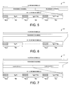
- FIG. 5 illustrates a first embodiment of a unified synchronous ranging channel 51 .
- FIG. 6 illustrates a second embodiment of a unified synchronous ranging channel 61 .
- FIG. 7 illustrates a third embodiment of a unified synchronous ranging channel 71 .
- ranging channel 71 spans over six OFDM symbols, only one ranging channel may be allocated within a six-symbol long subframe. As compared to ranging channel 61 of FIG. 6 , although a relatively shorter code sequence is used, longer cell coverage is provided because better code detection can still be achieved via time-domain repetition and channel diversity gain.
- FIG. 8 illustrates a fourth embodiment of a unified synchronous ranging channel 81 .
- ranging channel 81 is further TDM with a five-symbol or six-symbol long data channel within a six-symbol long or seven-symbol long subframe.
- FIG. 9 illustrates a fifth embodiment of a unified synchronous ranging channel 91 .
- ranging channel 91 looks similar to ranging channel 51 of FIG. 5 , the underline physical structures of ranging channels 51 and 91 are different.
- each cell utilizes all ranging opportunities allocated in one subframe, but different cells use different code sets for periodic ranging over the same synchronous ranging allocation.
- one cell utilizes only a portion of the ranging opportunities for periodic ranging, and the rest of the ranging opportunities are utilized by other cells.
- ranging channel 91 is further CDM and/or TDM among different cells in a scheduling interval for transmission.
- FIG. 10 illustrates a signaling scheme to distinguish the different configuration modes of a synchronous ranging channel.
- K2 K1xQ
- One bit in Super Frame Header (SFH) is broadcasted via a broadcast channel to signal different configuration modes of the ranging channel. If the bit is set to one, then each cell utilizes all ranging opportunities (i.e., all K2 OFDM symbols) for ranging.
- the ranging channel is FDM with data channels and CDM among cells. If the bit is set to zero, then cells with cell ID matching equation (1)(see Eq. (1) below) utilize OFDM symbols (qxK1+1) ⁇ (qxK1+K1) for ranging.
- both ranging code and ranging message may be transmitted together in the same ranging channel structure.
- FIG. 11 illustrates a physical structure of a synchronous ranging channel 110 that is used to transmit both a ranging code and a ranging message.
- the ranging code is mapped onto subcarriers denoted with white blocks, while the ranging message is mapped onto subcarriers denoted with shaded blocks.
- the ranging message may include information such as the mobile station ID in the femtocell and the bandwidth requirement for the next RNG_REQ to be transmitted by the mobile station.
- transmitting a ranging code together with a ranging message may help to reduce access latency and handover interruption time.
- FIG. 12 illustrates a first example of an initial ranging procedure when both ranging code and ranging message for bandwidth request are transmitted in the same synchronous ranging channel.
- a mobile station first transmits an initial ranging code and a ranging message for bandwidth request via a synchronous ranging channel to a femto base station.
- the ranging message comprises the mobile station ID and a ranging request (RNG-REQ) size.
- the femto base station sends an acknowledgement of the initial ranging back to the mobile station.
- the femto base station After correctly decoding the ranging message, the femto base station also sends an UL grant with the requested RNG-REQ size to the mobile station.
- the mobile station After receiving the UL grant, the mobile station transmits a RNG-REQ and receives a RNG-RSP back from the femto base station. Because the ranging message for bandwidth request is sent together with the ranging code without using extra steps, the overall access latency is reduced.
- FIG. 13 illustrates a second example of an initial ranging procedure when both ranging code and ranging message for bandwidth request are transmitted in the same synchronous ranging channel. Similar to the ranging procedure in FIG. 12 , a ranging code together with a ranging message for bandwidth request is transmitted by a mobile station to a femto base station via a synchronous ranging channel. In the example of FIG. 13 , however, the ranging message is not correctly decoded by the femto base station. The procedure falls back to conventional initial ranging procedure. As a result, the femto base station has to figure out the requested RNG-REQ size when sending an UL grant to the mobile station. If the granted RNG-REQ size is too small, then the mobile station has to restart the initial ranging and the overall access latency is increased. Under proper ranging channel allocation, the probability for fallback mode would be very low.
- the proposed unified synchronous ranging channel may be used for different ranging procedures including initial ranging, handover ranging, and periodic ranging in femtocell environment, it is used only for periodic ranging in macrocell environment.
- Different ranging procedures have different performance requirements defined under the IEEE 802.16m SRD.
- the idle-to-active latency requirement is 100 mille seconds.
- the HO interruption time requirement of intra-frequency HO is 27.5 mille seconds, and the HO interruption time requirement of inter-frequency HO is 40 mille seconds within the same spectrum band and 60 mille seconds between different spectrum bands.
- the unified synchronous ranging channel needs to be allocated more frequent in femtocells than in macrocells in order to meet the stricter HO interruption time requirement for handover procedure. Shorter allocation periodicity of the ranging channel, however, will increase the overall spectrum overhead in femtocells.
- Different embodiments and examples of ranging channel allocation schemes are now described below with more details.
- FIG. 14 illustrates a separate ranging channel allocation scheme for macrocells and femtocells.
- macrocells and femtocells allocate their own ranging channels separately.
- one ranging channel is allocated in every ten superframes (i.e., 200 ms) for periodic ranging (PR).
- PR periodic ranging
- IR initial ranging
- HR handover ranging
- PR periodic ranging
- FIG. 15 illustrates a collocated ranging channel allocation scheme for macrocells and femtocells.
- both macrocells and femtocells allocate one ranging channel every one superframe. Because all ranging channels are shared among macrocells and femtocells, such collocated ranging channel allocation scheme may result in higher contention.
- FIG. 16 illustrates a hybrid ranging channel allocation scheme for macrocells and femtocells.
- femtocells allocate ranging channels more frequent (i.e., one ranging channel in every 20 ms) than macrocells (i.e., one ranging channel in every 200 ms).
- macrocells and femtocells negotiate with each other such that ranging channels allocated by macrocells overlap with part of the ranging channels allocated by femtocells. Because some allocations are shared by macrocells and femtocells and other allocations are for femtocells only, such hybrid ranging channel allocation scheme is able to provide better contention control with less overhead.
- FIG. 17A illustrates a frequency-domain representation of a ranging preamble code X P that is mapped onto a unified synchronous ranging channel 171 .
- the ranging channel comprises a radio resource region that spans over 72 subcarriers and 3 OFDM symbols. As illustrated in FIG. 17A , each X P (k) (i.e., may be either a binary value or a complex value) is allocated into a corresponding subcarrier and OFDM symbol within the radio resource region of the ranging channel.
- FIG. 17A illustrates a frequency-domain representation of a ranging preamble code X P that is mapped onto a unified synchronous ranging channel 171 .
- the ranging preamble code X P comprises a long code sequence X P (k), where
- FIG. 17B illustrates a frequency-domain representation of the same ranging preamble code X P that is mapped onto a unified synchronous ranging channel 172 with time-domain repetition. Similar to FIG. 17A , ranging code sequence X P (k) is allocated into a 72 ⁇ 3 resource region of the ranging channel. The same long ranging code sequence X P (k) is then repeated in time domain.
- FIG. 17C illustrates a time-domain representation of the ranging preamble code X P that is mapped onto unified ranging channel 172 in FIG. 17B .
- the long ranging preamble code X P is partitioned into three portions (i.e., X P (k), X P (k+N 3 ), and X P (k+2N 3 )) and allocated to each of the three OFDM symbols. More specifically, X P (k) represents a first code segment of code sequence “X P (0) . . . X P (71)”, X P (k+N 3 ) represents a second code segment of code sequence “X P (71) . . .
- a Zadoff-Chu sequence is a complex-valued mathematical sequence that gives rise to an electromagnetic signal of constant amplitude when applied to radio signals.
- a generated Zadoff-Chu sequence that has not been shifted is known as a “root sequence.”
- time-domain cyclic Zadoff-Chu code sequences are typically generated by time-domain cyclic shifting a Zadoff-Chu root sequence.
- a cyclic-shifted version of a Zadoff-Chu sequence does not cross-correlate with each other when the radio signals are recovered at the receiver side.
- code sequences generated by time-domain cyclic shifting based on the same root sequence are orthogonal to each other.
- code-based time-domain cyclic-shifted versions of a Zadoff-Chu sequence may be generated by the following equation (2):
- p is the ranging code index
- r p is the root index of the Zadoff-Chu sequence
- N 1 is the code length of the Zadoff-Chu sequence
- N 2 is the ranging preamble length
- Ncs is the number of cyclic-shift samples applied for the generation of cyclic ranging codes
- s p is the number of multiple Ncs applied to generate cyclic ranging code with index p.
- FIG. 18 illustrates a time-domain representation of a Zadoff-Chu root sequence and a time-domain cyclic-shifted code sequence under Equation (2).
- cyclic code sequences are generated by applying time domain cyclic shift of (2*k*s p *N CS ) to a Zadoff-Chu root sequence.
- the top portion represents a Zadoff-Chu root sequence and the bottom portion represents a cyclic-shifted Zadoff-Chu sequence.
- ranging code segment#1“0, 1, 2, 3, 4, 5, 6” represents the time-domain sample values of the first code segment (i.e., X P (k)) in frequency domain.
- ranging code segment#2“7, 8, 9, 10, 11, 12, 13” represents the time-domain sample values of the second code segment (i.e., X P (k+N 3 )) in frequency domain.
- ranging code segment#3“14, 15, 16, 17, 18, 19, 20” represents the time-domain sample values of the third code segment (i.e., X P (k+2N 3 )) in frequency domain. Because the number of samples to be shifted for each code segment is based on the value of index k, each code segment in a different OFDM symbol is cyclic shifted by a different number of samples. In the example of FIG.
- code segment#1 is shifted by one sample to become “6, 0, 1, 2, 3, 4, 5”
- code segment#2 is shifted by two samples to become “12, 13, 7, 8, 9, 10, 11”
- code segment#3 is shifted by three samples to become “18, 19, 20, 14, 15, 16, 17”.
- the code-based time-domain cyclic shift scheme introduces more detection complexity for a decoder because it requires frequency domain correlation between all possible cyclic code sequences at the receiver side to identify which cyclic code sequence is transmitted.
- symbol-based time-domain cyclic code sequences of a Zadoff-Chu root sequence may be generated by the following equations (3) or (4):
- N 1 is the code length of the Zadoff-Chu sequence
- N 2 is the ranging preamble length
- N 3 is the applied code segment length in the frequency domain
- Ncs is the number of cyclic-shift samples applied for the generation of cyclic ranging codes
- s p is the number of multiple Ncs applied to generate cyclic ranging code with index p.
- n is the OFDM symbol index
- N FFT is the FFT size
- the rest of the terms have the same meaning as the terms in Equation (2).
- Equation (3) and (4) are different in forms, the generated cyclic-shifted code sequences X P (k) and X P (n,k) are the same in substance.
- FIG. 19 illustrates a time-domain representation of a Zadoff-Chu root sequence and a time-domain cyclic-shifted code sequence under Equation (3).
- cyclic code sequences are generated by applying time domain cyclic shift of (2*mod(k,N 3 )*s p *N CS ) to a Zadoff-Chu root sequence.
- the number of samples to be shifted for each code segment is thus based on the value of mod(k,N 3 ), which is the subcarrier index (i.e., 0 to 71) that is reset to zero for every OFDM symbol.
- mod(k,N 3 ) which is the subcarrier index (i.e., 0 to 71) that is reset to zero for every OFDM symbol.
- each code segment in a different OFDM symbol is cyclic shifted by the same number of samples.
- mod(k,N 3 ) is the subcarrier index (i.e., 0 to 71) that is reset to zero for every OFDM symbol
- the top portion represents different code segments of a Zadoff-Chu root sequence and the bottom portion represents different code segments of a cyclic-shifted Zadoff-Chu sequence.
- each code segment in an OFDM symbol is shifted by a fixed number of two samples in time domain. Therefore, the symbol-based time-domain cyclic shift scheme reduces detection complexity for a decoder because it requires frequency domain correlation between only root sequences at the receiver side to identify which code sequence is transmitted.
- mobile station MS 41 may perform initial ranging or periodic ranging with its potential serving base station BS 31 .
- MS 41 may also perform handover ranging with a target base station.
- mobile station MS 41 generates a ranging code (i.e., a cyclic Zadoff-Chu sequence X P ) and transmits the ranging code to femto base station BS 31 via unified synchronous ranging channel 40 .
- BS 31 receives the initial ranging code and then detects which ranging code is transmitted from MS 41 and estimates the uplink timing offset between MS 41 and BS 31 by the received ranging code so that the uplink synchronization between MS 41 and BS 31 can be achieved.
- FIG. 20 illustrates a first embodiment of a decoder 201 of a base station in accordance with one novel aspect.
- a ranging code sequence X P and other data that are transmitted via K OFDM symbols in time domain.
- Decoder 201 comprises a number of (i.e., K) FFT module 202 , extractor 203 , correlator 204 , zero padder 205 , IFFT module 206 , a summation module 207 , a modified peak test module 208 , and a detection module 209 .
- K a number of FFT module 202 , extractor 203 , correlator 204 , zero padder 205 , IFFT module 206 , a summation module 207 , a modified peak test module 208 , and a detection module 209 .
- Each code sequence part is transferred from time domain to frequency domain by a corresponding FFT module and extracted from other data by a corresponding extractor.
- Each extracted code sequence part is then correlated to a corresponding code part of all possible code sequences (i.e., all Zadoff-Chu root sequences) by a corresponding correlator.
- the first extracted code sequence is correlated to CODE P part #1, and the K th extracted code sequence is correlated to CODE P part #K, where CODE P is a root sequence with code index P.
- each correlated code sequence part is then transferred back to time domain values by a corresponding IFFT module.
- the time-domain values of the code sequence parts are then added up one-by-one on the corresponding index for each code index P by summation module 207 to form a likelihood vector.
- the peak value of the likelihood vector represents a likelihood value t p of a possible code sequence CODE P .
- the peak values are then normalized by modified peak test module 208 . If a normalized peak value of code index P is larger than a corresponding threshold value, then CODE P is obtained by detection module 209 . If the ranging code sequence X P is a symbol-based time-domain cyclic Zadoff-Chu sequence based on root sequence CODE P as described above with respect to FIG. 19 , then a timing location of the peak value is also detected by detection module 209 .
- decoder 201 is able to identify the exact cyclic-shifted ranging code sequence X P based on the root sequence CODE P transmitted by the mobile station.
- the uplink timing offset between mobile station and base station is estimated such that UL synchronization can be achieved based on the estimated timing offset.
- each peak value t p is normalized by modified peak test module 208 .
- the threshold value of a code index p may vary based on a particular SNR value in a particular system environment.
- the same threshold value can be used for a code index P.
- the peak values may be normalized by using the following equation (5):
- FIG. 21 illustrates a second embodiment of a decoder 211 of a base station in accordance with one novel aspect. Decoder 211 is similar to decoder 201 of FIG. 20 . In the example of FIG. 21 , however, the summation module is placed before the IFFT module such that only one IFFT module is required in decoder 211 .
- FIG. 22 illustrates a third embodiment of a decoder 221 of a base station in accordance with one novel aspect.
- the ranging code sequence X P is repeated in time domain for Q times.
- Each repeated ranging code sequence X P is independently decoded by decoder 221 as by decoder 201 of FIG. 20 .
- a number of (i.e. Q) likelihood vectors of each X P repetition for each code index P is outputted by a corresponding summation module, the Q likelihood vectors of all X P repetitions are then added one-by-one on the corresponding index again by a likelihood-combining module 228 for each code index P.
- the likelihood-combining module 228 thus outputs a final likelihood vector of the ranging code sequence X P for a particular code index P.
- the peak value of each final likelihood vector is then normalized by peak test module 229 .
- detection module 230 identifies the actual code index of the transmitted ranging code and estimates the timing offset for uplink synchronization.
- FIG. 23 illustrates a fourth embodiment of a decoder 231 of a base station in accordance with one novel aspect.
- the ranging code sequence X P is also repeated in time domain for Q times.
- Decoder 231 is similar to decoder 221 of FIG. 22 .
- the summation module is placed before the IFFT module such that only one IFFT module is required in decoder 231 for each repetition of ranging code sequence X P .
- femto base station is referred to Home eNB (HeNB).
- HeNB Home eNB
- RACH random access channel
Landscapes
- Engineering & Computer Science (AREA)
- Signal Processing (AREA)
- Computer Networks & Wireless Communication (AREA)
- Mobile Radio Communication Systems (AREA)
Abstract
Description
cell ID mod p=q Eq. (1)
where p is the ranging code index, rp is the root index of the Zadoff-Chu sequence, N1 is the code length of the Zadoff-Chu sequence, N2 is the ranging preamble length, Ncs is the number of cyclic-shift samples applied for the generation of cyclic ranging codes, and sp is the number of multiple Ncs applied to generate cyclic ranging code with index p.
where p is the ranging code index, rp is the root index of the Zadoff-Chu sequence, N1 is the code length of the Zadoff-Chu sequence, N2 is the ranging preamble length, N3 is the applied code segment length in the frequency domain, Ncs is the number of cyclic-shift samples applied for the generation of cyclic ranging codes, and sp is the number of multiple Ncs applied to generate cyclic ranging code with index p.
where n is the OFDM symbol index, NFFT is the FFT size, and the rest of the terms have the same meaning as the terms in Equation (2). Although Equation (3) and (4) are different in forms, the generated cyclic-shifted code sequences XP(k) and XP(n,k) are the same in substance.
Pr (Normalization {tp}>T| there is no code sequence transmitted)<=PFA, where Nc is the number of code sequences, m is the maximal possible transmitted code sequences, and p is the code index.
Claims (21)
Priority Applications (6)
| Application Number | Priority Date | Filing Date | Title |
|---|---|---|---|
| EP09831481.8A EP2308207B1 (en) | 2008-12-12 | 2009-12-11 | Unified synchronous ranging channel design and allocation in wireless ofdma systems |
| TW098142444A TWI404438B (en) | 2008-12-12 | 2009-12-11 | Method of uplink synchronization a cellular ofdma system,ofdm system,base station and mobile station |
| PCT/CN2009/075512 WO2010066204A1 (en) | 2008-12-12 | 2009-12-11 | Unified synchronous ranging channel design and allocation in wireless ofdma systems |
| JP2010550022A JP2011515055A (en) | 2008-12-12 | 2009-12-11 | Unified Synchronous Ranging Channel Design and Assignment in Wireless OFDMA System |
| CN2009801008313A CN101843069B (en) | 2008-12-12 | 2009-12-11 | Uplink synchronization method, cellular OFDMA system and base station |
| US12/653,360 US8345623B2 (en) | 2008-12-12 | 2009-12-11 | Unified synchronous ranging channel design and allocation in wireless OFDMA systems |
Applications Claiming Priority (6)
| Application Number | Priority Date | Filing Date | Title |
|---|---|---|---|
| US12191608P | 2008-12-12 | 2008-12-12 | |
| US21811209P | 2009-06-18 | 2009-06-18 | |
| US23353309P | 2009-08-13 | 2009-08-13 | |
| US23620109P | 2009-08-24 | 2009-08-24 | |
| US24359509P | 2009-09-18 | 2009-09-18 | |
| US12/653,360 US8345623B2 (en) | 2008-12-12 | 2009-12-11 | Unified synchronous ranging channel design and allocation in wireless OFDMA systems |
Publications (2)
| Publication Number | Publication Date |
|---|---|
| US20100150100A1 US20100150100A1 (en) | 2010-06-17 |
| US8345623B2 true US8345623B2 (en) | 2013-01-01 |
Family
ID=42240423
Family Applications (2)
| Application Number | Title | Priority Date | Filing Date |
|---|---|---|---|
| US12/653,336 Active 2031-03-12 US8345659B2 (en) | 2008-12-12 | 2009-12-11 | Unified synchronous ranging channel structure and ranging code generation and detection in wireless OFDMA systems |
| US12/653,360 Active 2031-03-07 US8345623B2 (en) | 2008-12-12 | 2009-12-11 | Unified synchronous ranging channel design and allocation in wireless OFDMA systems |
Family Applications Before (1)
| Application Number | Title | Priority Date | Filing Date |
|---|---|---|---|
| US12/653,336 Active 2031-03-12 US8345659B2 (en) | 2008-12-12 | 2009-12-11 | Unified synchronous ranging channel structure and ranging code generation and detection in wireless OFDMA systems |
Country Status (1)
| Country | Link |
|---|---|
| US (2) | US8345659B2 (en) |
Families Citing this family (20)
| Publication number | Priority date | Publication date | Assignee | Title |
|---|---|---|---|---|
| KR20090006708A (en) | 2007-07-12 | 2009-01-15 | 엘지전자 주식회사 | Method for transmitting scheduling request signal |
| KR101668704B1 (en) * | 2008-09-05 | 2016-10-28 | 엘지전자 주식회사 | Downlink silent period for positioning |
| KR101666894B1 (en) * | 2009-01-05 | 2016-10-17 | 엘지전자 주식회사 | Method for transmitting raning information in mobile communications system and terminal thereof |
| KR101598910B1 (en) * | 2009-01-07 | 2016-03-02 | 엘지전자 주식회사 | A method and device for transmitting and receiving a signal using a time division duplexing frame structure in a wireless communication system |
| WO2010142312A1 (en) * | 2009-06-12 | 2010-12-16 | Telefonaktiebolaget L M Ericsson (Publ) | Monitoring of delay in packet-switched networks |
| US8005060B2 (en) * | 2009-06-23 | 2011-08-23 | Cisco Technology, Inc. | Beamforming techniques to improve ranging signal detection |
| KR20110003285A (en) * | 2009-07-03 | 2011-01-11 | 엘지전자 주식회사 | Ranging by mobile station in legacy support mode |
| IN2013CN00519A (en) * | 2009-07-06 | 2015-07-03 | Apple Inc | |
| US8576789B2 (en) * | 2009-08-28 | 2013-11-05 | Lg Electronics Inc. | Method and apparatus for allocating ranging channel for synchronized mobile station in wireless communication system |
| KR101667588B1 (en) * | 2009-10-21 | 2016-10-19 | 엘지전자 주식회사 | Method for mapping Ranging Channels and Opportunities in a Broadband Wireless Access System |
| US9019811B2 (en) * | 2009-11-05 | 2015-04-28 | Lg Electronics Inc. | Method and apparatus for generating ranging preamble code in wireless communication system |
| US9204404B2 (en) * | 2010-02-11 | 2015-12-01 | Lg Electronics Inc. | Device for controlling uplink transmission power and a method for the same |
| US8472399B2 (en) | 2010-07-06 | 2013-06-25 | Apple Inc. | Ranging channel structures and methods |
| US9148858B2 (en) * | 2010-07-12 | 2015-09-29 | Samsung Electronics Co., Ltd. | Apparatus and method for controlling uplink transmission power in a mobile communication system |
| KR20120086781A (en) * | 2011-01-27 | 2012-08-06 | 삼성전자주식회사 | Method and apparatus for reporting location of mobile station in wireless communication system |
| CN102625460B (en) * | 2011-01-31 | 2015-03-18 | 北京三星通信技术研究有限公司 | Network access method |
| KR20120090447A (en) * | 2011-02-08 | 2012-08-17 | 삼성전자주식회사 | Method and apparatus for allocating ranging codes in a communication system |
| US9438310B2 (en) * | 2012-02-29 | 2016-09-06 | Texas Instruments Incorporated | Multi-length cyclic prefix for OFDM transmission in PLC channels |
| KR101640566B1 (en) * | 2012-12-11 | 2016-07-18 | 한국전자통신연구원 | Ranging signal generating apparatus for wireless communication system and ranging signal generating method for a wireless terminal |
| CN111386740B (en) * | 2017-11-08 | 2023-04-11 | Lg电子株式会社 | Distance measuring method of user equipment in wireless communication system and user equipment using the same |
Citations (13)
| Publication number | Priority date | Publication date | Assignee | Title |
|---|---|---|---|---|
| US20020159422A1 (en) * | 2001-03-09 | 2002-10-31 | Xiaodong Li | Communication system using OFDM for one direction and DSSS for another direction |
| US20050195791A1 (en) | 2004-03-05 | 2005-09-08 | Samsung Electronics Co., Ltd. | Apparatus and method for assigning a ranging channel and transmitting and receiving a ranging signal in an OFDM system |
| US20060098749A1 (en) | 2004-10-12 | 2006-05-11 | Samsung Electronics Co., Ltd. | Apparatus and method for detecting ranging signal in an orthogonal frequency division multiple access mobile communication system |
| CN101217818A (en) | 2008-01-03 | 2008-07-09 | 北京北方烽火科技有限公司 | A ranging code detecting method of base station receiver |
| WO2008130165A1 (en) | 2007-04-19 | 2008-10-30 | Electronics And Telecommunications Research Institute | Method and apparatus of generating signals for initial ranging in ofdma system |
| US20080267303A1 (en) * | 2007-04-30 | 2008-10-30 | Telefonaktiebolaget L M Ericsson (Publ) | Synchronization for Chirp Sequences |
| US20090168662A1 (en) | 2006-02-10 | 2009-07-02 | Sharp Kabushiki Kaisha | Mobile communication system, mobile station device, base station device, and mobile communication method |
| US20100135360A1 (en) | 2007-04-26 | 2010-06-03 | Lg Electronics Inc. | Method of transmitting reference signal in wireless communication system |
| US20110002288A1 (en) | 2009-07-02 | 2011-01-06 | Lg Electronics Inc. | Method and apparatus for allocating ranging channel in wireless communication system |
| US8098713B2 (en) * | 2007-04-13 | 2012-01-17 | General Dynamics C4 Systems | Methods and apparatus for generating and communicating wireless signals having pilot signals with variable pilot signal parameters |
| US8107428B2 (en) * | 2007-12-06 | 2012-01-31 | Ntt Docomo, Inc. | Method of ranging signal design and transmission for MIMO-OFDMA initial ranging process |
| US20120039272A1 (en) * | 2010-08-13 | 2012-02-16 | Lg Electronics Inc. | Method and user equipment for transmitting ranging signal, and method and base station for receiving ranging signal |
| US20120052899A1 (en) | 2010-08-30 | 2012-03-01 | Xiaoqiu Wang | Wireless Communication System, Base Station Device, and Program |
-
2009
- 2009-12-11 US US12/653,336 patent/US8345659B2/en active Active
- 2009-12-11 US US12/653,360 patent/US8345623B2/en active Active
Patent Citations (13)
| Publication number | Priority date | Publication date | Assignee | Title |
|---|---|---|---|---|
| US20020159422A1 (en) * | 2001-03-09 | 2002-10-31 | Xiaodong Li | Communication system using OFDM for one direction and DSSS for another direction |
| US20050195791A1 (en) | 2004-03-05 | 2005-09-08 | Samsung Electronics Co., Ltd. | Apparatus and method for assigning a ranging channel and transmitting and receiving a ranging signal in an OFDM system |
| US20060098749A1 (en) | 2004-10-12 | 2006-05-11 | Samsung Electronics Co., Ltd. | Apparatus and method for detecting ranging signal in an orthogonal frequency division multiple access mobile communication system |
| US20090168662A1 (en) | 2006-02-10 | 2009-07-02 | Sharp Kabushiki Kaisha | Mobile communication system, mobile station device, base station device, and mobile communication method |
| US8098713B2 (en) * | 2007-04-13 | 2012-01-17 | General Dynamics C4 Systems | Methods and apparatus for generating and communicating wireless signals having pilot signals with variable pilot signal parameters |
| WO2008130165A1 (en) | 2007-04-19 | 2008-10-30 | Electronics And Telecommunications Research Institute | Method and apparatus of generating signals for initial ranging in ofdma system |
| US20100135360A1 (en) | 2007-04-26 | 2010-06-03 | Lg Electronics Inc. | Method of transmitting reference signal in wireless communication system |
| US20080267303A1 (en) * | 2007-04-30 | 2008-10-30 | Telefonaktiebolaget L M Ericsson (Publ) | Synchronization for Chirp Sequences |
| US8107428B2 (en) * | 2007-12-06 | 2012-01-31 | Ntt Docomo, Inc. | Method of ranging signal design and transmission for MIMO-OFDMA initial ranging process |
| CN101217818A (en) | 2008-01-03 | 2008-07-09 | 北京北方烽火科技有限公司 | A ranging code detecting method of base station receiver |
| US20110002288A1 (en) | 2009-07-02 | 2011-01-06 | Lg Electronics Inc. | Method and apparatus for allocating ranging channel in wireless communication system |
| US20120039272A1 (en) * | 2010-08-13 | 2012-02-16 | Lg Electronics Inc. | Method and user equipment for transmitting ranging signal, and method and base station for receiving ranging signal |
| US20120052899A1 (en) | 2010-08-30 | 2012-03-01 | Xiaoqiu Wang | Wireless Communication System, Base Station Device, and Program |
Non-Patent Citations (2)
| Title |
|---|
| International Search Report and Written Opinion of International Search Authority for PCT/CN2009/075512 dated Mar. 18, 2010 (10 pages). |
| Office Action, for U.S. Appl. No. 12/653,336, dated on Apr. 25, 2012 (10 pages). |
Also Published As
| Publication number | Publication date |
|---|---|
| US20100150100A1 (en) | 2010-06-17 |
| US20100150099A1 (en) | 2010-06-17 |
| US8345659B2 (en) | 2013-01-01 |
Similar Documents
| Publication | Publication Date | Title |
|---|---|---|
| US8345623B2 (en) | Unified synchronous ranging channel design and allocation in wireless OFDMA systems | |
| US10873957B2 (en) | Method and apparatus for transmitting adaptive partial subframe in unlicensed frequency band, method and apparatus for identifying a frame structure, and method and apparatus for transmitting signal | |
| US11115943B2 (en) | Method of transmitting and receiving synchronization signal block and method therefor | |
| US10609660B2 (en) | Synchronization for wideband coverage enhancement | |
| US10484954B2 (en) | Synchronization for wideband coverage enhancement | |
| US8576786B2 (en) | Synchronization channel for advanced wireless OFDM/OFDMA systems | |
| EP2911321B1 (en) | Method for configuring wireless frame of user equipment, user equipment, method for configuring wireless frame of base station, and base station | |
| US20170325260A1 (en) | Method and apparatus for initial access in wireless communication systems | |
| US7539263B2 (en) | Method for transmitting and receiving preamble sequences in an orthogonal frequency division multiplexing communication system using a multiple input multiple output scheme | |
| US11855819B2 (en) | Waveform multiplexing in millimeter wave band | |
| US20110171949A1 (en) | Two-step uplink synchronization for pico/femtocell | |
| TW201134150A (en) | Frame structure for support of large delay spread deployment scenarios | |
| EP2308207B1 (en) | Unified synchronous ranging channel design and allocation in wireless ofdma systems | |
| KR20050089709A (en) | Apparatus of transmitting/receiving raging signal in a orthogonal frequency division multiple system and the method thereof | |
| JPWO2018123468A1 (en) | Base station apparatus, terminal apparatus, communication method, and integrated circuit | |
| KR20100073752A (en) | Method and apparatus for allocation of frequency in wireless communication systems with frequency hopping mode | |
| EP2412137B1 (en) | Low latency synchronization scheme for wireless ofdma systems | |
| US11659505B2 (en) | Method and system for synchronization of small cell | |
| US11683816B1 (en) | Systems and methods for fast control messaging for multiple numerology access zones | |
| Pisal | Physical Layer Comparative Study of WiMAX and LTE |
Legal Events
| Date | Code | Title | Description |
|---|---|---|---|
| AS | Assignment |
Owner name: MEDIATEK INC.,TAIWAN Free format text: ASSIGNMENT OF ASSIGNORS INTEREST;ASSIGNORS:CHEN, YIH-SHEN;LIAO, PEI-KAI;REEL/FRAME:023703/0202 Effective date: 20091210 Owner name: MEDIATEK INC., TAIWAN Free format text: ASSIGNMENT OF ASSIGNORS INTEREST;ASSIGNORS:CHEN, YIH-SHEN;LIAO, PEI-KAI;REEL/FRAME:023703/0202 Effective date: 20091210 |
|
| STCF | Information on status: patent grant |
Free format text: PATENTED CASE |
|
| FPAY | Fee payment |
Year of fee payment: 4 |
|
| AS | Assignment |
Owner name: HFI INNOVATION INC., TAIWAN Free format text: ASSIGNMENT OF ASSIGNORS INTEREST;ASSIGNOR:MEDIATEK INC.;REEL/FRAME:047068/0617 Effective date: 20180630 |
|
| MAFP | Maintenance fee payment |
Free format text: PAYMENT OF MAINTENANCE FEE, 8TH YEAR, LARGE ENTITY (ORIGINAL EVENT CODE: M1552); ENTITY STATUS OF PATENT OWNER: LARGE ENTITY Year of fee payment: 8 |