US8334034B2 - Rapid release and anti-drip porous reservoirs - Google Patents
Rapid release and anti-drip porous reservoirs Download PDFInfo
- Publication number
- US8334034B2 US8334034B2 US11/857,788 US85778807A US8334034B2 US 8334034 B2 US8334034 B2 US 8334034B2 US 85778807 A US85778807 A US 85778807A US 8334034 B2 US8334034 B2 US 8334034B2
- Authority
- US
- United States
- Prior art keywords
- reservoir
- lateral
- porous
- porous body
- fluid
- Prior art date
- Legal status (The legal status is an assumption and is not a legal conclusion. Google has not performed a legal analysis and makes no representation as to the accuracy of the status listed.)
- Expired - Fee Related, expires
Links
Images


Classifications
-
- B—PERFORMING OPERATIONS; TRANSPORTING
- B01—PHYSICAL OR CHEMICAL PROCESSES OR APPARATUS IN GENERAL
- B01F—MIXING, e.g. DISSOLVING, EMULSIFYING OR DISPERSING
- B01F33/00—Other mixers; Mixing plants; Combinations of mixers
- B01F33/35—Mixing after turning the mixing vessel upside down
-
- B—PERFORMING OPERATIONS; TRANSPORTING
- B01—PHYSICAL OR CHEMICAL PROCESSES OR APPARATUS IN GENERAL
- B01F—MIXING, e.g. DISSOLVING, EMULSIFYING OR DISPERSING
- B01F33/00—Other mixers; Mixing plants; Combinations of mixers
- B01F33/50—Movable or transportable mixing devices or plants
- B01F33/501—Movable mixing devices, i.e. readily shifted or displaced from one place to another, e.g. portable during use
- B01F33/5011—Movable mixing devices, i.e. readily shifted or displaced from one place to another, e.g. portable during use portable during use, e.g. hand-held
-
- B—PERFORMING OPERATIONS; TRANSPORTING
- B01—PHYSICAL OR CHEMICAL PROCESSES OR APPARATUS IN GENERAL
- B01F—MIXING, e.g. DISSOLVING, EMULSIFYING OR DISPERSING
- B01F35/00—Accessories for mixers; Auxiliary operations or auxiliary devices; Parts or details of general application
- B01F35/30—Driving arrangements; Transmissions; Couplings; Brakes
- B01F35/32—Driving arrangements
- B01F35/32005—Type of drive
- B01F35/3202—Hand driven
- B01F35/32021—Shaking by hand a portable receptacle or stirrer for mixing
-
- B—PERFORMING OPERATIONS; TRANSPORTING
- B01—PHYSICAL OR CHEMICAL PROCESSES OR APPARATUS IN GENERAL
- B01F—MIXING, e.g. DISSOLVING, EMULSIFYING OR DISPERSING
- B01F35/00—Accessories for mixers; Auxiliary operations or auxiliary devices; Parts or details of general application
- B01F35/50—Mixing receptacles
- B01F35/53—Mixing receptacles characterised by the configuration of the interior, e.g. baffles for facilitating the mixing of components
- B01F35/531—Mixing receptacles characterised by the configuration of the interior, e.g. baffles for facilitating the mixing of components with baffles, plates or bars on the wall or the bottom
-
- B—PERFORMING OPERATIONS; TRANSPORTING
- B01—PHYSICAL OR CHEMICAL PROCESSES OR APPARATUS IN GENERAL
- B01F—MIXING, e.g. DISSOLVING, EMULSIFYING OR DISPERSING
- B01F35/00—Accessories for mixers; Auxiliary operations or auxiliary devices; Parts or details of general application
- B01F35/30—Driving arrangements; Transmissions; Couplings; Brakes
- B01F35/32—Driving arrangements
- B01F35/32005—Type of drive
- B01F35/3202—Hand driven
-
- Y—GENERAL TAGGING OF NEW TECHNOLOGICAL DEVELOPMENTS; GENERAL TAGGING OF CROSS-SECTIONAL TECHNOLOGIES SPANNING OVER SEVERAL SECTIONS OF THE IPC; TECHNICAL SUBJECTS COVERED BY FORMER USPC CROSS-REFERENCE ART COLLECTIONS [XRACs] AND DIGESTS
- Y10—TECHNICAL SUBJECTS COVERED BY FORMER USPC
- Y10T—TECHNICAL SUBJECTS COVERED BY FORMER US CLASSIFICATION
- Y10T428/00—Stock material or miscellaneous articles
- Y10T428/13—Hollow or container type article [e.g., tube, vase, etc.]
- Y10T428/1352—Polymer or resin containing [i.e., natural or synthetic]
- Y10T428/1376—Foam or porous material containing
Definitions
- the invention relates generally to porous reservoirs, and, more particularly, to an improved porous reservoir with an enhanced ability to retain a relatively large volume of a fluid or solid and release the fluid or solid into another environment. Even more specifically, this invention relates to three dimensional, self-sustaining, porous reservoirs.
- Porous reservoirs formed from foam, cloth, non-woven fabrics, paper, sponges, bundled and/or bonded or unbonded natural or man-made fibers, porous metal or plastics, porous ceramic, cotton, linen, and similar fiber-based parts, pumice, asbestos, vermiculite, fused sand and fiber glass may absorb and/or hold various liquid or solid materials.
- such “loaded materials” may be held in a porous article until the porous article is placed into a liquid that is miscible with the loaded material, whereupon the loaded material is released into and/or dissolved by the liquid.
- An exemplary application is one in which a porous reservoir is loaded with a concentrated cleaning fluid.
- the porous reservoir may be sized for insertion into a container of water or other liquid for release and dissolution of the cleaning fluid into the water.
- porous reservoirs generally exhibit a tradeoff between the volume of material that can be held in the porous reservoir (referred to herein as the material “transport volume”) and the rate at which the loaded fluid or solid material may be removed from the reservoir and dispersed or dissolved into the miscible fluid (the “dissolution rate”).
- transport volume the volume of material that can be held in the porous reservoir
- dissolution rate the rate at which the loaded fluid or solid material may be removed from the reservoir and dispersed or dissolved into the miscible fluid
- reservoirs having a high transport volume generally have low dissolution rates.
- reservoirs with large areas of exposed surface so as to produce high dissolution rates generally have comparatively low transport volumes and or exhibit leakage problems.
- the present invention provides reservoirs having a high transport volume and a high dissolution rate.
- a particular aspect of the invention provides a fluid reservoir for retaining a particular fluid against an environmental force directed in a force direction.
- the fluid reservoir comprises a three dimensional porous body that has a plurality of reservoir capillaries formed therein and has a transport volume and effective capillarity in the force direction for the particular fluid when the porous body is oriented in a predetermined orientation.
- the fluid reservoir also comprises at least one lateral indentation in a surface of the porous body. Each of the at least one lateral indentation defines opposing reservoir surfaces each having a lateral surface component orthogonal to the force direction.
- the at least one lateral indentation is configured so that at least a majority of the reservoir capillaries have a force-aligned length component that is less than the effective capillarity for the particular fluid.
- the three dimensional porous reservoir initially has a plurality of reservoir capillaries formed therein and an initial void volume, fluid-holding capacity, external surface area and effective capillarity in a predetermined direction.
- the effective capillarity is initially less than a length component in the predetermined direction of a first set of capillaries that is at least a majority of the reservoir capillaries.
- the method comprises forming at least one lateral indentation in a surface of the reservoir having a vertical surface component.
- the lateral indentation defines opposing reservoir surfaces, each having a lateral surface component orthogonal to the predetermined direction.
- the lateral indentation produces a net increase in a ratio of external surface area to volume for the reservoir.
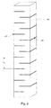
- FIG. 1 is a perspective view of a reservoir in accordance with an embodiment of the invention.
- FIG. 2 is a perspective view of a reservoir in accordance with an embodiment of the invention.
- FIG. 3 is a front elevation view of a prismatic reservoir in accordance with an embodiment of the invention.
- FIG. 4 is a front elevation view of a prismatic reservoir in accordance with an embodiment of the invention.
- FIG. 5 is an elevation view of a cylindrical reservoir in accordance with an embodiment of the invention.
- FIGS. 6A and 6B are elevation views of two configurations of a cylindrical reservoir in accordance with an embodiment of the invention.
- FIG. 7 graphically depicts loaded fluid release data for certain reservoirs of the invention.
- the present invention provides porous reservoirs that provide both high transport volume and high dissolution rates. This combination is accomplished through the use of lateral indentations, troughs or slits that serve to both increase the external surface area of the reservoir and reduce the lengths of continuous passages (capillaries) within the porous structure of the reservoir. As is discussed in more detail below, reducing continuous capillary length in the porous structure can, in many instances, be used to increase the transport volume of the reservoir despite a reduction in the void volume.
- the transport volume of a porous reservoir for a given loaded material is a function of the reservoir's material, internal structure, and overall geometry and on the environmental forces that must be countered in order to retain the loaded material.
- the most significant environmental force is gravity.
- Other environmental forces may include centrifugal acceleration and jarring or shock during movement of the reservoir.
- the porous reservoirs of the invention may be specifically configured to counter such environmental forces.
- the environmental forces tending to withdraw fluid from the reservoir are countered by the capillary forces (wicking strength) within the reservoir passages.
- the wicking strength which stems from interfacial surface tension forces, is dependant on the surface energy of the material defining the reservoir passages and on the geometry of the passages themselves. In particular, the wicking strength is proportional to capillary length.
- fluid means a substance whose molecules move freely past one another, including but not limited to a liquid or gas.
- fluid as used herein may also be multi-phase, and may include particulate matter suspended in a liquid or gas.
- capillarity determines how much capillary force is available to counter environmental forces such as gravity. For example, a reservoir's capillarity will determine how much fluid may be held within a continuous, generally vertically oriented capillary.
- the environmental force is substantially fixed (e.g., the force of gravity)
- capillarity can be expressed as the force-aligned length (i.e., the length component parallel to the force) of a continuous capillary that can retain fluid against the environmental force. Where the environmental force is gravity, the force-aligned length will be the height component of the capillary for a given reservoir orientation.
- the reservoir's capillarity one of the variables limiting the amount of fluid that can be retained against an environmental force is the reservoir's capillarity. If the reservoir has capillaries that are at least partially aligned with the environmental force and the cumulative length of the aligned portions of each such capillary is greater than the capillarity of the reservoir, then these capillaries will not be filled to their full capacity. This results in a reservoir that has an under-utilized void volume. It will be understood by those of ordinary skill in the art that such a reservoir could still be filled with fluid, but, over time, leakage will occur as the environmental force overcomes the capillarity of the reservoir.
- This problem may be countered by configuring the reservoir to reduce the number of capillaries having a length greater than the reservoir capillarity.
- One way this can be accomplished is to modify the overall dimensions of the reservoir so that the force-aligned length dimension is below a threshold where leakage will occur.
- the geometry of a reservoir may be configured so that its maximum dimension in a given direction is less than the capillarity.
- a reservoir intended to maintain a loaded fluid volume against gravity may be configured with a height that is less than the reservoir's capillarity. This approach will typically require that the reservoir's lateral dimensions be increased in order to maintain the desired void volume. While this may result in a large transport volume, it tends to produce reservoir geometries that do not lend themselves to rapid dissolution.
- the dissolution rate is the rate at which the contained material in the porous reservoir (i.e., the solute) dissolves when the reservoir is immersed in a solvent. Both diffusion and convection are important to the dissolution rate, with a combination of convection and diffusion normally providing a faster, more desirable dissolution rate than diffusion alone. Dissolution rates may typically be increased by increasing the surface area or surface to volume ratio of the reservoir and/or decreasing the cross sectional area or penetration distance of the reservoir.
- dissolution rates for a given reservoir material, a given loading material, and a given miscible receiving fluid are primarily a function of the external surface area of the reservoir across which the loaded material and the miscible receiving fluid are exchanged.
- the term “external surface area” refers to the hypothetical outer reservoir surface that would be established if the pores and passages of the reservoir were filled with solid.
- the term “internal surface area” is used herein to refer to the aggregate internal surfaces of the passages within the reservoir.
- a typical approach to maximizing surface area in an article such as a reservoir would be to provide a prismatic body having a high perimeter length cross-section (e.g., a multi-point star). This approach, however, significantly limits the relative volume available for material storage. For a given cross-section, increased volume could be obtained by lengthening the prism, but the effect on transport volume would be limited by the reservoir's capillarity.
- both the dissolution rate and the transport volume of a reservoir body may be increased by forming the reservoir with lateral indentations that may be in the form of cut-outs or slits oriented generally orthogonal to the direction of an environmental force (e.g., gravity or centrifugal force) to be countered by capillary forces.
- an environmental force e.g., gravity or centrifugal force
- the environmental force is assumed to be the force of gravity and force-aligned dimensions are expressed as height dimensions.
- FIG. 1 illustrates a reservoir 100 formed as a rectangular prism having an overall height H in the vertical direction, a width W and a depth D.
- the reservoir 100 has a plurality of slits 120 that cut laterally into the prism-shaped reservoir 100 .
- the term “slit” refers to an indentation having a height (i.e., dimension parallel to the environmental force) that ranges from 1 mm to 10 mm. In preferred embodiments, the slit height is at least 5 mm. It can be seen that without the slits 120 , the external surface area of the reservoir 100 would be 4HW+2HD. The slits 120 , however, each provide an increase in external surface area of approximately 2w s D. Depending on the geometry of the reservoir, the lateral indentations of the invention can produce nearly unlimited increases in surface area. In typical embodiments, increases in surface area from 1% to 200% are achieved.
- the slits 120 significantly increase external surface area without greatly reducing the reservoir volume.
- the dimensions and geometry of the reservoir 100 are such that the height dimensions of the capillaries within the reservoir 100 are greater than the capillarity of the reservoir 100 , then the lateral slits 120 will produce an even greater increase in the transport volume of the reservoir 100 .
- the slits 120 are oriented laterally with respect to the force of gravity g c when the reservoir 100 is oriented with it longitudinal axis 140 aligned with the gravity vector.
- any capillaries that intersect the slits 120 will be cut, thereby producing two shorter capillaries. This effectively reduces the vertical component of the capillary length.
- the amount of fluid that can be held by the split capillaries may be greater than the amount that could be held by the original un-split capillary. This effect translates to an increase in the overall transport volume of the reservoir.
- the increase in transport volume of the fluid will be highly dependent on the placement and geometry of the slits 120 .
- the slits 120 may alternately extend from opposing sides of the reservoir 100 as shown in FIG. 1 and may extend past the centerline of the reservoir 100 so that they “overlap.” The nearer to the opposite side the slits 120 extend, the greater the number of capillaries shortened. It can also be seen that the greater the number of slits 120 , the more effective the slits 120 will be in reducing capillary length throughout the reservoir 100 .
- FIG. 2 illustrates a reservoir 200 with a large number of slits 220 .
- transport volume can be maximized by assuring that the distance between adjacent slits on the same side of a reservoir body is less than the capillarity of the reservoir.
- the slits 220 can be formed in any number or combination of vertically or partially vertically oriented sides of the reservoir 200 . They can, for example, be formed or cut in adjacent or other non-opposing sides of the reservoir structure.
- slits 220 need not be exactly orthogonal to the gravitational or other force; they need only have an orthogonal component that will serve to interrupt the vertical length component of the reservoir capillaries. Accordingly, the slits 220 need not be straight horizontal lines.
- FIG. 3 illustrates a prismatic reservoir 300 having a plurality of slots 320 having similar lateral dimensions to the slits of the previous embodiments.
- the slots 320 also have a significant height dimension h s that represents the width of the slot. This has the effect of reducing the void volume in the reservoir 300 .
- spacing the lateral surfaces 322 , 324 of the slots 320 more than a minimal distance can assist in enhancing dissolution of material loaded in the reservoir 300 , particularly when assisted by lateral agitation or convection.
- the indentation (in this case, a slot) width w s is greater than half the reservoir width W, then the maximum vertical length of at least the majority of the capillaries intersecting the indentations 320 will be the distance between same-side indentations 320 , represented by h c . Accordingly, transport volume can be maximized by assuring that the distance between adjacent indentations/slots on the same side of a reservoir body is less than the capillarity of the reservoir.
- porous reservoirs of the invention may have laterally oriented indentations that are cylindrical, spherical, rectangular, triangular, flute shaped or any other regular or irregular, symmetric or asymetric shape.
- a prismatic reservoir 400 has a plurality of slots 420 formed as trapezoids. As in the preceding embodiment, the slots 420 have lateral surfaces 422 , 424 that increase external surface area and interrupt capillaries within the reservoir 400 .
- a cylindrical reservoir 500 has a single slit 520 that forms a spiral around the centerline 540 of the cylinder.
- FIGS. 6A and 6B Another variation on the spiral approach in shown in FIGS. 6A and 6B .
- a cylindrical reservoir 600 having a cylindrical center perforation 610 and a spiral slot 620 that extends from the outer surface of the cylinder all the way through to the center perforation 610 .
- this may be stretched to form the helical structure shown in FIG. 6B .
- Porous reservoirs in accordance with embodiments of the present invention may have a variety of overall geometries and sizes.
- a reservoir of the invention may be a cylinder, a prism, rectangle or any other shape.
- the porous reservoir may be sized and shaped to fit into a bottle or other fluid container. Any of these reservoirs, including prismatic reservoirs, may have one or more longitudinal perforations, which may be used to increase dissolution surface area or to allow for the mounting of the reservoir on a support structure such as a rod that extends from one or both ends of the reservoir for ease in handling the reservoir.
- reservoirs formed from relatively flexible or elastic materials may be elongated or otherwise deformed to change their geometry prior to use.
- the size and configuration of the lateral indentations may be used to facilitate such changes.
- the use of lateral indentation that extend across a majority of the lateral width of the reservoir may allow (or enhance) the ability of the reservoir to stretch in an accordion fashion.
- the lateral indentations in reservoirs of the invention may be integrally formed in the initial process of forming the reservoir structure.
- the lateral indentations may be established in a pre-formed porous reservoir, such as by shearing, drilling, cutting or milling material.
- the reservoir may be deformed either permanently, such as by stretching the reservoir beyond its yield point, or temporarily, for instance by putting the reservoir onto a curved rod or tube.
- the deformation may increase the external surface area of the lateral indentations of the reservoir thereby improving the dissolution rate of the reservoir.
- the reservoirs of the invention may be formed from any material that can be used to form a porous structure that uses capillary action to retain a material within the reservoir.
- Porous reservoirs may be formed of foam, cloth, non-woven fabrics, paper, and sponges.
- the reservoirs may also be made of one of many materials including, but not limited to, bundled and/or bonded or unbonded natural or man-made fibers, porous metal or plastic, and porous ceramic.
- reservoirs may be made of natural materials, such as natural sponges, cotton, linen and similar fiber-based parts. Also, some mineral based materials, such as pumice, asbestos, vermiculite, fused sand and fiber glass, may function as reservoir materials.
- bonded fiber structure type A structure type that is of particular utility in the reservoirs of the invention is the bonded fiber structure type.
- bonded fiber structures may be formed as three dimensional, self-sustaining structures that are particularly useful as wicks or reservoirs. In many instances, these structures are formed using bicomponent polymer fibers.
- bicomponent fiber As used herein, the term “bicomponent fiber” as used herein refers to the use of two polymers of different chemical nature placed in discrete portions of a fiber structure.
- bicomponent fibers comprising a core of one polymer and a coating or sheath of a different polymer are particularly desirable for many applications since the core material may be relatively inexpensive, providing the fiber with bulk and strength, while a relatively thin coating of a more expensive or less robust sheath material may provide the fiber with unique properties.
- Bicomponent fibers used to form reservoirs of the invention may be formed using any suitable method.
- the reservoirs formed from such fibers may be constructed by passing a bundle of fibers through a heated die to form a three dimensional, porous, self sustaining reservoir element.
- the bicomponent fiber may be a sheath-core bicomponent fiber, where the sheath polymer may serve as both a low melting material to facilitate bonding, and may have special properties (such as a specific surface energy) to create beneficial capillary properties.
- a reservoir in accordance with some embodiments of the present invention may alternatively be formed of monocomponent fibers, such as nylon or cellulose acetate, which may be bonded to form three dimensional, porous, self sustaining reservoir elements via the use of plasticizers to facilitate bonding with steam or other heat sources. Additionally, reservoirs may be three dimensional reservoirs formed of reticulated (open cell) polyurethane, or other elastomeric, foam. Other reservoirs in accordance with some' embodiments of the present invention may be sintered, porous plastics or ceramics.
- reservoirs in accordance with some embodiments of the present invention may include a channel (a hole) through the core or inner area of the reservoir that extends from the upper portion of the reservoir to a lower portion of the reservoir.
- the channel may be of sufficient shape and/or size to accommodate a rod, tube, dip tube or any other insertion device.
- the dip tube of a spray bottle may be inserted through the channel of the reservoir.
- the reservoir will retain a fluid or solid until the dip tube is inserted in the spray bottle and the reservoir contacts the contents of the spray bottle.
- the fluid or solid within the reservoir will rapidly dissolve in the contents of the spray bottle.
- agitation of the spray bottle or the reservoir will improve the dissolution rate of the reservoir.
- the reservoirs of the invention may be configured so as to counter environmental forces in more than a single direction.
- different indentation sets may be configured to be “lateral” with respect to different anticipated force directions.
- the geometry of the reservoir may be configured with an increased overall length in that direction.
- the dimensions of the reservoir in other directions may be specifically configured to be less than the reservoir capillarity.
- a cylindrical reservoir intended to provide enhanced vertical leakage performance may be configured with a relatively large axial dimension and a small diameter. The axial dimension could be of any length so long as sufficient lateral indentations are provided to reduce the vertical capillary lengths when the reservoir is stood on end.
- the diameter is shorter than the capillarity, the reservoir will not leak when the cylinder is placed on its side.
- a cylindrical bonded bicomponent polyolefin fiber reservoir structure with nominally 85% void volume, about 70 mm long and about 24 mm in diameter with a 4 mm diameter hole through its longitudinal center was made.
- the reservoir shape was formed in a die under length-oriented tension using steam as the heating medium, and then cut to length. The reservoir was elastic enough to recover completely from a 5% extension.
- the external diameter of the reservoir was sized to fit into the neck of a typical spray bottle.
- the diameter of the channel or hole of the reservoir was sized to accommodate the 4 mm o.d. dip tube of a typical household cleaner spray nozzle.
- the capillary strength of the reservoir was sufficient to hold about 17 grams of a cleaner concentrate solution.
- the reservoir included partial thickness slits (i.e., lateral indentations having essentially zero height) along the length of the reservoir alternating on each side with 5 mm spacing between slits.
- the slit depth extended to a point immediately through the channel or hole.
- the slits provided an additional exterior surface area (increasing the quantity of area for dissolution) and were perpendicular to the long axis (dip tube axis) of the reservoir.
- the reservoir was inserted onto the dip tube using the channel or hole in the core/interior of the reservoir, and the dip tube was inserted into the spray bottle containing water. As the dip tube was inserted a spray nozzle was attached. When inserted in the spray bottle, the dip tube flexed to fit into a corner of the bottle bottom. The reservoir lengthened and the lengthening of the reservoir widened the slits of the reservoir, which served to enhance dissolution of the ‘concentrate’ into the water.
- the bottle was agitated by inverting and then righting six times, then allowed to stand.
- the cleaner concentrate was dyed, with the dye having an absorbance maximum at 550 nm. Aliquots were take from the bottle at 1, 5, 10, 20, 30 and 35 minute increments, and the absorbance measured in a UV/Vis spectrophotometer to quantitatively measure the amount of concentrate released into the bulk water in the bottle.
- FIG. 7 graphically depicts the results versus time as compared to a similar reservoir with no slits. Throughout the test period the slit reservoir exhibited a dissolution rate more than twice that of the un-slit reservoir.
- Example 1 The reservoir of Example 1 was stretched beyond a yield point of the reservoir material, thereby extending the original length and causing the slits to open. The reservoir was stretched to twice its original length dimension, thereby producing wider slit openings.
- the elongated reservoir was mounted on a dip tube and placed in a spray bottle, following a process similar to that outlined in Example 1. The reservoir experienced improved concentrate release characteristics when compared to a comparable reservoir without slits. Throughout the test period, the slit/extended reservoir exhibited a dissolution rate more than twice that of an un-slit reservoir. The results for dissolution versus time were similar to the reservoir of Example 1.
Landscapes
- Chemical & Material Sciences (AREA)
- Chemical Kinetics & Catalysis (AREA)
- Containers And Packaging Bodies Having A Special Means To Remove Contents (AREA)
- Infusion, Injection, And Reservoir Apparatuses (AREA)
Abstract
Description
Claims (25)
Priority Applications (2)
| Application Number | Priority Date | Filing Date | Title |
|---|---|---|---|
| US11/857,788 US8334034B2 (en) | 2006-09-27 | 2007-09-19 | Rapid release and anti-drip porous reservoirs |
| PCT/US2007/079013 WO2008039685A2 (en) | 2006-09-27 | 2007-09-20 | Rapid release and anti-drip porous reservoirs |
Applications Claiming Priority (2)
| Application Number | Priority Date | Filing Date | Title |
|---|---|---|---|
| US84745406P | 2006-09-27 | 2006-09-27 | |
| US11/857,788 US8334034B2 (en) | 2006-09-27 | 2007-09-19 | Rapid release and anti-drip porous reservoirs |
Publications (2)
| Publication Number | Publication Date |
|---|---|
| US20080073226A1 US20080073226A1 (en) | 2008-03-27 |
| US8334034B2 true US8334034B2 (en) | 2012-12-18 |
Family
ID=39223758
Family Applications (1)
| Application Number | Title | Priority Date | Filing Date |
|---|---|---|---|
| US11/857,788 Expired - Fee Related US8334034B2 (en) | 2006-09-27 | 2007-09-19 | Rapid release and anti-drip porous reservoirs |
Country Status (2)
| Country | Link |
|---|---|
| US (1) | US8334034B2 (en) |
| WO (1) | WO2008039685A2 (en) |
Families Citing this family (2)
| Publication number | Priority date | Publication date | Assignee | Title |
|---|---|---|---|---|
| GB201407056D0 (en) | 2014-04-22 | 2014-06-04 | Essentra Filter Products Dev Co Pte Ltd | Smoking article |
| CN111578271A (en) * | 2020-05-09 | 2020-08-25 | 苏州北美国际高级中学 | Novel safe alcohol lamp and preparation method thereof |
Citations (14)
| Publication number | Priority date | Publication date | Assignee | Title |
|---|---|---|---|---|
| US3113336A (en) | 1962-01-03 | 1963-12-10 | Langnickel Arvid | Ink marker |
| US4968169A (en) | 1987-06-26 | 1990-11-06 | Pilot Ink Co., Ltd. | Penpoint assembly and writing instrument employing the same |
| US5433545A (en) | 1991-04-16 | 1995-07-18 | Merz & Krell Gmbh & Co. | Writing implement |
| US5607766A (en) | 1993-03-30 | 1997-03-04 | American Filtrona Corporation | Polyethylene terephthalate sheath/thermoplastic polymer core bicomponent fibers, method of making same and products formed therefrom |
| WO1998009016A1 (en) | 1996-08-30 | 1998-03-05 | Kimberly-Clark Worldwide, Inc. | Permeable, liquid flow control material |
| US6103181A (en) | 1999-02-17 | 2000-08-15 | Filtrona International Limited | Method and apparatus for spinning a web of mixed fibers, and products produced therefrom |
| US6244744B1 (en) | 1998-05-20 | 2001-06-12 | James Calvin | Three-wire RTD interface |
| US6250511B1 (en) | 1999-11-05 | 2001-06-26 | Albert R. Kelly | Recharge insert for cleaning, sanitizing or disinfectant fluid spray system |
| US6330883B1 (en) | 1999-02-17 | 2001-12-18 | Filtrona Richmond, Inc. | Heat and moisture exchanger comprising hydrophilic nylon and methods of using same |
| US6758040B1 (en) | 2002-01-03 | 2004-07-06 | Valeriano Cantu | High heat producing power system |
| US6840692B2 (en) | 2002-04-10 | 2005-01-11 | Filtrona Richmond, Inc. | Method and apparatus for making NIBS and ink reservoirs for writing and marking instruments and the resultant products |
| US20050189292A1 (en) | 2004-03-01 | 2005-09-01 | Filtrona Richmond, Inc. | Bicomponent fiber wick |
| US7018031B2 (en) | 2002-12-23 | 2006-03-28 | Filtrona Richmond, Inc. | Porous substrate for ink delivery systems |
| US7416667B2 (en) * | 2000-09-07 | 2008-08-26 | Prosep Inc. | Polyurethane oil de-emulsification unit |
Family Cites Families (2)
| Publication number | Priority date | Publication date | Assignee | Title |
|---|---|---|---|---|
| DE4237616A1 (en) * | 1992-11-06 | 1994-05-11 | Merz & Krell | Capillary-ink storage system |
| US6768040B1 (en) * | 2000-03-27 | 2004-07-27 | Ferris Pharmaceuticals Inc. | Wound dressing for treating injury to nasal passages |
-
2007
- 2007-09-19 US US11/857,788 patent/US8334034B2/en not_active Expired - Fee Related
- 2007-09-20 WO PCT/US2007/079013 patent/WO2008039685A2/en active Application Filing
Patent Citations (16)
| Publication number | Priority date | Publication date | Assignee | Title |
|---|---|---|---|---|
| US3113336A (en) | 1962-01-03 | 1963-12-10 | Langnickel Arvid | Ink marker |
| US4968169A (en) | 1987-06-26 | 1990-11-06 | Pilot Ink Co., Ltd. | Penpoint assembly and writing instrument employing the same |
| US5433545A (en) | 1991-04-16 | 1995-07-18 | Merz & Krell Gmbh & Co. | Writing implement |
| US5607766A (en) | 1993-03-30 | 1997-03-04 | American Filtrona Corporation | Polyethylene terephthalate sheath/thermoplastic polymer core bicomponent fibers, method of making same and products formed therefrom |
| US5620641A (en) | 1995-06-06 | 1997-04-15 | American Filtrona Corporation | Polyethylene terephthalate sheath/thermoplastic polymer core bicomponent fibers, method of making same and products formed therefrom |
| US5633082A (en) | 1995-06-06 | 1997-05-27 | American Filtrona Corporation | Polyethylene terephthalate sheath/thermoplastic polymer core bicomponent fibers, method of making same and products formed therefrom |
| WO1998009016A1 (en) | 1996-08-30 | 1998-03-05 | Kimberly-Clark Worldwide, Inc. | Permeable, liquid flow control material |
| US6244744B1 (en) | 1998-05-20 | 2001-06-12 | James Calvin | Three-wire RTD interface |
| US6103181A (en) | 1999-02-17 | 2000-08-15 | Filtrona International Limited | Method and apparatus for spinning a web of mixed fibers, and products produced therefrom |
| US6330883B1 (en) | 1999-02-17 | 2001-12-18 | Filtrona Richmond, Inc. | Heat and moisture exchanger comprising hydrophilic nylon and methods of using same |
| US6250511B1 (en) | 1999-11-05 | 2001-06-26 | Albert R. Kelly | Recharge insert for cleaning, sanitizing or disinfectant fluid spray system |
| US7416667B2 (en) * | 2000-09-07 | 2008-08-26 | Prosep Inc. | Polyurethane oil de-emulsification unit |
| US6758040B1 (en) | 2002-01-03 | 2004-07-06 | Valeriano Cantu | High heat producing power system |
| US6840692B2 (en) | 2002-04-10 | 2005-01-11 | Filtrona Richmond, Inc. | Method and apparatus for making NIBS and ink reservoirs for writing and marking instruments and the resultant products |
| US7018031B2 (en) | 2002-12-23 | 2006-03-28 | Filtrona Richmond, Inc. | Porous substrate for ink delivery systems |
| US20050189292A1 (en) | 2004-03-01 | 2005-09-01 | Filtrona Richmond, Inc. | Bicomponent fiber wick |
Also Published As
| Publication number | Publication date |
|---|---|
| US20080073226A1 (en) | 2008-03-27 |
| WO2008039685A3 (en) | 2008-07-24 |
| WO2008039685A2 (en) | 2008-04-03 |
Similar Documents
| Publication | Publication Date | Title |
|---|---|---|
| US5042978A (en) | Container using a mass of porous material for liquid retention | |
| KR930012035B1 (en) | Back filter dust collector | |
| EP3664631B1 (en) | Cartridge for a vaporizer device | |
| US8334034B2 (en) | Rapid release and anti-drip porous reservoirs | |
| US20200128874A1 (en) | Cartridge for a vaporizer device | |
| Benner et al. | Potential flow in the presence of a sudden expansion: Application to capillary driven transport in porous media | |
| JP5859164B1 (en) | Applicator | |
| EP1222431B1 (en) | Moisture absorption apparatus | |
| US8047453B2 (en) | Neutral displacement wick | |
| JP2017036051A (en) | Applicator | |
| Mao et al. | Anisotropic liquid absorption in homogeneous two-dimensional nonwoven structures | |
| WO2020176902A2 (en) | Cartridge for a vaporizer device | |
| CN110325736A (en) | For including the surface for overcoming the orientation fluid conveying of external pressure | |
| US9056144B1 (en) | Non-clogging, non-dripping and spillage and leakage-proof air-scenting method and device | |
| KR101683758B1 (en) | Suction nozzle | |
| MY | Wetting phenomena in fibrous materials | |
| CN108884841A (en) | For orienting the surface of fluid conveying | |
| US8517283B1 (en) | Non-clogging, non-dripping and spillage and leakage-proof air-scenting method and device | |
| US9114558B1 (en) | Method of making a non-clogging porous fibrous mass for air scenting | |
| CN214159400U (en) | Powder bottle vibrating device | |
| JP2013031939A (en) | Fluid supply device | |
| US8464965B1 (en) | Non-dripping and spillage and leakage-proof air-scenting method and device | |
| JP6632515B2 (en) | Processing pile holder | |
| Antar | Development of liquid handling techniques in microgravity | |
| JP2001242184A (en) | Method for cleaning of dispensing needle for forming sample chip |
Legal Events
| Date | Code | Title | Description |
|---|---|---|---|
| AS | Assignment |
Owner name: FILTRONA RICHMOND, INC., VIRGINIA Free format text: ASSIGNMENT OF ASSIGNORS INTEREST;ASSIGNORS:STOLTZ, GEOFFREY M.;WARD, BENNETT C.;BINSHTOK, RONALD J.;REEL/FRAME:020168/0370 Effective date: 20071029 Owner name: FILTRONA RICHMOND, INC., VIRGINIA Free format text: ASSIGNMENT OF ASSIGNORS INTEREST;ASSIGNOR:LISK, JAMES R.;REEL/FRAME:020168/0416 Effective date: 20071115 |
|
| AS | Assignment |
Owner name: FILTRONA POROUS TECHNOLOGIES CORP., VIRGINIA Free format text: ASSIGNMENT OF ASSIGNORS INTEREST;ASSIGNOR:FILTRONA RICHMOND, INC.;REEL/FRAME:025544/0202 Effective date: 20101210 |
|
| STCF | Information on status: patent grant |
Free format text: PATENTED CASE |
|
| AS | Assignment |
Owner name: ESSENTRA POROUS TECHNOLOGIES CORP., VIRGINIA Free format text: CHANGE OF NAME;ASSIGNOR:FILTRONA POROUS TECHNOLOGIES CORP.;REEL/FRAME:031409/0011 Effective date: 20131014 |
|
| FPAY | Fee payment |
Year of fee payment: 4 |
|
| AS | Assignment |
Owner name: GOLDMAN SACHS BANK USA, AS COLLATERAL AGENT, NEW J Free format text: SECURITY INTEREST;ASSIGNOR:POREX TECHNOLOGIES CORPORATION, F/K/A, ESSENTRA POROUS TECHNOLOGIES CORP.;REEL/FRAME:042461/0917 Effective date: 20170406 Owner name: POREX TECHNOLOGIES CORPORATION, VIRGINIA Free format text: CHANGE OF NAME;ASSIGNOR:ESSENTRA POROUS TECHNOLOGIES CORP.;REEL/FRAME:042528/0180 Effective date: 20170306 |
|
| AS | Assignment |
Owner name: GOLDMAN SACHS BANK USA, AS COLLATERAL AGENT, NEW JERSEY Free format text: SECURITY INTEREST;ASSIGNORS:AG INDUSTRIES LLC;AIR SYSTEM PRODUCTS LLC;CHEMCO MANUFACTURING CO., INC.;AND OTHERS;REEL/FRAME:045768/0001 Effective date: 20180329 Owner name: GOLDMAN SACHS BANK USA, AS COLLATERAL AGENT, NEW J Free format text: SECURITY INTEREST;ASSIGNORS:AG INDUSTRIES LLC;AIR SYSTEM PRODUCTS LLC;CHEMCO MANUFACTURING CO., INC.;AND OTHERS;REEL/FRAME:045768/0001 Effective date: 20180329 |
|
| AS | Assignment |
Owner name: POREX TECHNOLOGIES CORPORATION F/K/A ESSENTRA PORO Free format text: RELEASE BY SECURED PARTY;ASSIGNOR:GOLDMAN SACHS BANK USA, AS COLLATERAL AGENT;REEL/FRAME:045393/0092 Effective date: 20180329 |
|
| FEPP | Fee payment procedure |
Free format text: MAINTENANCE FEE REMINDER MAILED (ORIGINAL EVENT CODE: REM.); ENTITY STATUS OF PATENT OWNER: LARGE ENTITY |
|
| LAPS | Lapse for failure to pay maintenance fees |
Free format text: PATENT EXPIRED FOR FAILURE TO PAY MAINTENANCE FEES (ORIGINAL EVENT CODE: EXP.); ENTITY STATUS OF PATENT OWNER: LARGE ENTITY |
|
| STCH | Information on status: patent discontinuation |
Free format text: PATENT EXPIRED DUE TO NONPAYMENT OF MAINTENANCE FEES UNDER 37 CFR 1.362 |
|
| FP | Lapsed due to failure to pay maintenance fee |
Effective date: 20201218 |