US8331889B2 - Automatic fuse architecture - Google Patents
Automatic fuse architecture Download PDFInfo
- Publication number
- US8331889B2 US8331889B2 US11/757,956 US75795607A US8331889B2 US 8331889 B2 US8331889 B2 US 8331889B2 US 75795607 A US75795607 A US 75795607A US 8331889 B2 US8331889 B2 US 8331889B2
- Authority
- US
- United States
- Prior art keywords
- signal
- power
- recited
- diversity antenna
- threshold value
- Prior art date
- Legal status (The legal status is an assumption and is not a legal conclusion. Google has not performed a legal analysis and makes no representation as to the accuracy of the status listed.)
- Active, expires
Links
- 238000010897 surface acoustic wave method Methods 0.000 claims description 29
- 230000007246 mechanism Effects 0.000 claims description 26
- 238000000034 method Methods 0.000 claims description 19
- 238000012545 processing Methods 0.000 claims description 9
- 238000001514 detection method Methods 0.000 claims description 4
- 230000004044 response Effects 0.000 claims description 2
- 230000001419 dependent effect Effects 0.000 claims 2
- 238000002955 isolation Methods 0.000 description 15
- 230000002159 abnormal effect Effects 0.000 description 11
- 230000001413 cellular effect Effects 0.000 description 8
- 238000005562 fading Methods 0.000 description 6
- 230000008569 process Effects 0.000 description 6
- 230000005540 biological transmission Effects 0.000 description 5
- 230000006378 damage Effects 0.000 description 4
- 230000000694 effects Effects 0.000 description 4
- 230000008901 benefit Effects 0.000 description 3
- 238000004891 communication Methods 0.000 description 3
- 238000013461 design Methods 0.000 description 3
- 238000010295 mobile communication Methods 0.000 description 3
- 238000012546 transfer Methods 0.000 description 3
- 239000002184 metal Substances 0.000 description 2
- 230000007420 reactivation Effects 0.000 description 2
- 230000009467 reduction Effects 0.000 description 2
- 230000005856 abnormality Effects 0.000 description 1
- 230000009471 action Effects 0.000 description 1
- 230000015556 catabolic process Effects 0.000 description 1
- 230000007423 decrease Effects 0.000 description 1
- 230000003247 decreasing effect Effects 0.000 description 1
- 238000006731 degradation reaction Methods 0.000 description 1
- 230000009977 dual effect Effects 0.000 description 1
- 238000011156 evaluation Methods 0.000 description 1
- 230000003993 interaction Effects 0.000 description 1
- 239000004973 liquid crystal related substance Substances 0.000 description 1
- 230000000135 prohibitive effect Effects 0.000 description 1
Images


Classifications
-
- H—ELECTRICITY
- H04—ELECTRIC COMMUNICATION TECHNIQUE
- H04B—TRANSMISSION
- H04B1/00—Details of transmission systems, not covered by a single one of groups H04B3/00 - H04B13/00; Details of transmission systems not characterised by the medium used for transmission
- H04B1/06—Receivers
- H04B1/10—Means associated with receiver for limiting or suppressing noise or interference
- H04B1/109—Means associated with receiver for limiting or suppressing noise or interference by improving strong signal performance of the receiver when strong unwanted signals are present at the receiver input
Definitions
- HSDPA High Speed Downlink Packet Access
- HSUPA High Speed Uplink Packet Access
- UMTS Universal Mobile Telecommunications System
- the signal quality and range may be enhanced by increasing the number of base stations in order to reduce the maximum distance between a given base station and the mobile device. For example, in a cellular network system, increasing the number of cellular towers effectively decreases the distance between a given mobile device in the network and the nearest cellular tower. However, this solution would be cost prohibitive due in part to the high cost of installing and maintaining additional base stations.
- the range of high data rate transfer within a communication system may also be increased using a primary antenna with a diversity antenna to create two receiver chains within the mobile device.
- the primary antenna sends and receives signals, whereas the diversity antenna is dedicated to signal reception.
- the diversity antenna complements the primary antenna by preventing fading, where fading is defined by a reduction of signal quality and/or transmission rate.
- the diversity antenna typically experiences an isolation effect with the primary antenna.
- the isolation effect may reduce the TX power of the signal that is received by the diversity antenna.
- a diversity antenna switch associated with the diversity antenna may be designed to take advantage of this isolation effect.
- the so-called “front end” of the switch may be optimized by omitting typical primary filter components, such as the duplex filter and external low noise amplifier (LNA). Omitting these components results in cost and space savings, as well as other benefits.
- LNA low noise amplifier
- the lack of the duplex filter and other front end components in the diversity receiver is acceptable due to the isolation that occurs between the primary antenna and the diversity antenna, which limits the signal power received by diversity antenna.
- the isolation between the primary antenna and diversity antenna can be dramatically lowered.
- the abnormal conditions may be caused by placing the diversity antenna too close to, or on, a metal plate or by other abnormalities that the mobile device may experience.
- relatively fragile and power sensitive components such as a Surface Acoustic Wave (SAW) filter associated with the diversity antenna, may be exposed to power levels close to, or equal to, the fully transmitted signal power. The excessive signal power may damage or even destroy these components.
- SAW Surface Acoustic Wave
- FIG. 1 shows an exemplary base station and exemplary mobile devices for sending and receiving transmissions.
- FIG. 2 shows an exemplary system having a primary antenna and a diversity antenna.
- FIG. 3 shows an exemplary method of operating a diversity antenna with a detector.
- This disclosure describes the design and use of a switch for preventing a signal from reaching power sensitive components, such as filter elements, active devices and/or passive devices and so forth, under certain abnormal conditions.
- power sensitive components include SAW filters, tunable filters, tunable matching circuits, isolators, circulators, Low Noise Amplifiers (LNAs), mixers, Analog-to-Digital Converter (ADCs), diplexers, and so forth.
- LNAs Low Noise Amplifiers
- ADCs Analog-to-Digital Converter
- a diversity antenna system has an antenna switch to direct an incoming signal to one or more filter elements, where each filter element may handle a signal related to a particular signal frequency.
- the antenna switch may also have a detector to sense the power of the incoming signal. If the detector detects that the signal exceeds a predetermined threshold, the signal may be prevented from reaching the filter elements by directing the signal to a termination point.
- a device that receives an incoming signal from an antenna and outputs a signal to control logic.
- the device also includes a detection mechanism operable to determine the power of the incoming signal from the antenna and to communicate a signal to the control logic to direct the signal to either the filter or the termination point based upon the power of the incoming signal measured by the detector.
- a method includes detecting an incoming signal received by an antenna. If the signal is below a predetermined threshold, the signal may be directed to a filter element. If the signal exceeds the predetermined threshold, the signal may be directed to a termination point.
- FIG. 1 shows a mobile communication system 100 having a base station 102 and one or more mobile devices 104 or 106 .
- the mobile communication system 100 is representative of a cellular network, in which the base station 102 represents a cellular phone tower or other device capable of transmitting and/or receiving one or more radio or other wireless signals 108 within a cell of a cellular network.
- the mobile devices 104 and 106 represent cellular phones, wireless media devices, or other devices capable of receiving and/or transmitting a radio or other wireless signal 108 .
- the mobile device 104 or 106 may alternatively be a personal digital assistant (PDA), a portable computing device capable of wireless communication, a media player device, a portable gaming device, and/or a wireless access point (WAP).
- PDA personal digital assistant
- WAP wireless access point
- Mobile devices 104 and 106 may be identical, with mobile device 104 representing a device operating under normal conditions and mobile device 106 representing a device operating under abnormal conditions.
- the abnormal conditions may be caused, for example, by placing the mobile device 106 too near, or on, a metal plate 110 , a human body, or other obstacle.
- mobile device 104 will be used for reference and any description thereof is applicable to mobile device 106 , unless otherwise indicated.
- the mobile device 104 includes an antenna 112 to communicate with the base station 102 .
- Antenna 112 may be configured to transmit and/or receive the signal 108 and may represent a primary antenna and/or a diversity antenna.
- the signal 108 may initially be processed by antenna components 114 , which may include filters, receivers, transmitters, and so forth.
- the antenna components may send the signal to processing circuitry 116 .
- a battery 118 provides power to the processing circuitry 116 and other components of the mobile device 104 .
- the mobile device 104 may also have components for user interaction, such as a display 120 (e.g., liquid crystal display), a keypad 122 , a microphone 124 , and/or a speaker 126 .
- the signal quality may be limited by a number of factors, including thermal noise, the noise figure of the receiver, and the channel quality (fading).
- the limited signal quality may limit reliable data transfer, particularly for high rate data transfers, such as may be required for video transmission as well as for communication of internet content.
- the signal quality may improve by decreasing the distance between the mobile device and the base station by, for example one-half, as denoted by the distance “1 ⁇ 2X” in FIG. 1 .
- the antenna 112 includes a primary antenna and a diversity antenna with antenna components 114 supporting the two antennas.
- the primary antenna sends and receives signals, whereas the diversity antenna is dedicated to signal reception.
- the diversity antenna complements the primary antenna by preventing fading, where fading is defined by a reduction of signal quality and/or transmission rate.
- FIG. 2 shows an exemplary dual-antenna structure 200 with a primary antenna 202 and a diversity antenna 204 .
- the primary antenna 202 transmits and/or receives signals using primary antenna components 206 , which may include a transmitter, receiver, filters, and so forth.
- the diversity antenna 204 is dedicated to signal reception and complements the primary antenna 202 by preventing fading.
- the diversity antenna 204 includes a diversity antenna switch 208 to direct signals to power sensitive components, such as filters, active and passive devices, and so forth.
- the antenna switch 204 may direct signals to different filter elements in a Surface Acoustic Wave (SAW) filter mechanism 210 based on the frequency of the signal.
- SAW Surface Acoustic Wave
- the outputs of the primary antenna components 206 and/or the SAW filter mechanism 210 are transmitted to further circuitry of a mobile device, such as processing circuitry 116 ( FIG. 1 ). Such circuitry would be within the knowledge of one of skill in the art and is not shown for the sake of simplicity. Likewise, well-known components associated with the antennas, such as so-called “matching” components in the SAW filter mechanisms, are not shown or described in detail herein as their configuration is not critical to this discussion.
- the signal power at the primary antenna 202 may not generally be realized by the diversity antenna 204 due to isolation between the antennas.
- the extent of this isolation depends on the design of structure 200 .
- the antennas 202 and 204 may be designed for minimal isolation in order to optimize diversity performance. For example, in normal operation, approximately 10 decibel (dB) of isolation attributable to isolation may be present between the two antennas.
- the diversity switch 208 may be designed to take advantage of the isolation effect. For example, since the diversity antenna 208 is affected by isolation, certain components, such as the duplex filter and external low noise amplifier (LNA), are omitted from the front end of the switch 208
- a typical transmission may be transmitted at about 25 dBm (Decibel referenced to milliwatts).
- the diversity antenna 204 generally receives an input power of 15 dBm.
- Any given filter element in the SAW filter mechanism 210 typically has a maximum input power of 15 dBm.
- the actual power input into the SAW filter mechanism 210 is less than, or equal to, the maximum power that can be handled by any of the filter elements in the SAW filter mechanism 210 .
- the SAW filter mechanism 210 is capable of handling the level of power received by diversity antenna 204 without being damaged.
- the isolation between the primary antenna 202 and diversity antenna 204 may be dramatically reduced which increases the power of the signal sent to the SAW filter mechanism 210 .
- the filter elements in the SAW filter mechanism 210 may be exposed to power levels close, or equal, to the fully transmitted power.
- the filter elements in the SAW filter mechanism 210 may be exposed to, for example, 25 dBm rather than the 15 dBm for which the filters in SAW filter mechanism 210 are designed. This excessive signal power might potentially damage or even destroy the SAW filter mechanism 210 .
- a detector 212 is inserted between the diversity antenna 204 and the SAW filter mechanism 210 .
- the detector 212 may have an input terminal 214 to receive an incoming signal from the antenna and an output terminal 216 connected to control logic 218 .
- the detector 212 may be operable to determine whether the input signal has a power that exceeds a threshold value.
- the threshold value may be based, for example, upon the power handling capabilities of the filter elements in the SAW filter mechanism 210 . If the signal power exceeds the threshold value, the detector 212 informs the control logic 218 , which prevents the signal from reaching the SAW filter mechanism 210 .
- control logic 218 directs a switch 220 to send the signal received by antenna 204 to one of several electrical portals 222 .
- Each portal 222 connects to a different SAW filter element in the SAW filter mechanism 210 or to a termination point 224 , which may be a load, open, ground, or “off” mode connection.
- a termination point 224 which may be a load, open, ground, or “off” mode connection.
- six portals 222 are shown in FIG. 2 and are configured to handle five frequency bands and the termination point 224 .
- the control logic 218 may be controlled by three-bit control signals generated by a signal generator 226 associated with a processing unit 228 as is well known in the art. Control logic 218 includes hardware, software, or a combination thereof.
- the three-bit control signal may include three individual digital signals.
- Each incoming digital signal is either high (1) or low (0), enabling multiple three-bit signal combinations including, for example: [000], [001], [011], [111], [110], [100], [010], and [101].
- Each digital signal combination may direct the switching mechanism 220 to a different portal 222 in the diversity antenna switch 208 .
- a three bit signal of [000] may direct the switching mechanism 220 such that the signal from the antenna 204 travels to the termination point 224 .
- a control signal corresponding to [001] may direct the switching mechanism 220 such that the signal is directed from the antenna 204 to Band I, which may correspond to a filter for handling a ⁇ 2100 MHz frequency signal, and so forth.
- the switching mechanism may be directed to any number of paths by increasing the number of bits processed by the control logic 218 and increasing the number of portals 222 .
- the detector 212 or the control logic 218 directs the switching mechanism 220 to a termination point 224 .
- the termination point 224 may be a ground, load, open circuit, or “off” mode connection.
- the detector 212 may be a diode that operates either as a short or as an open circuit depending on whether the incoming signal exceeds the threshold power value. Thus, when the signal received by the detector 212 exceeds the threshold value, the detector sends a signal to the control logic 218 to direct the switch 220 to the termination point 224 .
- the detector may send no signal to the control logic 218 , thereby acting as an open circuit. Additionally or alternatively, the diode may connect directly to the termination point (i.e. not through the control logic) such that the detector operates as an open circuit under normal conditions and as a short to the termination point under abnormal conditions.
- the termination point 224 may be an “off” mode connection that sends an “off” signal back to the processing unit 228 .
- the processing unit 228 may render the mobile device, or a portion of the device, inoperable for a predetermined period.
- the predetermined period may be based upon a preselected passage of time (e.g., 30 seconds), the cessation of the abnormal condition, or the reactivation of the device by a user. Reactivation may involve pressing a power button on the device, resetting the battery, or other action by the user.
- the “off” mode connection may be in addition to, or as an alternative to, a load or ground termination.
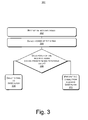
- FIG. 3 shows an exemplary process 300 of detecting power incoming to a diversity antenna and, in response, preventing the power from reaching filters.
- This process 300 may be implemented with the antenna structure shown in FIG. 2 , though the process is not limited to such an implementation.
- the process is illustrated as a collection of referenced acts arranged in a logical flow graph, which represent a sequence that can be implemented in hardware, software, or a combination thereof.
- the acts represent computer-executable instructions that, when executed, perform the recited operations.
- the order in which the acts are described is not intended to be construed as a limitation, and any number of the described acts can be combined in any order and/or in parallel to implement the process 300 .
- an incoming signal is received. More particularly, the signal may be received by an antenna, such as a primary antenna and/or a diversity antenna.
- the received signal is sent to a switch.
- the switch may be designed to direct the signal incoming from the antenna (e.g. the diversity antenna) to one or more ports connected to SAW filters, where each port corresponds to a different signal frequency.
- the signal is detected to evaluate, measure, and/or determine its characteristics.
- a detector 212 may be inserted in, or associated with, the antenna switch to assist in this evaluation.
- the detector 212 may include a diode to determine the signal's power.
- the power of the incoming signal exceeds a predetermined threshold value is determined. If the power does not exceed the predetermined threshold value, the signal is directed toward the SAW filters at 308 . However, if the power exceeds the predetermined threshold value, the signal is prevented from reaching the SAW filters at 310 . The signal is prevented from reaching the SAW filters by, for example, sending the signal to a termination point, such as a load, ground, open, or “off” mode connection. The process may be automatic, such that the detector acts as fuse to automatically direct the signal to the termination point if the detected power exceeds the threshold value. According to this exemplary method, SAW filters associated with the antenna switch are protected from damage or destruction.
Landscapes
- Engineering & Computer Science (AREA)
- Computer Networks & Wireless Communication (AREA)
- Signal Processing (AREA)
- Mobile Radio Communication Systems (AREA)
- Transceivers (AREA)
- Input Circuits Of Receivers And Coupling Of Receivers And Audio Equipment (AREA)
- Radio Transmission System (AREA)
Abstract
Description
Claims (17)
Priority Applications (2)
| Application Number | Priority Date | Filing Date | Title |
|---|---|---|---|
| US11/757,956 US8331889B2 (en) | 2007-06-04 | 2007-06-04 | Automatic fuse architecture |
| DE102008026524.1A DE102008026524B4 (en) | 2007-06-04 | 2008-06-03 | Automatic backup architecture |
Applications Claiming Priority (1)
| Application Number | Priority Date | Filing Date | Title |
|---|---|---|---|
| US11/757,956 US8331889B2 (en) | 2007-06-04 | 2007-06-04 | Automatic fuse architecture |
Publications (2)
| Publication Number | Publication Date |
|---|---|
| US20080300021A1 US20080300021A1 (en) | 2008-12-04 |
| US8331889B2 true US8331889B2 (en) | 2012-12-11 |
Family
ID=39986378
Family Applications (1)
| Application Number | Title | Priority Date | Filing Date |
|---|---|---|---|
| US11/757,956 Active 2029-07-06 US8331889B2 (en) | 2007-06-04 | 2007-06-04 | Automatic fuse architecture |
Country Status (2)
| Country | Link |
|---|---|
| US (1) | US8331889B2 (en) |
| DE (1) | DE102008026524B4 (en) |
Cited By (3)
| Publication number | Priority date | Publication date | Assignee | Title |
|---|---|---|---|---|
| US20130002498A1 (en) * | 2009-02-05 | 2013-01-03 | Research In Motion Limited | Mobile wireless communications device having diversity antenna system and related methods |
| CN104348438A (en) * | 2013-07-30 | 2015-02-11 | 英特尔Ip公司 | Apparatus and method for determining information on a power variation of a transmit signal |
| US10454511B2 (en) * | 2007-09-26 | 2019-10-22 | Intel Mobile Communications GmbH | Radio-frequency front-end and receiver |
Families Citing this family (4)
| Publication number | Priority date | Publication date | Assignee | Title |
|---|---|---|---|---|
| US8892057B2 (en) * | 2011-08-23 | 2014-11-18 | Rf Micro Devices, Inc. | Carrier aggregation radio system |
| US20130285873A1 (en) * | 2012-04-20 | 2013-10-31 | Ethertronics, Inc. | Multi-band communication system with isolation and impedance matching provision |
| DE202014011142U1 (en) | 2013-10-03 | 2018-02-12 | Andrew Wireless Systems Gmbh | Interface device that provides power management and load termination in distributed antenna system |
| US20180061507A1 (en) * | 2016-08-29 | 2018-03-01 | Skyworks Solutions, Inc. | Fuse state sensing circuits, devices and methods |
Citations (4)
| Publication number | Priority date | Publication date | Assignee | Title |
|---|---|---|---|---|
| US5878334A (en) * | 1996-09-30 | 1999-03-02 | Northrop Grumman Corporation | High temperature superconducting low power receiver protector/clutter automatic gain control for radar receiver |
| US6366766B1 (en) * | 2000-05-12 | 2002-04-02 | Tektronix, Inc. | Input protection circuit for a radio frequency |
| US20060052131A1 (en) * | 2004-09-07 | 2006-03-09 | Nec Corporation | Multi-band wireless transceiver and method of controlling the same |
| US20070242784A1 (en) * | 2005-10-19 | 2007-10-18 | Sampson Wesley A | Diversity receiver for wireless communication |
Family Cites Families (1)
| Publication number | Priority date | Publication date | Assignee | Title |
|---|---|---|---|---|
| US7643848B2 (en) * | 2004-04-13 | 2010-01-05 | Qualcomm, Incorporated | Multi-antenna transceiver system |
-
2007
- 2007-06-04 US US11/757,956 patent/US8331889B2/en active Active
-
2008
- 2008-06-03 DE DE102008026524.1A patent/DE102008026524B4/en active Active
Patent Citations (4)
| Publication number | Priority date | Publication date | Assignee | Title |
|---|---|---|---|---|
| US5878334A (en) * | 1996-09-30 | 1999-03-02 | Northrop Grumman Corporation | High temperature superconducting low power receiver protector/clutter automatic gain control for radar receiver |
| US6366766B1 (en) * | 2000-05-12 | 2002-04-02 | Tektronix, Inc. | Input protection circuit for a radio frequency |
| US20060052131A1 (en) * | 2004-09-07 | 2006-03-09 | Nec Corporation | Multi-band wireless transceiver and method of controlling the same |
| US20070242784A1 (en) * | 2005-10-19 | 2007-10-18 | Sampson Wesley A | Diversity receiver for wireless communication |
Cited By (5)
| Publication number | Priority date | Publication date | Assignee | Title |
|---|---|---|---|---|
| US10454511B2 (en) * | 2007-09-26 | 2019-10-22 | Intel Mobile Communications GmbH | Radio-frequency front-end and receiver |
| US20130002498A1 (en) * | 2009-02-05 | 2013-01-03 | Research In Motion Limited | Mobile wireless communications device having diversity antenna system and related methods |
| US9007267B2 (en) * | 2009-02-05 | 2015-04-14 | Blackberry Limited | Mobile wireless communications device having diversity antenna system and related methods |
| CN104348438A (en) * | 2013-07-30 | 2015-02-11 | 英特尔Ip公司 | Apparatus and method for determining information on a power variation of a transmit signal |
| CN104348438B (en) * | 2013-07-30 | 2017-10-20 | 英特尔Ip公司 | For the apparatus and method for the information for determining the changed power on transmission signal |
Also Published As
| Publication number | Publication date |
|---|---|
| US20080300021A1 (en) | 2008-12-04 |
| DE102008026524B4 (en) | 2015-02-05 |
| DE102008026524A1 (en) | 2008-12-18 |
Similar Documents
| Publication | Publication Date | Title |
|---|---|---|
| US8331889B2 (en) | Automatic fuse architecture | |
| US9392547B2 (en) | Diversity receiver | |
| US10148341B2 (en) | Independent band detection for network protection | |
| EP3080926B1 (en) | Wireless electronic device with switchable antenna system cross-reference to related application (s) and claim of priority | |
| US6272327B1 (en) | High power wireless telephone with over-voltage protection | |
| US6690915B1 (en) | Booster, monitoring apparatus, booster system, control method and monitoring method | |
| US6298221B1 (en) | Adaptive receiver linearity techniques for a radio transceiver | |
| US20130115900A1 (en) | Method for controlling terminal signal transmission, and terminal | |
| US8543067B2 (en) | Communication device and communication method employing the same | |
| US20080076358A1 (en) | Processor controlled variable gain cellular network amplifier | |
| US20060209997A1 (en) | Amplifiers with cutoff circuit to avoid overloading cellular network sites | |
| JPH06140959A (en) | Radio transmitter-receiver | |
| US10757654B2 (en) | Communication method and mobile terminal | |
| CN101411079A (en) | Multiband wireless communication method and multiband wireless communication apparatus | |
| US20200177269A1 (en) | Independent band detection for network protection | |
| MXPA05002234A (en) | Power amplifier bypass in a half-duplex ic. | |
| CA2607144C (en) | Cellular network amplifier with automated output power control | |
| US20100226653A1 (en) | Circuit for switching signal path, antenna module and radio over fiber system | |
| CN212210996U (en) | Signal processing circuit and communication equipment | |
| Knudsen et al. | Automatic fuse architecture | |
| WO2005048487A1 (en) | Repeater for mobile communications system | |
| KR100617484B1 (en) | Amplifying appatatus for radio waves available according to reception sensitivity | |
| US9866263B1 (en) | Apparatus and methods for signal sensing-based RF unit control | |
| JP3583098B2 (en) | Mobile phone device, transmission filter limiting method used therefor, and program therefor | |
| KR20040102179A (en) | Mobile communication device |
Legal Events
| Date | Code | Title | Description |
|---|---|---|---|
| AS | Assignment |
Owner name: INFINEON TECHNOLOGIES AG, GERMANY Free format text: ASSIGNMENT OF ASSIGNORS INTEREST;ASSIGNORS:KNUDSEN, MIKAEL BERGHOLZ;JALILI, FERIDOON;WILHELM, MICHAEL;REEL/FRAME:019534/0726;SIGNING DATES FROM 20070615 TO 20070618 Owner name: INFINEON TECHNOLOGIES AG, GERMANY Free format text: ASSIGNMENT OF ASSIGNORS INTEREST;ASSIGNORS:KNUDSEN, MIKAEL BERGHOLZ;JALILI, FERIDOON;WILHELM, MICHAEL;AND OTHERS;SIGNING DATES FROM 20070615 TO 20070618;REEL/FRAME:019534/0726 |
|
| AS | Assignment |
Owner name: INFINEON TECHNOLOGIES DELTA GMBH, GERMANY Free format text: ASSIGNMENT OF ASSIGNORS INTEREST;ASSIGNOR:INFINEON TECHNOLOGIES AG;REEL/FRAME:026685/0165 Effective date: 19990930 |
|
| AS | Assignment |
Owner name: INFINEON TECHNOLOGIES DELTA GMBH, GERMANY Free format text: CORRECTIVE ASSIGNMENT TO CORRECT THE EFFECTIVE DATE TO 09/30/2009 PREVIOUSLY RECORDED ON REEL 026685 FRAME 0165. ASSIGNOR(S) HEREBY CONFIRMS THE ASSIGNMENT;ASSIGNOR:INFINEON TECHNOLOGIES AG;REEL/FRAME:026908/0766 Effective date: 20090930 |
|
| FEPP | Fee payment procedure |
Free format text: PAYOR NUMBER ASSIGNED (ORIGINAL EVENT CODE: ASPN); ENTITY STATUS OF PATENT OWNER: LARGE ENTITY |
|
| AS | Assignment |
Owner name: INTEL MOBILE COMMUNICATIONS TECHNOLOGY GMBH, GERMA Free format text: ASSIGNMENT OF ASSIGNORS INTEREST;ASSIGNOR:INFINEON TECHNOLOGIES DELTA GMBH;REEL/FRAME:027531/0108 Effective date: 20110131 |
|
| AS | Assignment |
Owner name: INTEL MOBILE COMMUNICATIONS GMBH, GERMANY Free format text: ASSIGNMENT OF ASSIGNORS INTEREST;ASSIGNOR:INTEL MOBILE COMMUNICATIONS TECHNOLOGY GMBH;REEL/FRAME:027556/0709 Effective date: 20111031 |
|
| STCF | Information on status: patent grant |
Free format text: PATENTED CASE |
|
| AS | Assignment |
Owner name: INTEL DEUTSCHLAND GMBH, GERMANY Free format text: CHANGE OF NAME;ASSIGNOR:INTEL MOBILE COMMUNICATIONS GMBH;REEL/FRAME:037057/0061 Effective date: 20150507 |
|
| FPAY | Fee payment |
Year of fee payment: 4 |
|
| MAFP | Maintenance fee payment |
Free format text: PAYMENT OF MAINTENANCE FEE, 8TH YEAR, LARGE ENTITY (ORIGINAL EVENT CODE: M1552); ENTITY STATUS OF PATENT OWNER: LARGE ENTITY Year of fee payment: 8 |
|
| AS | Assignment |
Owner name: INTEL CORPORATION, CALIFORNIA Free format text: ASSIGNMENT OF ASSIGNORS INTEREST;ASSIGNOR:INTEL DEUTSCHLAND GMBH;REEL/FRAME:061356/0001 Effective date: 20220708 |
|
| MAFP | Maintenance fee payment |
Free format text: PAYMENT OF MAINTENANCE FEE, 12TH YEAR, LARGE ENTITY (ORIGINAL EVENT CODE: M1553); ENTITY STATUS OF PATENT OWNER: LARGE ENTITY Year of fee payment: 12 |