US8319357B2 - Starter system for portable internal combustion engine electric generators using a portable universal battery pack - Google Patents
Starter system for portable internal combustion engine electric generators using a portable universal battery pack Download PDFInfo
- Publication number
- US8319357B2 US8319357B2 US12/508,109 US50810909A US8319357B2 US 8319357 B2 US8319357 B2 US 8319357B2 US 50810909 A US50810909 A US 50810909A US 8319357 B2 US8319357 B2 US 8319357B2
- Authority
- US
- United States
- Prior art keywords
- battery pack
- battery
- charger
- receptacle
- internal combustion
- Prior art date
- Legal status (The legal status is an assumption and is not a legal conclusion. Google has not performed a legal analysis and makes no representation as to the accuracy of the status listed.)
- Active, expires
Links
- 238000002485 combustion reaction Methods 0.000 title claims abstract description 58
- 239000007858 starting material Substances 0.000 title description 62
- 230000007246 mechanism Effects 0.000 claims description 73
- 230000008878 coupling Effects 0.000 claims description 6
- 238000010168 coupling process Methods 0.000 claims description 6
- 238000005859 coupling reaction Methods 0.000 claims description 6
- 238000003780 insertion Methods 0.000 claims description 6
- 230000037431 insertion Effects 0.000 claims description 6
- 230000000295 complement effect Effects 0.000 claims description 5
- 238000004804 winding Methods 0.000 description 21
- 238000010586 diagram Methods 0.000 description 16
- 239000003990 capacitor Substances 0.000 description 8
- 238000001514 detection method Methods 0.000 description 8
- 229910001416 lithium ion Inorganic materials 0.000 description 8
- 239000002253 acid Substances 0.000 description 7
- 230000005355 Hall effect Effects 0.000 description 6
- 238000004891 communication Methods 0.000 description 4
- 230000036413 temperature sense Effects 0.000 description 4
- HBBGRARXTFLTSG-UHFFFAOYSA-N Lithium ion Chemical compound [Li+] HBBGRARXTFLTSG-UHFFFAOYSA-N 0.000 description 3
- OJIJEKBXJYRIBZ-UHFFFAOYSA-N cadmium nickel Chemical compound [Ni].[Cd] OJIJEKBXJYRIBZ-UHFFFAOYSA-N 0.000 description 3
- 230000006835 compression Effects 0.000 description 3
- 238000007906 compression Methods 0.000 description 3
- 230000005669 field effect Effects 0.000 description 3
- 239000000446 fuel Substances 0.000 description 3
- 230000013011 mating Effects 0.000 description 3
- 239000000203 mixture Substances 0.000 description 3
- 230000008901 benefit Effects 0.000 description 2
- 230000009977 dual effect Effects 0.000 description 2
- -1 e.g. Substances 0.000 description 2
- NDVLTYZPCACLMA-UHFFFAOYSA-N silver oxide Chemical compound [O-2].[Ag+].[Ag+] NDVLTYZPCACLMA-UHFFFAOYSA-N 0.000 description 2
- 239000007921 spray Substances 0.000 description 2
- XLYOFNOQVPJJNP-UHFFFAOYSA-N water Substances O XLYOFNOQVPJJNP-UHFFFAOYSA-N 0.000 description 2
- JIAARYAFYJHUJI-UHFFFAOYSA-L zinc dichloride Chemical compound [Cl-].[Cl-].[Zn+2] JIAARYAFYJHUJI-UHFFFAOYSA-L 0.000 description 2
- WHXSMMKQMYFTQS-UHFFFAOYSA-N Lithium Chemical compound [Li] WHXSMMKQMYFTQS-UHFFFAOYSA-N 0.000 description 1
- 229910005580 NiCd Inorganic materials 0.000 description 1
- XUIMIQQOPSSXEZ-UHFFFAOYSA-N Silicon Chemical compound [Si] XUIMIQQOPSSXEZ-UHFFFAOYSA-N 0.000 description 1
- BPKGOZPBGXJDEP-UHFFFAOYSA-N [C].[Zn] Chemical compound [C].[Zn] BPKGOZPBGXJDEP-UHFFFAOYSA-N 0.000 description 1
- QDDVNKWVBSLTMB-UHFFFAOYSA-N [Cu]=O.[Li] Chemical compound [Cu]=O.[Li] QDDVNKWVBSLTMB-UHFFFAOYSA-N 0.000 description 1
- GPVWCGHDIGTNCE-UHFFFAOYSA-N [Fe](=S)=S.[Li] Chemical compound [Fe](=S)=S.[Li] GPVWCGHDIGTNCE-UHFFFAOYSA-N 0.000 description 1
- FBDMJGHBCPNRGF-UHFFFAOYSA-M [OH-].[Li+].[O-2].[Mn+2] Chemical compound [OH-].[Li+].[O-2].[Mn+2] FBDMJGHBCPNRGF-UHFFFAOYSA-M 0.000 description 1
- 230000001276 controlling effect Effects 0.000 description 1
- 230000001419 dependent effect Effects 0.000 description 1
- 230000000994 depressogenic effect Effects 0.000 description 1
- 238000005516 engineering process Methods 0.000 description 1
- 230000007613 environmental effect Effects 0.000 description 1
- 229910052744 lithium Inorganic materials 0.000 description 1
- 239000000463 material Substances 0.000 description 1
- 229910000474 mercury oxide Inorganic materials 0.000 description 1
- UKWHYYKOEPRTIC-UHFFFAOYSA-N mercury(ii) oxide Chemical compound [Hg]=O UKWHYYKOEPRTIC-UHFFFAOYSA-N 0.000 description 1
- 229910052987 metal hydride Inorganic materials 0.000 description 1
- 229910044991 metal oxide Inorganic materials 0.000 description 1
- 150000004706 metal oxides Chemical class 0.000 description 1
- 238000012986 modification Methods 0.000 description 1
- 230000004048 modification Effects 0.000 description 1
- 229910052759 nickel Inorganic materials 0.000 description 1
- PXHVJJICTQNCMI-UHFFFAOYSA-N nickel Substances [Ni] PXHVJJICTQNCMI-UHFFFAOYSA-N 0.000 description 1
- 239000003973 paint Substances 0.000 description 1
- 230000001105 regulatory effect Effects 0.000 description 1
- 229910052710 silicon Inorganic materials 0.000 description 1
- 239000010703 silicon Substances 0.000 description 1
- 229910001923 silver oxide Inorganic materials 0.000 description 1
- 229910001220 stainless steel Inorganic materials 0.000 description 1
- 239000010935 stainless steel Substances 0.000 description 1
- 238000009423 ventilation Methods 0.000 description 1
- 229960001939 zinc chloride Drugs 0.000 description 1
- 235000005074 zinc chloride Nutrition 0.000 description 1
- 239000011592 zinc chloride Substances 0.000 description 1
- SZKTYYIADWRVSA-UHFFFAOYSA-N zinc manganese(2+) oxygen(2-) Chemical compound [O--].[O--].[Mn++].[Zn++] SZKTYYIADWRVSA-UHFFFAOYSA-N 0.000 description 1
Images


Classifications
-
- F—MECHANICAL ENGINEERING; LIGHTING; HEATING; WEAPONS; BLASTING
- F02—COMBUSTION ENGINES; HOT-GAS OR COMBUSTION-PRODUCT ENGINE PLANTS
- F02N—STARTING OF COMBUSTION ENGINES; STARTING AIDS FOR SUCH ENGINES, NOT OTHERWISE PROVIDED FOR
- F02N11/00—Starting of engines by means of electric motors
- F02N11/12—Starting of engines by means of mobile, e.g. portable, starting sets
-
- F—MECHANICAL ENGINEERING; LIGHTING; HEATING; WEAPONS; BLASTING
- F02—COMBUSTION ENGINES; HOT-GAS OR COMBUSTION-PRODUCT ENGINE PLANTS
- F02B—INTERNAL-COMBUSTION PISTON ENGINES; COMBUSTION ENGINES IN GENERAL
- F02B63/00—Adaptations of engines for driving pumps, hand-held tools or electric generators; Portable combinations of engines with engine-driven devices
- F02B63/04—Adaptations of engines for driving pumps, hand-held tools or electric generators; Portable combinations of engines with engine-driven devices for electric generators
-
- F—MECHANICAL ENGINEERING; LIGHTING; HEATING; WEAPONS; BLASTING
- F02—COMBUSTION ENGINES; HOT-GAS OR COMBUSTION-PRODUCT ENGINE PLANTS
- F02D—CONTROLLING COMBUSTION ENGINES
- F02D29/00—Controlling engines, such controlling being peculiar to the devices driven thereby, the devices being other than parts or accessories essential to engine operation, e.g. controlling of engines by signals external thereto
- F02D29/06—Controlling engines, such controlling being peculiar to the devices driven thereby, the devices being other than parts or accessories essential to engine operation, e.g. controlling of engines by signals external thereto peculiar to engines driving electric generators
-
- F—MECHANICAL ENGINEERING; LIGHTING; HEATING; WEAPONS; BLASTING
- F02—COMBUSTION ENGINES; HOT-GAS OR COMBUSTION-PRODUCT ENGINE PLANTS
- F02N—STARTING OF COMBUSTION ENGINES; STARTING AIDS FOR SUCH ENGINES, NOT OTHERWISE PROVIDED FOR
- F02N11/00—Starting of engines by means of electric motors
- F02N11/04—Starting of engines by means of electric motors the motors being associated with current generators
- F02N11/06—Starting of engines by means of electric motors the motors being associated with current generators and with ignition apparatus
-
- F—MECHANICAL ENGINEERING; LIGHTING; HEATING; WEAPONS; BLASTING
- F02—COMBUSTION ENGINES; HOT-GAS OR COMBUSTION-PRODUCT ENGINE PLANTS
- F02N—STARTING OF COMBUSTION ENGINES; STARTING AIDS FOR SUCH ENGINES, NOT OTHERWISE PROVIDED FOR
- F02N11/00—Starting of engines by means of electric motors
- F02N11/08—Circuits or control means specially adapted for starting of engines
- F02N11/0862—Circuits or control means specially adapted for starting of engines characterised by the electrical power supply means, e.g. battery
-
- F—MECHANICAL ENGINEERING; LIGHTING; HEATING; WEAPONS; BLASTING
- F02—COMBUSTION ENGINES; HOT-GAS OR COMBUSTION-PRODUCT ENGINE PLANTS
- F02N—STARTING OF COMBUSTION ENGINES; STARTING AIDS FOR SUCH ENGINES, NOT OTHERWISE PROVIDED FOR
- F02N11/00—Starting of engines by means of electric motors
- F02N11/14—Starting of engines by means of electric starters with external current supply
-
- H—ELECTRICITY
- H01—ELECTRIC ELEMENTS
- H01M—PROCESSES OR MEANS, e.g. BATTERIES, FOR THE DIRECT CONVERSION OF CHEMICAL ENERGY INTO ELECTRICAL ENERGY
- H01M10/00—Secondary cells; Manufacture thereof
- H01M10/42—Methods or arrangements for servicing or maintenance of secondary cells or secondary half-cells
- H01M10/46—Accumulators structurally combined with charging apparatus
-
- H—ELECTRICITY
- H02—GENERATION; CONVERSION OR DISTRIBUTION OF ELECTRIC POWER
- H02J—CIRCUIT ARRANGEMENTS OR SYSTEMS FOR SUPPLYING OR DISTRIBUTING ELECTRIC POWER; SYSTEMS FOR STORING ELECTRIC ENERGY
- H02J7/00—Circuit arrangements for charging or depolarising batteries or for supplying loads from batteries
- H02J7/32—Circuit arrangements for charging or depolarising batteries or for supplying loads from batteries for charging batteries from a charging set comprising a non-electric prime mover rotating at constant speed
-
- F—MECHANICAL ENGINEERING; LIGHTING; HEATING; WEAPONS; BLASTING
- F02—COMBUSTION ENGINES; HOT-GAS OR COMBUSTION-PRODUCT ENGINE PLANTS
- F02N—STARTING OF COMBUSTION ENGINES; STARTING AIDS FOR SUCH ENGINES, NOT OTHERWISE PROVIDED FOR
- F02N11/00—Starting of engines by means of electric motors
- F02N11/08—Circuits or control means specially adapted for starting of engines
- F02N11/0859—Circuits or control means specially adapted for starting of engines specially adapted to the type of the starter motor or integrated into it
-
- F—MECHANICAL ENGINEERING; LIGHTING; HEATING; WEAPONS; BLASTING
- F02—COMBUSTION ENGINES; HOT-GAS OR COMBUSTION-PRODUCT ENGINE PLANTS
- F02N—STARTING OF COMBUSTION ENGINES; STARTING AIDS FOR SUCH ENGINES, NOT OTHERWISE PROVIDED FOR
- F02N11/00—Starting of engines by means of electric motors
- F02N11/08—Circuits or control means specially adapted for starting of engines
- F02N2011/0881—Components of the circuit not provided for by previous groups
- F02N2011/0888—DC/DC converters
-
- F—MECHANICAL ENGINEERING; LIGHTING; HEATING; WEAPONS; BLASTING
- F02—COMBUSTION ENGINES; HOT-GAS OR COMBUSTION-PRODUCT ENGINE PLANTS
- F02N—STARTING OF COMBUSTION ENGINES; STARTING AIDS FOR SUCH ENGINES, NOT OTHERWISE PROVIDED FOR
- F02N11/00—Starting of engines by means of electric motors
- F02N11/08—Circuits or control means specially adapted for starting of engines
- F02N2011/0881—Components of the circuit not provided for by previous groups
- F02N2011/0896—Inverters for electric machines, e.g. starter-generators
Abstract
A portable power driven system has a manually movable frame. In one example, an internal combustion engine and a generator device that generates AC power are supported on the frame. The internal combustion engine drives the generator device. An electrically powered starting device is coupled to the internal combustion engine. A control panel is coupled to the frame and includes at least one AC outlet and a battery receptacle that is electrically coupled to the starting device. The battery receptacle is materially the same as a foot of a cordless power tool that receives a battery pack. According to one aspect, the battery pack for the cordless power tool may be permanently mounted in the battery receptacle and provides electrical power to the starting device. The battery receptacle may be contained in an enclosure. The enclosure may provide biasing members urging the battery pack into the battery receptacle.
Description
The present application is a continuation-in-part of U.S. patent application Ser. No. 11/526,825 filed Sep. 25, 2006, which is a continuation-in-part of U.S. patent application Ser. No. 11/321,773 filed Dec. 29, 2005, now U.S. Pat. No. 7,309,928, which is a continuation-in-part of U.S. patent application Ser. No. 10/453,988 filed Jun. 4, 2003, now U.S. Pat. No. 7,180,200, which claims the benefit of U.S. Provisional Application No. 60/386,904 filed Jun. 6, 2002. U.S. Ser. No. 11/526,825 also claims the benefit of U.S. Provisional Application No. 60/727,201 filed Oct. 14, 2005 as does U.S. patent application Ser. No. 11/321,773.
The disclosures of the above applications are incorporated herein by reference.
This invention relates generally to electrical power generators. More particularly, the invention relates to a system for utilizing a removable, portable universal battery pack and a permanent magnet generator (PMG) to start an internal combustion (IC) engine of the generator.
Present day portable generators typically make use of a starter motor and a fixed lead acid battery to start an internal combustion (IC) engine that drives an alternator, thereby producing an electrical power output. The starter motor and fixed battery add size, bulk and weight to the portable generator. As can be appreciated, since the generator is intended to be transportable, keeping the generator as light and as small as possible is highly desirable.
In the latest portable generator technology, the alternator is replaced with a smaller and lighter permanent magnet generator (PMG) and an electronic power converter. In normal operation, the IC engine directly drives the PMG which then produces electrical power. This variable frequency (engine speed dependent), variable voltage power is then converted electronically to a constant voltage, constant frequency output, for example a 120 VAC, 60 Hz output. Typically, a PMG includes a single set of windings that are used to produce the electrical power output of the portable generator.
It would be highly desirable to provide a portable generator that utilizes a removable/portable universal battery pack adapted for use with various other DC powered tools to start the generator, thereby eliminating the need for the fixed lead-acid battery and making the generator lighter in weight and more manageable to maneuver.
It would further be highly desirable to provide a portable generator that utilizes such a portable universal battery pack in combination with a PMG adapted to start the IC engine. This would eliminate the need for the starter motor as well as the lead acid battery, thereby making the generator even lighter in weight and even more manageable to maneuver.
In accordance with an aspect of the invention, a portable power driven system has a manually movable frame. An internal combustion engine and a generator device that generates AC power may be supported on the frame. The internal combustion engine drives the generator device. An electrically powered starting device is coupled to the internal combustion engine. A control panel is coupled to the frame and includes at least one AC outlet and a battery receptacle that is electrically coupled to the starting device. The battery receptacle is materially the same as a foot of a cordless power tool that receives a battery pack. The battery pack for the cordless power tool may be permanently mounted in the battery receptacle and provides electrical power to the starting device.
In another aspect, a portable electrical generator has a manually movable frame. An internal combustion engine and a generator device that generates AC power are supported on the frame. The internal combustion engine drives the generator device. An electrically powered starting device is coupled to the internal combustion engine. A control panel has at least one AC outlet coupled to the generator device. An enclosure, supported by the frame, has a battery receptacle electrically coupled to the starting device. The battery receptacle is configured to receive a battery pack from a cordless power tool. A charging circuit may be electrically coupled between the battery receptacle and the generator device and selectively adapted to charge the battery pack during operation of the power generating device.
According to additional features, the enclosure may include a hinged lid portion movable between an open position and a closed position. The lid portion may have at least one biasing member adapted to urge the battery pack into the battery receptacle in a closed position.
According to another aspect, the battery receptacle of the generator system may define a first configuration. An adapter may define an insertion portion. The insertion portion may be selectively received into the battery receptacle. The adapter may include a receiving portion having a second configuration adapted to receive a second battery pack from a second cordless power tool. The second configuration may be distinct from the first configuration.
In an aspect, the battery receptacle receives a battery pack that is one of a plurality of battery packs having different voltages and the generator includes a voltage regulation circuit that couples the battery receptacle to the starting device. The voltage regulation circuit provides at an output coupled to the starting device a voltage at a desired level for the starting device regardless of the voltage of the battery pack received in the battery receptacle.
In other aspects, the portable power driven system may include an air compressor and a power washer.
According to additional features, a portable electric generator has a control panel assembly comprising a control panel, a housing and a charger assembly, which includes a charger. The charger assembly includes a base portion and a cage portion, which are mated to substantially enclose the charger. The charger may be directly connected to the output of the generator or may include a wire plug for plugging into an AC outlet of the electric generator.
Further areas of applicability of the present invention will become apparent from the detailed description provided hereinafter. It should be understood that the detailed description and specific examples, while indicating the preferred embodiment of the invention, are intended for purposes of illustration only and are not intended to limit the scope of the invention.
The present invention will become more fully understood from the detailed description and the accompanying drawings, wherein:
The following description of the preferred embodiment(s) is merely exemplary in nature and is in no way intended to limit the invention, its application or uses.
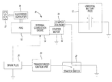
Providing low current to starter solenoid 34 turns on starter motor 32, thereby turning IC engine 14. Starter switch 20 is spring-loaded so that it returns to the ‘ON’ position upon successfully starting IC engine 14. In the ‘ON’ position starter switch 20 directs power from ignition unit 24 to spark plug 26. Each time spark plug 26 fires, spark is provided to IC engine 14, which is utilized to ignite a compressed fuel and air mixture present in a cylinder (not shown) during a compression cycle of IC engine 14. When IC engine 14 is running it turns alternator 36, which creates an output voltage usable to provide AC power at outlet 22.
When IC engine 14 is running it turns PMG 52, which creates a 3-phase output. The 3-phase output is converted by the electronic converter circuit 54 to usable AC power that is provided to outlet 22. The electronic converter circuit 54 can be any suitable inverter circuit, such as the inverter circuit described in patent application Ser. No. 10/077,219, filed Feb. 15, 2002, entitled Alternator/Inverter With Dual H-Bridge, herein incorporated by reference in its entirety.
In ‘Generator Mode’, PMG 52 provides a three phase AC output signal to a controlled full wave bridge rectifier circuit 122. Rectifier circuit 122 is coupled across DC bus lines, or rails, 128 and 134 that form a DC bus. Also coupled across the DC bus is a full H-bridge circuit 140 comprising four identical power switching devices 146 a-146 d. An inductor 152 and a capacitor 158 are coupled across nodes 164 and 170 and form an LC filter for attenuating harmonic distortion in the output waveform generated by the H-bridge 140. Each of the power switching devices 146 a-146 d may comprise a variety of suitable power switching components, for example field effect transistors (FET's) or insulated gate bi-polar transistors (IGBT's). A pair of DC bus capacitors 176 and 182 are also coupled in series across the DC bus rails 128 and 134. Although the DC bus capacitance is shown to only include the pair of capacitors 176 and 182, it is envisioned that the DC bus capacitance could comprise any even number of capacitors. One phase of second windings 52 b is connected at a center node between even numbers of the DC bus capacitors.
In starting operation, with 4-pole, double throw switch 194 de-energized, as shown, load 108 is disconnected and the three phases of second windings 52 b are connected to center nodes 164 and 170 of H-bridge 140 and a center node 224 of the DC bus capacitance. With key switches 206 and 212 turned to a ‘Start’ position, portable universal battery pack 12 is connected across DC bus rails 128 and 134 and power switching devices 146 a-146 d are sequenced to run PMG 52 in the ‘Motor Mode’. In this mode PMG 52 acts as a motor to turn IC engine 14. The power switching devices 146 a-146 d are sequenced by signals from a Hall effect position sensor (not shown) and coupled, via an AND gate (not shown), with a pulse width modulated (PWM) signal. Power switching devices 146 a-146 d create two phases of a three phase drive signal used to drive PMG 52 as a brushless DC motor with capacitors 176, 182 creating the third phase.
The PWM signal is based on the rated voltage output of universal battery pack 12. Thus, the rated voltage output of universal battery pack 12 need not conform to one predetermined DC voltage. The rated voltage output of universal battery pack 12 can be, for example, a voltage preferably of 12 volts or greater, preferably ranging from 12 to 18 volts. For example, a NiCd universal battery pack of 12, 14.4 or 18 volts can be utilized with circuit 100 and regardless of the output voltage, the effective voltage provided to PMG second windings 52 b will be approximately equal to that of a 12 volt battery.
When the DC bus voltage exceeds the initial voltage of universal battery pack 12, for example 20 volts or greater, relay coil 218 is energized to disconnect second windings 52 b from H-bridge circuit 140 and bus capacitors 176 and 182 and to connect load 108 to the output of H-bridge circuit 140. Once second windings 52 b are disconnected from H-bridge circuit 140, PMG 52 is switched to ‘Generator Mode’. In ‘Generator Mode’, PMG 52 outputs variable voltage, variable frequency AC power, via first windings 52 a. Full wave bridge rectifier circuit 122 and H-bridge circuit 140 convert the AC power to a constant voltage, constant frequency output, for example a 120 VAC, 60 Hz, that is output from H-bridge circuit 140 to load 108.
Utilizing universal battery pack 12 and PMG 52 to provide starting power to IC engine 14 greatly reduces the size and weight of generator system 90. It is envisioned that universal battery pack 12 can be any universal battery pack commonly used in many cordless power tools, for example the DEWALT XR PLUS (Extended Run Time Plus) line of batteries.
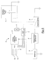
The 3-phase PMG 52 includes position sensors 320, 322 and 324, which are illustratively Hall effect sensors, that are connected to BLDC/PMG starter control 256 by lines 314, 316 and 318, respectively. Position sensors 320, 322, 324 sense the position of a rotor (not shown) of PMG 52. Additionally, DC drive circuit 250 includes a momentary starter switch 330 that controls the flow of current from universal battery pack 12 to BLDC/PMG starter control 256.
In operation, initially IC engine 14 is at rest. The IC engine 14 is started by a user closing momentary start switch 330. The BLDC/PMG starter control 256 will then become energized by universal battery pack 12. Provided the position sensors 320, 322 and 324 indicate that either the speed of IC engine 14 or the speed of PMG 52 is less than a predetermined value, e.g. 600 rpm, 3-pole relay switch 268 will be energized by BLDC/PMG starter control 256, thereby connecting the 3-phase power stage 262 to PMG 52. Utilizing information from position sensors 320, 322 and 324, the switching devices 274 a-274 f are turned on and off by BLDC/PMG starter control 256. The switching of switching devices 274 a-274 f electronically commutates second 3-phase windings 52 b within PMG 52 to drive PMG 52 as a brushless DC motor to rotate IC engine 14 to start it.
Thus, when PMG 52 is in ‘Motor Mode’, IC engine 14 will be turned by PMG 52 acting as a motor and will accelerate up to a speed to start IC engine 14. Once IC engine 14 has started, PMG 52 is driven past a predetermined maximum speed, e.g. 600 rpm, and 3-pole relay switch 268 will then be de-energized, thereby disconnecting power stage 262 from PMG 52. Disconnecting power stage 262 avoids overdriving universal battery pack 12 and supplying excessive voltage to switching devices 274 a-274 f. Once the starting operation is complete, momentary starter switch 330 is opened.
BLDC/PMG starter control 256 can be microprocessor based to simplify the electronic circuitry and to provide additional control features. Additional control features may include setting a maximum cranking time, e.g. 5 seconds, to avoid damage if momentary starter switch 330 is held closed for too long, or not attempting starting of IC engine 14 when universal battery pack 12 does not have sufficient voltage to turn or start IC engine 14. Further control features provided by a microprocessor based BLDC/PMG starter control 256 may include speed detection and control of 3-pole relay switch 268 to avoid overdriving universal battery pack 12 and power stage 262. Even further control features may include setting an upper starting speed of PMG 52 regardless of the voltage of universal battery pack 12 by utilizing pulse width modulation control of switching devices 274 a-274 f above a minimum speed.
In an alternate embodiment, PMG 52 includes a single set of tapped windings. In this embodiment, the first windings 52 a comprise the full windings, which are used to generate AC power in the ‘Generator Mode’. The second windings 52 b comprise the tapped portion of the windings, which are used to drive PMG 52 as a motor in the ‘Motor Mode’ to start the IC engine 14.
Although the present invention has been shown and described in connection with a portable generator using a single PMG and a single alternator/inverter circuit, or a single brushless DC drive circuit, the present invention could just as readily be adapted for use with starter systems of portable generators utilizing a pair of PMG's and a pair of alternator/inverter circuits. Alternatively, the present invention could be used with a portable generator using a pair of PMG's with a pair of brushless DC motor drive circuits, such as that described in patent application Ser. No. 10/077,386, filed Feb. 15, 2002, entitled Alternator/Inverter With Dual H-Bridge and Automatic Voltage Regulation, herein incorporated by reference in its entirety. The invention is further applicable to all types of small IC engines, for example a lawnmower engine. Thus, the scope of the invention should not be construed as being limited only to portable generators.
The present invention thus provides a means for starting an internal combustion engine utilizing a universal battery pack, wherein the universal batter pack is able to be used with other cordless power tools. Also, by controlling an H-Bridge switching circuit in a predetermined switching sequence, the H-Bridge can be used to control the application of power to a PMG to enable the PMG to be effectively used as a starter motor to start the internal combustion engine.
With reference to FIGS. 9-12 , battery receptacle 912 illustratively includes housing halves 914 mated together to form a housing 915. A collar 917, illustratively a rectangular shaped collar, surrounds housing 915 and includes screw posts 1200 (only one of which is shown in FIG. 12 ) for receiving screws which secure collar 917 to control panel 806. Housing 915 includes a base portion 919 having an outer plate 916 that conforms to an upper plate 1102 of battery pack 1100 (FIG. 11 ) and a columnar portion 1218 (FIG. 12 ) extending from base portion 919. Opposed flanges 1214 (FIG. 12 ) project outwardly from housing halves 914 at opposed edges of outer plate 916. Opposed flanges 1214 include slots 1216 therein that mate with inwardly extending projections 1300 (FIG. 13 ) of collar 917 to secure housing 915 to control panel 806 when collar 917 is secured to control panel 806.
Housing halves 914 include opposed channels 1210 that receive opposed flanges of connector 1202 to mount connector 1202 in housing 915.
By providing on control panel 806 a battery receptacle 912 that is essentially a foot of a cordless power tool, a user of generator 800 can advantageously use the battery pack for the cordless power tool, such as battery pack 1100, in starting generator 800. Illustratively, battery pack 1100 is not charged by generator 800. Rather, when battery pack 1100 needs charging, it is charged in an external charger, such as the external charger that is typically provided with the cordless power tool when the user purchases the cordless power tool.
By using a battery pack from a cordless power tool, such as battery pack 1100, generator 800 does not require its own battery, which is typically a lead acid type of battery. The user need not purchase the lead acid battery, avoids the need to maintain such a lead acid battery, and generator 800 is lighter since the weight of the lead acid battery is eliminated.
In use, a battery pack, such as battery pack 1100, from a cordless power tool is placed in battery receptacle 1412 and provides electrical power to start internal combustion engine 1404. Charger 1414 is used to charge one or more battery packs 1100. In this regard, once internal combustion engine 1404 is started, the battery pack 1100 in battery receptacle 1412 can be removed from battery receptacle 1412 and placed in charger 1414 to charge that battery pack 1100.
In an aspect of the invention, portable generator 800 is adapted to use universal battery packs having different voltages. More specifically with reference to FIG. 16 , portable generator 800 includes a voltage regulation circuit 1600 that couples connector 1202 of battery receptacle 912 to the starting device for internal combustion engine 804, thus coupling the output of battery pack 1100 to the starting device for internal combustion engine 804 when battery pack 1100 is received in battery receptacle 912. Voltage regulation circuit 1600 illustratively provides at its output 1602 a set voltage at the appropriate level for the starting device for internal combustion engine 804. For example, if the starting device for internal combustion engine 804 utilizes a 12 volt DC starter motor, then voltage regulation circuit 1600 provides 12 volts DC at its output 1602. Voltage regulation circuit 1600 may illustratively monitor the voltage at its output 1602 and adjust its output accordingly to maintain the appropriate voltage level.
With reference now to FIG. 17 , a simplified block diagram of a portable generator system 1610, according to additional features is shown. The generator system 1610 utilizes a battery pack 1612 that is mounted to generator system 1610 with fastening devices, such as one or more hold down members shown representatively by 1617. Hold down member(s) 1617 may be removably affixed to housing 1616 such as with screws (not shown). Battery pack 1612 is thus “permanently mounted” in housing 1616 in the sense that it is not easily removable by hand. But battery pack 1612 can be removed and replaced in the event of failure, such as by unfastening hold down member(s) 1617, removing and replacing back pack 1612, and refastening hold down member(s) 1617. Battery pack 1612 may comprise a battery pack such as the battery pack 1100 (FIG. 11 ). Further, battery pack 1612 may comprise any suitable battery pack such as a NiCad universal battery pack of 12, 14.4 or 18 volts. In this example however, the battery pack 1612 is permanently mounted within a housing 1616 mounted in a frame of generator system 1610, such as frame 1402 (FIG. 14 ). The housing 1616 may define similar components as described with respect to the enclosure 1406 (FIG. 14 ), but in this example, the housing 1616 surrounds the battery pack 1612. The housing 1616 may include any suitable containment structure. It is contemplated that the housing 1616 may provide a removable portion, such as a door or cover plate 1620 to gain access to the battery pack 1612 in the event the battery pack 1612 needs to be replaced. In one example, the cover plate 1620 may be removably secured to the housing 1616, such as by fasteners (not shown).
According to an additional feature of the generator system 1610 shown in FIG. 17 , a charging circuit 1630 may be provided. The charging circuit 1630 may be electrically connected to the power generating device 16 whereby the power generating device may provide the charging circuit with power to charge the battery pack 1612. It should be appreciated that while the charging circuit 1630 is specifically illustrated for use with the generator system 1610, it may easily be adapted for use in any of the generator systems disclosed herein. Charging circuit 1630 would illustratively be switched off during starting internal combustion engine 10 of generator system 1610 and then switched on after internal combustion engine 10 is started.
The generator system 1610 utilizes battery pack 1612 to start the IC engine 14 that turns the power generating device 16. The generator system 1610 may additionally include a starting device 18 connected to the battery pack 1612 and the starter switch. The starting device 18 may comprise any suitable starting device such as a starter motor and tarter solenoid (see e.g., FIG. 2 ). The starter switch 20 may be connected to the transistorized ignition unit 24, which is in turn connected to a the spark plug 26. The staring device 18 may be used to turn the IC engine 14 at a rate sufficient to start the IC engine 14. Once the IC engine 14 is started, the IC engine 14 drives power generating device 16. The power generating device 16 may output AC power usable by a load connected to the electrical outlet. Concurrently, the power generating device may provide power to the charging unit 1630 to charge the battery pack 1612. The power generator device may alternatively comprise a generator alternator (FIG. 2 ).
With reference now to FIG. 18 , a simplified block diagram of a portable generator system 1800, according to additional features is shown. The portable generator system 1800 includes an actuator switch 1802. The actuator switch 1802 is switchable to provide electrical connection between the universal battery pack 12 and the starting device 18 or between universal battery pack 12 and the charging circuit 1630. In this example, a user may place the universal battery pack 12 into the battery receptacle (such as battery receptacle 912, FIG. 9 ) and switch the actuator switch to a ‘Start’ position, thereby electrically coupling the universal battery pack 12 to the starting device 18. Once the actuator switch is in the ‘Start’ position, the starter switch 20 may also be placed into the ‘Start’ position such that the universal battery pack 12 provides power to the starting device 18 (such as a starter solenoid 34, FIG. 2 ). While the universal battery pack 12 has been shown, it is appreciated that alternatively, the permanently mounted battery pack 1612 in housing 1616 (FIG. 17 ) may be used.
Once the IC engine 14 is started, the spring loaded starter switch 20 may return to the ‘ON’ position. In the ‘ON’ position, the starter switch may direct power from the ignition unit 24 to the spark plug 26. Each time spark plug 26 fires, spark is provided to IC engine 14, which is utilized to ignite a compressed fuel and air mixture present in a cylinder (not shown) during a compression cycle of IC engine 14. When IC engine 14 is running it turns alternator 36, which creates an output voltage usable to provide AC power at outlet 22.
In addition, once the IC engine 14 has been started, the actuator switch 1662 may be moved to a ‘Charge’ position. In the ‘Charge’ position, the actuator switch 1662 may electrically connect the charging circuit 1630 to universal battery pack 12 to charge the universal battery pack 12. It is contemplated that the actuator switch 1662 may be spring-loaded so that it returns to the ‘Charge’ position upon successfully starting the IC engine 14. It is also contemplated that the operation of the actuator switch 1662 and the starter switch 20 may be combined into a single switch. In this way, a single start switch of the generator system 1660 may be wired such that charging is deactivated when the start switch is turned to the ‘Start’ position and then reactivates charging when the momentary start switch is released.
With reference now to FIGS. 19 and 20 , a portable generator 1700 having an enclosure 1706 is shown. The portable generator 1700 may include the frame 1402 that supports the IC engine 1404. The frame 1402 may illustratively support wheels 1401 (FIG. 8 ), and include handles 1403 for facilitating moving the generator 1700.
An electric generator device (hidden from view in FIG. 14 ) may be coupled to an output shaft of internal combustion engine 1404. The electric generator device generates AC power, such as has been described above. The AC power may illustratively be 120 VAC (or 110 or 115 VAC) and may also illustratively be 240 VAC (or 220 or 230 VAC). It may be 60 Hz, or may be 50 Hz. Generator 1700 may also include a control panel including AC outlets (not shown in FIG. 14 ).
The base portion 1408 of enclosure 1406 includes battery receptacle 1412, charger 1414 and AC outlet 1416. Battery receptacle 1412 is configured to receive a battery pack from a cordless power tool, such as battery pack 1100. In this regard, battery receptacle 1412 may be configured to receive a tower type of battery pack, such as battery pack 1100, as is charger 1414. As such, battery receptacle 1412 may illustratively have a configuration similar to battery receptacle 912 described above. Battery receptacle 1412 may alternatively be configured to receive a rail type of battery pack, such as battery pack 16 shown in U.S. Pat. No. 6,653,815, the disclosure of which is incorporated herein in its entirety by reference. As such, battery receptacle 1412 has a configuration similar to that on the foot of tool 10 of U.S. Pat. No. 6,653,815. That is, battery receptacle 1412 includes a pair of grooves that receives guide rails of the rail type battery pack. It also includes a connector configured to mate with the terminal block of the rail type battery pack.
With specific reference now to FIG. 20 , the hinged lid 1710 is shown in the closed position. As illustrated, the biasing members 1712 engage an upper surface of the battery packs 1100 and urge them downward into the receptacles 1412 and charger 1414. As a result, electrical connection of battery packs 1100 in receptacle 1412 and charger 1414 may be maintained during movement of the generator system 1700 such as by physical movement of the generator system 1700 as a whole or by vibratory movement communicated by the IC engine 14 during use. It is appreciated that the biasing members 1712 may additionally be provided on the housing 1616 disclosed for use with the permanent battery pack 1612 (FIG. 17 ).
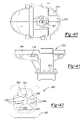
Turning now to FIGS. 21 and 22 , a pair of adapters 1750 and 1752 according to additional features of the present teachings are illustrated. The adapters 1750 and 1752 each have insertion portions 1760 and 1762, respectively for receipt into battery receptacles 912 (FIGS. 8-10 ) and/or 1412 (FIGS. 14 , 19 and 20). The adapter 1750 has a battery receptacle portion 1770 while the adapter 1752 has a battery receptacle portion 1772. Terminals 1776 may be located in the battery receptacle portion 1772 for electrical communication with a battery pack (not shown) received into the adapter 1752 in the battery receptacle portion 1772. As will be described, the adapters may be selectively inserted into any of the battery receptacles 912, and/or 1412 enabling battery receptacles 912 and or 1412 to accept battery packs having different footprints. In one aspect, these battery packs may be battery packs for use with power tools such as for different brands of power tools. Footprint as used with respect to a battery back relates to a battery receptacle portion 1772 of adapter 1752 means that part of the battery pack that is received in the battery receptacle portion 1772.
As can be appreciated, the respective battery receptacle portions 1770 and 1772 may define complementary geometry to accept battery packs having a footprint distinct from the tower 1104 of the DEWALT battery pack 1100 described in the examples above (FIG. 11 ). During use, a desired adapter 1750 or 1752 may be selectively inserted into battery receptacle 912, and/or 1412. One skilled in the art will appreciate that the insertion portions 1760 and 1762 mate with the receptacles 912 and/or 1412 similar to a battery pack 1100. Once the desired adapter has been inserted, a battery pack (not shown) having complementary mating structure with the battery receptacle portions 1770 or 1772 may be selectively inserted into the adapter 1750, 1752.
In one example, the additional height realized by using the adapter 1750, 1752 may be accommodated by the biasing member 1712. In another example, other biasing members and/or hinged lids 1710 may be provided to accommodate various geometry battery packs.
It is appreciated that other power driven apparatus may be adapted for use with the means for starting the internal combustion engine as disclosed herein.
With reference to FIG. 25 , an embodiment of control panel 806 in accordance with some embodiments of the present invention is illustrated. Control panel 806 includes top plate 2500 and housing 2502.
An exemplary embodiment of control panel 806 is illustrated in FIG. 26 . Housing 2502 has a depth sufficient to receive a battery pack, such as battery pack 1100, in battery receptacle 912. Housing 2502 provides an enclosure for charger assembly 2510, battery receptacle 912 and their associated connections (not shown in figures). Top panel 2500 and housing 2502 may be made of any suitable rigid material, e.g., stainless steel. Control panel housing 2502 further includes a plurality of fastener holes 2504 for mounting the control panel 806 to frame 802 of portable generator 800, as illustrated in FIG. 8 . Additional fastener holes 2504 may be utilized to secure top panel 2500 to housing 2502.
Referring now to FIGS. 27 and 28 , an exemplary embodiment of charger assembly 2510 is illustrated. Charger assembly 2510 is formed of base 2520 and cage 2530. Charger assembly base 2520 includes a wire collar 2522 and heat sink 2526 with associated plurality of fingers 2528. Base 2520 and cage 2530 are secured together with a plurality of fasteners 2515. Fasteners 2515 are inserted through fastener openings 2532 in cage 2530 and received in fastener receptacles 2524 of base 2520. Fasteners 2515 may comprise, for example, rivets, screws or other similar fastening devices. The use of fasteners 2515 fixedly secures the base 2520 with the cage 2530 of charger assembly 2510. A charger and associated charging circuitry (not shown) is received within charger assembly 2510, that is, substantially enclosed between base 2520 and cage 2530. Heat sink 2526 and plurality of fingers 2528 help secure the charger within charger assembly 2510, as well as provide protection to the charger itself. The cage 2530 of charger assembly 2510 may include a plurality of ribs 2536 arranged to define a plurality of cage vent openings 2534 to provide ventilation to the charger and its associated circuitry. Wire collar 2522 of base 2520 provides an opening for the wire of the charger to exit the charger assembly 2510. Furthermore, wire collar 2522 reduces the strain on the wire of the charger. The wire of the charger may be directly coupled to the output of the power generating device 16 or, alternatively, may exit the housing 2502 and end in a plug that can be inserted into AC outlets 902.
Illustratively, charger assembly 2510 is assembled as a complete unit and is then installed in control panel 806. This allows, by way of example and not of limitation, charger assembly 2510 to be a product supplied to the assembler of control panel 806.
Referring again to FIG. 26 , charger assembly 2510 installed in housing 2502 of control panel 806 is illustrated. Battery receptacle 912 is electrically connected to the charger and its associated circuitry within charger assembly 2510. As described above, for example as illustrated in FIGS. 17 and 18 , the electrical connections between battery pack 1100 and charging circuit 1630 may include an actuator switch 1802. The charger of charger assembly 2510 may comprise a stand alone charger (not shown) and/or charging circuit 1630, as illustrated in FIGS. 17 and 18 . Furthermore, battery pack 1100 as shown in control panel assembly 2500 may be replaced with permanent battery pack 1612, as illustrated in FIG. 17 .
Upon coupling top panel 2500 with control panel housing 2502, the sensitive circuitry and electrical connections of battery receptacle 912 and charger assembly 2510 are substantially enclosed. The control panel 806 provides protection to the charger and/or charging circuit 1630 and, in the case of permanently installed battery pack 1612, the battery pack from manipulation by the user, as well as moisture, dirt and other environmental conditions.
In various aspects of the present teachings, an indicating mechanism can be connected at one or more suitable locations on the battery pack 1100, so as to be detected by the battery receptacle 912 to indicate a predetermined battery chemistry associated with the cells in the battery pack 1100. In one example, the battery receptacle 912 can detect the indicating mechanism so as to determine the chemistry of the battery pack 1100 based on the detection. In this example, detection of the indicating mechanism can indicate the predetermined battery chemistry, e.g., a lithium ion (“Li-Ion”) battery chemistry. The inability to detect the indicating mechanism, in contrast, can indicate a different predetermined battery chemistry, e.g., a nickel cadmium (“Ni-Cad”) battery chemistry. It will be appreciated in light of the disclosure that detection of the indicating mechanism can be employed to detect (discern, etc.) between two battery chemistries, which can be selected from a group including, without limitation, nickel cadmium, nickel metal hydride, lithium ion, zinc-carbon, zinc-chloride, alkaline (zinc-manganese dioxide, lithium (lithium-copper oxide, lithium-iron disulfide and/or lithium-manganese dioxide), mercury oxide, zinc-air, silver oxide, etc. In an aspect, the indicating mechanism may be the indicating mechanism disclosed in International Patent Application No. PCT/US2008/007271 filed Jun. 11, 2008, the entire disclosure of which is incorporated herein by reference.
The battery receptacle 912 can also detect a data signal from a data connection (not shown) in the terminal block 1112 to further confirm the battery chemistry of the battery pack 1110. Specifically, detection of both the indicating mechanism and the data signal from the data connection can indicate the predetermined battery chemistry, e.g., a lithium ion (“Li-Ion”) battery chemistry. The inability to detect either the indicating mechanism or the data signal from the data connection, in contrast, can indicate a different predetermined battery chemistry, e.g., a nickel cadmium (“Ni-Cad”) battery chemistry.
In various embodiments, the indicating mechanism can be located in the terminal block 1112 and can be configured to be similar to the power terminals 1114, 1116 and/or the data connection. In one example, the indicating mechanism can be referred to as a fourth terminal. By way of the above example, the power terminals 1114, 1116 comprise the first and second terminals, and the data connection can comprise a third terminal, so that the indicating mechanism can be the fourth terminal.
In other examples, the terminal block 1112 can contain a fourth terminal used for purposes other than that described above, such that the indicating mechanism can be located at other locations on the battery pack 1110 and, in various instances, outside of the terminal block 1112. As such, the indicating mechanism can be referred to as a fifth terminal, or whatever terminal, connection, etc. may be applicable based on the configuration of the battery pack 1110. It will be appreciated that the indicating mechanism can be located at various locations on the battery packs regardless of whether the battery pack 1110 is provided with a rail configuration or the tower configuration illustrated in FIG. 11 .
With reference to FIG. 29 , one example of an indicating mechanism 1150 is shown associated with a battery pack 1152 and a battery receptacle 1154. The indicating mechanism 1150 can be configured so as to include a spring member 1156 that can extend from the battery receptacle 1154 and contact the battery pack 1152. The spring member 1156 can contact a connector 1158 on the battery pack 1152 so that, for example, a reference voltage can be detected by the battery receptacle 1154 and/or the battery pack 1152. Detecting the indicating mechanism 1150, therefore, can include detecting the reference voltage.
In a further example, the spring member 1156 can contact the connector 1158 on the battery pack 1152 so that, for example, continuity can be detected by the battery receptacle 1154 and the battery pack 1152. In this case, detecting the indicating mechanism 1150 can, therefore, include detecting continuity.
In other examples, the indicating mechanism 1150 can include a spring member 1156 that can extend from the battery receptacle 1154 and contact the battery pack 1152. In this example, the spring member 1156 can contact a portion of the battery pack 1152 so that, for example, deflection of the spring member 1156 can activate a switch (e.g., a micro switch) and/or one or more suitable mechanical or electromechanical devices. Detecting the indicating mechanism 1150 can, therefore, include detecting a signal from the switch activated by the indicating mechanism 1150.
With reference to FIG. 30 , an example of an indicating mechanism 1160 is shown associated with a battery pack 1162 and a battery receptacle 1164. The indicating mechanism 1160 can include a spring member 1166 that can extend from the battery pack 1162 and contact the battery receptacle 1164. Similar to the indicating mechanism 1150 in FIG. 29 , the spring member 1166 can contact a connector 1168 on the battery receptacle 1164 so that, for example, a reference voltage or continuity can be detected. In addition, the spring member 1166 can activate a switch as explained above.
With reference to FIG. 31 , one example of an indicating mechanism 1170 is shown associated with a battery pack 1172 and a battery receptacle 1174. The indicating mechanism 1170 can include an emitter 1176 and a receiver 1178. In general, detecting the indicating mechanism 1170 can, therefore, include detection of one or more electromagnetic wave signals 1180 from the emitter 1176 by the receiver 1178. In one instance, the emitter 1176 can be one or more members that can produce a magnetic field (e.g., a magnet, an electromagnet, etc.). The receiver 1178 can be a hall-effect sensor. Detection of the indicating mechanism 1170 can, therefore, include the hall-effect sensor detecting the one or more members that produce the magnetic field. In a further example, the emitter 1176 can emit a radio frequency (RF) signal that can be received (i.e., detected) by the receiver 1178. In this instance, detection of the indicating mechanism 1170 can, therefore, include the receiver 1178 detecting the RF signal from the emitter 1176. It will be appreciated in light of the disclosure that the emitter 1176 can be located in or on the battery pack 1172 and the receiver 1178 can be located in or on the battery receptacle 1174 or vice versa, as applicable.
With reference to FIGS. 32 through 39 , various positions of an indicating mechanism can be shown on a battery pack having a tower configuration. It will be appreciated in light of the disclosure that similar locations, as applicable, can be implemented on a battery pack having a rail configuration such as those configured to be used with adaptor 1750 illustrated in FIG. 21 . With reference to FIG. 32 , a battery pack 2200 can include an indicating mechanism 2202. The indicating mechanism 2202 can be in a position that is relatively close to a terminal block 2204 that can contain a data connection and/or a communication connection (not shown). In this example, the indicating mechanism 2202 can be located on a tower portion 2206 outside of the terminal block 2204.
With reference to FIG. 33 , a battery pack 2220 can include an indicating mechanism 2222 that can be located on an upper deck 2224 of a body portion 2226 of the battery pack 2220. It will be appreciated in light of the disclosure that the positioning of the indicating mechanism 2222, in the example illustrated in FIG. 33 , can be at a greater distance from a terminal block 2228 than the indicating mechanism 2202 relative to the terminal block 2204, as illustrated in FIG. 32 .
It will be appreciated in light of the disclosure that other examples of placement of the indicating mechanism on the battery pack, examples of which are illustrated throughout FIGS. 32-39 , can include locations of the indicating mechanism that can maximize a distance between a terminal block and the indicating mechanism. The distance between the terminal block and the indicating mechanism can be maximized for various reasons. One reason can be shown to include avoiding obstructing the power connection, the data connection and the indicating mechanisms with, for example, a paint spill or other debris from the work site. By maximizing the distance between the data connection (and/or the power connection) and the indicating mechanism, it can be shown that the propensity somehow obstruct, cover, deactivate, etc. both the data connection and the indicating mechanism so as to not detect the data connection and/or the indicating mechanism as a proxy for a predetermined battery chemistry can be reduced.
With reference to FIG. 34 , a battery pack 2240 can include an indicating mechanism 2242 that can be positioned on a lower deck 2244 of the battery pack 2240. FIG. 35 illustrates an example of an indicating mechanism 2250 being on a side area 2252 of a battery pack 2254. While the indicating mechanism 2250 is illustrated on the side area 2252 of a base portion 2256, it will be appreciated in light of the disclosure that the indicating mechanism 2250 can be on a side of a tower portion 2258 in lieu of the base portion 2256.
With reference to FIG. 36 , a battery pack 2260 can include an indicating mechanism 2262 being on a side area 2264 of the battery pack 2260. While the indicating mechanism 2262 is illustrated on the side area 2264 of a tower portion 2266, it will be appreciated in light of the disclosure that the indicating mechanism 2262 can be on the side area 2264 of a base portion 2268 in lieu of the tower portion 2266. Moreover, the side area 2264 of the tower portion 2266 on which the indicating mechanism 2262 is located can be opposite the surface relative to the location of the indicating mechanism 2202 on the battery pack 2200, as illustrated in FIG. 32 .
With reference to FIG. 37 , a battery pack 2270 can include an indicating mechanism 2272 that can be located on a front area 2274 of the battery pack 2270. While the indicating mechanism 2272 is illustrated on the front area 2274 of a base portion 2276, it will be appreciated that the indicating mechanism 2272 can be on the front area 2274 of a tower portion 2278 in lieu of the base portion 2276. In FIG. 38 , a battery pack 2280 can include an indicating mechanism 2282 being on a rear area 2284 of the battery pack 2280. While the indicating mechanism 2282 is illustrated on the rear area 2284 of a tower portion 2286, it will be appreciated that the indicating mechanism 2282 can be on a rear area 2284 of a base portion 2288, in lieu of the tower portion 2286.
With reference to FIG. 39 , a battery pack 2290 can include an indicating mechanism 2292 that can be located on a side area 2294 of the battery pack 2290 having an enlarged tower portion 2296 The enlarged tower portion 2296 can sometimes be referred to as a two-up or a two tower configuration. While the indicating mechanism 2292 is illustrated on the side area 2294 of one tower portion 2296, it will be appreciated in light of the disclosure that the indicating mechanism 2292 can be on various areas of the battery pack 2290 including, but not limited to, the locations provided in the above examples.
Referring now to FIGS. 40-43 , a housing 3915 for use in conjunction with battery receptacle 912 (FIG. 9 ) according to various embodiments of the present disclosure is illustrated. Housing 3915 comprises two housing halves 3914 and terminal slot part 3920. Similar to the housing 915 illustrated in FIGS. 12 and 13 , housing 3915 is adapted to mate with a battery pack of a tower configuration, such as battery pack 1100 illustrated in FIG. 11 . Housing halves 3914 are adapted to mate together with terminal slot part 3920 to form housing 3915, as shown in FIG. 40 . Housing 3915 is affixed to mounting plate 3916 (FIG. 43 ) which mounts to control panel 806.
With reference to FIG. 41 , a magnetic sensor 4100, such as a Hall effect sensor, is received in housing 3915. When battery pack 912 is a Li-Ion battery pack, a magnet in battery pack 912 will align with magnetic sensor 4100 when battery pack 912 is received in housing 3915.
With reference to FIG. 43 , a terminal board 4302 is affixed to a bottom 4300 of housing 3915. With reference to FIG. 44 , terminal board 4302 includes terminals that extend into terminal slots 3925 including positive terminal 4400, negative terminal 4402, and third terminal 4404. A negative temperature coefficient sensor 4406 is affixed to negative terminal 4402. Illustratively, when battery pack 912 is a NiCad battery pack, third terminal 4404 connects to a temperature sensor in the NiCad battery pack. Illustratively, when battery pack 912 is a Li-Ion battery pack, third terminal 4404 provides a data terminal and in conjunction with magnetic sensor 4100, is used to verify that the battery pack 912 is a Li-Ion battery pack.
Referring now to FIGS. 45 and 46 , housing half 3914 is illustrated with partially inserted exemplary battery pack 4500. Battery pack 4500 includes terminals 4502 and keying features 4504 for mating with terminal slot part 3920. As described above, the terminal slot part 3920 includes terminal protrusion 3924 and keying features 3922 that mate with the terminals 4502 and keying features 4504 of battery pack 4500 when the battery pack is received within the housing. FIG. 46 shows a battery receptacle housing half 3914 with battery pack 4500 completely inserted within housing half 3914 and terminal slot part 3920. The battery pack 4500 is inserted within terminal slot part 3920 such that the terminals 4502 mate with a terminal board 4302.
Referring now to FIG. 47 , a magnetic sensor 4100, such as a Hall effect sensor, may be present in the housing 3915. Magnetic sensor 4100 will detect the presence of a magnet 4510 in the battery pack 4500 when it is inserted into the housing 3915. The magnetic sensor 4100 is coupled to the electronics of the portable generator through wires 4102 in the illustrated examples, however, other means of communication (e.g., wireless communication) may be employed. Wires 4102 may be integrated within the housing 3915 or otherwise anchored in fixed relation to housing 3915.
Those skilled in the art can now appreciate from the foregoing description that the broad teachings of the present invention can be implemented in a variety of forms. Therefore, while this invention has been described in connection with particular examples thereof, the true scope of the invention should not be so limited since other modifications will become apparent to the skilled practitioner upon a study of the drawings, specification and following claims.
Claims (22)
1. A portable electrical generator system, comprising:
a manually movable frame supporting an internal combustion engine that drives a generator device supported on the frame that generates AC power, the internal combustion engine coupled to the generator device;
a starting device coupled to the internal combustion engine; and
a control panel assembly coupled to the frame, comprising:
a control panel having at least one AC outlet coupled to the generator device;
a housing having a battery receptacle therein electrically coupled to the starting device, the battery receptacle configured to receive a cordless power tool battery pack, the battery pack received in the battery receptacle and providing electrical power to the starting device;
a charger assembly including a charger electrically coupled between the battery pack received in the receptacle and the generator device when the internal combustion engine is running to charge the battery pack and electrically decoupled from the battery pack when the internal combustion engine is being started; and
the charger assembly including a base portion coupled to a cage portion, the charger received on the base portion.
2. The system of claim 1 , wherein the charger is substantially enclosed by the base portion and the cage portion.
3. The system of claim 2 , wherein the cage portion comprises a plurality of ribs arranged to define vents in the cage portion.
4. The system of claim 1 , wherein the charger assembly is coupled to the housing of the control panel assembly.
5. The system of claim 1 , wherein the charger assembly further comprises a wire collar adapted to support a wire connection from the charger.
6. The system of claim 5 , wherein the wire connection comprises a wire extending from the charger, passing through the wire collar and terminating with a plug.
7. The system of claim 6 , wherein the plug is insertable into the at least one AC outlet.
8. The system of claim 7 , wherein the battery pack is charged when the internal combustion engine is running and the plug is inserted into the at least one AC outlet.
9. The system of claim 5 , wherein the wire connection extends through the housing.
10. The system of claim 1 , wherein the charger comprises a stand alone charger that is substantially enclosed within the base and cage portions.
11. The system of claim 10 , wherein the stand alone charger comprises a wire extending from the base and cage portions and terminating with a plug.
12. The system of claim 11 , wherein the plug is insertable into the at least one AC outlet.
13. The system of claim 12 , wherein the battery pack is charged when the internal combustion engine is running and the plug is inserted into the at least one AC outlet.
14. The system of claim 1 , wherein the battery receptacle receives a battery pack that is one of a plurality of battery packs having different voltages, the system including a voltage regulation circuit coupling the battery receptacle to the starting device, the voltage regulation circuit providing at an output coupled to the starting device a voltage at a desired level for the starting device regardless of the voltage of the battery pack received in the battery receptacle.
15. A portable electrical generator system, comprising:
a manually movable frame supporting an internal combustion engine that drives a generator device supported on the frame that generates AC power, the internal combustion engine coupled to the generator device;
a starting device coupled to the internal combustion engine; and
a control panel assembly coupled to the frame, comprising:
a control panel having at least one AC outlet coupled to the generator device;
a housing having a battery receptacle therein electrically coupled to the starting device, the battery receptacle adapted to receive a cordless power tool battery pack for providing electrical power to the starting device when the battery pack is received in the battery receptacle; and
a charger assembly substantially enclosed within the control panel and the housing, comprising:
a stand alone charger electrically coupled between the battery pack received in the receptacle and the generator device when the internal combustion engine is running to charge the battery pack and electrically decoupled from the battery pack when the internal combustion engine is being started; and
a base portion coupled to a cage portion, the stand alone charger received on the base portion and substantially enclosed by the base portion and cage portion.
16. The system of claim 15 , wherein the battery receptacle comprises a keying feature configured to mate with a complementary key of the cordless tool battery pack when the cordless tool battery pack is properly inserted in the battery receptacle.
17. The system of claim 16 , wherein the keying feature is configured to inhibit insertion of the cordless tool battery pack when incorrectly inserted in the battery receptacle.
18. The system of claim 16 , wherein the keying feature is configured to indicate a battery chemistry of the cordless tool battery pack when inserted in the battery receptacle.
19. The system of claim 16 , wherein the battery receptacle is configured to determine a battery chemistry of the cordless tool battery pack by sensing an indicator mechanism on the cordless tool battery pack.
20. The system of claim 15 , wherein the battery receptacle is configured to determine a battery chemistry of the cordless tool battery pack by sensing an indicator mechanism on the cordless tool battery pack.
21. The system of claim 15 , wherein the stand alone charger is plugged into the at least one AC outlet.
22. The system of claim 15 , wherein the stand alone charger is electrically coupled to the generator device by hard wiring.
Priority Applications (3)
| Application Number | Priority Date | Filing Date | Title |
|---|---|---|---|
| US12/508,109 US8319357B2 (en) | 2002-06-06 | 2009-07-23 | Starter system for portable internal combustion engine electric generators using a portable universal battery pack |
| CA2709375A CA2709375C (en) | 2009-07-23 | 2010-07-08 | Starter system for portable internal combustion engine electric generators using a portable universal battery pack |
| EP10170046.6A EP2295790A3 (en) | 2009-07-23 | 2010-07-19 | Starter system for portable internal combustion engine electric generators using a portable universal battery pack |
Applications Claiming Priority (5)
| Application Number | Priority Date | Filing Date | Title |
|---|---|---|---|
| US38690402P | 2002-06-06 | 2002-06-06 | |
| US10/453,988 US7180200B2 (en) | 2002-06-06 | 2003-06-04 | Starter system for portable internal combustion engine electric generators using a portable universal battery pack |
| US11/321,773 US7309928B2 (en) | 2002-06-06 | 2005-12-29 | Starter system for portable internal combustion engine electric generators using a portable universal battery pack |
| US11/526,825 US7687926B2 (en) | 2002-06-06 | 2006-09-25 | Starter system for portable internal combustion engine electric generators using a portable universal battery pack |
| US12/508,109 US8319357B2 (en) | 2002-06-06 | 2009-07-23 | Starter system for portable internal combustion engine electric generators using a portable universal battery pack |
Related Parent Applications (1)
| Application Number | Title | Priority Date | Filing Date |
|---|---|---|---|
| US11/526,825 Continuation-In-Part US7687926B2 (en) | 2002-06-06 | 2006-09-25 | Starter system for portable internal combustion engine electric generators using a portable universal battery pack |
Publications (2)
| Publication Number | Publication Date |
|---|---|
| US20090295169A1 US20090295169A1 (en) | 2009-12-03 |
| US8319357B2 true US8319357B2 (en) | 2012-11-27 |
Family
ID=42938263
Family Applications (1)
| Application Number | Title | Priority Date | Filing Date |
|---|---|---|---|
| US12/508,109 Active 2025-01-17 US8319357B2 (en) | 2002-06-06 | 2009-07-23 | Starter system for portable internal combustion engine electric generators using a portable universal battery pack |
Country Status (3)
| Country | Link |
|---|---|
| US (1) | US8319357B2 (en) |
| EP (1) | EP2295790A3 (en) |
| CA (1) | CA2709375C (en) |
Cited By (11)
| Publication number | Priority date | Publication date | Assignee | Title |
|---|---|---|---|---|
| US8864476B2 (en) * | 2011-08-31 | 2014-10-21 | Flow Control Llc. | Portable battery operated bilge pump |
| US20150241085A1 (en) * | 2014-02-27 | 2015-08-27 | Charles Robert Justus | Energy supply module and method of assembling the same |
| US9624891B2 (en) | 2014-02-21 | 2017-04-18 | Briggs & Stratton Corporation | Outdoor power equipment incorporating starter battery with integrated push button |
| US9726135B2 (en) | 2014-02-21 | 2017-08-08 | Briggs & Stratton Corporation | Snowthrower with removable self-heating starter battery pack |
| US20180009431A1 (en) * | 2016-07-08 | 2018-01-11 | Toyota Jidosha Kabushiki Kaisha | Vehicle and control method therefor |
| US20180045160A1 (en) * | 2014-10-29 | 2018-02-15 | Mitsubishi Heavy Industries, Ltd. | Engine, self-starter unit, and method for altering engine specifications |
| US20180287460A1 (en) * | 2017-03-30 | 2018-10-04 | Honda Motor Co., Ltd. | Engine generator |
| US11105279B2 (en) * | 2017-02-17 | 2021-08-31 | Briggs & Stratton, Llc | On-demand generator starting system |
| US11245280B2 (en) | 2018-08-21 | 2022-02-08 | Milwaukee Electric Tool Corporation | Vehicle battery jump starter powered by a removable and rechargeable battery pack |
| US11374429B2 (en) | 2020-05-07 | 2022-06-28 | Milwaukee Electric Tool Corporation | Vehicle battery jump starter with multiple battery pack compatibility |
| US11973366B2 (en) | 2020-10-20 | 2024-04-30 | Schumacher Electric Corporation | Battery booster |
Families Citing this family (18)
| Publication number | Priority date | Publication date | Assignee | Title |
|---|---|---|---|---|
| KR101180956B1 (en) * | 2010-12-02 | 2012-09-07 | 기아자동차주식회사 | Antitheft system of charger for electric vehicle |
| US20130051104A1 (en) * | 2011-08-23 | 2013-02-28 | Hitachi Koki Co., Ltd. | Battery Adapter and Power Source Device Employing Same |
| DE102011053028A1 (en) * | 2011-08-26 | 2013-02-28 | Krauss-Maffei Wegmann Gmbh & Co. Kg | Vehicle start assist unit, vehicle and method for operating a vehicle jump starting unit |
| US9127658B2 (en) * | 2011-11-04 | 2015-09-08 | Briggs & Stratton Corporation | Internal combustion engine including starting system powered by lithium-ion battery |
| US8857138B2 (en) | 2011-11-04 | 2014-10-14 | Briggs & Stratton Corporation | Starter system for an engine |
| US8733072B2 (en) | 2011-11-04 | 2014-05-27 | Briggs & Stratton Corporation | Starter system for an engine |
| US9347837B2 (en) * | 2012-04-17 | 2016-05-24 | Honeywell International Inc. | Multi-phase brushless DC motor control integrated circuit having magnetic sensor and band-gap temperature sensor formed thereon |
| EP2838336B1 (en) * | 2012-04-17 | 2017-10-04 | Briggs & Stratton Corporation | Starter system for an engine |
| US20140370743A1 (en) * | 2013-06-13 | 2014-12-18 | Jim Maesnor | External Power Supply |
| PL2844865T3 (en) * | 2013-06-20 | 2016-11-30 | Internal combustion engine including electric starting system powered by lithium-ion battery | |
| US10044197B2 (en) | 2013-12-12 | 2018-08-07 | Milwaukee Electric Tool Corporation | Portable power supply and battery charger |
| US11444464B1 (en) * | 2016-03-25 | 2022-09-13 | Goal Zero Llc | Portable hybrid generator |
| US10255787B1 (en) * | 2017-03-10 | 2019-04-09 | Alarm.Com Incorporated | Magnetic sensor batteries |
| CN110086390B (en) * | 2018-01-25 | 2021-03-30 | 重庆和亚科技有限公司 | Power generation equipment for providing double-level voltage and movable generator set |
| CN110086389B (en) * | 2018-01-25 | 2021-03-30 | 重庆和亚科技有限公司 | Power generation equipment and movable generator set running off grid |
| CA3133573A1 (en) * | 2019-03-14 | 2020-09-17 | Potencia Industrial, Llc | Power supply system and system for providing start-up of engines used in such power supply system |
| CN213980949U (en) * | 2020-08-27 | 2021-08-17 | 康明斯电力公司 | System for generator set |
| US20220376526A1 (en) * | 2021-05-24 | 2022-11-24 | Kohler Co. | Hybrid generator with detachable power unit and panel integration |
Citations (120)
| Publication number | Priority date | Publication date | Assignee | Title |
|---|---|---|---|---|
| US1705673A (en) | 1924-01-22 | 1929-03-19 | Westinghouse Electric & Mfg Co | Battery-charging system |
| US2314687A (en) | 1942-06-08 | 1943-03-23 | Gen Motors Corp | Battery charging system |
| US2444460A (en) | 1946-02-05 | 1948-07-06 | Us Sec War | Remote-control system |
| US2526671A (en) | 1946-07-25 | 1950-10-24 | Kober William | Voltage compensator |
| US3217224A (en) | 1962-12-03 | 1965-11-09 | George W Sherwood | Flashlight battery charging equipment |
| US3366869A (en) | 1964-11-19 | 1968-01-30 | Gen Motors Corp | Induction type generator control circuit |
| US3444460A (en) | 1966-11-30 | 1969-05-13 | United Aircraft Corp | Electrodeless radio frequency conductivity probe and circuits therefor |
| US3456119A (en) | 1966-08-17 | 1969-07-15 | Modern Ind Inc | Vehicular remote power unit |
| US3518445A (en) | 1967-08-07 | 1970-06-30 | Ralph D Wichman | Automatic starting control for engine-generator |
| US3660671A (en) | 1970-07-20 | 1972-05-02 | Edwin R Peterson | Electric power takeoff system |
| US3671851A (en) | 1970-09-09 | 1972-06-20 | Briggs & Stratton Corp | Electrical system for tractor powered by magneto ignition engine |
| US3908161A (en) | 1974-02-07 | 1975-09-23 | Gen Electric | Field excitation system for synchronous machines utilizing a rotating transformer brushless exciter generating combination |
| US4122354A (en) | 1977-04-06 | 1978-10-24 | Thermo King Corporation | Internal combustion engine starting circuit |
| US4181929A (en) | 1977-01-06 | 1980-01-01 | Venture Ride Mfg. Inc. | Portable illuminating tower |
| USRE31216E (en) | 1975-06-19 | 1983-04-19 | Central Welding Supply Co., Inc. | Controller for DC arc welding generators |
| US4743777A (en) | 1986-03-07 | 1988-05-10 | Westinghouse Electric Corp. | Starter generator system with two stator exciter windings |
| US4772802A (en) | 1987-08-19 | 1988-09-20 | Sundstrand Corporation | Starting/generating system |
| US4786852A (en) | 1986-07-18 | 1988-11-22 | Sundstrand Corporation | Inverter operated turbine engine starting system |
| US4830412A (en) | 1987-10-26 | 1989-05-16 | Sundstrand Corporation | Starting system and method using a hybrid permanent magnet/induction machine |
| US4862551A (en) | 1989-02-28 | 1989-09-05 | Martinez Donald L | Self-contained cleaning system |
| US4883973A (en) | 1988-08-01 | 1989-11-28 | General Motors Corporation | Automotive electrical system having a starter/generator induction machine |
| US4907546A (en) | 1987-12-02 | 1990-03-13 | Kubota Ltd. | Air-cooled type cooling system for engine working machine assembly |
| US4947100A (en) | 1989-10-16 | 1990-08-07 | Sundstrand Corporation | Power conversion system with stepped waveform inverter having prime mover start capability |
| US4965477A (en) | 1989-03-17 | 1990-10-23 | Sundstrand Corporation | Integrated drive generator with permanent magnet generator on second shaft |
| US4988584A (en) | 1989-10-02 | 1991-01-29 | Quantum Instruments, Inc. | Lockable power module and method, particularly for electronic flash units |
| US5012177A (en) | 1989-12-19 | 1991-04-30 | Sundstrand Corporation | Power conversion system using a switched reluctance motor/generator |
| US5013929A (en) | 1989-11-22 | 1991-05-07 | Sundstrand Corporation | Power conversion system having prime mover start capability |
| US5038095A (en) | 1989-12-05 | 1991-08-06 | Sundstrand Corporation | Control for a DC link power conversion system |
| US5065086A (en) | 1988-04-19 | 1991-11-12 | Shinko Electric Co., Ltd. | Engine driven generator |
| US5091679A (en) | 1990-06-20 | 1992-02-25 | General Motors Corporation | Active vehicle suspension with brushless dynamoelectric actuator |
| US5111127A (en) | 1990-06-25 | 1992-05-05 | Woodward Johnson | Portable power supply |
| US5132604A (en) | 1989-04-04 | 1992-07-21 | Honda Giken Kogyo Kabushiki Kaisha | Engine starter and electric generator system |
| US5144217A (en) | 1989-03-03 | 1992-09-01 | Black & Decker Inc. | Cordless tool battery housing and charging system |
| US5159259A (en) | 1991-07-15 | 1992-10-27 | American Signal Company | Power supply system for continuously energizing a D.C. load |
| US5162662A (en) | 1989-09-22 | 1992-11-10 | Yamaha Hatsudoki Kabushiki Kaisha | Compact power supply with gas engine |
| US5166596A (en) | 1991-08-29 | 1992-11-24 | Motorola, Inc. | Battery charger having variable-magnitude charging current source |
| US5175439A (en) | 1987-12-21 | 1992-12-29 | Robert Bosch Gmbh | Power supply circuit for motor vehicles |
| US5208525A (en) | 1988-12-10 | 1993-05-04 | Gardena Kress + Kastner Gmbh | Electric power supply assembly for a cordless electric appliance |
| US5212952A (en) | 1988-07-09 | 1993-05-25 | Yamaha Hatsudoki Kabushiki Kaisha | Compact power supply and lubricant affording device therefor |
| US5325042A (en) | 1993-01-29 | 1994-06-28 | Allied Signal Inc. | Turbine engine start system with improved starting characteristics |
| US5341644A (en) | 1990-04-09 | 1994-08-30 | Bill Nelson | Power plant for generation of electrical power and pneumatic pressure |
| US5383605A (en) | 1992-12-10 | 1995-01-24 | Hydro-Chem Systems, Inc. | Radio controlled spraying device |
| US5533671A (en) | 1993-08-03 | 1996-07-09 | Unique Industries, Inc. | High pressure hot water chemical washer |
| US5548471A (en) | 1994-07-25 | 1996-08-20 | Webster Heating And Specialty Products, Inc. | Circuit and method for spark-igniting fuel |
| US5561330A (en) | 1994-12-27 | 1996-10-01 | Crook; Gaines M. | Automatic electric power generator control |
| US5570001A (en) | 1994-09-26 | 1996-10-29 | J.L. Behmer Corporation | Hand portable battery charger |
| US5629602A (en) | 1993-10-06 | 1997-05-13 | Ricoh Company, Ltd. | Portable electronic equipment with attachment for supplying power and charging battery |
| US5663011A (en) | 1994-08-11 | 1997-09-02 | Black & Decker Inc. | Battery pack retaining latch for cordless device |
| US5689174A (en) | 1993-08-13 | 1997-11-18 | Pacheco, Sr.; Angel Luis | Electrical power system |
| US5745043A (en) | 1996-10-15 | 1998-04-28 | Clarke Industries, Inc. | Indicator junction module for pressure washer |
| US5751070A (en) | 1995-04-26 | 1998-05-12 | Nippondenso Co., Ltd. | Combined starter and generator apparatus |
| US5787693A (en) | 1994-10-28 | 1998-08-04 | Black & Decker Inc. | Universal, retrofittable powerhead for small gasoline engine power implements |
| US5794580A (en) | 1997-02-26 | 1998-08-18 | Remote Products Inc. | Remote start/stop system for magneto ignition engines |
| US5861604A (en) | 1997-03-24 | 1999-01-19 | Generac Corporation | Arc welder and method providing use-enhancing features |
| US5902094A (en) | 1997-01-09 | 1999-05-11 | Generac Portable Products, Llc | Flow control valve for a pressure washer |
| US5920161A (en) | 1997-05-26 | 1999-07-06 | Hitachi, Ltd. | Driving system for permanent magnet type synchronous machine suitable for electric vehicle and driving control method using the same |
| US5929537A (en) | 1997-06-30 | 1999-07-27 | Sundstrand Corporation | PMG main engine starter/generator system |
| DE29821825U1 (en) | 1998-12-09 | 1999-08-12 | Detterbeck Stefan | Device for starting internal combustion engines and charging a starter battery |
| US5954494A (en) | 1993-08-19 | 1999-09-21 | Mi-T-M Corporation | Pressure washer blower ignition electrical system |
| US5986340A (en) | 1996-05-02 | 1999-11-16 | National Semiconductor Corporation | Ball grid array package with enhanced thermal and electrical characteristics and electronic device incorporating same |
| US5998976A (en) | 1996-11-08 | 1999-12-07 | Robert Bosch Gmbh | Power supply system |
| US6000370A (en) | 1997-11-20 | 1999-12-14 | Ryobi North America, Inc. | Compression release mechanism for an internal combustion engine |
| US6007373A (en) | 1998-05-22 | 1999-12-28 | Chew; William E. | Apparatuses and methods for coupling DC power tools to external DC power sources |
| US6008545A (en) | 1997-10-22 | 1999-12-28 | Toyota Jidosha Kabushiki Kaisha | Engine starting and electricity generating apparatus including 3-elements type input and output mechanism coaxial with motor/generator |
| US6034511A (en) | 1994-09-14 | 2000-03-07 | Coleman Powermate, Inc. | Light weight rotor and stator with multiple coil windings in thermal contact |
| US6075459A (en) | 1998-06-01 | 2000-06-13 | Saarem; Myrl J. | Remote starter for a combustion engine/electric generator set |
| US6075341A (en) | 1999-02-17 | 2000-06-13 | Black & Decker Inc. | Power pack charging system for a power tool |
| US6084313A (en) | 1998-08-13 | 2000-07-04 | Coleman Powermate, Inc. | Generator system with vertically shafted engine |
| US6100599A (en) | 1998-01-19 | 2000-08-08 | Honda Giken Kogyo Kabushiki Kaisha | Portable generator |
| US6118186A (en) | 1994-09-14 | 2000-09-12 | Coleman Powermate, Inc. | Throttle control for small engines and other applications |
| US6137251A (en) | 1998-07-31 | 2000-10-24 | S/L Montivideo Technology, Inc. | Brushless DC motor controller with speed control from zero to above based speed |
| US6140797A (en) | 1998-10-08 | 2000-10-31 | Dunn; James P. | Compact improved autonomous auxiliary engine starting apparatus |
| US6160373A (en) | 1998-08-10 | 2000-12-12 | Dunn; James P. | Battery operated cableless external starting device and methods |
| EP1060800A2 (en) | 1999-06-10 | 2000-12-20 | Lavorwash S.r.l. | Control device for high-pressure washers or the like |
| US6166525A (en) | 1998-01-26 | 2000-12-26 | Crook; Gaines M. | Automatic electric power generator control |
| US6191552B1 (en) | 1999-01-25 | 2001-02-20 | Dell Usa, L.P. | External universal battery charging apparatus and method |
| US6200277B1 (en) | 1997-08-28 | 2001-03-13 | Visco Technologies, Inc. | In-vivo apparatus and methods of use for determining the effects of materials, conditions, activities, and lifestyles on blood parameters |
| US6202776B1 (en) | 1995-08-31 | 2001-03-20 | Isad Electronic Systems Gmbh & Co. Kg | Drive system, especially for a motor vehicle, and method of operating same |
| US6260578B1 (en) | 1999-08-12 | 2001-07-17 | Delphi Technologies, Inc. | Spud assembly for a fuel tank |
| US6265091B1 (en) | 1997-06-06 | 2001-07-24 | Johnson Controls Technology Company | Modular electric storage battery |
| US6265786B1 (en) | 1998-01-05 | 2001-07-24 | Capstone Turbine Corporation | Turbogenerator power control system |
| EP1138938A2 (en) | 2000-03-31 | 2001-10-04 | Visteon Global Technologies, Inc. | Vehicle charge assembly |
| US6308059B1 (en) | 1997-12-12 | 2001-10-23 | Joseph Domes | Ruggedized tradesworkers radio |
| US20010043052A1 (en) | 2000-05-17 | 2001-11-22 | Griffey Tammy M. | Apparatus and method for providing a mobile AC power supply |
| US6326101B1 (en) | 1999-07-15 | 2001-12-04 | Black & Decker Inc. | Battery pack |
| US6380719B2 (en) | 1998-08-26 | 2002-04-30 | Satcon Technology Corporation | Integrated control system and method for controlling mode, synchronization, power factor, and utility outage ride-through for micropower generation systems |
| US6392312B1 (en) | 1999-10-26 | 2002-05-21 | Gary Jay Morris | Portable electric power generator with remote control and safety apparatus |
| US20020125857A1 (en) | 2001-03-09 | 2002-09-12 | Thomas Mastaler | Battery adapter for a cordless power tool system and related method |
| US6525511B2 (en) | 2000-08-11 | 2003-02-25 | Milwaukee Electric Tool Corporation | Adapter for a power tool battery |
| US20030117107A1 (en) | 2001-11-09 | 2003-06-26 | Zick Jonathan A. | Electrical component, such as a radio, audio component, battery charger or radio/charger |
| US6599072B1 (en) | 1998-11-13 | 2003-07-29 | TOGE-Dübel A. Gerhard KG | Corrosion resisting screw with cutting insert |
| US6600136B1 (en) * | 2002-07-25 | 2003-07-29 | Black & Decker Inc. | Oil heater for engine of portable electric generator |
| US6639370B1 (en) | 2000-12-20 | 2003-10-28 | Indigo Energy, Inc. | Speed control for a flywheel energy storage system |
| US6644264B2 (en) | 2001-10-22 | 2003-11-11 | Kohler Co. | Vertical shaft internal combustion engine with overhead power take-off |
| US6653815B2 (en) | 1998-08-13 | 2003-11-25 | Black & Decker Inc. | Cordless power tool system |
| US20040007402A1 (en) | 2002-06-26 | 2004-01-15 | Kujawa Roger D. | Multipurpose power transferring device and working attachments |
| US20040012204A1 (en) | 2002-06-06 | 2004-01-22 | Walter Richard T. | Starter system for portable internal combustion engine electric generators using a portable universal battery pack |
| US20040080300A1 (en) | 2002-10-23 | 2004-04-29 | Mingzhou Xu | Gas turbine engine starter-generator exciter starting system and method |
| US6801425B2 (en) | 2001-06-04 | 2004-10-05 | Black & Decker Inc. | Ergonomic control panel for a portable electric generator |
| US6806680B2 (en) | 2000-08-28 | 2004-10-19 | Milwaukee Electric Tool Corporation | Portable battery charger |
| US20050031944A1 (en) | 2003-08-06 | 2005-02-10 | Sodemann Wesley C. | Portable power source |
| US20050040254A1 (en) | 2003-08-19 | 2005-02-24 | Chang Wen Chun | Multi-function and moveable fog-generator apparatus |
| US6915583B2 (en) | 2001-02-23 | 2005-07-12 | Black & Decker, Inc. | Laser level |
| US6924620B2 (en) | 2002-07-25 | 2005-08-02 | Milwaukee Electric Tool Corporation | Battery, battery charger, electrical system and method of charging a battery |
| US20050191183A1 (en) | 2004-02-26 | 2005-09-01 | Honda Motor Co., Ltd. | Engine driven working machine |
| US6952056B2 (en) | 2003-08-06 | 2005-10-04 | Briggs & Stratton Power Products Group, Llc | Generator including vertically shafted engine |
| US20050225288A1 (en) * | 2003-10-14 | 2005-10-13 | Credo Technology Corporation | Portable battery charging and audio unit |
| US20050280393A1 (en) | 2004-06-22 | 2005-12-22 | Feldmann William M | Tool with battery pack |
| US6986340B2 (en) | 2001-02-20 | 2006-01-17 | Briggs & Stratton Corporation | Automatic fuel vent closure and fuel shutoff apparatus having mechanical actuation |
| US7104847B2 (en) | 2004-02-26 | 2006-09-12 | Briggs & Stratton Power Products Group, Llc | Electric power system and method of operating the same |
| US20060231644A1 (en) | 2005-04-13 | 2006-10-19 | Intelagard, Inc. | Compressed air foam and high pressure liquid dispersal system |
| US7164267B2 (en) | 2001-03-28 | 2007-01-16 | Prammer Manfred G | Magnetic resonance fluid analysis apparatus and method |
| US7183745B2 (en) | 2000-08-11 | 2007-02-27 | Milwaukee Electric Tool Corporation | Adapter for a power tool battery |
| US20070120366A1 (en) | 2002-06-06 | 2007-05-31 | Grant Jeffrey P | Starter system for portable internal combustion engine electric generators using a portable universal battery pack |
| US20070182158A1 (en) | 2006-02-02 | 2007-08-09 | Cerney Dennis J | Generator systems and methods |
| US7309928B2 (en) * | 2002-06-06 | 2007-12-18 | Black & Decker Inc. | Starter system for portable internal combustion engine electric generators using a portable universal battery pack |
| US7526833B2 (en) * | 2002-11-12 | 2009-05-05 | Black & Decker Inc. | System having a power tool and an AC/DC hand portable wet/dry vacuum that share a battery pack |
| US20100060015A1 (en) * | 2008-09-11 | 2010-03-11 | Buker Guy T | Portable generator having a detachable panel |
| US20100089340A1 (en) * | 2005-06-08 | 2010-04-15 | Jeffery Givens | Device and method of providing portable electrical, hydraulic and air pressure utilities for on-site tool applications |
| US20110095540A1 (en) * | 2009-10-28 | 2011-04-28 | GXi Holdings, LLC | Weather resistant portable generator with a remote electrical distribution panel |
Family Cites Families (6)
| Publication number | Priority date | Publication date | Assignee | Title |
|---|---|---|---|---|
| US7989969B2 (en) * | 2002-06-06 | 2011-08-02 | Black & Decker Inc. | Universal power tool battery pack coupled to a portable internal combustion engine |
| US20080265844A1 (en) * | 2002-06-06 | 2008-10-30 | Black & Decker Inc. | Starter system for portable internal combustion engine electric generators using a portable universal battery pack |
| EP1494413A1 (en) | 2003-07-02 | 2005-01-05 | CoreOptics, Inc., c/o The Corporation Trust Center | Channel estimation and sequence estimation for the reception of optical signal |
| CN200956389Y (en) * | 2006-01-12 | 2007-10-03 | 嘉善宝狮电子有限公司 | Power supply, charging two-purpose device for electric garden tool |
| US7721902B2 (en) | 2006-06-27 | 2010-05-25 | Neffco Tech, Llc | Fuel anti-siphon device |
| US7667341B2 (en) * | 2006-09-29 | 2010-02-23 | Milwaukee Electric Tool Corporation | Power-generating apparatus, such as a generator |
-
2009
- 2009-07-23 US US12/508,109 patent/US8319357B2/en active Active
-
2010
- 2010-07-08 CA CA2709375A patent/CA2709375C/en not_active Expired - Fee Related
- 2010-07-19 EP EP10170046.6A patent/EP2295790A3/en not_active Withdrawn
Patent Citations (128)
| Publication number | Priority date | Publication date | Assignee | Title |
|---|---|---|---|---|
| US1705673A (en) | 1924-01-22 | 1929-03-19 | Westinghouse Electric & Mfg Co | Battery-charging system |
| US2314687A (en) | 1942-06-08 | 1943-03-23 | Gen Motors Corp | Battery charging system |
| US2444460A (en) | 1946-02-05 | 1948-07-06 | Us Sec War | Remote-control system |
| US2526671A (en) | 1946-07-25 | 1950-10-24 | Kober William | Voltage compensator |
| US3217224A (en) | 1962-12-03 | 1965-11-09 | George W Sherwood | Flashlight battery charging equipment |
| US3366869A (en) | 1964-11-19 | 1968-01-30 | Gen Motors Corp | Induction type generator control circuit |
| US3456119A (en) | 1966-08-17 | 1969-07-15 | Modern Ind Inc | Vehicular remote power unit |
| US3444460A (en) | 1966-11-30 | 1969-05-13 | United Aircraft Corp | Electrodeless radio frequency conductivity probe and circuits therefor |
| US3518445A (en) | 1967-08-07 | 1970-06-30 | Ralph D Wichman | Automatic starting control for engine-generator |
| US3660671A (en) | 1970-07-20 | 1972-05-02 | Edwin R Peterson | Electric power takeoff system |
| US3671851A (en) | 1970-09-09 | 1972-06-20 | Briggs & Stratton Corp | Electrical system for tractor powered by magneto ignition engine |
| US3908161A (en) | 1974-02-07 | 1975-09-23 | Gen Electric | Field excitation system for synchronous machines utilizing a rotating transformer brushless exciter generating combination |
| USRE31216E (en) | 1975-06-19 | 1983-04-19 | Central Welding Supply Co., Inc. | Controller for DC arc welding generators |
| US4181929A (en) | 1977-01-06 | 1980-01-01 | Venture Ride Mfg. Inc. | Portable illuminating tower |
| US4122354A (en) | 1977-04-06 | 1978-10-24 | Thermo King Corporation | Internal combustion engine starting circuit |
| US4743777A (en) | 1986-03-07 | 1988-05-10 | Westinghouse Electric Corp. | Starter generator system with two stator exciter windings |
| US4786852A (en) | 1986-07-18 | 1988-11-22 | Sundstrand Corporation | Inverter operated turbine engine starting system |
| US4772802A (en) | 1987-08-19 | 1988-09-20 | Sundstrand Corporation | Starting/generating system |
| US4830412A (en) | 1987-10-26 | 1989-05-16 | Sundstrand Corporation | Starting system and method using a hybrid permanent magnet/induction machine |
| US4907546A (en) | 1987-12-02 | 1990-03-13 | Kubota Ltd. | Air-cooled type cooling system for engine working machine assembly |
| US5175439A (en) | 1987-12-21 | 1992-12-29 | Robert Bosch Gmbh | Power supply circuit for motor vehicles |
| EP0338512B1 (en) | 1988-04-19 | 1994-09-21 | Shinko Electric Co. Ltd. | Engine driven generator |
| US5065086A (en) | 1988-04-19 | 1991-11-12 | Shinko Electric Co., Ltd. | Engine driven generator |
| US5212952A (en) | 1988-07-09 | 1993-05-25 | Yamaha Hatsudoki Kabushiki Kaisha | Compact power supply and lubricant affording device therefor |
| US4883973A (en) | 1988-08-01 | 1989-11-28 | General Motors Corporation | Automotive electrical system having a starter/generator induction machine |
| US5208525A (en) | 1988-12-10 | 1993-05-04 | Gardena Kress + Kastner Gmbh | Electric power supply assembly for a cordless electric appliance |
| US4862551A (en) | 1989-02-28 | 1989-09-05 | Martinez Donald L | Self-contained cleaning system |
| US5144217A (en) | 1989-03-03 | 1992-09-01 | Black & Decker Inc. | Cordless tool battery housing and charging system |
| US4965477A (en) | 1989-03-17 | 1990-10-23 | Sundstrand Corporation | Integrated drive generator with permanent magnet generator on second shaft |
| US5132604A (en) | 1989-04-04 | 1992-07-21 | Honda Giken Kogyo Kabushiki Kaisha | Engine starter and electric generator system |
| US5162662A (en) | 1989-09-22 | 1992-11-10 | Yamaha Hatsudoki Kabushiki Kaisha | Compact power supply with gas engine |
| US4988584A (en) | 1989-10-02 | 1991-01-29 | Quantum Instruments, Inc. | Lockable power module and method, particularly for electronic flash units |
| US4947100A (en) | 1989-10-16 | 1990-08-07 | Sundstrand Corporation | Power conversion system with stepped waveform inverter having prime mover start capability |
| US5013929A (en) | 1989-11-22 | 1991-05-07 | Sundstrand Corporation | Power conversion system having prime mover start capability |
| US5038095A (en) | 1989-12-05 | 1991-08-06 | Sundstrand Corporation | Control for a DC link power conversion system |
| US5012177A (en) | 1989-12-19 | 1991-04-30 | Sundstrand Corporation | Power conversion system using a switched reluctance motor/generator |
| US5341644A (en) | 1990-04-09 | 1994-08-30 | Bill Nelson | Power plant for generation of electrical power and pneumatic pressure |
| US5091679A (en) | 1990-06-20 | 1992-02-25 | General Motors Corporation | Active vehicle suspension with brushless dynamoelectric actuator |
| US5111127A (en) | 1990-06-25 | 1992-05-05 | Woodward Johnson | Portable power supply |
| US5159259A (en) | 1991-07-15 | 1992-10-27 | American Signal Company | Power supply system for continuously energizing a D.C. load |
| US5166596A (en) | 1991-08-29 | 1992-11-24 | Motorola, Inc. | Battery charger having variable-magnitude charging current source |
| US5383605A (en) | 1992-12-10 | 1995-01-24 | Hydro-Chem Systems, Inc. | Radio controlled spraying device |
| US5325042A (en) | 1993-01-29 | 1994-06-28 | Allied Signal Inc. | Turbine engine start system with improved starting characteristics |
| US5533671A (en) | 1993-08-03 | 1996-07-09 | Unique Industries, Inc. | High pressure hot water chemical washer |
| US5689174A (en) | 1993-08-13 | 1997-11-18 | Pacheco, Sr.; Angel Luis | Electrical power system |
| US5954494A (en) | 1993-08-19 | 1999-09-21 | Mi-T-M Corporation | Pressure washer blower ignition electrical system |
| US5629602A (en) | 1993-10-06 | 1997-05-13 | Ricoh Company, Ltd. | Portable electronic equipment with attachment for supplying power and charging battery |
| US5548471A (en) | 1994-07-25 | 1996-08-20 | Webster Heating And Specialty Products, Inc. | Circuit and method for spark-igniting fuel |
| US5663011A (en) | 1994-08-11 | 1997-09-02 | Black & Decker Inc. | Battery pack retaining latch for cordless device |
| US6034511A (en) | 1994-09-14 | 2000-03-07 | Coleman Powermate, Inc. | Light weight rotor and stator with multiple coil windings in thermal contact |
| US6118186A (en) | 1994-09-14 | 2000-09-12 | Coleman Powermate, Inc. | Throttle control for small engines and other applications |
| US5570001A (en) | 1994-09-26 | 1996-10-29 | J.L. Behmer Corporation | Hand portable battery charger |
| US5787693A (en) | 1994-10-28 | 1998-08-04 | Black & Decker Inc. | Universal, retrofittable powerhead for small gasoline engine power implements |
| US5561330A (en) | 1994-12-27 | 1996-10-01 | Crook; Gaines M. | Automatic electric power generator control |
| US5751070A (en) | 1995-04-26 | 1998-05-12 | Nippondenso Co., Ltd. | Combined starter and generator apparatus |
| US6202776B1 (en) | 1995-08-31 | 2001-03-20 | Isad Electronic Systems Gmbh & Co. Kg | Drive system, especially for a motor vehicle, and method of operating same |
| US5986340A (en) | 1996-05-02 | 1999-11-16 | National Semiconductor Corporation | Ball grid array package with enhanced thermal and electrical characteristics and electronic device incorporating same |
| US5745043A (en) | 1996-10-15 | 1998-04-28 | Clarke Industries, Inc. | Indicator junction module for pressure washer |
| US5998976A (en) | 1996-11-08 | 1999-12-07 | Robert Bosch Gmbh | Power supply system |
| US5902094A (en) | 1997-01-09 | 1999-05-11 | Generac Portable Products, Llc | Flow control valve for a pressure washer |
| US5794580A (en) | 1997-02-26 | 1998-08-18 | Remote Products Inc. | Remote start/stop system for magneto ignition engines |
| US5861604A (en) | 1997-03-24 | 1999-01-19 | Generac Corporation | Arc welder and method providing use-enhancing features |
| US5920161A (en) | 1997-05-26 | 1999-07-06 | Hitachi, Ltd. | Driving system for permanent magnet type synchronous machine suitable for electric vehicle and driving control method using the same |
| US6265091B1 (en) | 1997-06-06 | 2001-07-24 | Johnson Controls Technology Company | Modular electric storage battery |
| US5929537A (en) | 1997-06-30 | 1999-07-27 | Sundstrand Corporation | PMG main engine starter/generator system |
| US6200277B1 (en) | 1997-08-28 | 2001-03-13 | Visco Technologies, Inc. | In-vivo apparatus and methods of use for determining the effects of materials, conditions, activities, and lifestyles on blood parameters |
| US6008545A (en) | 1997-10-22 | 1999-12-28 | Toyota Jidosha Kabushiki Kaisha | Engine starting and electricity generating apparatus including 3-elements type input and output mechanism coaxial with motor/generator |
| US6000370A (en) | 1997-11-20 | 1999-12-14 | Ryobi North America, Inc. | Compression release mechanism for an internal combustion engine |
| US6308059B1 (en) | 1997-12-12 | 2001-10-23 | Joseph Domes | Ruggedized tradesworkers radio |
| US6265786B1 (en) | 1998-01-05 | 2001-07-24 | Capstone Turbine Corporation | Turbogenerator power control system |
| US6100599A (en) | 1998-01-19 | 2000-08-08 | Honda Giken Kogyo Kabushiki Kaisha | Portable generator |
| US6166525A (en) | 1998-01-26 | 2000-12-26 | Crook; Gaines M. | Automatic electric power generator control |
| US6007373A (en) | 1998-05-22 | 1999-12-28 | Chew; William E. | Apparatuses and methods for coupling DC power tools to external DC power sources |
| US6075459A (en) | 1998-06-01 | 2000-06-13 | Saarem; Myrl J. | Remote starter for a combustion engine/electric generator set |
| US6137251A (en) | 1998-07-31 | 2000-10-24 | S/L Montivideo Technology, Inc. | Brushless DC motor controller with speed control from zero to above based speed |
| US6160373A (en) | 1998-08-10 | 2000-12-12 | Dunn; James P. | Battery operated cableless external starting device and methods |
| US6653815B2 (en) | 1998-08-13 | 2003-11-25 | Black & Decker Inc. | Cordless power tool system |
| US7005831B2 (en) | 1998-08-13 | 2006-02-28 | Black & Decker Inc. | Cordless power tool system utilizing battery pack connection system with guide rails and guide slots |
| US6084313A (en) | 1998-08-13 | 2000-07-04 | Coleman Powermate, Inc. | Generator system with vertically shafted engine |
| US6313543B1 (en) | 1998-08-13 | 2001-11-06 | Coleman Powermate, Inc. | Generator system with vertically shafted engine |
| US6380719B2 (en) | 1998-08-26 | 2002-04-30 | Satcon Technology Corporation | Integrated control system and method for controlling mode, synchronization, power factor, and utility outage ride-through for micropower generation systems |
| US6140797A (en) | 1998-10-08 | 2000-10-31 | Dunn; James P. | Compact improved autonomous auxiliary engine starting apparatus |
| US6599072B1 (en) | 1998-11-13 | 2003-07-29 | TOGE-Dübel A. Gerhard KG | Corrosion resisting screw with cutting insert |
| DE29821825U1 (en) | 1998-12-09 | 1999-08-12 | Detterbeck Stefan | Device for starting internal combustion engines and charging a starter battery |
| US6191552B1 (en) | 1999-01-25 | 2001-02-20 | Dell Usa, L.P. | External universal battery charging apparatus and method |
| US6075341A (en) | 1999-02-17 | 2000-06-13 | Black & Decker Inc. | Power pack charging system for a power tool |
| EP1060800A2 (en) | 1999-06-10 | 2000-12-20 | Lavorwash S.r.l. | Control device for high-pressure washers or the like |
| US6326101B1 (en) | 1999-07-15 | 2001-12-04 | Black & Decker Inc. | Battery pack |
| US7160644B2 (en) | 1999-07-15 | 2007-01-09 | Black & Decker Inc. | Battery pack |
| US6260578B1 (en) | 1999-08-12 | 2001-07-17 | Delphi Technologies, Inc. | Spud assembly for a fuel tank |
| US6392312B1 (en) | 1999-10-26 | 2002-05-21 | Gary Jay Morris | Portable electric power generator with remote control and safety apparatus |
| EP1138938A2 (en) | 2000-03-31 | 2001-10-04 | Visteon Global Technologies, Inc. | Vehicle charge assembly |
| US20010043052A1 (en) | 2000-05-17 | 2001-11-22 | Griffey Tammy M. | Apparatus and method for providing a mobile AC power supply |
| US7183745B2 (en) | 2000-08-11 | 2007-02-27 | Milwaukee Electric Tool Corporation | Adapter for a power tool battery |
| US6525511B2 (en) | 2000-08-11 | 2003-02-25 | Milwaukee Electric Tool Corporation | Adapter for a power tool battery |
| US6806680B2 (en) | 2000-08-28 | 2004-10-19 | Milwaukee Electric Tool Corporation | Portable battery charger |
| US6639370B1 (en) | 2000-12-20 | 2003-10-28 | Indigo Energy, Inc. | Speed control for a flywheel energy storage system |
| US6986340B2 (en) | 2001-02-20 | 2006-01-17 | Briggs & Stratton Corporation | Automatic fuel vent closure and fuel shutoff apparatus having mechanical actuation |
| US6915583B2 (en) | 2001-02-23 | 2005-07-12 | Black & Decker, Inc. | Laser level |
| US20020125857A1 (en) | 2001-03-09 | 2002-09-12 | Thomas Mastaler | Battery adapter for a cordless power tool system and related method |
| US6876173B2 (en) | 2001-03-09 | 2005-04-05 | Black & Decker Inc. | Battery adapter for a cordless power tool system and related method |
| US7164267B2 (en) | 2001-03-28 | 2007-01-16 | Prammer Manfred G | Magnetic resonance fluid analysis apparatus and method |
| US6801425B2 (en) | 2001-06-04 | 2004-10-05 | Black & Decker Inc. | Ergonomic control panel for a portable electric generator |
| US6644264B2 (en) | 2001-10-22 | 2003-11-11 | Kohler Co. | Vertical shaft internal combustion engine with overhead power take-off |
| US20030117107A1 (en) | 2001-11-09 | 2003-06-26 | Zick Jonathan A. | Electrical component, such as a radio, audio component, battery charger or radio/charger |
| US7180200B2 (en) | 2002-06-06 | 2007-02-20 | Black & Decker Inc. | Starter system for portable internal combustion engine electric generators using a portable universal battery pack |
| US20070120366A1 (en) | 2002-06-06 | 2007-05-31 | Grant Jeffrey P | Starter system for portable internal combustion engine electric generators using a portable universal battery pack |
| US20040012204A1 (en) | 2002-06-06 | 2004-01-22 | Walter Richard T. | Starter system for portable internal combustion engine electric generators using a portable universal battery pack |
| US7309928B2 (en) * | 2002-06-06 | 2007-12-18 | Black & Decker Inc. | Starter system for portable internal combustion engine electric generators using a portable universal battery pack |
| US7687926B2 (en) * | 2002-06-06 | 2010-03-30 | Black & Decker Inc. | Starter system for portable internal combustion engine electric generators using a portable universal battery pack |
| US20040007402A1 (en) | 2002-06-26 | 2004-01-15 | Kujawa Roger D. | Multipurpose power transferring device and working attachments |
| US6924620B2 (en) | 2002-07-25 | 2005-08-02 | Milwaukee Electric Tool Corporation | Battery, battery charger, electrical system and method of charging a battery |
| US6600136B1 (en) * | 2002-07-25 | 2003-07-29 | Black & Decker Inc. | Oil heater for engine of portable electric generator |
| US20040080300A1 (en) | 2002-10-23 | 2004-04-29 | Mingzhou Xu | Gas turbine engine starter-generator exciter starting system and method |
| US7526833B2 (en) * | 2002-11-12 | 2009-05-05 | Black & Decker Inc. | System having a power tool and an AC/DC hand portable wet/dry vacuum that share a battery pack |
| US7148580B2 (en) | 2003-08-06 | 2006-12-12 | Briggs And Stratton Corporation | Method of and system for starting engine-driven power equipment |
| US6952056B2 (en) | 2003-08-06 | 2005-10-04 | Briggs & Stratton Power Products Group, Llc | Generator including vertically shafted engine |
| US20050031944A1 (en) | 2003-08-06 | 2005-02-10 | Sodemann Wesley C. | Portable power source |
| US20050040254A1 (en) | 2003-08-19 | 2005-02-24 | Chang Wen Chun | Multi-function and moveable fog-generator apparatus |
| US20050225288A1 (en) * | 2003-10-14 | 2005-10-13 | Credo Technology Corporation | Portable battery charging and audio unit |
| US20050191183A1 (en) | 2004-02-26 | 2005-09-01 | Honda Motor Co., Ltd. | Engine driven working machine |
| US7104847B2 (en) | 2004-02-26 | 2006-09-12 | Briggs & Stratton Power Products Group, Llc | Electric power system and method of operating the same |
| US20050280393A1 (en) | 2004-06-22 | 2005-12-22 | Feldmann William M | Tool with battery pack |
| US20060231644A1 (en) | 2005-04-13 | 2006-10-19 | Intelagard, Inc. | Compressed air foam and high pressure liquid dispersal system |
| US20100089340A1 (en) * | 2005-06-08 | 2010-04-15 | Jeffery Givens | Device and method of providing portable electrical, hydraulic and air pressure utilities for on-site tool applications |
| US20070182158A1 (en) | 2006-02-02 | 2007-08-09 | Cerney Dennis J | Generator systems and methods |
| US20100060015A1 (en) * | 2008-09-11 | 2010-03-11 | Buker Guy T | Portable generator having a detachable panel |
| US20110095540A1 (en) * | 2009-10-28 | 2011-04-28 | GXi Holdings, LLC | Weather resistant portable generator with a remote electrical distribution panel |
Non-Patent Citations (12)
| Title |
|---|
| Communication Relating to the Results of the Partial International Search Report-PCT/US03/17606. |
| Communication Relating to the Results of the Partial International Search Report—PCT/US03/17606. |
| Milwaukee Product Catalog, 18 Volt Battery 48-11-2230; http://www.milwaukeetool.com/ProductDetail.aspx?ProductId=48-11-2230&CategoryName=SC%3A+Batteries+-+18+Volt. |
| Milwaukee Product Catalog, 18 Volt Battery 48-11-2230; http://www.milwaukeetool.com/ProductDetail.aspx?ProductId=48-11-2230&CategoryName=SC%3A+Batteries+-+18+Volt. |
| Milwaukee Service Parts List; 18 Volt Battery; Catalog No. 48-11-1830, Serial Nos. A95A & A95B; Milwaukee Electric Tool Corporation, Bulletin No. 54-04-7030, Drawing 3, Mar. 2003. |
| Milwaukee Service Parts List; 28 Volt Battery; Catalog No. 48-11-2830, Serial Nos. A71A, A71B, A71C & A71D; Milwaukee Electric Tool Corporation, Bulletin No. 54-04-7010, Drawing 2, Feb. 2007. |
| Rigid 18 V Lithium-Ion Battery Pack; R84008, R840084; One World Technologies Inc., 987000-022, Jan. 18, 2008 (REV:01). |
| Rigid 18 V Lithium-Ion Battery Pack; R84008, R840084; One World Technologies, Inc., 987000-022, Jan. 18, 2008 (REV:01). |
| Ryobi Product Catalog, 12 Volt Lithium-Ion Battery Pack, Model CB120L; www.ryobitools.com/catalog/accessories/batteries-chargers/CB120L. |
| Ryobi Product Catalog, 12 Volt Lithium-Ion Battery Pack, Model CB120L; www.ryobitools.com/catalog/accessories/batteries—chargers/CB120L. |
| Ryobi Product Catalog, 18 Volt High Capacity Lithium-Ion Battery, Model P104; www.ryobitools.com/catalog/accessories/batteries-chargers/P104. |
| Ryobi Product Catalog, 18 Volt High Capacity Lithium-Ion Battery, Model P104; www.ryobitools.com/catalog/accessories/batteries—chargers/P104. |
Cited By (21)
| Publication number | Priority date | Publication date | Assignee | Title |
|---|---|---|---|---|
| US8894389B2 (en) * | 2011-08-31 | 2014-11-25 | Flow Control Llc. | Rechargeable battery powered utility pump with series centrifugal pump configuration |
| US8864476B2 (en) * | 2011-08-31 | 2014-10-21 | Flow Control Llc. | Portable battery operated bilge pump |
| US10233889B2 (en) | 2014-02-21 | 2019-03-19 | Briggs & Stratton Corporation | Snowthrower with removable self-heating starter battery pack |
| US9624891B2 (en) | 2014-02-21 | 2017-04-18 | Briggs & Stratton Corporation | Outdoor power equipment incorporating starter battery with integrated push button |
| US9726135B2 (en) | 2014-02-21 | 2017-08-08 | Briggs & Stratton Corporation | Snowthrower with removable self-heating starter battery pack |
| US10724492B2 (en) | 2014-02-21 | 2020-07-28 | Briggs & Stratton Corporation | Snowthrower with removable self-heating starter battery pack |
| US9915238B2 (en) | 2014-02-21 | 2018-03-13 | Briggs & Stratton Corporation | Outdoor power equipment incorporating starter battery with integrated push button |
| US20150241085A1 (en) * | 2014-02-27 | 2015-08-27 | Charles Robert Justus | Energy supply module and method of assembling the same |
| US9316408B2 (en) * | 2014-02-27 | 2016-04-19 | Charles Robert Justus | Energy supply module and method of assembling the same |
| US20180045160A1 (en) * | 2014-10-29 | 2018-02-15 | Mitsubishi Heavy Industries, Ltd. | Engine, self-starter unit, and method for altering engine specifications |
| US10288030B2 (en) * | 2014-10-29 | 2019-05-14 | Mitsubishi Heavy Industries Meiki Engines, Co., Ltd. | Engine, self-starter unit, and method for altering engine specifications |
| US10124794B2 (en) * | 2016-07-08 | 2018-11-13 | Toyota Jidosha Kabushiki Kaisha | Vehicle and control method therefor |
| US20180009431A1 (en) * | 2016-07-08 | 2018-01-11 | Toyota Jidosha Kabushiki Kaisha | Vehicle and control method therefor |
| US11105279B2 (en) * | 2017-02-17 | 2021-08-31 | Briggs & Stratton, Llc | On-demand generator starting system |
| US11519376B2 (en) | 2017-02-17 | 2022-12-06 | Briggs & Stratton, Llc | On-demand generator starting system |
| US20180287460A1 (en) * | 2017-03-30 | 2018-10-04 | Honda Motor Co., Ltd. | Engine generator |
| US10511209B2 (en) * | 2017-03-30 | 2019-12-17 | Honda Motor Co., Ltd. | Engine generator |
| US11245280B2 (en) | 2018-08-21 | 2022-02-08 | Milwaukee Electric Tool Corporation | Vehicle battery jump starter powered by a removable and rechargeable battery pack |
| US11752894B2 (en) | 2018-08-21 | 2023-09-12 | Milwaukee Electric Tool Corporation | Vehicle battery jump starter powered by a removable and rechargeable battery pack |
| US11374429B2 (en) | 2020-05-07 | 2022-06-28 | Milwaukee Electric Tool Corporation | Vehicle battery jump starter with multiple battery pack compatibility |
| US11973366B2 (en) | 2020-10-20 | 2024-04-30 | Schumacher Electric Corporation | Battery booster |
Also Published As
| Publication number | Publication date |
|---|---|
| CA2709375A1 (en) | 2011-01-23 |
| EP2295790A3 (en) | 2017-11-29 |
| US20090295169A1 (en) | 2009-12-03 |
| EP2295790A2 (en) | 2011-03-16 |
| CA2709375C (en) | 2018-01-16 |
Similar Documents
| Publication | Publication Date | Title |
|---|---|---|
| US8319357B2 (en) | Starter system for portable internal combustion engine electric generators using a portable universal battery pack | |
| US9276438B2 (en) | Universal power tool battery pack coupled to a portable internal combustion engine | |
| US7687926B2 (en) | Starter system for portable internal combustion engine electric generators using a portable universal battery pack | |
| US9698621B2 (en) | Portable power driven equipment with internal combustion engine combined battery charging and starting circuit where the battery is a removable battery pack | |
| US7309928B2 (en) | Starter system for portable internal combustion engine electric generators using a portable universal battery pack | |
| US20080265844A1 (en) | Starter system for portable internal combustion engine electric generators using a portable universal battery pack | |
| US7554285B2 (en) | Portable battery charger | |
| US7336054B2 (en) | Apparatus and method of activating a microcontroller | |
| EP2482444B1 (en) | Hybrid inverter generator | |
| CN108691707B (en) | Engine generator | |
| US20240154412A1 (en) | Portable Jump Starter and Air Compressor Device | |
| CA3038137A1 (en) | Battery charger for multiple battery packs | |
| EP0616409A2 (en) | Portable electrical power supply | |
| US6737190B2 (en) | Electronic apparatus | |
| AU2020102987A4 (en) | Battery charger for multiple battery packs | |
| JPH0534200Y2 (en) |
Legal Events
| Date | Code | Title | Description |
|---|---|---|---|
| AS | Assignment |
Owner name: BLACK & DECKER INC., DELAWARE Free format text: ASSIGNMENT OF ASSIGNORS INTEREST;ASSIGNORS:USSELMAN, ROBERT A.;MCFARLAND, DALTON E.;GRANT, JEFFREY P.;SIGNING DATES FROM 20090723 TO 20090730;REEL/FRAME:023117/0195 |
|
| STCF | Information on status: patent grant |
Free format text: PATENTED CASE |
|
| FPAY | Fee payment |
Year of fee payment: 4 |
|
| MAFP | Maintenance fee payment |
Free format text: PAYMENT OF MAINTENANCE FEE, 8TH YEAR, LARGE ENTITY (ORIGINAL EVENT CODE: M1552); ENTITY STATUS OF PATENT OWNER: LARGE ENTITY Year of fee payment: 8 |