US8310593B2 - Television apparatus - Google Patents
Television apparatus Download PDFInfo
- Publication number
- US8310593B2 US8310593B2 US13/186,354 US201113186354A US8310593B2 US 8310593 B2 US8310593 B2 US 8310593B2 US 201113186354 A US201113186354 A US 201113186354A US 8310593 B2 US8310593 B2 US 8310593B2
- Authority
- US
- United States
- Prior art keywords
- block
- signal
- image signal
- stream
- network
- Prior art date
- Legal status (The legal status is an assumption and is not a legal conclusion. Google has not performed a legal analysis and makes no representation as to the accuracy of the status listed.)
- Active
Links
Images


Classifications
-
- H—ELECTRICITY
- H04—ELECTRIC COMMUNICATION TECHNIQUE
- H04N—PICTORIAL COMMUNICATION, e.g. TELEVISION
- H04N21/00—Selective content distribution, e.g. interactive television or video on demand [VOD]
- H04N21/40—Client devices specifically adapted for the reception of or interaction with content, e.g. set-top-box [STB]; Operations thereof
- H04N21/41—Structure of client; Structure of client peripherals
- H04N21/426—Internal components of the client ; Characteristics thereof
- H04N21/42653—Internal components of the client ; Characteristics thereof for processing graphics
-
- H—ELECTRICITY
- H04—ELECTRIC COMMUNICATION TECHNIQUE
- H04N—PICTORIAL COMMUNICATION, e.g. TELEVISION
- H04N21/00—Selective content distribution, e.g. interactive television or video on demand [VOD]
- H04N21/40—Client devices specifically adapted for the reception of or interaction with content, e.g. set-top-box [STB]; Operations thereof
- H04N21/41—Structure of client; Structure of client peripherals
- H04N21/426—Internal components of the client ; Characteristics thereof
-
- H—ELECTRICITY
- H04—ELECTRIC COMMUNICATION TECHNIQUE
- H04N—PICTORIAL COMMUNICATION, e.g. TELEVISION
- H04N21/00—Selective content distribution, e.g. interactive television or video on demand [VOD]
- H04N21/40—Client devices specifically adapted for the reception of or interaction with content, e.g. set-top-box [STB]; Operations thereof
- H04N21/43—Processing of content or additional data, e.g. demultiplexing additional data from a digital video stream; Elementary client operations, e.g. monitoring of home network or synchronising decoder's clock; Client middleware
- H04N21/44—Processing of video elementary streams, e.g. splicing a video clip retrieved from local storage with an incoming video stream, rendering scenes according to MPEG-4 scene graphs
- H04N21/4402—Processing of video elementary streams, e.g. splicing a video clip retrieved from local storage with an incoming video stream, rendering scenes according to MPEG-4 scene graphs involving reformatting operations of video signals for household redistribution, storage or real-time display
- H04N21/440263—Processing of video elementary streams, e.g. splicing a video clip retrieved from local storage with an incoming video stream, rendering scenes according to MPEG-4 scene graphs involving reformatting operations of video signals for household redistribution, storage or real-time display by altering the spatial resolution, e.g. for displaying on a connected PDA
-
- H—ELECTRICITY
- H04—ELECTRIC COMMUNICATION TECHNIQUE
- H04N—PICTORIAL COMMUNICATION, e.g. TELEVISION
- H04N21/00—Selective content distribution, e.g. interactive television or video on demand [VOD]
- H04N21/40—Client devices specifically adapted for the reception of or interaction with content, e.g. set-top-box [STB]; Operations thereof
- H04N21/43—Processing of content or additional data, e.g. demultiplexing additional data from a digital video stream; Elementary client operations, e.g. monitoring of home network or synchronising decoder's clock; Client middleware
- H04N21/443—OS processes, e.g. booting an STB, implementing a Java virtual machine in an STB or power management in an STB
- H04N21/4436—Power management, e.g. shutting down unused components of the receiver
-
- H—ELECTRICITY
- H04—ELECTRIC COMMUNICATION TECHNIQUE
- H04N—PICTORIAL COMMUNICATION, e.g. TELEVISION
- H04N21/00—Selective content distribution, e.g. interactive television or video on demand [VOD]
- H04N21/40—Client devices specifically adapted for the reception of or interaction with content, e.g. set-top-box [STB]; Operations thereof
- H04N21/43—Processing of content or additional data, e.g. demultiplexing additional data from a digital video stream; Elementary client operations, e.g. monitoring of home network or synchronising decoder's clock; Client middleware
- H04N21/443—OS processes, e.g. booting an STB, implementing a Java virtual machine in an STB or power management in an STB
- H04N21/4438—Window management, e.g. event handling following interaction with the user interface
-
- H—ELECTRICITY
- H04—ELECTRIC COMMUNICATION TECHNIQUE
- H04N—PICTORIAL COMMUNICATION, e.g. TELEVISION
- H04N21/00—Selective content distribution, e.g. interactive television or video on demand [VOD]
- H04N21/40—Client devices specifically adapted for the reception of or interaction with content, e.g. set-top-box [STB]; Operations thereof
- H04N21/47—End-user applications
- H04N21/478—Supplemental services, e.g. displaying phone caller identification, shopping application
- H04N21/4781—Games
Definitions
- Embodiments described herein relate generally to a television apparatus.
- a recent television apparatus is connectable to the Internet, and able to acquire moving picture data via the Internet.
- This kind of television apparatus is called a net television (TV).
- a technique of processing the foregoing data from a different signal source using an independent block has been developed.
- a conventional technique develops the following apparatus.
- the apparatus is configured so that a computer data processing system and a system for processing a reproducing signal from a DVD reproducing apparatus are independently operable.
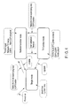
- FIG. 1 is an exemplary block diagram showing one example of the configuration of a television apparatus according to an embodiment
- FIGS. 2A , 2 B and 2 C are exemplary views showing images of a display device and signal routes when the television apparatus according to an embodiment shown in FIG. 1 is operated;
- FIGS. 3A and 3B are exemplary views showing other images of a display device when the television apparatus according to an embodiment shown in FIG. 1 is operated;
- FIG. 4 is a view to explain a classification of an operating mode of the television apparatus according to an embodiment shown in FIG. 1 ;
- FIG. 5A is a view showing a classification of application and hardware in first and second blocks
- FIG. 5B is a view to explain an application order when applications included in the first block is started in a state of taking the initiative and an application order when applications included in the second block is started in a state of taking the initiative;
- FIG. 6 is an exemplary block diagram showing the configuration of a part of first and second blocks
- FIG. 7A is an exemplary view showing a state when a conversion table of an operation signal is built up between first and second blocks.
- FIG. 7B is an exemplary view to explain an operation for making a response to an application, which is operated in the second block by means of a remote controller using a conversion table.
- CSPs content service providers
- These providers each make a request of an independent content providing topology, for example, an image display topology (layout).
- an object of the present invention is to provide a television apparatus, which is configured so that software development is small scale without making great changes to the hardware.
- a television apparatus comprises: a first block configured to be connected to a receiving block for a television signal; a second block independent from the first block, configured to be connected to a network; a bypass route configured to lead a bypass stream including an image signal from the first block to the second block; a processor configured to generate a return stream by inserting the image signal from the network into the image signal on the bypass stream, at the second block; a return pass configured to return the return stream to the first block; and a converter configured to convert the image signal included in the return stream into a signal for output and display, at the first block.
- a reference number 100 denotes a first block, which is supplied with a television signal received by a receiving block 101 .
- the first block 100 comprises a semiconductor integrated circuit, which is mounted with a circuit block for processing a television signal.
- the foregoing semiconductor integrated circuit is referred to as a system-on-a-chip (SoC).
- the first block 100 includes a converter 111 .
- the converter 111 decodes a digital television signal, and executes image quality control of a decoded image signal, and further, converts the image-quality-controlled image signal to a display signal.
- the first block 100 includes an operation signal receiver 112 , which receives and processes an operation signal from a remote controller 400 .
- the first block 100 includes a controller 113 , which collectively controls the function of the first block 100 .
- the first block 100 is connected with a wireless LAN module 104 .
- the wireless LAN module 104 is connected with an antenna 103 .
- the first block 100 is able to capture content from external content service providers via the wireless LAN module 104 .
- the foregoing content is moving picture content and news content.
- the first block 100 outputs a bypass stream including an image signal.
- the bypass stream is input to a second block 200 via a bypass route 121 .
- the second block 200 is connected to a connector 201 via a switch 202 .
- the connector 201 functions as a connection connector to an external network, that is, the Internet.
- the second block 200 includes a processor 211 .
- the processor 211 inserts (or multiplexes) an image signal from an external network input via the switch 202 with respect to an image signal from an external network input via the bypass route 121 .
- An output of the processor 211 passes a return route 214 as a return stream, and then, is sent to the first block 100 .
- the following two image signals are given as a foregoing image signal from an external network input to the second block 200 via the switch 202 .
- One is an image signal from the Internet input from the connector 201 .
- the other is an image signal captured by means of the wireless LAN module 104 .
- the switch 202 selects any one of the foregoing two image signals, and thereafter, supplies the selected image signal to the second block 200 .
- the second block 200 includes a controller 212 , which collectively controls the block 200 .
- the foregoing first and second blocks 100 and 200 are able to capture an image signal from an external connection device 300 via a switch 302 .
- a game console, an optical disk, a magnetic disk, a hard disk and a storage medium player such as a semiconductor memory are given as the external connection device 300 .
- An output from the external connection device 300 is supplied to the first or second block 100 or 200 via a High-Definition Multimedia Interface (HDMI) 301 and a switch 302 .
- HDMI High-Definition Multimedia Interface
- the first and second blocks 100 and 200 are associated by means of a control signal route 220 .
- the control signal route 220 transmits a first carrier signal from the first block 100 to the second block 200 , and transmits a second carrier signal from the second block 200 to the first block 100 .
- an operation signal (or control signal or data) acquired by the operation signal receiver 112 of the first block 100 is transmitted to the second block 200 by means of the first carrier signal.
- a control signal (or data) from the second block is transmitted to the first block 100 by means of the second carrier signal.
- the control signal controls each selection state of switches 202 and 302 .
- the foregoing bypass route 121 , return route 212 and control signal route 220 may be collectively built up by a High-Definition Multimedia Interface (HDMI), for example.
- HDMI High-Definition Multimedia Interface
- the foregoing apparatus receives a broadcast signal, and then, operates as a digital television apparatus for displaying a video image of a received program.
- this apparatus operates as follows. The operation will be described below with reference to FIGS. 2A and 2B .
- a receiving block 101 receives a broadcast program of a channel corresponding to an operation.
- a broadcast program stream output from the receiving block 101 is input to the converter 111 of the first block 100 .
- a vide signal included in the stream is fetched using a decoder while controlling the image quality of the decoded image signal, and further, makes a conversion of scanning lines and the number of pixels to output the image signal as a display signal.
- the output display signal is input to a display device 500 , and thereafter, displayed as a video image.
- FIG. 2A shows a signal route (stream Sg 1 ) in the foregoing operation.
- the television apparatus When the user operates a network mode specifying key 401 , which is provided on a remote controller 400 , the television apparatus is changed to a state capable of viewing content from a content service provider.
- a bypass stream including an image signal from the first block 100 is guided to the second block 200 via the bypass route 124 .
- the image signal is an image signal of a program selected by the receiving block 101 .
- a stream Sg 2 of FIG. 1 is formed in the bypass route 124 .
- a controller 212 includes a menu processor, and generates menu image signals related to a plurality of content service providers (CSPs) captured via a network.
- the controller 212 periodically compresses a part of an image signal sent from each CSP to store it in a memory, and then, supplies the image signal as a menu image signal.
- CSPs content service providers
- the processor 211 of the second block 200 inserts the foregoing menu image signal to the image signal from the bypass route 124 to generate a return stream Sg 3 .
- stream Sg 3 is returned to the first block 100 via a return route 214 .
- the converter 111 converts an image signal in the return stream into a display signal, and then, outputs it.
- the display device 500 displays an image 501 of the program received by the receiving block 101 and menu images 502 to 506 given according to a menu image signal created by the second block 200 .
- FIG. 1 and FIG. 2B show an example in which four menu images 502 to 506 are displayed.
- the menu image is scrolled to the left or right direction on a screen; in this way, many menu images are displayable. Namely, the number of content service providers increases, and thereby, the number of menu images increases.
- the controller 113 of the first block 100 recognizes whether content corresponding to each of menu images 503 to 506 is acquired via a route of the connector 201 or input via a route of the wireless LAN module 104 .
- the foregoing recognition is possible when the user sets a provider connection access address to an address manager (not shown) included in the controller 113 . Namely, it is possible to determine whether a provider provides content to the user via a wireless network or the Internet according to the foregoing access address.
- the controller 113 determines an image selection state from the content of a control signal from the remote controller 400 . Based on the foregoing determined result, the controller 113 controls the switch 202 so that the switch 202 selects any one of streams Sg 11 and Sg 12 .
- a cursor is positioned to any one of menu images on a screen of the display device 500 .
- a cursor 511 is positioned to the menu image 502 .
- a moving picture or movie or news program 501 provided by the selected content service provider is display on the whole of the screen of the display device as shown in FIG. 2C .
- a moving picture or movie or news program supplied from stream Sg 11 or stream Sg 12 of FIG. 1 is displayed.
- any one of streams Sg 11 and Sg 12 is selected by the switch 202 , and then, input to the second block 200 as a stream Sg 13 .
- video data included in stream Sg 13 is decoded, and then, input to the processor 211 as an image signal.
- a change or selection is made by the processor 211 .
- the switch 202 is controlled according to a control signal from the first block 100 .
- a bypass stream from the bypass route 124 is cut on the input side of the processor 211 .
- a bypass stream from the bypass route 124 is input to the processor 211 .
- menu images 502 to 506 according to menu image signals are displayed in a state of being again inserted to the image 501 of a TV-side image signal (e.g., screen state shown in FIG. 1 or FIG. 2B ).
- menu images 502 to 506 disappear. Then, the image 501 only of the TV-side image signal is displayed on the whole of the screen (i.e., screen state shown in FIG. 2A , in this case, a stream route is a bypass route ⁇ processor ⁇ return route).
- the image 501 of the TV-side image signal and menu images 502 to 506 are simultaneously displayed.
- the processor 211 may be changed to an operation of simply passing a bypass stream from the bypass route 124 . Then, when the user again operates the TV mode specifying key 402 or network mode specifying key 401 , the image 501 of the TV-side image signal and menu images 502 to 506 are again simultaneously displayed.
- An operation signal from the remote controller 400 is received by the operation signal receiver 112 , and further, recognized by the controller 113 of the first block as described above.
- the controller 113 determines whether or not an operation signal (control signal) is content to be transferred to the second block 200 . If the operation signal is an operation signal to be transferred to the second block 200 , the first block 100 multiples the operation signal with a first carrier signal, and thereafter, transmits it to the second block 200 .
- the controller 212 of the second block 200 receives the operation signal, and then, reflects the instruction to an operation of the second block 200 .
- the second block 200 multiples a control signal with a second carrier signal, and transmits it to the first block 100 from the second block 200 .
- the foregoing state of FIG. 2A is obtained after the supply of power is made with respect to the television apparatus.
- the state is obtained when a signal from the external connection device (e.g., game console, storage medium player) 300 is directly input to the first block 100 via the HDMI 301 and switch 302 (see FIG. 1 ).
- the user plays a game while viewing an image on the display device 500 after the game console is connected.
- an image signal from the first block 100 is directly converted to a display signal, and then, input to the display device 500 .
- FIG. 2B shows a screen on the display device 500 when the network mode specifying key 401 is operated as described above and a traveling state of a return stream.
- a video image of the content corresponding to the selected menu image is displayed on the whole of the screen.
- the background is a video image from the receiving block 101
- a video image from a network may be overlapped with a part of the foregoing background video image.
- the foregoing network video image may be optionally enlarged and reduced.
- FIG. 3A shows a state which is a video image of a content corresponding to a selected menu image is displayed on the whole of the screen.
- FIG. 3B shows a state which is a network video image is optionally enlarged and reduced so that a network video image is displayed on the left half of the screen while a television video image is display on the right half thereof.
- FIG. 4 is a view showing a classification of an operating mode of a television apparatus according to this embodiment. Power-on of a television apparatus, boot time or update time is simply a single mode, and the controller 113 of the first block 100 is mainly operated. As described in FIG. 2A , when the television apparatus is used in a state that an external connection device such as a game console is connected thereto, the apparatus is operated in a TV function mode. Moreover, in a state that the TV mode specifying key 402 is operated, viewing moving picture content and news video image from the wireless LAN module 104 is classified as the TV function mode. Operating the network mode specifying key 401 is classified as a network function mode.
- FIG. 5A shows each CSP application (original applications for decoding/converting/displaying data from each content service provider) included in first and second blocks 100 and 200 .
- Already-existing first and second CSP applications 131 and 132 are already included in the first block.
- In the first block 100 most of the ratio is occupied by television function-enabled hardware 116 .
- Most of the software load of the controller 113 relates to the control of the foregoing television function-enabled hardware 116 .
- the second block 200 includes many CSPs, that is, third to n CSP applications 233 and 234 . Further, the second block 200 includes a new CSP application expanded memory 235 for processing content from a new CSP.
- the second block 200 includes a format unity application 236 .
- the format unity application 236 is provided for achieving the following purpose. Specifically, a resolution, aspect ratio or basic format is different between an image signal (first image signal) from the first block 100 and an image signal (second image signal) acquired by the second block 200 via the Internet. For this reason, each format of the foregoing both image signals is unified to easily perform multiplexing. Basically, the format of the second image signal is unified to the format of the first image signal.
- First and second blocks 100 and 200 are provided with intercommunication applications 137 and 237 , respectively. These intercommunication applications 137 and 237 are used for transmission and analysis of a control signal between first and second blocks.
- a transceiver 213 , a demodulation-decoder 214 , and an encode-modulator 215 are included as hardware of the second block 200 . Therefore, the hardware scale of the second block 200 is smaller than that of the first block.
- the foregoing demodulation-decoder 214 and encode-modulator 215 may be built up by means of software.
- FIG. 5B shows the priority given to applications in a state that applications of the first block 100 take the initiative and in a state that applications of the second block 200 take the initiative.
- a state that applications of the first block 100 take the initiative i.e., TV mode specifying key 402 is operated
- basic applications managed in the first block 100 are operated.
- a video and graphics application and application 131 or 132 for CSP 1 or 2 have high priority.
- basic applications managed in the first block 100 are operated.
- a video and graphics application and applications 233 and 234 for CSP 3 to CSPn have high priority.
- FIG. 6 shows hardware included in first and second blocks 100 and 200 and the configuration of a controller.
- a decoder 121 a transport stream processor 122 , a switch 123 , a video processor 124 , a partial transport stream processor 127 , an interface 128 and a display signal output unit 126 are included in the converter 111 of FIG. 1 .
- a demodulator-decoder 214 an encoder-modulator 215 , a signal processor 223 and an interface 224 are included in the processor 211 of FIG. 1 .
- a transport stream of a channel received by the receiving block 101 (there is the case where the stream is plural) is input to the decoder 121 so that each stream is decoded.
- a transport stream selected for viewing is input to the switch 123 and the partial transport stream processor 127 .
- the switch 123 In a TV function mode, the switch 123 is closed, and a transport stream to be viewed is processed by the video processor 125 , and then, converted to a base-band image signal.
- the video processor 125 selectively executes an image quality control, color control and conversion of the number of pixels. Further, the video processor 125 executes a level control and conversion of the number of lines for the output to a display device.
- a transport stream to be viewed is transmitted to the second block 200 via the partial transport stream processor 127 and the interface 128 .
- the transmitted transport stream is input to the signal processor 223 via the bypass route 124 and the interface 224 .
- an image signal of the transport stream is decoded, and thereafter, synthesized with a menu image or an image signal from a network.
- the synthesized image signal is adjusted as a return stream by the interface 224 , and then, returned to the first block 100 via the return route 214 .
- the return stream is input to the video processor 125 via the interface 128 , and then, converted to a base-band image signal.
- the video processor 125 selectively executes an image quality control, color control and conversion of the number of pixels. Further, the video processor 125 executes a level control and conversion of the number of lines for the output to a display device.
- Controllers 113 and 212 of first and second blocks 100 and 200 mutually make an exchange of a control signal via a control signal route 220 .
- These controllers 113 and 212 include application managers 130 and 230 for managing applications as shown in FIGS. 5A and 5B , respectively.
- an operation signal from the remote controller 400 is acquired by the operation signal receiver 112 , and then, supplied to the controller 113 .
- the controller 113 analyzes the content of the operation signal, and thereafter, reflects an operation of the first block 100 to the operation signal if the analyzed signal is an operation signal related to the control of the first block 100 .
- the foregoing operation signal does not relate to the control of the first block 100 , but includes the control of the second block 200 .
- a conversion table of a remote controller operation signal processor 133 is referred.
- an operation code used for an application, which is currently operated, is described therein.
- a remote controller operation key code corresponding to the foregoing operation code is described.
- the table including the foregoing codes is transmitted from the second block 200 .
- the second block 200 includes a demodulation-decoder 214 and an encode-modulator 215 . Further, the second block 200 includes a signal processor 223 and an interface 224 .
- the controller 212 includes an application manager 230 for managing applications described in FIG. 5A . Further, the controller 212 includes a key code processor 233 , which associates a necessary operation code with a remote controller operation code in accordance with each application to create a conversion table.
- the key code processor 233 When a CSP application is operated, the key code processor 233 describes an operation code (referred to as application operating code) required for the application on each row of the first column of the conversion table. Further, the unit 233 describes a remote controller key code corresponding to the application operating code on each row of the second column of the conversion table.
- the foregoing table creating application may be previously transmitted from a content provider. Or, the table creating application may be previously installed in the second block 200 by a maker, who produces a television apparatus, or may be updated by service using the Internet.
- a table created by the key code processor 233 is notified to the first block 100 as a conversion table. Then, the first block 100 stores the conversion table in the operation signal processor 133 . When an operation from the remote controller 400 is made, the first block 100 converts a remote controller key code to an application operating code using the conversion table, and then, transfers it to the second block.
- FIG. 7A is a view to explain the case where a CSP application is an application, which makes a question.
- a screen 551 by a CSP application is displayed on a display device 500 .
- the user operates the remote controller 400 to describe an answer in blanks 561 to 564 .
- a cursor key is used in order to select a blank.
- the cursor is moved up and down only. Therefore, the cursor and determination key 422 of the remote controller 400 up, and down operation keys, are used as the foregoing cursor operation.
- a numeric keypad (1 to 9, 0) 421 of the remote controller 400 is used to specify an answer.
- the numeric keypad is used for channel selection in a TV function mode.
- the enter key is used as an operation key for confirming an answer after the answer is input.
- an operation key 423 of a recording/reproducing apparatus of a recording medium is usually used for the following case. For example, one is the case where the user re-corrects an answer, and proceeds to another question for selecting a question (or high level question). Or, the other is the case where the user returns to the previously answered question (or low level question).
- FIG. 7B is a flowchart when the user makes an answer to the foregoing question.
- the user selects a blank for inputting an answer to a question using a cursor, and then, inputs an answer by operating a numeric keypad, and thereafter, operates an enter key.
Abstract
Description
Claims (9)
Applications Claiming Priority (2)
| Application Number | Priority Date | Filing Date | Title |
|---|---|---|---|
| JP2010-189845 | 2010-08-26 | ||
| JP2010189845A JP4970579B2 (en) | 2010-08-26 | 2010-08-26 | Television equipment |
Publications (2)
| Publication Number | Publication Date |
|---|---|
| US20120050615A1 US20120050615A1 (en) | 2012-03-01 |
| US8310593B2 true US8310593B2 (en) | 2012-11-13 |
Family
ID=45696779
Family Applications (1)
| Application Number | Title | Priority Date | Filing Date |
|---|---|---|---|
| US13/186,354 Active US8310593B2 (en) | 2010-08-26 | 2011-07-19 | Television apparatus |
Country Status (2)
| Country | Link |
|---|---|
| US (1) | US8310593B2 (en) |
| JP (1) | JP4970579B2 (en) |
Families Citing this family (1)
| Publication number | Priority date | Publication date | Assignee | Title |
|---|---|---|---|---|
| EP2610744A1 (en) * | 2011-12-28 | 2013-07-03 | Samsung Electronics Co., Ltd. | Electronic system, control method thereof, display apparatus, upgrade apparatus, and data input/output processing method of display apparatus |
Citations (9)
| Publication number | Priority date | Publication date | Assignee | Title |
|---|---|---|---|---|
| US6073171A (en) * | 1997-01-23 | 2000-06-06 | Zenith Electronics Corporation | Two-way communication protocol for a web television |
| WO2000052927A1 (en) | 1999-03-01 | 2000-09-08 | Sony Electronics Inc | Method and device for providing two different types of service in a menu |
| WO2001011873A1 (en) | 1999-08-05 | 2001-02-15 | Gentor.Com Inc. | Internet tv |
| JP2004264588A (en) | 2003-02-28 | 2004-09-24 | Toshiba Corp | Information processor |
| JP2005244716A (en) | 2004-02-27 | 2005-09-08 | Toshiba Corp | Television broadcast receiving system |
| JP2005260330A (en) | 2004-03-09 | 2005-09-22 | Toshiba Corp | Broadcast receiver and broadcast receiving method |
| JP2006318281A (en) | 2005-05-13 | 2006-11-24 | Sony Computer Entertainment Inc | Image processing system |
| US20070168622A1 (en) | 2006-01-18 | 2007-07-19 | Sehat Sutardja | Processor architecture |
| US7454777B1 (en) * | 1999-03-01 | 2008-11-18 | Sony Corporation | Satellite system/internet system with display option palette with multiple filtering options |
-
2010
- 2010-08-26 JP JP2010189845A patent/JP4970579B2/en not_active Expired - Fee Related
-
2011
- 2011-07-19 US US13/186,354 patent/US8310593B2/en active Active
Patent Citations (19)
| Publication number | Priority date | Publication date | Assignee | Title |
|---|---|---|---|---|
| US6073171A (en) * | 1997-01-23 | 2000-06-06 | Zenith Electronics Corporation | Two-way communication protocol for a web television |
| WO2000052927A1 (en) | 1999-03-01 | 2000-09-08 | Sony Electronics Inc | Method and device for providing two different types of service in a menu |
| US6348932B1 (en) | 1999-03-01 | 2002-02-19 | Sony Corporation | Provide two different types of service in a menu |
| JP2002538735A (en) | 1999-03-01 | 2002-11-12 | ソニー エレクトロニクス インク | Apparatus and method for displaying two different services in a menu |
| US7454777B1 (en) * | 1999-03-01 | 2008-11-18 | Sony Corporation | Satellite system/internet system with display option palette with multiple filtering options |
| WO2001011873A1 (en) | 1999-08-05 | 2001-02-15 | Gentor.Com Inc. | Internet tv |
| JP2001094966A (en) | 1999-08-05 | 2001-04-06 | Gentor Dot Com Inc | Internet television receiver |
| US7174397B2 (en) | 2003-02-28 | 2007-02-06 | Kabushiki Kaisha Toshiba | Information processing apparatus that displays image data |
| JP2004264588A (en) | 2003-02-28 | 2004-09-24 | Toshiba Corp | Information processor |
| US20040212607A1 (en) | 2003-02-28 | 2004-10-28 | Yuichi Tomiyasu | Information processing apparatus that displays image data |
| JP2005244716A (en) | 2004-02-27 | 2005-09-08 | Toshiba Corp | Television broadcast receiving system |
| JP2005260330A (en) | 2004-03-09 | 2005-09-22 | Toshiba Corp | Broadcast receiver and broadcast receiving method |
| JP2006318281A (en) | 2005-05-13 | 2006-11-24 | Sony Computer Entertainment Inc | Image processing system |
| US20090066706A1 (en) | 2005-05-13 | 2009-03-12 | Sony Computer Entertainment Inc. | Image Processing System |
| US20070168622A1 (en) | 2006-01-18 | 2007-07-19 | Sehat Sutardja | Processor architecture |
| JP2007220085A (en) | 2006-01-18 | 2007-08-30 | Marvell World Trade Ltd | Processor architecture |
| US7600081B2 (en) | 2006-01-18 | 2009-10-06 | Marvell World Trade Ltd. | Processor architecture having multi-ported memory |
| US20100023705A1 (en) | 2006-01-18 | 2010-01-28 | Sehat Sutardja | Processor architecture having multi-ported memory |
| US7761668B2 (en) | 2006-01-18 | 2010-07-20 | Marvell World Trade Ltd. | Processor architecture having multi-ported memory |
Non-Patent Citations (3)
| Title |
|---|
| Hatanaka et al. 2010. VX700 Series-The Super Narrow Bezel Internet Capable LED TV with LED Backlighting, 4 pages. |
| Hatanaka et al. 2010. VX700 Series—The Super Narrow Bezel Internet Capable LED TV with LED Backlighting, 4 pages. |
| Notice of Reasons for Rejection mailed by the Japan Patent Office on Dec. 13, 2011 in corresponding Japanese Patent Application No. 2010-189845. |
Also Published As
| Publication number | Publication date |
|---|---|
| JP4970579B2 (en) | 2012-07-11 |
| US20120050615A1 (en) | 2012-03-01 |
| JP2012049814A (en) | 2012-03-08 |
Similar Documents
| Publication | Publication Date | Title |
|---|---|---|
| RU2565003C2 (en) | Multimedia device connected to external electronic device and method of its control | |
| US20100165200A1 (en) | Display control device, display control method and display control program | |
| US20140215507A1 (en) | Personalized passive content delivery | |
| EP2048882A1 (en) | Display apparatus | |
| CN103024522A (en) | Method of managing contents and image display device using the same | |
| KR20100036664A (en) | A display apparatus capable of moving image and the method thereof | |
| CN112153406A (en) | Live broadcast data generation method, display equipment and server | |
| US20050017890A1 (en) | Remote control device and method using structured data format | |
| US20090147140A1 (en) | Image apparatus for processing plurality of images and control method thereof | |
| CN111726673B (en) | Channel switching method and display device | |
| US10219045B2 (en) | Server, image providing apparatus, and image providing system comprising same | |
| US20080152319A1 (en) | Apparatus for processing multimedia stream and method for transmitting multimedia stream | |
| CN112995733B (en) | Display device, device discovery method and storage medium | |
| US8310593B2 (en) | Television apparatus | |
| CN112533056B (en) | Display device and sound reproduction method | |
| CN111385631A (en) | Display device, communication method and storage medium | |
| US8561111B2 (en) | Video processor, television display device, and video processing method | |
| JP5362065B2 (en) | Television equipment | |
| CN113727163B (en) | Display device | |
| US20070083891A1 (en) | Image processing apparatus and control method thereof | |
| US8538235B2 (en) | Reproducing device, reproducing method, program and recording medium | |
| US20230247260A1 (en) | Mobile terminal | |
| US10555028B2 (en) | Image providing device | |
| US20230247261A1 (en) | Image display apparatus | |
| CN115086722B (en) | Display method and display device for secondary screen content |
Legal Events
| Date | Code | Title | Description |
|---|---|---|---|
| AS | Assignment |
Owner name: KABUSHIKI KAISHA TOSHIBA, JAPAN Free format text: ASSIGNMENT OF ASSIGNORS INTEREST;ASSIGNORS:MOGI, HISASHI;MORITANI, MITSUAKI;SIGNING DATES FROM 20110425 TO 20110426;REEL/FRAME:026616/0510 |
|
| STCF | Information on status: patent grant |
Free format text: PATENTED CASE |
|
| FPAY | Fee payment |
Year of fee payment: 4 |
|
| AS | Assignment |
Owner name: TOSHIBA LIFESTYLE PRODUCTS & SERVICES CORPORATION, Free format text: ASSIGNMENT OF PARTIAL RIGHTS;ASSIGNOR:KABUSHIKI KAISHA TOSHIBA;REEL/FRAME:040458/0840 Effective date: 20160630 Owner name: TOSHIBA VISUAL SOLUTIONS CORPORATION, JAPAN Free format text: CORPORATE SPLIT;ASSIGNOR:TOSHIBA LIFESTYLE PRODUCTS & SERVICES CORPORATION;REEL/FRAME:040458/0859 Effective date: 20160713 |
|
| AS | Assignment |
Owner name: TOSHIBA VISUAL SOLUTIONS CORPORATION, JAPAN Free format text: ASSIGNMENT OF ASSIGNORS INTEREST;ASSIGNOR:KABUSHIKI KAISHA TOSHIBA;REEL/FRAME:046881/0120 Effective date: 20180420 |
|
| AS | Assignment |
Owner name: HISENSE VISUAL TECHNOLOGY CO., LTD., CHINA Free format text: ASSIGNMENT OF ASSIGNORS INTEREST;ASSIGNOR:TOSHIBA VISUAL SOLUTIONS CORPORATION;REEL/FRAME:051493/0333 Effective date: 20191225 |
|
| MAFP | Maintenance fee payment |
Free format text: PAYMENT OF MAINTENANCE FEE, 8TH YEAR, LARGE ENTITY (ORIGINAL EVENT CODE: M1552); ENTITY STATUS OF PATENT OWNER: LARGE ENTITY Year of fee payment: 8 |