US8259028B2 - Reflector antenna radome attachment band clamp - Google Patents
Reflector antenna radome attachment band clamp Download PDFInfo
- Publication number
- US8259028B2 US8259028B2 US12/636,068 US63606809A US8259028B2 US 8259028 B2 US8259028 B2 US 8259028B2 US 63606809 A US63606809 A US 63606809A US 8259028 B2 US8259028 B2 US 8259028B2
- Authority
- US
- United States
- Prior art keywords
- reflector
- band clamp
- width
- lip
- dish
- Prior art date
- Legal status (The legal status is an assumption and is not a legal conclusion. Google has not performed a legal analysis and makes no representation as to the accuracy of the status listed.)
- Active, expires
Links
- 230000008878 coupling Effects 0.000 claims abstract description 5
- 238000010168 coupling process Methods 0.000 claims abstract description 5
- 238000005859 coupling reaction Methods 0.000 claims abstract description 5
- 238000000034 method Methods 0.000 claims description 5
- 230000005855 radiation Effects 0.000 description 7
- 238000009434 installation Methods 0.000 description 6
- 238000004519 manufacturing process Methods 0.000 description 6
- 230000006872 improvement Effects 0.000 description 5
- 239000000463 material Substances 0.000 description 5
- 230000001105 regulatory effect Effects 0.000 description 4
- 230000007613 environmental effect Effects 0.000 description 3
- 238000012423 maintenance Methods 0.000 description 3
- 238000004806 packaging method and process Methods 0.000 description 3
- 230000001629 suppression Effects 0.000 description 3
- 230000015556 catabolic process Effects 0.000 description 2
- 238000006731 degradation reaction Methods 0.000 description 2
- 230000000694 effects Effects 0.000 description 2
- 239000002184 metal Substances 0.000 description 2
- 238000012986 modification Methods 0.000 description 2
- 230000004048 modification Effects 0.000 description 2
- 238000012384 transportation and delivery Methods 0.000 description 2
- IHHSSHCBRVYGJX-UHFFFAOYSA-N 6-chloro-2-methoxyacridin-9-amine Chemical compound C1=C(Cl)C=CC2=C(N)C3=CC(OC)=CC=C3N=C21 IHHSSHCBRVYGJX-UHFFFAOYSA-N 0.000 description 1
- 239000011358 absorbing material Substances 0.000 description 1
- 238000000576 coating method Methods 0.000 description 1
- 230000005574 cross-species transmission Effects 0.000 description 1
- 230000007812 deficiency Effects 0.000 description 1
- 238000009826 distribution Methods 0.000 description 1
- 230000003116 impacting effect Effects 0.000 description 1
- 230000007774 longterm Effects 0.000 description 1
- 230000013011 mating Effects 0.000 description 1
- 230000002093 peripheral effect Effects 0.000 description 1
- 238000007747 plating Methods 0.000 description 1
- 230000009467 reduction Effects 0.000 description 1
- 238000003466 welding Methods 0.000 description 1
Images


Classifications
-
- H—ELECTRICITY
- H01—ELECTRIC ELEMENTS
- H01Q—ANTENNAS, i.e. RADIO AERIALS
- H01Q15/00—Devices for reflection, refraction, diffraction or polarisation of waves radiated from an antenna, e.g. quasi-optical devices
- H01Q15/14—Reflecting surfaces; Equivalent structures
-
- H—ELECTRICITY
- H01—ELECTRIC ELEMENTS
- H01Q—ANTENNAS, i.e. RADIO AERIALS
- H01Q1/00—Details of, or arrangements associated with, antennas
- H01Q1/42—Housings not intimately mechanically associated with radiating elements, e.g. radome
-
- H—ELECTRICITY
- H01—ELECTRIC ELEMENTS
- H01Q—ANTENNAS, i.e. RADIO AERIALS
- H01Q15/00—Devices for reflection, refraction, diffraction or polarisation of waves radiated from an antenna, e.g. quasi-optical devices
- H01Q15/14—Reflecting surfaces; Equivalent structures
- H01Q15/16—Reflecting surfaces; Equivalent structures curved in two dimensions, e.g. paraboloidal
-
- H—ELECTRICITY
- H01—ELECTRIC ELEMENTS
- H01Q—ANTENNAS, i.e. RADIO AERIALS
- H01Q19/00—Combinations of primary active antenna elements and units with secondary devices, e.g. with quasi-optical devices, for giving the antenna a desired directional characteristic
- H01Q19/10—Combinations of primary active antenna elements and units with secondary devices, e.g. with quasi-optical devices, for giving the antenna a desired directional characteristic using reflecting surfaces
- H01Q19/12—Combinations of primary active antenna elements and units with secondary devices, e.g. with quasi-optical devices, for giving the antenna a desired directional characteristic using reflecting surfaces wherein the surfaces are concave
Definitions
- This invention relates to microwave reflector antennas. More particularly, the invention relates to a reflector antenna with a radome and reflector dish interconnection band clamp which enhances signal pattern and mechanical interconnection characteristics.
- the open end of a reflector antenna is typically enclosed by a radome coupled to the distal end of the reflector dish.
- the radome provides environmental protection and improves wind load characteristics of the antenna.
- Edges and/or channel paths of the reflector dish, radome and/or interconnection hardware may diffract or enable spill-over of signal energy present in these areas, introducing undesirable backlobes into the reflector antenna signal pattern quantified as the front to back ratio (F/B) of the antenna.
- the F/B is regulated by international standards, and is specified by for example, the FCC in 47 CFR Ch.1 Part 101.115 in the United States, by ETSI in EN302217-4-1 and EN302217-4-12 in Europe, and by ACMA RALI FX 3 Appendix 11 in Australia.
- Prior antenna signal pattern backlobe suppression techniques include adding a backlobe suppression ring to the radome, for example via metalizing of the radome periphery as disclosed in commonly owned U.S. Pat. No. 7,138,958, titled “Reflector Antenna Radome with Backlobe Suppressor Ring and Method of Manufacturing” issued Nov. 21, 2006 to Syed et al, hereby incorporated by reference in its entirety.
- the required metalizing operations may increase manufacturing complexity and/or cost, including elaborate coupling arrangements configured to securely retain the shroud upon the reflector dish without presenting undesired reflection edges, signal leakage paths and/or extending the overall size of the radome.
- the thin metalized ring layer applied to the periphery of the radome may be fragile, requiring increased care to avoid damage during delivery and/or installation.
- Reflectors employing castellated edge geometries to generate constructive interference of the edge diffraction components have also been shown to improve the F/B, for example as disclosed in commonly owned Canada Patent No. CA887303 “Backlobe Reduction in Reflector-Type Antennas” by Holtum et al. Such arrangements increase the overall diameter of the antenna, which may complicate radome attachment, packaging and installation.
- a shroud to a reflector antenna improves the signal pattern generally as a function of the shroud length, but also similarly introduces significant costs as the increasing length of the shroud also increases wind loading of the reflector antenna, requiring a corresponding increase in the antenna and antenna support structure strength. Further, an interconnection between the shroud and a radome may introduce significant F/B degradation.
- a conventional band clamp 1 applied to retain a radome 3 upon the reflector dish 7 or shroud may introduce diffraction edges and/or signal leakage paths, for example as shown in FIG. 1 .
- Metal taping, RF gaskets or the like may be applied to reduce F/B degradation resulting from band clamp use.
- these materials and procedures increase manufacturing costs and/or installation complexity and may be of limited long-term reliability.
- FIG. 1 is a schematic enlarged cut-away side view of a conventional prior art band clamp radome and reflector dish interconnection, demonstrating an RF signal leakage path.
- FIG. 2 is a schematic isometric cut-away view of a reflector antenna with radome to reflector dish band clamp interconnection.
- FIG. 3 is a schematic partial cut-away side view of a radome to reflector dish band clamp interconnection.
- FIG. 4 is an enlarged cut-away side view of a first exemplary radome to reflector dish band clamp interconnection.
- FIG. 5 is a graph illustrating a range of exemplary band clamp distal lip inner diameter to reflector dish aperture ratios and their effect upon corresponding reflector antenna F/B over a range of operating frequencies.
- FIG. 6 is a graph illustrating a range of band clamp widths and their effect upon corresponding reflector antenna F/B.
- FIG. 7 is a graph comparing measured co-polar F/B performance related to RF signal leakage between conventional band clamp and presently disclosed “new” band clamp configurations.
- FIG. 8 is a graph comparing measured cross-polar F/B performance related to RF signal leakage between conventional band clamp and presently disclosed “new” band clamp configurations.
- FIG. 9 is a graph of measured co-polar radiation patterns of a 0.6 m reflector antenna with a bandclamp with a 1.1 wavelength width.
- FIG. 10 is a graph of measured cross-polar radiation patterns of a 0.6 m reflector antenna with a bandclamp with a 1.1 wavelength width.
- FIG. 11 is an enlarged cut-away side view of a second exemplary radome to reflector dish band clamp interconnection.
- FIG. 12 is an enlarged cut-away side view of a third exemplary radome to reflector dish band clamp interconnection, including a width ring.
- FIG. 13 is a graph comparing predicted F/B enhancement with a band clamp of width of 0.5 and 1.2 wavelengths.
- FIG. 14 is a graph of measured co-polar radiation patterns for a reflector antenna with a band clamp with a 0.5 wavelength width.
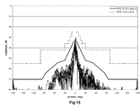
- FIG. 15 is a graph of measured cross-polar radiation patterns for a reflector antenna with a band clamp with a 0.5 wavelength width.
- FIG. 16 is a graph of measured co-polar radiation patterns for a reflector antenna with a band clamp with a 1.2 wavelength width.
- FIG. 17 is a graph of measured cross-polar radiation patterns for a reflector antenna with a band clamp with a 1.2 wavelength width.
- FIG. 18 is an enlarged cut-away side view of a third exemplary radome to reflector dish band clamp interconnection, including a width ring with radial outward bend.
- FIG. 19 is a graph comparing predicted F/B enhancement with a band clamp with a width ring configuration of between 0 and 60 degrees radial outward bend.
- a band clamp 1 is generally operative to retain a radome 3 upon the open distal end 5 of a reflector dish 7 , creating an environmental seal that protects the reflector dish 7 , subreflector 9 and/or feed 11 of a reflector antenna 13 from environmental fouling.
- the band clamp 1 is provided with inward facing distal and proximal lips 15 , 17 .
- a turnback region 19 of the proximal lip 17 is dimensioned to engage the outer surface 21 of the signal area 23 of the reflector dish 7 .
- the turnback region 19 may be applied, for example, as an outward bend prior to the inward end 25 of the proximal lip 17 .
- the diameter of the band clamp 1 is progressively reduced, driving the turnback region 19 against the convex outer surface 21 of the signal area 23 of the reflector dish 7 , into a uniform circumferential interference fit.
- the turnback region 19 slides progressively inward along the outer surface 21 of the signal area 23 of the reflector dish 7 toward the reflector dish proximal end 27 .
- the distal lip 15 of the band clamp 1 also moves towards the reflector dish proximal end 27 , securely clamping the radome 3 against the distal end 5 of the reflector dish 7 . Because the interference fit between the turnback region 19 and the outer surface 21 of the reflector dish 7 is circumferentially uniform, any RF leakage between these surfaces is reduced.
- the radome 3 may be provided with a greater diameter than the reflector dish 7 , an annular lip 29 of the radome 3 periphery mating with an outer diameter of the distal end 5 of the reflector dish 7 , keying the radome 3 coaxial with the reflector dish 7 and providing surface area for spacing the band clamp 1 from the signal area 23 of the reflector dish 7 .
- the flanges may be dimensioned and the band clamp 1 similarly dimensioned such that the distal lip 15 of the band clamp 1 is even with or extends slightly inward of a reflector aperture H, defined as the largest diameter of the reflector dish 7 surface upon which signal energy is distributed by the subreflector 9 , to form a band clamp inner diameter D.
- a reflector aperture H defined as the largest diameter of the reflector dish 7 surface upon which signal energy is distributed by the subreflector 9 , to form a band clamp inner diameter D.
- the band clamp inner diameter D may be dimensioned with respect to reflector aperture H, resulting in significant F/B enhancement as illustrated in FIG. 5 .
- a D/H ratio of 0.97-1.0 may be applied.
- band clamp 1 width “A” determines the distance between band clamp 1 outer corner(s) 31 acting as diffraction/scatter surfaces.
- normalized F/B is improved when the width “A” is between 0.8 and 1.5 wavelengths of the operating frequency, which can be operative to generate mutual interference of surface currents traveling along the band clamp 1 outer periphery and/or scatter interference.
- FIGS. 7 and 8 illustrate measured backlobe levels of co-polar and cross-polar radiation patterns in the 26 GHz band within the regulatory envelopes at greater than 71 dB with the FIG. 4 band clamp 1 configuration, in which the width “A” is equal to 1.1 wavelengths.
- the optimal range of widths “A” may be difficult to achieve for some operating frequencies without incorporating further structure in the radome and/or reflector dish periphery.
- the width “A” may be increased via the application of a fold 33 in the band clamp from the desired extent of the width “A” back toward the reflector dish 7 .
- the pictured embodiment is simplified for demonstration purposes with respect to extending the width “A” but may similarly be applied with a fold 33 and proximal lip 17 that extends further inward and includes a turnback region 19 contacting the outer surface 21 of the signal area 23 of the reflector dish 7 .
- an extension of the width “A” may be cost effectively achieved by attaching a further width ring 35 of metallic and/or metal coated material to the band clamp 1 outer diameter.
- the width ring 35 may be applied with any desired width, cost effectively securely attached by spot welding or fasteners such as screws, rivets or the like.
- FIG. 13 illustrates 18 GHz band RF modeling software predictions of F/B improvement between a width ring 35 width “A” of 0.5 and 1.2 wavelengths.
- the width ring 35 may be provided in an angled configuration as demonstrated in FIG. 18 .
- RF modeling software predictions of F/B improvement indicate progressively increasing improvement as the angle applied increases from zero (flat width ring 35 cross section) to sixty degrees of diffraction gradient.
- the disclosed band clamp 1 can enable significant manufacturing, delivery, installation and/or maintenance efficiencies. Because the band clamp 1 enables simplified radome 3 and reflector dish 7 periphery geometries, the resulting reflector antenna 13 may have improved materials and manufacturing costs. Because the band clamp 1 is simply and securely attached, installation and maintenance may be simplified compared to prior reflector antenna 13 configurations with complex peripheral geometries, delicate back lobe suppression ring coatings, platings and/or RF absorbing materials. Because the band clamp 1 may be compact and applied close to the reflector antenna aperture H, the overall diameter of the reflector antenna 13 may be reduced, which can reduce the reflector antenna 13 wind loading characteristics and the required packaging dimensions.
Abstract
Description
| Table of |
| 1 | |
| 3 | |
| 5 | |
| 7 | reflector dish |
| 9 | |
| 11 | |
| 13 | |
| 15 | |
| 17 | |
| 19 | |
| 21 | |
| 23 | |
| 25 | |
| 27 | |
| 29 | |
| 31 | |
| 33 | |
| 35 | width ring |
Claims (20)
Priority Applications (6)
| Application Number | Priority Date | Filing Date | Title |
|---|---|---|---|
| US12/636,068 US8259028B2 (en) | 2009-12-11 | 2009-12-11 | Reflector antenna radome attachment band clamp |
| CN201080056187.7A CN102714343B (en) | 2009-12-11 | 2010-09-15 | Band clamp, reflector antenna, and method for reducing front-to-rear ration of reflector antenna |
| PCT/IB2010/054173 WO2011070451A2 (en) | 2009-12-11 | 2010-09-15 | Reflector antenna radome attachment band clamp |
| EP10835569.4A EP2510576B1 (en) | 2009-12-11 | 2010-09-15 | Reflector antenna radome attachment band clamp |
| BR112012013654-2A BR112012013654B1 (en) | 2009-12-11 | 2010-09-15 | CLAMP FOR ATTACHING A RADOME TO THE DISTAL END OF A REFLECTOR DISK METHOD FOR REDUCING THE FRONT-REAR RATIO OF A REFLECTOR ANTENNA WITH A REFLECTOR DISK AND A RADOME AND REFLECTOR ANTENNA |
| US13/600,544 US9083083B2 (en) | 2009-12-11 | 2012-08-31 | Radome attachment band clamp |
Applications Claiming Priority (1)
| Application Number | Priority Date | Filing Date | Title |
|---|---|---|---|
| US12/636,068 US8259028B2 (en) | 2009-12-11 | 2009-12-11 | Reflector antenna radome attachment band clamp |
Related Child Applications (1)
| Application Number | Title | Priority Date | Filing Date |
|---|---|---|---|
| US13/600,544 Continuation-In-Part US9083083B2 (en) | 2009-12-11 | 2012-08-31 | Radome attachment band clamp |
Publications (2)
| Publication Number | Publication Date |
|---|---|
| US20110140983A1 US20110140983A1 (en) | 2011-06-16 |
| US8259028B2 true US8259028B2 (en) | 2012-09-04 |
Family
ID=44142338
Family Applications (1)
| Application Number | Title | Priority Date | Filing Date |
|---|---|---|---|
| US12/636,068 Active 2031-04-15 US8259028B2 (en) | 2009-12-11 | 2009-12-11 | Reflector antenna radome attachment band clamp |
Country Status (4)
| Country | Link |
|---|---|
| US (1) | US8259028B2 (en) |
| EP (1) | EP2510576B1 (en) |
| CN (1) | CN102714343B (en) |
| WO (1) | WO2011070451A2 (en) |
Cited By (141)
| Publication number | Priority date | Publication date | Assignee | Title |
|---|---|---|---|---|
| US20130002515A1 (en) * | 2009-12-11 | 2013-01-03 | Andrew Llc | Radome Attachment Band Clamp |
| US20130099991A1 (en) * | 2011-10-24 | 2013-04-25 | Andew Llc | Method and Apparatus for Radome and Reflector Dish Interconnection |
| US9577323B2 (en) | 2014-03-07 | 2017-02-21 | Commscope Technologies Llc | Radome—reflector assembly mechanism |
| US9608740B2 (en) | 2015-07-15 | 2017-03-28 | At&T Intellectual Property I, L.P. | Method and apparatus for launching a wave mode that mitigates interference |
| US9640850B2 (en) | 2015-06-25 | 2017-05-02 | At&T Intellectual Property I, L.P. | Methods and apparatus for inducing a non-fundamental wave mode on a transmission medium |
| US9667317B2 (en) | 2015-06-15 | 2017-05-30 | At&T Intellectual Property I, L.P. | Method and apparatus for providing security using network traffic adjustments |
| US9674711B2 (en) | 2013-11-06 | 2017-06-06 | At&T Intellectual Property I, L.P. | Surface-wave communications and methods thereof |
| US9685992B2 (en) | 2014-10-03 | 2017-06-20 | At&T Intellectual Property I, L.P. | Circuit panel network and methods thereof |
| US9705610B2 (en) | 2014-10-21 | 2017-07-11 | At&T Intellectual Property I, L.P. | Transmission device with impairment compensation and methods for use therewith |
| US9705561B2 (en) | 2015-04-24 | 2017-07-11 | At&T Intellectual Property I, L.P. | Directional coupling device and methods for use therewith |
| US9722318B2 (en) | 2015-07-14 | 2017-08-01 | At&T Intellectual Property I, L.P. | Method and apparatus for coupling an antenna to a device |
| US9729197B2 (en) | 2015-10-01 | 2017-08-08 | At&T Intellectual Property I, L.P. | Method and apparatus for communicating network management traffic over a network |
| US9735833B2 (en) | 2015-07-31 | 2017-08-15 | At&T Intellectual Property I, L.P. | Method and apparatus for communications management in a neighborhood network |
| US9742521B2 (en) | 2014-11-20 | 2017-08-22 | At&T Intellectual Property I, L.P. | Transmission device with mode division multiplexing and methods for use therewith |
| US9742462B2 (en) | 2014-12-04 | 2017-08-22 | At&T Intellectual Property I, L.P. | Transmission medium and communication interfaces and methods for use therewith |
| US9749013B2 (en) | 2015-03-17 | 2017-08-29 | At&T Intellectual Property I, L.P. | Method and apparatus for reducing attenuation of electromagnetic waves guided by a transmission medium |
| US9748626B2 (en) | 2015-05-14 | 2017-08-29 | At&T Intellectual Property I, L.P. | Plurality of cables having different cross-sectional shapes which are bundled together to form a transmission medium |
| US9749053B2 (en) | 2015-07-23 | 2017-08-29 | At&T Intellectual Property I, L.P. | Node device, repeater and methods for use therewith |
| US9762289B2 (en) | 2014-10-14 | 2017-09-12 | At&T Intellectual Property I, L.P. | Method and apparatus for transmitting or receiving signals in a transportation system |
| US9769020B2 (en) | 2014-10-21 | 2017-09-19 | At&T Intellectual Property I, L.P. | Method and apparatus for responding to events affecting communications in a communication network |
| US9768833B2 (en) | 2014-09-15 | 2017-09-19 | At&T Intellectual Property I, L.P. | Method and apparatus for sensing a condition in a transmission medium of electromagnetic waves |
| US9769128B2 (en) | 2015-09-28 | 2017-09-19 | At&T Intellectual Property I, L.P. | Method and apparatus for encryption of communications over a network |
| US9780834B2 (en) | 2014-10-21 | 2017-10-03 | At&T Intellectual Property I, L.P. | Method and apparatus for transmitting electromagnetic waves |
| US9788326B2 (en) | 2012-12-05 | 2017-10-10 | At&T Intellectual Property I, L.P. | Backhaul link for distributed antenna system |
| US9787412B2 (en) | 2015-06-25 | 2017-10-10 | At&T Intellectual Property I, L.P. | Methods and apparatus for inducing a fundamental wave mode on a transmission medium |
| US9793954B2 (en) | 2015-04-28 | 2017-10-17 | At&T Intellectual Property I, L.P. | Magnetic coupling device and methods for use therewith |
| US9793951B2 (en) | 2015-07-15 | 2017-10-17 | At&T Intellectual Property I, L.P. | Method and apparatus for launching a wave mode that mitigates interference |
| US9793955B2 (en) | 2015-04-24 | 2017-10-17 | At&T Intellectual Property I, Lp | Passive electrical coupling device and methods for use therewith |
| US9800327B2 (en) | 2014-11-20 | 2017-10-24 | At&T Intellectual Property I, L.P. | Apparatus for controlling operations of a communication device and methods thereof |
| US9820146B2 (en) | 2015-06-12 | 2017-11-14 | At&T Intellectual Property I, L.P. | Method and apparatus for authentication and identity management of communicating devices |
| US9838078B2 (en) | 2015-07-31 | 2017-12-05 | At&T Intellectual Property I, L.P. | Method and apparatus for exchanging communication signals |
| US9838896B1 (en) | 2016-12-09 | 2017-12-05 | At&T Intellectual Property I, L.P. | Method and apparatus for assessing network coverage |
| US9847850B2 (en) | 2014-10-14 | 2017-12-19 | At&T Intellectual Property I, L.P. | Method and apparatus for adjusting a mode of communication in a communication network |
| US9847566B2 (en) | 2015-07-14 | 2017-12-19 | At&T Intellectual Property I, L.P. | Method and apparatus for adjusting a field of a signal to mitigate interference |
| US9853342B2 (en) | 2015-07-14 | 2017-12-26 | At&T Intellectual Property I, L.P. | Dielectric transmission medium connector and methods for use therewith |
| US9860075B1 (en) | 2016-08-26 | 2018-01-02 | At&T Intellectual Property I, L.P. | Method and communication node for broadband distribution |
| US9866276B2 (en) | 2014-10-10 | 2018-01-09 | At&T Intellectual Property I, L.P. | Method and apparatus for arranging communication sessions in a communication system |
| US9865911B2 (en) | 2015-06-25 | 2018-01-09 | At&T Intellectual Property I, L.P. | Waveguide system for slot radiating first electromagnetic waves that are combined into a non-fundamental wave mode second electromagnetic wave on a transmission medium |
| US9866309B2 (en) | 2015-06-03 | 2018-01-09 | At&T Intellectual Property I, Lp | Host node device and methods for use therewith |
| US9871558B2 (en) | 2014-10-21 | 2018-01-16 | At&T Intellectual Property I, L.P. | Guided-wave transmission device and methods for use therewith |
| US9871282B2 (en) | 2015-05-14 | 2018-01-16 | At&T Intellectual Property I, L.P. | At least one transmission medium having a dielectric surface that is covered at least in part by a second dielectric |
| US9871283B2 (en) | 2015-07-23 | 2018-01-16 | At&T Intellectual Property I, Lp | Transmission medium having a dielectric core comprised of plural members connected by a ball and socket configuration |
| US9876605B1 (en) | 2016-10-21 | 2018-01-23 | At&T Intellectual Property I, L.P. | Launcher and coupling system to support desired guided wave mode |
| US9876264B2 (en) | 2015-10-02 | 2018-01-23 | At&T Intellectual Property I, Lp | Communication system, guided wave switch and methods for use therewith |
| US9876570B2 (en) | 2015-02-20 | 2018-01-23 | At&T Intellectual Property I, Lp | Guided-wave transmission device with non-fundamental mode propagation and methods for use therewith |
| US9882257B2 (en) | 2015-07-14 | 2018-01-30 | At&T Intellectual Property I, L.P. | Method and apparatus for launching a wave mode that mitigates interference |
| US9887447B2 (en) | 2015-05-14 | 2018-02-06 | At&T Intellectual Property I, L.P. | Transmission medium having multiple cores and methods for use therewith |
| US9893795B1 (en) | 2016-12-07 | 2018-02-13 | At&T Intellectual Property I, Lp | Method and repeater for broadband distribution |
| US9906269B2 (en) | 2014-09-17 | 2018-02-27 | At&T Intellectual Property I, L.P. | Monitoring and mitigating conditions in a communication network |
| US9912033B2 (en) | 2014-10-21 | 2018-03-06 | At&T Intellectual Property I, Lp | Guided wave coupler, coupling module and methods for use therewith |
| US9912381B2 (en) | 2015-06-03 | 2018-03-06 | At&T Intellectual Property I, Lp | Network termination and methods for use therewith |
| US9911020B1 (en) | 2016-12-08 | 2018-03-06 | At&T Intellectual Property I, L.P. | Method and apparatus for tracking via a radio frequency identification device |
| US9913139B2 (en) | 2015-06-09 | 2018-03-06 | At&T Intellectual Property I, L.P. | Signal fingerprinting for authentication of communicating devices |
| US9912419B1 (en) | 2016-08-24 | 2018-03-06 | At&T Intellectual Property I, L.P. | Method and apparatus for managing a fault in a distributed antenna system |
| US9912027B2 (en) | 2015-07-23 | 2018-03-06 | At&T Intellectual Property I, L.P. | Method and apparatus for exchanging communication signals |
| US9917341B2 (en) | 2015-05-27 | 2018-03-13 | At&T Intellectual Property I, L.P. | Apparatus and method for launching electromagnetic waves and for modifying radial dimensions of the propagating electromagnetic waves |
| US9927517B1 (en) | 2016-12-06 | 2018-03-27 | At&T Intellectual Property I, L.P. | Apparatus and methods for sensing rainfall |
| US9929755B2 (en) | 2015-07-14 | 2018-03-27 | At&T Intellectual Property I, L.P. | Method and apparatus for coupling an antenna to a device |
| US9930668B2 (en) | 2013-05-31 | 2018-03-27 | At&T Intellectual Property I, L.P. | Remote distributed antenna system |
| US9948354B2 (en) | 2015-04-28 | 2018-04-17 | At&T Intellectual Property I, L.P. | Magnetic coupling device with reflective plate and methods for use therewith |
| US9948355B2 (en) | 2014-10-21 | 2018-04-17 | At&T Intellectual Property I, L.P. | Apparatus for providing communication services and methods thereof |
| US9948333B2 (en) | 2015-07-23 | 2018-04-17 | At&T Intellectual Property I, L.P. | Method and apparatus for wireless communications to mitigate interference |
| US9954287B2 (en) | 2014-11-20 | 2018-04-24 | At&T Intellectual Property I, L.P. | Apparatus for converting wireless signals and electromagnetic waves and methods thereof |
| US9954286B2 (en) | 2014-10-21 | 2018-04-24 | At&T Intellectual Property I, L.P. | Guided-wave transmission device with non-fundamental mode propagation and methods for use therewith |
| US9967173B2 (en) | 2015-07-31 | 2018-05-08 | At&T Intellectual Property I, L.P. | Method and apparatus for authentication and identity management of communicating devices |
| US9973940B1 (en) | 2017-02-27 | 2018-05-15 | At&T Intellectual Property I, L.P. | Apparatus and methods for dynamic impedance matching of a guided wave launcher |
| US9973416B2 (en) | 2014-10-02 | 2018-05-15 | At&T Intellectual Property I, L.P. | Method and apparatus that provides fault tolerance in a communication network |
| US9991580B2 (en) | 2016-10-21 | 2018-06-05 | At&T Intellectual Property I, L.P. | Launcher and coupling system for guided wave mode cancellation |
| US9998870B1 (en) | 2016-12-08 | 2018-06-12 | At&T Intellectual Property I, L.P. | Method and apparatus for proximity sensing |
| US9997819B2 (en) | 2015-06-09 | 2018-06-12 | At&T Intellectual Property I, L.P. | Transmission medium and method for facilitating propagation of electromagnetic waves via a core |
| US9999038B2 (en) | 2013-05-31 | 2018-06-12 | At&T Intellectual Property I, L.P. | Remote distributed antenna system |
| US10009067B2 (en) | 2014-12-04 | 2018-06-26 | At&T Intellectual Property I, L.P. | Method and apparatus for configuring a communication interface |
| US10009063B2 (en) | 2015-09-16 | 2018-06-26 | At&T Intellectual Property I, L.P. | Method and apparatus for use with a radio distributed antenna system having an out-of-band reference signal |
| US10020844B2 (en) | 2016-12-06 | 2018-07-10 | T&T Intellectual Property I, L.P. | Method and apparatus for broadcast communication via guided waves |
| US10027398B2 (en) | 2015-06-11 | 2018-07-17 | At&T Intellectual Property I, Lp | Repeater and methods for use therewith |
| US10027397B2 (en) | 2016-12-07 | 2018-07-17 | At&T Intellectual Property I, L.P. | Distributed antenna system and methods for use therewith |
| US10033108B2 (en) | 2015-07-14 | 2018-07-24 | At&T Intellectual Property I, L.P. | Apparatus and methods for generating an electromagnetic wave having a wave mode that mitigates interference |
| US10044409B2 (en) | 2015-07-14 | 2018-08-07 | At&T Intellectual Property I, L.P. | Transmission medium and methods for use therewith |
| US10069535B2 (en) | 2016-12-08 | 2018-09-04 | At&T Intellectual Property I, L.P. | Apparatus and methods for launching electromagnetic waves having a certain electric field structure |
| US10079661B2 (en) | 2015-09-16 | 2018-09-18 | At&T Intellectual Property I, L.P. | Method and apparatus for use with a radio distributed antenna system having a clock reference |
| US10090606B2 (en) | 2015-07-15 | 2018-10-02 | At&T Intellectual Property I, L.P. | Antenna system with dielectric array and methods for use therewith |
| US10090594B2 (en) | 2016-11-23 | 2018-10-02 | At&T Intellectual Property I, L.P. | Antenna system having structural configurations for assembly |
| US10103422B2 (en) | 2016-12-08 | 2018-10-16 | At&T Intellectual Property I, L.P. | Method and apparatus for mounting network devices |
| US10103801B2 (en) | 2015-06-03 | 2018-10-16 | At&T Intellectual Property I, L.P. | Host node device and methods for use therewith |
| US10135147B2 (en) | 2016-10-18 | 2018-11-20 | At&T Intellectual Property I, L.P. | Apparatus and methods for launching guided waves via an antenna |
| US10135145B2 (en) | 2016-12-06 | 2018-11-20 | At&T Intellectual Property I, L.P. | Apparatus and methods for generating an electromagnetic wave along a transmission medium |
| US10135146B2 (en) | 2016-10-18 | 2018-11-20 | At&T Intellectual Property I, L.P. | Apparatus and methods for launching guided waves via circuits |
| US10136434B2 (en) | 2015-09-16 | 2018-11-20 | At&T Intellectual Property I, L.P. | Method and apparatus for use with a radio distributed antenna system having an ultra-wideband control channel |
| US10139820B2 (en) | 2016-12-07 | 2018-11-27 | At&T Intellectual Property I, L.P. | Method and apparatus for deploying equipment of a communication system |
| US10144036B2 (en) | 2015-01-30 | 2018-12-04 | At&T Intellectual Property I, L.P. | Method and apparatus for mitigating interference affecting a propagation of electromagnetic waves guided by a transmission medium |
| US10148016B2 (en) | 2015-07-14 | 2018-12-04 | At&T Intellectual Property I, L.P. | Apparatus and methods for communicating utilizing an antenna array |
| US10170840B2 (en) | 2015-07-14 | 2019-01-01 | At&T Intellectual Property I, L.P. | Apparatus and methods for sending or receiving electromagnetic signals |
| US10168695B2 (en) | 2016-12-07 | 2019-01-01 | At&T Intellectual Property I, L.P. | Method and apparatus for controlling an unmanned aircraft |
| US10178445B2 (en) | 2016-11-23 | 2019-01-08 | At&T Intellectual Property I, L.P. | Methods, devices, and systems for load balancing between a plurality of waveguides |
| US10205655B2 (en) | 2015-07-14 | 2019-02-12 | At&T Intellectual Property I, L.P. | Apparatus and methods for communicating utilizing an antenna array and multiple communication paths |
| US10224634B2 (en) | 2016-11-03 | 2019-03-05 | At&T Intellectual Property I, L.P. | Methods and apparatus for adjusting an operational characteristic of an antenna |
| US10225025B2 (en) | 2016-11-03 | 2019-03-05 | At&T Intellectual Property I, L.P. | Method and apparatus for detecting a fault in a communication system |
| US10243784B2 (en) | 2014-11-20 | 2019-03-26 | At&T Intellectual Property I, L.P. | System for generating topology information and methods thereof |
| US10243270B2 (en) | 2016-12-07 | 2019-03-26 | At&T Intellectual Property I, L.P. | Beam adaptive multi-feed dielectric antenna system and methods for use therewith |
| US10264586B2 (en) | 2016-12-09 | 2019-04-16 | At&T Mobility Ii Llc | Cloud-based packet controller and methods for use therewith |
| US10291311B2 (en) | 2016-09-09 | 2019-05-14 | At&T Intellectual Property I, L.P. | Method and apparatus for mitigating a fault in a distributed antenna system |
| US10291334B2 (en) | 2016-11-03 | 2019-05-14 | At&T Intellectual Property I, L.P. | System for detecting a fault in a communication system |
| US10298293B2 (en) | 2017-03-13 | 2019-05-21 | At&T Intellectual Property I, L.P. | Apparatus of communication utilizing wireless network devices |
| US10305190B2 (en) | 2016-12-01 | 2019-05-28 | At&T Intellectual Property I, L.P. | Reflecting dielectric antenna system and methods for use therewith |
| US10312567B2 (en) | 2016-10-26 | 2019-06-04 | At&T Intellectual Property I, L.P. | Launcher with planar strip antenna and methods for use therewith |
| US10320586B2 (en) | 2015-07-14 | 2019-06-11 | At&T Intellectual Property I, L.P. | Apparatus and methods for generating non-interfering electromagnetic waves on an insulated transmission medium |
| US10326689B2 (en) | 2016-12-08 | 2019-06-18 | At&T Intellectual Property I, L.P. | Method and system for providing alternative communication paths |
| US10326494B2 (en) | 2016-12-06 | 2019-06-18 | At&T Intellectual Property I, L.P. | Apparatus for measurement de-embedding and methods for use therewith |
| US10340600B2 (en) | 2016-10-18 | 2019-07-02 | At&T Intellectual Property I, L.P. | Apparatus and methods for launching guided waves via plural waveguide systems |
| US10341142B2 (en) | 2015-07-14 | 2019-07-02 | At&T Intellectual Property I, L.P. | Apparatus and methods for generating non-interfering electromagnetic waves on an uninsulated conductor |
| US10340603B2 (en) | 2016-11-23 | 2019-07-02 | At&T Intellectual Property I, L.P. | Antenna system having shielded structural configurations for assembly |
| US10340983B2 (en) | 2016-12-09 | 2019-07-02 | At&T Intellectual Property I, L.P. | Method and apparatus for surveying remote sites via guided wave communications |
| US10340601B2 (en) | 2016-11-23 | 2019-07-02 | At&T Intellectual Property I, L.P. | Multi-antenna system and methods for use therewith |
| US10340573B2 (en) | 2016-10-26 | 2019-07-02 | At&T Intellectual Property I, L.P. | Launcher with cylindrical coupling device and methods for use therewith |
| US10355367B2 (en) | 2015-10-16 | 2019-07-16 | At&T Intellectual Property I, L.P. | Antenna structure for exchanging wireless signals |
| US10361489B2 (en) | 2016-12-01 | 2019-07-23 | At&T Intellectual Property I, L.P. | Dielectric dish antenna system and methods for use therewith |
| US10359749B2 (en) | 2016-12-07 | 2019-07-23 | At&T Intellectual Property I, L.P. | Method and apparatus for utilities management via guided wave communication |
| US10374316B2 (en) | 2016-10-21 | 2019-08-06 | At&T Intellectual Property I, L.P. | System and dielectric antenna with non-uniform dielectric |
| US10382976B2 (en) | 2016-12-06 | 2019-08-13 | At&T Intellectual Property I, L.P. | Method and apparatus for managing wireless communications based on communication paths and network device positions |
| US10389037B2 (en) | 2016-12-08 | 2019-08-20 | At&T Intellectual Property I, L.P. | Apparatus and methods for selecting sections of an antenna array and use therewith |
| US10389029B2 (en) | 2016-12-07 | 2019-08-20 | At&T Intellectual Property I, L.P. | Multi-feed dielectric antenna system with core selection and methods for use therewith |
| US10411356B2 (en) | 2016-12-08 | 2019-09-10 | At&T Intellectual Property I, L.P. | Apparatus and methods for selectively targeting communication devices with an antenna array |
| US10439675B2 (en) | 2016-12-06 | 2019-10-08 | At&T Intellectual Property I, L.P. | Method and apparatus for repeating guided wave communication signals |
| US10446936B2 (en) | 2016-12-07 | 2019-10-15 | At&T Intellectual Property I, L.P. | Multi-feed dielectric antenna system and methods for use therewith |
| US10498044B2 (en) | 2016-11-03 | 2019-12-03 | At&T Intellectual Property I, L.P. | Apparatus for configuring a surface of an antenna |
| US10530505B2 (en) | 2016-12-08 | 2020-01-07 | At&T Intellectual Property I, L.P. | Apparatus and methods for launching electromagnetic waves along a transmission medium |
| US10535928B2 (en) | 2016-11-23 | 2020-01-14 | At&T Intellectual Property I, L.P. | Antenna system and methods for use therewith |
| US10547348B2 (en) | 2016-12-07 | 2020-01-28 | At&T Intellectual Property I, L.P. | Method and apparatus for switching transmission mediums in a communication system |
| US10601494B2 (en) | 2016-12-08 | 2020-03-24 | At&T Intellectual Property I, L.P. | Dual-band communication device and method for use therewith |
| US10637149B2 (en) | 2016-12-06 | 2020-04-28 | At&T Intellectual Property I, L.P. | Injection molded dielectric antenna and methods for use therewith |
| US10650940B2 (en) | 2015-05-15 | 2020-05-12 | At&T Intellectual Property I, L.P. | Transmission medium having a conductive material and methods for use therewith |
| US10694379B2 (en) | 2016-12-06 | 2020-06-23 | At&T Intellectual Property I, L.P. | Waveguide system with device-based authentication and methods for use therewith |
| US10727599B2 (en) | 2016-12-06 | 2020-07-28 | At&T Intellectual Property I, L.P. | Launcher with slot antenna and methods for use therewith |
| US10755542B2 (en) | 2016-12-06 | 2020-08-25 | At&T Intellectual Property I, L.P. | Method and apparatus for surveillance via guided wave communication |
| US10777873B2 (en) | 2016-12-08 | 2020-09-15 | At&T Intellectual Property I, L.P. | Method and apparatus for mounting network devices |
| US10797781B2 (en) | 2015-06-03 | 2020-10-06 | At&T Intellectual Property I, L.P. | Client node device and methods for use therewith |
| US10811767B2 (en) | 2016-10-21 | 2020-10-20 | At&T Intellectual Property I, L.P. | System and dielectric antenna with convex dielectric radome |
| US10819035B2 (en) | 2016-12-06 | 2020-10-27 | At&T Intellectual Property I, L.P. | Launcher with helical antenna and methods for use therewith |
| US10916969B2 (en) | 2016-12-08 | 2021-02-09 | At&T Intellectual Property I, L.P. | Method and apparatus for providing power using an inductive coupling |
| US10938108B2 (en) | 2016-12-08 | 2021-03-02 | At&T Intellectual Property I, L.P. | Frequency selective multi-feed dielectric antenna system and methods for use therewith |
| US11032819B2 (en) | 2016-09-15 | 2021-06-08 | At&T Intellectual Property I, L.P. | Method and apparatus for use with a radio distributed antenna system having a control channel reference signal |
Families Citing this family (19)
| Publication number | Priority date | Publication date | Assignee | Title |
|---|---|---|---|---|
| US8581795B2 (en) | 2011-09-01 | 2013-11-12 | Andrew Llc | Low sidelobe reflector antenna |
| US9019164B2 (en) | 2011-09-12 | 2015-04-28 | Andrew Llc | Low sidelobe reflector antenna with shield |
| BR112015003156B1 (en) | 2012-08-31 | 2022-04-19 | Commscope Technologies Llc | Band-type clamp and method of making a band-type clamp |
| EP2712019B1 (en) | 2012-09-24 | 2017-11-22 | Alcatel- Lucent Shanghai Bell Co., Ltd | Device for attaching a radome to a parabolic reflector of an antenna |
| EP2772985B1 (en) * | 2013-02-27 | 2018-08-08 | Alcatel-Lucent Shanghai Bell Co., Ltd | System for attaching a planar radome to the concave reflector of an antenna |
| USD741843S1 (en) | 2013-06-05 | 2015-10-27 | Google Inc. | Terrestrial unit for connectivity to a balloon network |
| USD744986S1 (en) * | 2013-09-06 | 2015-12-08 | Ubiquiti Networks, Inc. | Wireless transmission station |
| US9985347B2 (en) | 2013-10-30 | 2018-05-29 | Commscope Technologies Llc | Broad band radome for microwave antenna |
| US9583822B2 (en) * | 2013-10-30 | 2017-02-28 | Commscope Technologies Llc | Broad band radome for microwave antenna |
| USD803817S1 (en) | 2014-01-31 | 2017-11-28 | Ubiquiti Networks, Inc. | Duplex, point-to-point wireless radio antenna system |
| US20170338568A1 (en) * | 2014-11-03 | 2017-11-23 | Commscope Technologies Llc | Circumferencial frame for antenna back-lobe and side-lobe attentuation |
| WO2016187200A1 (en) * | 2015-05-21 | 2016-11-24 | Commscope Technologies Llc | Segmented antenna radome |
| USD816645S1 (en) * | 2015-08-24 | 2018-05-01 | Ubiquiti Networks, Inc. | Shrouded microwave antenna reflector |
| EP3516735A4 (en) * | 2016-09-23 | 2020-04-22 | Commscope Technologies LLC | Antenna cover and methods of retention |
| CN107528129B (en) * | 2017-07-12 | 2020-01-03 | 广东通宇通讯股份有限公司 | Microwave antenna |
| US11075466B2 (en) | 2017-08-22 | 2021-07-27 | Commscope Technologies Llc | Parabolic reflector antennas that support low side lobe radiation patterns |
| US11367964B2 (en) * | 2018-01-02 | 2022-06-21 | Optisys, LLC | Dual-band integrated printed antenna feed |
| US11594822B2 (en) | 2020-02-19 | 2023-02-28 | Commscope Technologies Llc | Parabolic reflector antennas with improved cylindrically-shaped shields |
| CN113889739B (en) * | 2021-09-06 | 2022-05-17 | 哈尔滨工业大学 | Antenna protection cover supports clamping device |
Citations (18)
| Publication number | Priority date | Publication date | Assignee | Title |
|---|---|---|---|---|
| US2413187A (en) | 1942-03-06 | 1946-12-24 | Westinghouse Electric Corp | Device for radiation of radio waves |
| US2647212A (en) * | 1946-01-17 | 1953-07-28 | Bell Telephone Labor Inc | Antenna system |
| US3140491A (en) | 1963-01-24 | 1964-07-07 | Boeing Co | Diffraction shield consisting of notched ring which frames passive reflector |
| US4410892A (en) | 1981-05-26 | 1983-10-18 | Andrew Corporation | Reflector-type microwave antennas with absorber lined conical feed |
| EP0154240A2 (en) | 1984-02-17 | 1985-09-11 | Comsat Telesystems, Inc. | Satellite tracking antenna system |
| US4581615A (en) | 1983-02-08 | 1986-04-08 | Levy Stanley P | Double reflector antenna with integral radome reflector support |
| US4876554A (en) | 1988-01-19 | 1989-10-24 | Qualcomm, Inc. | Pillbox antenna and antenna assembly |
| US4920350A (en) | 1984-02-17 | 1990-04-24 | Comsat Telesystems, Inc. | Satellite tracking antenna system |
| US5298911A (en) | 1990-09-18 | 1994-03-29 | Li Ming Chang | Serrated-roll edge for microwave antennas |
| US6107973A (en) * | 1997-02-14 | 2000-08-22 | Andrew Corporation | Dual-reflector microwave antenna |
| US6137449A (en) | 1996-09-26 | 2000-10-24 | Kildal; Per-Simon | Reflector antenna with a self-supported feed |
| US6184840B1 (en) * | 2000-03-01 | 2001-02-06 | Smartant Telecomm Co., Ltd. | Parabolic reflector antenna |
| US6339393B1 (en) | 2000-07-20 | 2002-01-15 | The Ohio State University | Rolled edge compact range reflectors |
| US6522305B2 (en) | 2000-02-25 | 2003-02-18 | Andrew Corporation | Microwave antennas |
| US20050099350A1 (en) | 2003-11-07 | 2005-05-12 | Gothard Griffin K. | Multi-band ring focus antenna system with co-located main reflectors |
| US20050190116A1 (en) | 2004-02-27 | 2005-09-01 | Andrew Corporation | Reflector antenna radome with backlobe suppressor ring and method of manufacturing |
| US7161553B2 (en) * | 2004-11-04 | 2007-01-09 | Courtney Michael J | Satellite antenna cover |
| US20070268198A1 (en) | 2006-05-17 | 2007-11-22 | Marshall Dean R | Refractive compact range |
Family Cites Families (4)
| Publication number | Priority date | Publication date | Assignee | Title |
|---|---|---|---|---|
| GB966398A (en) * | 1962-02-09 | 1964-08-12 | Marconi Co Ltd | Improvements in or relating to radio reflectors |
| EP0084420A3 (en) * | 1982-01-19 | 1983-08-03 | P.A. Consulting Services Limited | An antenna, particularly for the reception of satellite communications |
| DE4436596C2 (en) * | 1994-10-13 | 1998-04-09 | Bosch Gmbh Robert | Aperture cover for a microwave antenna |
| US7042407B2 (en) * | 2003-08-14 | 2006-05-09 | Andrew Corporation | Dual radius twist lock radome and reflector antenna for radome |
-
2009
- 2009-12-11 US US12/636,068 patent/US8259028B2/en active Active
-
2010
- 2010-09-15 CN CN201080056187.7A patent/CN102714343B/en active Active
- 2010-09-15 WO PCT/IB2010/054173 patent/WO2011070451A2/en active Application Filing
- 2010-09-15 EP EP10835569.4A patent/EP2510576B1/en active Active
Patent Citations (20)
| Publication number | Priority date | Publication date | Assignee | Title |
|---|---|---|---|---|
| US2413187A (en) | 1942-03-06 | 1946-12-24 | Westinghouse Electric Corp | Device for radiation of radio waves |
| US2647212A (en) * | 1946-01-17 | 1953-07-28 | Bell Telephone Labor Inc | Antenna system |
| US3140491A (en) | 1963-01-24 | 1964-07-07 | Boeing Co | Diffraction shield consisting of notched ring which frames passive reflector |
| US4410892A (en) | 1981-05-26 | 1983-10-18 | Andrew Corporation | Reflector-type microwave antennas with absorber lined conical feed |
| US4410892B1 (en) | 1981-05-26 | 1992-10-13 | Andrew Corp | |
| US4581615A (en) | 1983-02-08 | 1986-04-08 | Levy Stanley P | Double reflector antenna with integral radome reflector support |
| EP0154240A2 (en) | 1984-02-17 | 1985-09-11 | Comsat Telesystems, Inc. | Satellite tracking antenna system |
| US4920350A (en) | 1984-02-17 | 1990-04-24 | Comsat Telesystems, Inc. | Satellite tracking antenna system |
| US4876554A (en) | 1988-01-19 | 1989-10-24 | Qualcomm, Inc. | Pillbox antenna and antenna assembly |
| US5298911A (en) | 1990-09-18 | 1994-03-29 | Li Ming Chang | Serrated-roll edge for microwave antennas |
| US6137449A (en) | 1996-09-26 | 2000-10-24 | Kildal; Per-Simon | Reflector antenna with a self-supported feed |
| US6107973A (en) * | 1997-02-14 | 2000-08-22 | Andrew Corporation | Dual-reflector microwave antenna |
| US6522305B2 (en) | 2000-02-25 | 2003-02-18 | Andrew Corporation | Microwave antennas |
| US6184840B1 (en) * | 2000-03-01 | 2001-02-06 | Smartant Telecomm Co., Ltd. | Parabolic reflector antenna |
| US6339393B1 (en) | 2000-07-20 | 2002-01-15 | The Ohio State University | Rolled edge compact range reflectors |
| US20050099350A1 (en) | 2003-11-07 | 2005-05-12 | Gothard Griffin K. | Multi-band ring focus antenna system with co-located main reflectors |
| US20050190116A1 (en) | 2004-02-27 | 2005-09-01 | Andrew Corporation | Reflector antenna radome with backlobe suppressor ring and method of manufacturing |
| US7138958B2 (en) | 2004-02-27 | 2006-11-21 | Andrew Corporation | Reflector antenna radome with backlobe suppressor ring and method of manufacturing |
| US7161553B2 (en) * | 2004-11-04 | 2007-01-09 | Courtney Michael J | Satellite antenna cover |
| US20070268198A1 (en) | 2006-05-17 | 2007-11-22 | Marshall Dean R | Refractive compact range |
Non-Patent Citations (5)
| Title |
|---|
| International Search Report and Written Opinion, International Application serial No. PCT/IB2010/054173, 8 pages, Daejeon, Republic of Korea, Jun. 27, 2011. |
| O. Bucci, C. Gennarelli, L. Palumbo, Flanged Parabolic Antennas, IEEE Transactions on Antennas and Propagation, vol. AP-30, No. 6, p. 1081-1085 Nov. 1982. |
| O. Bucci, C. Gennarelli, L. Palumbo, Parabolic Antennas with a Loaded Flange, IEEE Transactions on Antennas and Propagation, vol. AP-33, No. 7, p. 755-762, Jul. 1985. |
| O. Bucci, G. Di Massa, C. Savarese, Control of Reflector Antennas Performance by Rim Loading, IEEE Transactions on Antennas and Propagation, vol. AP-29, No. 5, p. 773-779 Sep. 1981. |
| O. Bucci, G. Franceschetti, Rim Loaded Reflector Antennas, IEEE Transactions on Antennas and Propagation, vol. AP-28, No. 3, p. 297-305 May 1980. |
Cited By (161)
| Publication number | Priority date | Publication date | Assignee | Title |
|---|---|---|---|---|
| US9083083B2 (en) * | 2009-12-11 | 2015-07-14 | Commscope Technologies Llc | Radome attachment band clamp |
| US20130002515A1 (en) * | 2009-12-11 | 2013-01-03 | Andrew Llc | Radome Attachment Band Clamp |
| US20130099991A1 (en) * | 2011-10-24 | 2013-04-25 | Andew Llc | Method and Apparatus for Radome and Reflector Dish Interconnection |
| US9050692B2 (en) * | 2011-10-24 | 2015-06-09 | Commscope Technologies Llc | Method and apparatus for radome and reflector dish interconnection |
| US9788326B2 (en) | 2012-12-05 | 2017-10-10 | At&T Intellectual Property I, L.P. | Backhaul link for distributed antenna system |
| US10051630B2 (en) | 2013-05-31 | 2018-08-14 | At&T Intellectual Property I, L.P. | Remote distributed antenna system |
| US9999038B2 (en) | 2013-05-31 | 2018-06-12 | At&T Intellectual Property I, L.P. | Remote distributed antenna system |
| US10091787B2 (en) | 2013-05-31 | 2018-10-02 | At&T Intellectual Property I, L.P. | Remote distributed antenna system |
| US9930668B2 (en) | 2013-05-31 | 2018-03-27 | At&T Intellectual Property I, L.P. | Remote distributed antenna system |
| US9674711B2 (en) | 2013-11-06 | 2017-06-06 | At&T Intellectual Property I, L.P. | Surface-wave communications and methods thereof |
| US9577323B2 (en) | 2014-03-07 | 2017-02-21 | Commscope Technologies Llc | Radome—reflector assembly mechanism |
| US10490888B2 (en) | 2014-03-07 | 2019-11-26 | Commscope Technologies Llc | Radome-reflector assembly mechanism |
| US9768833B2 (en) | 2014-09-15 | 2017-09-19 | At&T Intellectual Property I, L.P. | Method and apparatus for sensing a condition in a transmission medium of electromagnetic waves |
| US10063280B2 (en) | 2014-09-17 | 2018-08-28 | At&T Intellectual Property I, L.P. | Monitoring and mitigating conditions in a communication network |
| US9906269B2 (en) | 2014-09-17 | 2018-02-27 | At&T Intellectual Property I, L.P. | Monitoring and mitigating conditions in a communication network |
| US9973416B2 (en) | 2014-10-02 | 2018-05-15 | At&T Intellectual Property I, L.P. | Method and apparatus that provides fault tolerance in a communication network |
| US9685992B2 (en) | 2014-10-03 | 2017-06-20 | At&T Intellectual Property I, L.P. | Circuit panel network and methods thereof |
| US9866276B2 (en) | 2014-10-10 | 2018-01-09 | At&T Intellectual Property I, L.P. | Method and apparatus for arranging communication sessions in a communication system |
| US9762289B2 (en) | 2014-10-14 | 2017-09-12 | At&T Intellectual Property I, L.P. | Method and apparatus for transmitting or receiving signals in a transportation system |
| US9847850B2 (en) | 2014-10-14 | 2017-12-19 | At&T Intellectual Property I, L.P. | Method and apparatus for adjusting a mode of communication in a communication network |
| US9871558B2 (en) | 2014-10-21 | 2018-01-16 | At&T Intellectual Property I, L.P. | Guided-wave transmission device and methods for use therewith |
| US9705610B2 (en) | 2014-10-21 | 2017-07-11 | At&T Intellectual Property I, L.P. | Transmission device with impairment compensation and methods for use therewith |
| US9769020B2 (en) | 2014-10-21 | 2017-09-19 | At&T Intellectual Property I, L.P. | Method and apparatus for responding to events affecting communications in a communication network |
| US9912033B2 (en) | 2014-10-21 | 2018-03-06 | At&T Intellectual Property I, Lp | Guided wave coupler, coupling module and methods for use therewith |
| US9948355B2 (en) | 2014-10-21 | 2018-04-17 | At&T Intellectual Property I, L.P. | Apparatus for providing communication services and methods thereof |
| US9780834B2 (en) | 2014-10-21 | 2017-10-03 | At&T Intellectual Property I, L.P. | Method and apparatus for transmitting electromagnetic waves |
| US9960808B2 (en) | 2014-10-21 | 2018-05-01 | At&T Intellectual Property I, L.P. | Guided-wave transmission device and methods for use therewith |
| US9954286B2 (en) | 2014-10-21 | 2018-04-24 | At&T Intellectual Property I, L.P. | Guided-wave transmission device with non-fundamental mode propagation and methods for use therewith |
| US9876587B2 (en) | 2014-10-21 | 2018-01-23 | At&T Intellectual Property I, L.P. | Transmission device with impairment compensation and methods for use therewith |
| US9742521B2 (en) | 2014-11-20 | 2017-08-22 | At&T Intellectual Property I, L.P. | Transmission device with mode division multiplexing and methods for use therewith |
| US9800327B2 (en) | 2014-11-20 | 2017-10-24 | At&T Intellectual Property I, L.P. | Apparatus for controlling operations of a communication device and methods thereof |
| US9749083B2 (en) | 2014-11-20 | 2017-08-29 | At&T Intellectual Property I, L.P. | Transmission device with mode division multiplexing and methods for use therewith |
| US10243784B2 (en) | 2014-11-20 | 2019-03-26 | At&T Intellectual Property I, L.P. | System for generating topology information and methods thereof |
| US9954287B2 (en) | 2014-11-20 | 2018-04-24 | At&T Intellectual Property I, L.P. | Apparatus for converting wireless signals and electromagnetic waves and methods thereof |
| US9742462B2 (en) | 2014-12-04 | 2017-08-22 | At&T Intellectual Property I, L.P. | Transmission medium and communication interfaces and methods for use therewith |
| US10009067B2 (en) | 2014-12-04 | 2018-06-26 | At&T Intellectual Property I, L.P. | Method and apparatus for configuring a communication interface |
| US10144036B2 (en) | 2015-01-30 | 2018-12-04 | At&T Intellectual Property I, L.P. | Method and apparatus for mitigating interference affecting a propagation of electromagnetic waves guided by a transmission medium |
| US9876570B2 (en) | 2015-02-20 | 2018-01-23 | At&T Intellectual Property I, Lp | Guided-wave transmission device with non-fundamental mode propagation and methods for use therewith |
| US9876571B2 (en) | 2015-02-20 | 2018-01-23 | At&T Intellectual Property I, Lp | Guided-wave transmission device with non-fundamental mode propagation and methods for use therewith |
| US9749013B2 (en) | 2015-03-17 | 2017-08-29 | At&T Intellectual Property I, L.P. | Method and apparatus for reducing attenuation of electromagnetic waves guided by a transmission medium |
| US9793955B2 (en) | 2015-04-24 | 2017-10-17 | At&T Intellectual Property I, Lp | Passive electrical coupling device and methods for use therewith |
| US9831912B2 (en) | 2015-04-24 | 2017-11-28 | At&T Intellectual Property I, Lp | Directional coupling device and methods for use therewith |
| US9705561B2 (en) | 2015-04-24 | 2017-07-11 | At&T Intellectual Property I, L.P. | Directional coupling device and methods for use therewith |
| US10224981B2 (en) | 2015-04-24 | 2019-03-05 | At&T Intellectual Property I, Lp | Passive electrical coupling device and methods for use therewith |
| US9948354B2 (en) | 2015-04-28 | 2018-04-17 | At&T Intellectual Property I, L.P. | Magnetic coupling device with reflective plate and methods for use therewith |
| US9793954B2 (en) | 2015-04-28 | 2017-10-17 | At&T Intellectual Property I, L.P. | Magnetic coupling device and methods for use therewith |
| US9748626B2 (en) | 2015-05-14 | 2017-08-29 | At&T Intellectual Property I, L.P. | Plurality of cables having different cross-sectional shapes which are bundled together to form a transmission medium |
| US9887447B2 (en) | 2015-05-14 | 2018-02-06 | At&T Intellectual Property I, L.P. | Transmission medium having multiple cores and methods for use therewith |
| US9871282B2 (en) | 2015-05-14 | 2018-01-16 | At&T Intellectual Property I, L.P. | At least one transmission medium having a dielectric surface that is covered at least in part by a second dielectric |
| US10650940B2 (en) | 2015-05-15 | 2020-05-12 | At&T Intellectual Property I, L.P. | Transmission medium having a conductive material and methods for use therewith |
| US9917341B2 (en) | 2015-05-27 | 2018-03-13 | At&T Intellectual Property I, L.P. | Apparatus and method for launching electromagnetic waves and for modifying radial dimensions of the propagating electromagnetic waves |
| US9912381B2 (en) | 2015-06-03 | 2018-03-06 | At&T Intellectual Property I, Lp | Network termination and methods for use therewith |
| US9866309B2 (en) | 2015-06-03 | 2018-01-09 | At&T Intellectual Property I, Lp | Host node device and methods for use therewith |
| US10812174B2 (en) | 2015-06-03 | 2020-10-20 | At&T Intellectual Property I, L.P. | Client node device and methods for use therewith |
| US10103801B2 (en) | 2015-06-03 | 2018-10-16 | At&T Intellectual Property I, L.P. | Host node device and methods for use therewith |
| US9935703B2 (en) | 2015-06-03 | 2018-04-03 | At&T Intellectual Property I, L.P. | Host node device and methods for use therewith |
| US10797781B2 (en) | 2015-06-03 | 2020-10-06 | At&T Intellectual Property I, L.P. | Client node device and methods for use therewith |
| US9967002B2 (en) | 2015-06-03 | 2018-05-08 | At&T Intellectual I, Lp | Network termination and methods for use therewith |
| US9912382B2 (en) | 2015-06-03 | 2018-03-06 | At&T Intellectual Property I, Lp | Network termination and methods for use therewith |
| US10050697B2 (en) | 2015-06-03 | 2018-08-14 | At&T Intellectual Property I, L.P. | Host node device and methods for use therewith |
| US9997819B2 (en) | 2015-06-09 | 2018-06-12 | At&T Intellectual Property I, L.P. | Transmission medium and method for facilitating propagation of electromagnetic waves via a core |
| US9913139B2 (en) | 2015-06-09 | 2018-03-06 | At&T Intellectual Property I, L.P. | Signal fingerprinting for authentication of communicating devices |
| US10142010B2 (en) | 2015-06-11 | 2018-11-27 | At&T Intellectual Property I, L.P. | Repeater and methods for use therewith |
| US10027398B2 (en) | 2015-06-11 | 2018-07-17 | At&T Intellectual Property I, Lp | Repeater and methods for use therewith |
| US9820146B2 (en) | 2015-06-12 | 2017-11-14 | At&T Intellectual Property I, L.P. | Method and apparatus for authentication and identity management of communicating devices |
| US9667317B2 (en) | 2015-06-15 | 2017-05-30 | At&T Intellectual Property I, L.P. | Method and apparatus for providing security using network traffic adjustments |
| US9640850B2 (en) | 2015-06-25 | 2017-05-02 | At&T Intellectual Property I, L.P. | Methods and apparatus for inducing a non-fundamental wave mode on a transmission medium |
| US9787412B2 (en) | 2015-06-25 | 2017-10-10 | At&T Intellectual Property I, L.P. | Methods and apparatus for inducing a fundamental wave mode on a transmission medium |
| US9865911B2 (en) | 2015-06-25 | 2018-01-09 | At&T Intellectual Property I, L.P. | Waveguide system for slot radiating first electromagnetic waves that are combined into a non-fundamental wave mode second electromagnetic wave on a transmission medium |
| US10069185B2 (en) | 2015-06-25 | 2018-09-04 | At&T Intellectual Property I, L.P. | Methods and apparatus for inducing a non-fundamental wave mode on a transmission medium |
| US9853342B2 (en) | 2015-07-14 | 2017-12-26 | At&T Intellectual Property I, L.P. | Dielectric transmission medium connector and methods for use therewith |
| US10044409B2 (en) | 2015-07-14 | 2018-08-07 | At&T Intellectual Property I, L.P. | Transmission medium and methods for use therewith |
| US9929755B2 (en) | 2015-07-14 | 2018-03-27 | At&T Intellectual Property I, L.P. | Method and apparatus for coupling an antenna to a device |
| US10205655B2 (en) | 2015-07-14 | 2019-02-12 | At&T Intellectual Property I, L.P. | Apparatus and methods for communicating utilizing an antenna array and multiple communication paths |
| US9847566B2 (en) | 2015-07-14 | 2017-12-19 | At&T Intellectual Property I, L.P. | Method and apparatus for adjusting a field of a signal to mitigate interference |
| US10148016B2 (en) | 2015-07-14 | 2018-12-04 | At&T Intellectual Property I, L.P. | Apparatus and methods for communicating utilizing an antenna array |
| US9722318B2 (en) | 2015-07-14 | 2017-08-01 | At&T Intellectual Property I, L.P. | Method and apparatus for coupling an antenna to a device |
| US9882257B2 (en) | 2015-07-14 | 2018-01-30 | At&T Intellectual Property I, L.P. | Method and apparatus for launching a wave mode that mitigates interference |
| US10341142B2 (en) | 2015-07-14 | 2019-07-02 | At&T Intellectual Property I, L.P. | Apparatus and methods for generating non-interfering electromagnetic waves on an uninsulated conductor |
| US10320586B2 (en) | 2015-07-14 | 2019-06-11 | At&T Intellectual Property I, L.P. | Apparatus and methods for generating non-interfering electromagnetic waves on an insulated transmission medium |
| US10170840B2 (en) | 2015-07-14 | 2019-01-01 | At&T Intellectual Property I, L.P. | Apparatus and methods for sending or receiving electromagnetic signals |
| US10033108B2 (en) | 2015-07-14 | 2018-07-24 | At&T Intellectual Property I, L.P. | Apparatus and methods for generating an electromagnetic wave having a wave mode that mitigates interference |
| US10090606B2 (en) | 2015-07-15 | 2018-10-02 | At&T Intellectual Property I, L.P. | Antenna system with dielectric array and methods for use therewith |
| US9793951B2 (en) | 2015-07-15 | 2017-10-17 | At&T Intellectual Property I, L.P. | Method and apparatus for launching a wave mode that mitigates interference |
| US9608740B2 (en) | 2015-07-15 | 2017-03-28 | At&T Intellectual Property I, L.P. | Method and apparatus for launching a wave mode that mitigates interference |
| US9912027B2 (en) | 2015-07-23 | 2018-03-06 | At&T Intellectual Property I, L.P. | Method and apparatus for exchanging communication signals |
| US9806818B2 (en) | 2015-07-23 | 2017-10-31 | At&T Intellectual Property I, Lp | Node device, repeater and methods for use therewith |
| US9948333B2 (en) | 2015-07-23 | 2018-04-17 | At&T Intellectual Property I, L.P. | Method and apparatus for wireless communications to mitigate interference |
| US9749053B2 (en) | 2015-07-23 | 2017-08-29 | At&T Intellectual Property I, L.P. | Node device, repeater and methods for use therewith |
| US9871283B2 (en) | 2015-07-23 | 2018-01-16 | At&T Intellectual Property I, Lp | Transmission medium having a dielectric core comprised of plural members connected by a ball and socket configuration |
| US9735833B2 (en) | 2015-07-31 | 2017-08-15 | At&T Intellectual Property I, L.P. | Method and apparatus for communications management in a neighborhood network |
| US9967173B2 (en) | 2015-07-31 | 2018-05-08 | At&T Intellectual Property I, L.P. | Method and apparatus for authentication and identity management of communicating devices |
| US9838078B2 (en) | 2015-07-31 | 2017-12-05 | At&T Intellectual Property I, L.P. | Method and apparatus for exchanging communication signals |
| US10009063B2 (en) | 2015-09-16 | 2018-06-26 | At&T Intellectual Property I, L.P. | Method and apparatus for use with a radio distributed antenna system having an out-of-band reference signal |
| US10136434B2 (en) | 2015-09-16 | 2018-11-20 | At&T Intellectual Property I, L.P. | Method and apparatus for use with a radio distributed antenna system having an ultra-wideband control channel |
| US10079661B2 (en) | 2015-09-16 | 2018-09-18 | At&T Intellectual Property I, L.P. | Method and apparatus for use with a radio distributed antenna system having a clock reference |
| US9769128B2 (en) | 2015-09-28 | 2017-09-19 | At&T Intellectual Property I, L.P. | Method and apparatus for encryption of communications over a network |
| US9729197B2 (en) | 2015-10-01 | 2017-08-08 | At&T Intellectual Property I, L.P. | Method and apparatus for communicating network management traffic over a network |
| US9876264B2 (en) | 2015-10-02 | 2018-01-23 | At&T Intellectual Property I, Lp | Communication system, guided wave switch and methods for use therewith |
| US10355367B2 (en) | 2015-10-16 | 2019-07-16 | At&T Intellectual Property I, L.P. | Antenna structure for exchanging wireless signals |
| US9912419B1 (en) | 2016-08-24 | 2018-03-06 | At&T Intellectual Property I, L.P. | Method and apparatus for managing a fault in a distributed antenna system |
| US9860075B1 (en) | 2016-08-26 | 2018-01-02 | At&T Intellectual Property I, L.P. | Method and communication node for broadband distribution |
| US10291311B2 (en) | 2016-09-09 | 2019-05-14 | At&T Intellectual Property I, L.P. | Method and apparatus for mitigating a fault in a distributed antenna system |
| US11032819B2 (en) | 2016-09-15 | 2021-06-08 | At&T Intellectual Property I, L.P. | Method and apparatus for use with a radio distributed antenna system having a control channel reference signal |
| US10340600B2 (en) | 2016-10-18 | 2019-07-02 | At&T Intellectual Property I, L.P. | Apparatus and methods for launching guided waves via plural waveguide systems |
| US10135147B2 (en) | 2016-10-18 | 2018-11-20 | At&T Intellectual Property I, L.P. | Apparatus and methods for launching guided waves via an antenna |
| US10135146B2 (en) | 2016-10-18 | 2018-11-20 | At&T Intellectual Property I, L.P. | Apparatus and methods for launching guided waves via circuits |
| US10374316B2 (en) | 2016-10-21 | 2019-08-06 | At&T Intellectual Property I, L.P. | System and dielectric antenna with non-uniform dielectric |
| US9876605B1 (en) | 2016-10-21 | 2018-01-23 | At&T Intellectual Property I, L.P. | Launcher and coupling system to support desired guided wave mode |
| US9991580B2 (en) | 2016-10-21 | 2018-06-05 | At&T Intellectual Property I, L.P. | Launcher and coupling system for guided wave mode cancellation |
| US10811767B2 (en) | 2016-10-21 | 2020-10-20 | At&T Intellectual Property I, L.P. | System and dielectric antenna with convex dielectric radome |
| US10340573B2 (en) | 2016-10-26 | 2019-07-02 | At&T Intellectual Property I, L.P. | Launcher with cylindrical coupling device and methods for use therewith |
| US10312567B2 (en) | 2016-10-26 | 2019-06-04 | At&T Intellectual Property I, L.P. | Launcher with planar strip antenna and methods for use therewith |
| US10498044B2 (en) | 2016-11-03 | 2019-12-03 | At&T Intellectual Property I, L.P. | Apparatus for configuring a surface of an antenna |
| US10224634B2 (en) | 2016-11-03 | 2019-03-05 | At&T Intellectual Property I, L.P. | Methods and apparatus for adjusting an operational characteristic of an antenna |
| US10225025B2 (en) | 2016-11-03 | 2019-03-05 | At&T Intellectual Property I, L.P. | Method and apparatus for detecting a fault in a communication system |
| US10291334B2 (en) | 2016-11-03 | 2019-05-14 | At&T Intellectual Property I, L.P. | System for detecting a fault in a communication system |
| US10340601B2 (en) | 2016-11-23 | 2019-07-02 | At&T Intellectual Property I, L.P. | Multi-antenna system and methods for use therewith |
| US10340603B2 (en) | 2016-11-23 | 2019-07-02 | At&T Intellectual Property I, L.P. | Antenna system having shielded structural configurations for assembly |
| US10535928B2 (en) | 2016-11-23 | 2020-01-14 | At&T Intellectual Property I, L.P. | Antenna system and methods for use therewith |
| US10178445B2 (en) | 2016-11-23 | 2019-01-08 | At&T Intellectual Property I, L.P. | Methods, devices, and systems for load balancing between a plurality of waveguides |
| US10090594B2 (en) | 2016-11-23 | 2018-10-02 | At&T Intellectual Property I, L.P. | Antenna system having structural configurations for assembly |
| US10361489B2 (en) | 2016-12-01 | 2019-07-23 | At&T Intellectual Property I, L.P. | Dielectric dish antenna system and methods for use therewith |
| US10305190B2 (en) | 2016-12-01 | 2019-05-28 | At&T Intellectual Property I, L.P. | Reflecting dielectric antenna system and methods for use therewith |
| US10637149B2 (en) | 2016-12-06 | 2020-04-28 | At&T Intellectual Property I, L.P. | Injection molded dielectric antenna and methods for use therewith |
| US10382976B2 (en) | 2016-12-06 | 2019-08-13 | At&T Intellectual Property I, L.P. | Method and apparatus for managing wireless communications based on communication paths and network device positions |
| US10819035B2 (en) | 2016-12-06 | 2020-10-27 | At&T Intellectual Property I, L.P. | Launcher with helical antenna and methods for use therewith |
| US10020844B2 (en) | 2016-12-06 | 2018-07-10 | T&T Intellectual Property I, L.P. | Method and apparatus for broadcast communication via guided waves |
| US9927517B1 (en) | 2016-12-06 | 2018-03-27 | At&T Intellectual Property I, L.P. | Apparatus and methods for sensing rainfall |
| US10755542B2 (en) | 2016-12-06 | 2020-08-25 | At&T Intellectual Property I, L.P. | Method and apparatus for surveillance via guided wave communication |
| US10727599B2 (en) | 2016-12-06 | 2020-07-28 | At&T Intellectual Property I, L.P. | Launcher with slot antenna and methods for use therewith |
| US10694379B2 (en) | 2016-12-06 | 2020-06-23 | At&T Intellectual Property I, L.P. | Waveguide system with device-based authentication and methods for use therewith |
| US10135145B2 (en) | 2016-12-06 | 2018-11-20 | At&T Intellectual Property I, L.P. | Apparatus and methods for generating an electromagnetic wave along a transmission medium |
| US10439675B2 (en) | 2016-12-06 | 2019-10-08 | At&T Intellectual Property I, L.P. | Method and apparatus for repeating guided wave communication signals |
| US10326494B2 (en) | 2016-12-06 | 2019-06-18 | At&T Intellectual Property I, L.P. | Apparatus for measurement de-embedding and methods for use therewith |
| US10359749B2 (en) | 2016-12-07 | 2019-07-23 | At&T Intellectual Property I, L.P. | Method and apparatus for utilities management via guided wave communication |
| US10547348B2 (en) | 2016-12-07 | 2020-01-28 | At&T Intellectual Property I, L.P. | Method and apparatus for switching transmission mediums in a communication system |
| US9893795B1 (en) | 2016-12-07 | 2018-02-13 | At&T Intellectual Property I, Lp | Method and repeater for broadband distribution |
| US10389029B2 (en) | 2016-12-07 | 2019-08-20 | At&T Intellectual Property I, L.P. | Multi-feed dielectric antenna system with core selection and methods for use therewith |
| US10168695B2 (en) | 2016-12-07 | 2019-01-01 | At&T Intellectual Property I, L.P. | Method and apparatus for controlling an unmanned aircraft |
| US10027397B2 (en) | 2016-12-07 | 2018-07-17 | At&T Intellectual Property I, L.P. | Distributed antenna system and methods for use therewith |
| US10446936B2 (en) | 2016-12-07 | 2019-10-15 | At&T Intellectual Property I, L.P. | Multi-feed dielectric antenna system and methods for use therewith |
| US10139820B2 (en) | 2016-12-07 | 2018-11-27 | At&T Intellectual Property I, L.P. | Method and apparatus for deploying equipment of a communication system |
| US10243270B2 (en) | 2016-12-07 | 2019-03-26 | At&T Intellectual Property I, L.P. | Beam adaptive multi-feed dielectric antenna system and methods for use therewith |
| US10530505B2 (en) | 2016-12-08 | 2020-01-07 | At&T Intellectual Property I, L.P. | Apparatus and methods for launching electromagnetic waves along a transmission medium |
| US10069535B2 (en) | 2016-12-08 | 2018-09-04 | At&T Intellectual Property I, L.P. | Apparatus and methods for launching electromagnetic waves having a certain electric field structure |
| US10326689B2 (en) | 2016-12-08 | 2019-06-18 | At&T Intellectual Property I, L.P. | Method and system for providing alternative communication paths |
| US10601494B2 (en) | 2016-12-08 | 2020-03-24 | At&T Intellectual Property I, L.P. | Dual-band communication device and method for use therewith |
| US10103422B2 (en) | 2016-12-08 | 2018-10-16 | At&T Intellectual Property I, L.P. | Method and apparatus for mounting network devices |
| US10411356B2 (en) | 2016-12-08 | 2019-09-10 | At&T Intellectual Property I, L.P. | Apparatus and methods for selectively targeting communication devices with an antenna array |
| US9911020B1 (en) | 2016-12-08 | 2018-03-06 | At&T Intellectual Property I, L.P. | Method and apparatus for tracking via a radio frequency identification device |
| US9998870B1 (en) | 2016-12-08 | 2018-06-12 | At&T Intellectual Property I, L.P. | Method and apparatus for proximity sensing |
| US10938108B2 (en) | 2016-12-08 | 2021-03-02 | At&T Intellectual Property I, L.P. | Frequency selective multi-feed dielectric antenna system and methods for use therewith |
| US10777873B2 (en) | 2016-12-08 | 2020-09-15 | At&T Intellectual Property I, L.P. | Method and apparatus for mounting network devices |
| US10916969B2 (en) | 2016-12-08 | 2021-02-09 | At&T Intellectual Property I, L.P. | Method and apparatus for providing power using an inductive coupling |
| US10389037B2 (en) | 2016-12-08 | 2019-08-20 | At&T Intellectual Property I, L.P. | Apparatus and methods for selecting sections of an antenna array and use therewith |
| US10264586B2 (en) | 2016-12-09 | 2019-04-16 | At&T Mobility Ii Llc | Cloud-based packet controller and methods for use therewith |
| US9838896B1 (en) | 2016-12-09 | 2017-12-05 | At&T Intellectual Property I, L.P. | Method and apparatus for assessing network coverage |
| US10340983B2 (en) | 2016-12-09 | 2019-07-02 | At&T Intellectual Property I, L.P. | Method and apparatus for surveying remote sites via guided wave communications |
| US9973940B1 (en) | 2017-02-27 | 2018-05-15 | At&T Intellectual Property I, L.P. | Apparatus and methods for dynamic impedance matching of a guided wave launcher |
| US10298293B2 (en) | 2017-03-13 | 2019-05-21 | At&T Intellectual Property I, L.P. | Apparatus of communication utilizing wireless network devices |
Also Published As
| Publication number | Publication date |
|---|---|
| CN102714343A (en) | 2012-10-03 |
| WO2011070451A3 (en) | 2011-08-18 |
| EP2510576A4 (en) | 2014-05-14 |
| EP2510576B1 (en) | 2017-12-13 |
| CN102714343B (en) | 2014-09-03 |
| EP2510576A2 (en) | 2012-10-17 |
| BR112012013654A8 (en) | 2017-12-26 |
| US20110140983A1 (en) | 2011-06-16 |
| WO2011070451A2 (en) | 2011-06-16 |
| BR112012013654A2 (en) | 2016-04-12 |
Similar Documents
| Publication | Publication Date | Title |
|---|---|---|
| US8259028B2 (en) | Reflector antenna radome attachment band clamp | |
| US9083083B2 (en) | Radome attachment band clamp | |
| US7138958B2 (en) | Reflector antenna radome with backlobe suppressor ring and method of manufacturing | |
| US8077113B2 (en) | Radome and shroud enclosure for reflector antenna | |
| US8581795B2 (en) | Low sidelobe reflector antenna | |
| US9948009B2 (en) | Controlled illumination dielectric cone radiator for reflector antenna | |
| US20120287007A1 (en) | Method and Apparatus for Reflector Antenna with Vertex Region Scatter Compensation | |
| US20130300621A1 (en) | Low sidelobe reflector antenna with shield | |
| WO2011148236A1 (en) | Segmented antenna reflector with shield | |
| US9948010B2 (en) | Method for dish reflector illumination via sub-reflector assembly with dielectric radiator portion | |
| US11594822B2 (en) | Parabolic reflector antennas with improved cylindrically-shaped shields | |
| US11075466B2 (en) | Parabolic reflector antennas that support low side lobe radiation patterns | |
| US3696436A (en) | Cassegrain antenna with absorber to reduce back radiation | |
| EP2891211B1 (en) | Radome attachment band clamp | |
| WO2014132190A1 (en) | System for fastening a flat radome onto the concave reflector of an antenna | |
| BR112012013654B1 (en) | CLAMP FOR ATTACHING A RADOME TO THE DISTAL END OF A REFLECTOR DISK METHOD FOR REDUCING THE FRONT-REAR RATIO OF A REFLECTOR ANTENNA WITH A REFLECTOR DISK AND A RADOME AND REFLECTOR ANTENNA |
Legal Events
| Date | Code | Title | Description |
|---|---|---|---|
| AS | Assignment |
Owner name: ANDREW LLC, NORTH CAROLINA Free format text: ASSIGNMENT OF ASSIGNORS INTEREST;ASSIGNORS:HILLS, CHRIS;LEWRY, MATTHEW;DONALDSON, TRACY;AND OTHERS;REEL/FRAME:023642/0030 Effective date: 20091211 |
|
| AS | Assignment |
Owner name: JPMORGAN CHASE BANK, N.A., AS COLLATERAL AGENT, NE Free format text: SECURITY AGREEMENT;ASSIGNORS:ALLEN TELECOM LLC, A DELAWARE LLC;ANDREW LLC, A DELAWARE LLC;COMMSCOPE, INC. OF NORTH CAROLINA, A NORTH CAROLINA CORPORATION;REEL/FRAME:026276/0363 Effective date: 20110114 |
|
| AS | Assignment |
Owner name: JPMORGAN CHASE BANK, N.A., AS COLLATERAL AGENT, NE Free format text: SECURITY AGREEMENT;ASSIGNORS:ALLEN TELECOM LLC, A DELAWARE LLC;ANDREW LLC, A DELAWARE LLC;COMMSCOPE, INC OF NORTH CAROLINA, A NORTH CAROLINA CORPORATION;REEL/FRAME:026272/0543 Effective date: 20110114 |
|
| STCF | Information on status: patent grant |
Free format text: PATENTED CASE |
|
| AS | Assignment |
Owner name: COMMSCOPE TECHNOLOGIES LLC, NORTH CAROLINA Free format text: CHANGE OF NAME;ASSIGNOR:ANDREW LLC;REEL/FRAME:035286/0001 Effective date: 20150301 |
|
| AS | Assignment |
Owner name: WILMINGTON TRUST, NATIONAL ASSOCIATION, AS COLLATERAL AGENT, CONNECTICUT Free format text: SECURITY INTEREST;ASSIGNORS:ALLEN TELECOM LLC;COMMSCOPE TECHNOLOGIES LLC;COMMSCOPE, INC. OF NORTH CAROLINA;AND OTHERS;REEL/FRAME:036201/0283 Effective date: 20150611 Owner name: WILMINGTON TRUST, NATIONAL ASSOCIATION, AS COLLATE Free format text: SECURITY INTEREST;ASSIGNORS:ALLEN TELECOM LLC;COMMSCOPE TECHNOLOGIES LLC;COMMSCOPE, INC. OF NORTH CAROLINA;AND OTHERS;REEL/FRAME:036201/0283 Effective date: 20150611 |
|
| FPAY | Fee payment |
Year of fee payment: 4 |
|
| AS | Assignment |
Owner name: COMMSCOPE, INC. OF NORTH CAROLINA, NORTH CAROLINA Free format text: RELEASE OF SECURITY INTEREST PATENTS (RELEASES RF 036201/0283);ASSIGNOR:WILMINGTON TRUST, NATIONAL ASSOCIATION;REEL/FRAME:042126/0434 Effective date: 20170317 Owner name: REDWOOD SYSTEMS, INC., NORTH CAROLINA Free format text: RELEASE OF SECURITY INTEREST PATENTS (RELEASES RF 036201/0283);ASSIGNOR:WILMINGTON TRUST, NATIONAL ASSOCIATION;REEL/FRAME:042126/0434 Effective date: 20170317 Owner name: ALLEN TELECOM LLC, NORTH CAROLINA Free format text: RELEASE OF SECURITY INTEREST PATENTS (RELEASES RF 036201/0283);ASSIGNOR:WILMINGTON TRUST, NATIONAL ASSOCIATION;REEL/FRAME:042126/0434 Effective date: 20170317 Owner name: COMMSCOPE TECHNOLOGIES LLC, NORTH CAROLINA Free format text: RELEASE OF SECURITY INTEREST PATENTS (RELEASES RF 036201/0283);ASSIGNOR:WILMINGTON TRUST, NATIONAL ASSOCIATION;REEL/FRAME:042126/0434 Effective date: 20170317 |
|
| AS | Assignment |
Owner name: ALLEN TELECOM LLC, ILLINOIS Free format text: RELEASE BY SECURED PARTY;ASSIGNOR:JPMORGAN CHASE BANK, N.A.;REEL/FRAME:048840/0001 Effective date: 20190404 Owner name: REDWOOD SYSTEMS, INC., NORTH CAROLINA Free format text: RELEASE BY SECURED PARTY;ASSIGNOR:JPMORGAN CHASE BANK, N.A.;REEL/FRAME:048840/0001 Effective date: 20190404 Owner name: COMMSCOPE TECHNOLOGIES LLC, NORTH CAROLINA Free format text: RELEASE BY SECURED PARTY;ASSIGNOR:JPMORGAN CHASE BANK, N.A.;REEL/FRAME:048840/0001 Effective date: 20190404 Owner name: COMMSCOPE, INC. OF NORTH CAROLINA, NORTH CAROLINA Free format text: RELEASE BY SECURED PARTY;ASSIGNOR:JPMORGAN CHASE BANK, N.A.;REEL/FRAME:048840/0001 Effective date: 20190404 Owner name: ANDREW LLC, NORTH CAROLINA Free format text: RELEASE BY SECURED PARTY;ASSIGNOR:JPMORGAN CHASE BANK, N.A.;REEL/FRAME:048840/0001 Effective date: 20190404 Owner name: COMMSCOPE TECHNOLOGIES LLC, NORTH CAROLINA Free format text: RELEASE BY SECURED PARTY;ASSIGNOR:JPMORGAN CHASE BANK, N.A.;REEL/FRAME:049260/0001 Effective date: 20190404 Owner name: REDWOOD SYSTEMS, INC., NORTH CAROLINA Free format text: RELEASE BY SECURED PARTY;ASSIGNOR:JPMORGAN CHASE BANK, N.A.;REEL/FRAME:049260/0001 Effective date: 20190404 Owner name: COMMSCOPE, INC. OF NORTH CAROLINA, NORTH CAROLINA Free format text: RELEASE BY SECURED PARTY;ASSIGNOR:JPMORGAN CHASE BANK, N.A.;REEL/FRAME:049260/0001 Effective date: 20190404 Owner name: ALLEN TELECOM LLC, ILLINOIS Free format text: RELEASE BY SECURED PARTY;ASSIGNOR:JPMORGAN CHASE BANK, N.A.;REEL/FRAME:049260/0001 Effective date: 20190404 Owner name: ANDREW LLC, NORTH CAROLINA Free format text: RELEASE BY SECURED PARTY;ASSIGNOR:JPMORGAN CHASE BANK, N.A.;REEL/FRAME:049260/0001 Effective date: 20190404 |
|
| AS | Assignment |
Owner name: WILMINGTON TRUST, NATIONAL ASSOCIATION, AS COLLATE Free format text: PATENT SECURITY AGREEMENT;ASSIGNOR:COMMSCOPE TECHNOLOGIES LLC;REEL/FRAME:049892/0051 Effective date: 20190404 Owner name: JPMORGAN CHASE BANK, N.A., NEW YORK Free format text: ABL SECURITY AGREEMENT;ASSIGNORS:COMMSCOPE, INC. OF NORTH CAROLINA;COMMSCOPE TECHNOLOGIES LLC;ARRIS ENTERPRISES LLC;AND OTHERS;REEL/FRAME:049892/0396 Effective date: 20190404 Owner name: JPMORGAN CHASE BANK, N.A., NEW YORK Free format text: TERM LOAN SECURITY AGREEMENT;ASSIGNORS:COMMSCOPE, INC. OF NORTH CAROLINA;COMMSCOPE TECHNOLOGIES LLC;ARRIS ENTERPRISES LLC;AND OTHERS;REEL/FRAME:049905/0504 Effective date: 20190404 Owner name: WILMINGTON TRUST, NATIONAL ASSOCIATION, AS COLLATERAL AGENT, CONNECTICUT Free format text: PATENT SECURITY AGREEMENT;ASSIGNOR:COMMSCOPE TECHNOLOGIES LLC;REEL/FRAME:049892/0051 Effective date: 20190404 |
|
| MAFP | Maintenance fee payment |
Free format text: PAYMENT OF MAINTENANCE FEE, 8TH YEAR, LARGE ENTITY (ORIGINAL EVENT CODE: M1552); ENTITY STATUS OF PATENT OWNER: LARGE ENTITY Year of fee payment: 8 |
|
| AS | Assignment |
Owner name: WILMINGTON TRUST, DELAWARE Free format text: SECURITY INTEREST;ASSIGNORS:ARRIS SOLUTIONS, INC.;ARRIS ENTERPRISES LLC;COMMSCOPE TECHNOLOGIES LLC;AND OTHERS;REEL/FRAME:060752/0001 Effective date: 20211115 |