US8251902B2 - Pedicle guided retractor system - Google Patents
Pedicle guided retractor system Download PDFInfo
- Publication number
- US8251902B2 US8251902B2 US12/630,564 US63056409A US8251902B2 US 8251902 B2 US8251902 B2 US 8251902B2 US 63056409 A US63056409 A US 63056409A US 8251902 B2 US8251902 B2 US 8251902B2
- Authority
- US
- United States
- Prior art keywords
- retractor
- post
- blades
- distal end
- slides
- Prior art date
- Legal status (The legal status is an assumption and is not a legal conclusion. Google has not performed a legal analysis and makes no representation as to the accuracy of the status listed.)
- Active, expires
Links
- 210000003484 anatomy Anatomy 0.000 claims abstract description 5
- 238000004891 communication Methods 0.000 claims description 4
- 210000000988 bone and bone Anatomy 0.000 description 33
- 238000000034 method Methods 0.000 description 30
- 210000005036 nerve Anatomy 0.000 description 14
- 238000001356 surgical procedure Methods 0.000 description 12
- 239000004606 Fillers/Extenders Substances 0.000 description 9
- 238000005516 engineering process Methods 0.000 description 9
- 230000004927 fusion Effects 0.000 description 7
- 210000003205 muscle Anatomy 0.000 description 6
- 210000004872 soft tissue Anatomy 0.000 description 6
- 210000000278 spinal cord Anatomy 0.000 description 5
- 230000006378 damage Effects 0.000 description 4
- 239000007943 implant Substances 0.000 description 4
- 238000003780 insertion Methods 0.000 description 4
- 230000037431 insertion Effects 0.000 description 4
- 238000013459 approach Methods 0.000 description 3
- 230000008901 benefit Effects 0.000 description 3
- 238000010168 coupling process Methods 0.000 description 3
- 230000007246 mechanism Effects 0.000 description 3
- 210000001519 tissue Anatomy 0.000 description 3
- 241000270295 Serpentes Species 0.000 description 2
- 208000027418 Wounds and injury Diseases 0.000 description 2
- 230000008878 coupling Effects 0.000 description 2
- 238000005859 coupling reaction Methods 0.000 description 2
- 208000014674 injury Diseases 0.000 description 2
- 230000002452 interceptive effect Effects 0.000 description 2
- 239000000463 material Substances 0.000 description 2
- 230000008569 process Effects 0.000 description 2
- 238000000926 separation method Methods 0.000 description 2
- 210000002517 zygapophyseal joint Anatomy 0.000 description 2
- 239000000853 adhesive Substances 0.000 description 1
- 230000001070 adhesive effect Effects 0.000 description 1
- 238000001574 biopsy Methods 0.000 description 1
- 210000001185 bone marrow Anatomy 0.000 description 1
- 238000010276 construction Methods 0.000 description 1
- 238000007796 conventional method Methods 0.000 description 1
- 238000013461 design Methods 0.000 description 1
- 230000000916 dilatatory effect Effects 0.000 description 1
- 230000010339 dilation Effects 0.000 description 1
- 230000003292 diminished effect Effects 0.000 description 1
- 230000003993 interaction Effects 0.000 description 1
- 238000002955 isolation Methods 0.000 description 1
- 230000001537 neural effect Effects 0.000 description 1
- 230000037361 pathway Effects 0.000 description 1
- 238000002360 preparation method Methods 0.000 description 1
- 230000000630 rising effect Effects 0.000 description 1
- 239000007858 starting material Substances 0.000 description 1
- 230000000153 supplemental effect Effects 0.000 description 1
- 238000003466 welding Methods 0.000 description 1
Images


Classifications
-
- A—HUMAN NECESSITIES
- A61—MEDICAL OR VETERINARY SCIENCE; HYGIENE
- A61B—DIAGNOSIS; SURGERY; IDENTIFICATION
- A61B17/00—Surgical instruments, devices or methods, e.g. tourniquets
- A61B17/02—Surgical instruments, devices or methods, e.g. tourniquets for holding wounds open; Tractors
- A61B17/025—Joint distractors
-
- A—HUMAN NECESSITIES
- A61—MEDICAL OR VETERINARY SCIENCE; HYGIENE
- A61B—DIAGNOSIS; SURGERY; IDENTIFICATION
- A61B17/00—Surgical instruments, devices or methods, e.g. tourniquets
- A61B17/16—Bone cutting, breaking or removal means other than saws, e.g. Osteoclasts; Drills or chisels for bones; Trepans
- A61B17/1662—Bone cutting, breaking or removal means other than saws, e.g. Osteoclasts; Drills or chisels for bones; Trepans for particular parts of the body
- A61B17/1671—Bone cutting, breaking or removal means other than saws, e.g. Osteoclasts; Drills or chisels for bones; Trepans for particular parts of the body for the spine
-
- A—HUMAN NECESSITIES
- A61—MEDICAL OR VETERINARY SCIENCE; HYGIENE
- A61B—DIAGNOSIS; SURGERY; IDENTIFICATION
- A61B17/00—Surgical instruments, devices or methods, e.g. tourniquets
- A61B17/16—Bone cutting, breaking or removal means other than saws, e.g. Osteoclasts; Drills or chisels for bones; Trepans
- A61B17/17—Guides or aligning means for drills, mills, pins or wires
- A61B17/1739—Guides or aligning means for drills, mills, pins or wires specially adapted for particular parts of the body
- A61B17/1757—Guides or aligning means for drills, mills, pins or wires specially adapted for particular parts of the body for the spine
-
- A—HUMAN NECESSITIES
- A61—MEDICAL OR VETERINARY SCIENCE; HYGIENE
- A61B—DIAGNOSIS; SURGERY; IDENTIFICATION
- A61B90/00—Instruments, implements or accessories specially adapted for surgery or diagnosis and not covered by any of the groups A61B1/00 - A61B50/00, e.g. for luxation treatment or for protecting wound edges
- A61B90/30—Devices for illuminating a surgical field, the devices having an interrelation with other surgical devices or with a surgical procedure
- A61B90/35—Supports therefor
-
- A—HUMAN NECESSITIES
- A61—MEDICAL OR VETERINARY SCIENCE; HYGIENE
- A61B—DIAGNOSIS; SURGERY; IDENTIFICATION
- A61B17/00—Surgical instruments, devices or methods, e.g. tourniquets
- A61B2017/0046—Surgical instruments, devices or methods, e.g. tourniquets with a releasable handle; with handle and operating part separable
-
- A—HUMAN NECESSITIES
- A61—MEDICAL OR VETERINARY SCIENCE; HYGIENE
- A61B—DIAGNOSIS; SURGERY; IDENTIFICATION
- A61B17/00—Surgical instruments, devices or methods, e.g. tourniquets
- A61B2017/00477—Coupling
-
- A—HUMAN NECESSITIES
- A61—MEDICAL OR VETERINARY SCIENCE; HYGIENE
- A61B—DIAGNOSIS; SURGERY; IDENTIFICATION
- A61B17/00—Surgical instruments, devices or methods, e.g. tourniquets
- A61B17/02—Surgical instruments, devices or methods, e.g. tourniquets for holding wounds open; Tractors
- A61B17/025—Joint distractors
- A61B2017/0256—Joint distractors for the spine
- A61B2017/0262—Joint distractors for the spine with a provision for protecting nerves
-
- A—HUMAN NECESSITIES
- A61—MEDICAL OR VETERINARY SCIENCE; HYGIENE
- A61B—DIAGNOSIS; SURGERY; IDENTIFICATION
- A61B17/00—Surgical instruments, devices or methods, e.g. tourniquets
- A61B17/28—Surgical forceps
- A61B17/29—Forceps for use in minimally invasive surgery
- A61B17/2909—Handles
- A61B2017/2912—Handles transmission of forces to actuating rod or piston
- A61B2017/2923—Toothed members, e.g. rack and pinion
-
- A—HUMAN NECESSITIES
- A61—MEDICAL OR VETERINARY SCIENCE; HYGIENE
- A61B—DIAGNOSIS; SURGERY; IDENTIFICATION
- A61B90/00—Instruments, implements or accessories specially adapted for surgery or diagnosis and not covered by any of the groups A61B1/00 - A61B50/00, e.g. for luxation treatment or for protecting wound edges
- A61B90/06—Measuring instruments not otherwise provided for
- A61B2090/062—Measuring instruments not otherwise provided for penetration depth
-
- A—HUMAN NECESSITIES
- A61—MEDICAL OR VETERINARY SCIENCE; HYGIENE
- A61B—DIAGNOSIS; SURGERY; IDENTIFICATION
- A61B90/00—Instruments, implements or accessories specially adapted for surgery or diagnosis and not covered by any of the groups A61B1/00 - A61B50/00, e.g. for luxation treatment or for protecting wound edges
- A61B90/30—Devices for illuminating a surgical field, the devices having an interrelation with other surgical devices or with a surgical procedure
Definitions
- the present disclosure relates to surgical tools and methods and, more particularly, to surgical tools and methods to facilitate spinal surgeries.
- the spine can have many problems that require a surgeon to access locations around the vertebrae, including the intervertebral disc or disc space.
- a surgeon may need to implant a graft to facilitate fusing adjacent vertebral bodies, such as, for example, during a transforaminal lumbar interbody fusion (TLIF) procedure.
- TLIF transforaminal lumbar interbody fusion
- the surgeon needs access to the vertebral disc to remove all or part of the disc nucleus and, in some cases, the disc annulus (generically referred to as “disc material”). After removal of the disc material, the surgeon implants a graft to facilitate fusion between the superior and inferior disc.
- a surgeon may implant an artificial disc instead of fusing the vertebral bodies.
- the surgeon removes a portion of the bone associated with the vertebral column, such as, for example, a portion of the lamina, facet, or the like.
- a portion of the bone associated with the vertebral column such as, for example, a portion of the lamina, facet, or the like.
- Other locations that may need to be accessed include the facet joints, lamina, spinous processes, transverse processes, and other locations adjacent the spine.
- the surgical site is relatively small for the procedure.
- the spinal cord and other nerves are located relatively close to the surgical area.
- a surgeon may take a significant portion of the surgical time locating the various nerves and orienting them in the surgical area and referencing anatomical landmarks.
- the present disclosure provides systems and methods to facilitate surgical access to a spinal surgical site, e.g., a vertebral disc.
- the method may begin, for example, by locating an inferior pedicle and guiding a bone cutting device relative to the inferior pedicle.
- the bone cutting device is used to remove a portion of the vertebral body to provide access to the disc space.
- the bone cutting device is removed and a speculum is inserted until the speculum approaches and/or pierces a disc annulus between the inferior vertebral body and a superior vertebral body.
- the speculum is moved to ensure the nerves are out of the surgical area.
- the speculum also provides a shield to inhibit inadvertent damage to the nerve while the surgeon is operating.
- the present disclosure also provides systems to facilitate spinal surgery.
- One such system may comprise, for example, a bone cutter and a guide coupled to the bone cutter.
- the guide facilitates placement of the bone cutter on a portion of the inferior vertebral body to be removed to provide surgical access.
- the system may further include a speculum that is coupled to the guide.
- the speculum may have a surface proximate an annulus of the intervertebral disc. The surface may be movable to distract the nerve from the surgical access site, such that the system facilitates removal of bone and isolation of nerves to provide surgical access and reduce time in surgery.
- the present disclosure provides a tool to facilitate the removal of bone.
- the bone removal tool facilitates the surgical procedures.
- the bone removal tool may include a bone cutter and a bone cutter guide.
- the bone cutter guide may couple to or is integrated with the bone cutter.
- a track may be coupled to the bone cutter such that the bone cutter is movable on extenders to contact the bone.
- a retractor system includes an elongate member having an anchor to attach to an inferior vertebral body with respect to an intervertebral disc.
- a retractor body has an attachment device to attach to the elongate member, one or more slides coupled to the retractor body, and a pair of blades mounted to the slides.
- the blades have a proximal end and a distal end, with a distance between the proximal end and the distal end of each one of the blades configured for displacing tissue for access to an intervertebral disc.
- An attachment portion is adjacent the proximal end of each one of the blades for attaching one of the slides thereto. Geometry of the blade end conforms to anatomy surrounding the pedicle.
- FIG. 1 is an anterior, lateral perspective view of a spinal segment
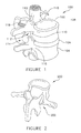
- FIG. 2 is a posterior, lateral perspective view of a vertebra
- FIG. 3 is a flowchart illustrative of the surgical methodology consistent with an embodiment of the present disclosure
- FIG. 4 is a view of pedicle screw extensions
- FIG. 5 is a perspective view of a part consistent with an embodiment of the present disclosure.
- FIG. 6 is a perspective view of a speculum consistent with an embodiment of the present disclosure.
- FIG. 7 is a perspective view of a portion of a retractor system consistent with an embodiment of the present disclosure.
- FIG. 7A is a perspective view of a portion of a retractor system with first and second posts;
- FIG. 7B is a perspective view of a portion of a retractor system with a shroud that inhibits soft tissue from interfering with the surgical area;
- FIG. 8 is a proximal plan view of the retractor system of FIG. 7 ;
- FIG. 8A is a proximal plan view of the retractor system of FIG. 7 with the cover removed;
- FIG. 8B is an enlarged view of a portion of FIG. 8A ;
- FIG. 8C is a view of the slides of FIG. 8 in a substantially closed position
- FIG. 8D is a view of the slides of FIG. 8 in a substantially opened position
- FIG. 9 is an illustration of a surgical kit containing the retractor system of FIG. 7 ;
- FIG. 10 is a view of a patient prior to insertion of the retractor system of FIG. 7 ;
- FIG. 11 is a perspective view of a spine accessed by a Jamshidi needle
- FIG. 12 is a perspective view of a spine accessed by a series of dilators of the retractor system of FIGS. 7 and 9 ;
- FIG. 13 is a perspective view of a post of the retractor system of FIGS. 7 and 9 ;
- FIG. 14 is an elevation view of the post of FIG. 13 ;
- FIG. 15 is a perspective view of the post of FIG. 13 showing an anchor at an alternative angle
- FIG. 16 is an elevation view of the post of FIG. 13 and a driver of the retractor system of FIGS. 7 and 9 ;
- FIG. 16A is an exploded view of the post and driver of FIG. 16 ;
- FIG. 17 is a view of the post and driver of FIG. 16 assembled together
- FIG. 18 is a perspective view of a spine accessed by the post, driver, and a T-handle inserter of the retractor system of FIGS. 7 and 9 ;
- FIG. 19 is a perspective view of a spine accessed by the post and a pressure core
- FIG. 20 is a perspective view of a spine accessed by the post
- FIG. 21 is an elevation view showing blades coupled to slides of the retractor system of FIGS. 7 and 9 ;
- FIG. 22 is a perspective view of the assembly of FIG. 21 including a driver engaged therewith;
- FIG. 23 is an elevation view of an inserter of the retractor system of FIGS. 7 and 9 ;
- FIG. 24 is a perspective view of the retractor coupled to the inserter
- FIG. 25 is a perspective view of the retractor system of FIGS. 7 and 9 being coupled to the spine;
- FIG. 26 is a perspective view of the retractor system of FIGS. 7 and 9 coupled to the spine and the inserter;
- FIG. 27 is a perspective view of the retractor system of FIGS. 7 and 9 coupled to the spine in a closed configuration
- FIG. 28 is a perspective view of the retractor system of FIGS. 7 and 9 coupled to the spine in an opened configuration
- FIGS. 29-37 are perspective views at different orientations of the retractor system of FIGS. 7 and 9 coupled to the spine in the opened configuration;
- FIG. 38-40 are perspective views of removing the retractor system
- FIG. 41 is a perspective view of a light source of the retractor system of FIGS. 7 and 9 ;
- FIG. 42 is a perspective view of the light source coupled to the retractor of FIGS. 7 and 9 ;
- FIG. 43 is a perspective view of a snakearm of the retractor system of FIGS. 7 and 9 ;
- FIG. 44 is a perspective view of a snake arm adapter coupled to the retractor of FIGS. 7 and 9 .
- FIG. 1 shows an anterior, lateral perspective view of a spinal segment 100 .
- Spinal segment 100 includes superior vertebrae 102 , inferior vertebrae 104 , and an intervertebral disc 106 .
- a spinal cord 108 has a number of nerves 110 extending from the spinal cord 108 . As can be seen, the nerves 110 generally extend through the neural foramen 112 close to a pedicle of superior vertebrae 102 .
- FIG. 2 shows another view of the spinal segment 100 with a view of the lamina 202 and the facet 114 .
- a rod may be coupled to superior vertebrae 102 and inferior vertebrae 104 to facilitate fusion.
- a pedicle screw may be threaded into the vertebral body, such as pedicle screw 118 shown threaded into the pedicle of superior pedicle 102 in FIG. 1 .
- pedicle screw 118 shown threaded into the pedicle of superior pedicle 102 in FIG. 1 .
- two (2) pedicle screws 118 are used on each vertebral body although only one is shown on the superior vertebrae for convenience.
- rods are connected to pedicle screws 118 in a conventional manner, not shown or further described as it is generally well known in the art.
- the technology of the present application provides orientation and safety features for the surgeon which may reduce the time the surgeon needs to enter the space associated with intervertebral disc 106 and reduce the potential for injury to spinal cord 108 and/or nerves 110 .
- the technology of the present application provides a platform to allow the surgeon the ability to remove bone associated with the vertebral body and access the disc space in a reproducible and standardized fashion.
- the technology described herein may reduce the overall surgical time, provide the ability for surgeons to avoid damage to the patient, and ultimately lead to increased acceptance of minimally invasive fusion technology, for example.
- flowchart 300 relates only to use of the exemplary embodiment and does not address conventional surgical procedures, such as for a TLIF procedure.
- the surgeon may use conventional methods to cannulate the inferior pedicle 116 , step 302 .
- the surgeon may use conventional guide wires and conventional surgical navigation technology to locate the inferior pedicle 116 .
- a dilator placed over the guide wire provides access to the pedicle, step 304 .
- a pedicle screw 118 and extender 402 see FIG.
- inferior pedicle 116 may be threaded into inferior pedicle 116 . If a pedicle screw 118 and extender 402 are not used, an alternative structure may be placed that locates the pedicle and provides a track or stable platform. In alternative embodiments, the retractor systems described in conjunction with FIGS. 7-44 may be used to locate and attach to the pedicle.
- bone cutter 500 b is attached to bone cutter guide 500 a as a unitary member.
- Part 500 has a track or groove 502 that can clamp on, for example, extender 402 .
- Part 500 movably couples to extender 402 or some similar structure. The movable connection could be slidable, geared, rotational, or the like.
- Part 500 would be moved along extender 402 using the track or groove 502 until bone cutter 500 b abuts a portion of the vertebral body, step 306 .
- bone cutter 500 b is a simple box shape. Other shapes are possible, such as, for example, a wedge shape, a circular shape, a conical shape, other random shapes, or the like.
- bone cutter 500 b may need to be angularly oriented.
- part 500 may have an angular orientation device 504 to align bone cutter 500 b with the portion of the vertebral body to be removed.
- Angular orientation device 504 may be a simple cam, hinge or the like. If angular orientation is necessary, the device is oriented as necessary, step 308 .
- the surgeon uses the bone cutter 500 b to remove portions of the vertebral body consistent with conventional surgical procedures, step 310 , such as, for example, the surgeon may remove a portion of the facet joint.
- Bone cutter 500 b may be shaped in a box shape as is conventional or other shapes, such as, circular, rectangular, triangular, other geometric or random shapes.
- Bone cutter 500 b is used to remove a portion of the vertebral body only as necessary. If bone cutter 500 b is hollow or has a through hole, bone cutter 500 b may remain in place, but is preferably removed, step 312 .
- a speculum 600 having a substantially flat portion 602 and handle 604 , is inserted into the disc annulus, step 312 .
- Flat portion 602 may terminate in a lip 606 . Once placed, speculum 600 is moved towards the superior vertebrae 102 .
- Flat portion 602 and, if provided, lip 606 push on nerve 608 (shown in phantom, which corresponds to nerve 110 ) and holds nerve 608 against the superior pedicle 102 .
- Underside 610 of speculum 600 provides a shield as the surgeon accesses the space associated with intervertebral disc 106 .
- speculum 600 may have a distractor 612 , which may take many shapes but is generally flat and long, similar to flat portion 602 .
- Distractor 612 may extend beyond flat portion 602 and terminate in a leading edge 614 .
- Leading edge 614 may pierce the disc annulus to provide a platform or base for the surgical sight.
- Speculum 600 may be placed to maintain separation of vertebral bodies to facilitate access to the space associated with intervertebral disc 106 .
- Distraction or separation of distractor 612 and flat portion 602 may be obtained by, for example, turning a cam 616 , a scissor operation, or the like.
- Other exemplary embodiments are illustrated in FIGS. 7-44 . These illustrations provide various device configurations and procedures in connection with a retractor system 700 for providing a surgical pathway to a spinal site using a pedicle guided retractor system.
- retractor system 700 may include an elongate member, such as a post 705 having a distal end 710 and a proximal end 715 .
- Distal end 710 of post 705 may have an anchor 1300 (see FIG. 13 ) to attach post 705 to a pedicle 2500 (see FIG. 25 ) of a vertebral body 2505 with respect to an intervertebral disc 2510 so as to be configured to facilitate surgical access to intervertebral disc 2510 between vertebral body 2515 and vertebral body 2505 .
- Post 705 may, in some embodiments, be or include the extender 402 (see FIG. 4 ).
- retractor system 700 is generally shown using a single post 705 to couple to an inferior pedicle 2500 , it is possible to provide a retractor system 700 such that the single post 705 is coupled to a superior pedicle as a matter of design choice, although it is believed that coupling the post 705 to the inferior pedicle provides improved access to the surgical area.
- retractor system 700 may comprise first and second posts 705 (see FIG. 7A .)
- the first post 705 may be coupled to the inferior pedicle and the second post 705 may be coupled to the superior pedicle.
- One advantage of using a first post and second post 705 would include providing a retractor system 700 that could operate to distract or compress the vertebrae as desired by the surgeon.
- Retractor system 700 may include a retractor body 720 having a collar 722 to adjustably attach retractor body 720 to post 705 between distal end 710 and proximal end 715 of post 705 .
- a pair of slides 725 may adjustably couple to retractor body 720 .
- Slides 725 may be configured for selective adjustment with respect to one another between a substantially closed position (see FIG. 8C ) and an opened position (see FIG. 8D ) with slides 725 further apart than the substantially closed position. Slides 725 may be adjustably coupled to retractor body 720 using a tongue and groove, slot and channel, or other adjustable connections as are generally known in the art.
- a pair of blades 730 may be mounted to slides 725 .
- Each one of blades 730 may have a proximal end 735 and a distal end 740 .
- a distance between proximal end 735 and distal end 740 of each one of blades 730 may be configured for displacing tissue for access to an intervertebral disc. Depending on the patient size and other factors, different length blades 730 can be selected and used.
- An attachment portion 745 may be positioned adjacent the proximal end 735 of each one of blades 730 for attaching one of slides 725 thereto.
- a geometry 750 of distal end 740 of each one of blades 730 may be provided for conforming to anatomy surrounding the pedicle (e.g., pedicle 2500 ).
- geometry 750 may include a region of blade 730 having diminished thickness or varying thickness.
- Geometry 750 may further or alternatively include a flat or curved distal edge of blade distal end 740 .
- shroud 752 may be expandable such that it can be fitted around, for example, the blades 730 prior to implanting the retractor system 700 into a surgical area and the shroud 752 expands as the blades move apart to establish the surgical area.
- the shroud 752 may be a relatively rigid shroud 752 that may be fitted about the body and post of the retractor system after the blades establish the surgical area.
- the shroud 752 may provide a generally constant diameter opening to the surgical site.
- the shroud 752 has a larger opening at the distal end (e.g., adjacent the disc space) than at the proximal end (e.g., outside the patient). Still further, the shroud 752 may be fitted about post 705 (or posts 705 ) and blades 730 .
- An example of an expandable shroud is contained in U.S. Pat. No. 7,056,321 titled “Method of Securing Vertebrae” issued to Pagliuca et al. on Jun. 6, 2006, at FIGS. 33-45 and corresponding text.
- U.S. Pat. No. 7,056,321 is incorporated herein by reference as if set out in full herein.
- a post tightening knob 755 may interoperate with collar 722 , which in turn adjusts the position of a protrusion 760 (see FIG. 8 ) within collar 722 .
- Protrusion 760 may provide a selective engagement to hold post 705 within collar 722 .
- One or more pitch/roll dials 765 may be provided in retractor body 720 to control the orientation of the retractor body 720 relative to the post 705 .
- a blade tightening screw 770 may be provided in communication with each one of slides 725 to selectively secure and release blades 730 from retractor body 720 .
- a slide lock 775 may be provided in communication with each one of slides 725 to selectively lock and release each of slides 725 with respect to retractor body 720 .
- slides 725 are engagingly coupled together in a manner which allows both slides 725 to be locked in place relative to one another with the use of a single slide lock 775 .
- one or more of pitch/roll dials 765 , blade tightening screw 770 , and slide lock 775 may include a ratchet adjustment for its respective operation. For example, and in an embodiment, rotating a Torx drive in a desired direction, such as towards a laser marked dot, operates to lock or fix the feature it controls. Rotating a Torx drive in a different or same desired direction, such as towards a laser marked circle, operates to unlock or release the feature it controls.
- one or more of pitch/roll dials 765 , blade tightening screw 770 , and slide lock 775 may include another adjustment mechanism for its respective operation.
- Kit 900 may contain one or more posts 705 , retractor body 720 , blades 730 , one or more T-handles 905 , a driver 910 for post 705 , a pressure core 915 for post 705 , one or more blade and retractor straight handle drivers 920 , an inserter 925 , a muscle spreader 930 , a muscle splitter 935 , a counter torque instrument 940 , a straight handle driver 945 , a turning rod 950 , a light source 4100 , and a snake arm connector 4300 .
- the type, quantity and location of components within kit 900 may vary from that depicted in FIG. 9 .
- blades 730 of varying lengths may be provided within kit 900 .
- a method may include the steps of establishing a soft tissue path with an incision to a vertebral disc, determining a location of an inferior pedicle, placing a k-wire at the inferior pedicle, dilating soft tissue adjacent the inferior pedicle, attaching a post to the inferior pedicle, choosing a pair of blades that match a depth indicated by the post, securing each one of the pair of blades to a retractor body, driving the blades into the incision and sliding the post through a collar of the retractor body, securing the retractor body to the post, and opening the blades to form a surgical opening to access a vertebral disc.
- FIGS. 10-40 illustrate various embodiments of methods of facilitating surgical access to a vertebral disc.
- a soft tissue path is established.
- a paraspinal approach such as a modified Wiltse approach
- an appropriate length skin and fascial incision may be made to establish a muscle plane path.
- the incision is approximately 35 mm in length, and is made approximately 40 mm from the midline.
- the pedicle location may be determined as indicated in FIG. 11 .
- an instrument such as a bone marrow biopsy needle (e.g., a Jamshidi needle) is used to locate and cannulate the inferior pedicle on the same side the TLIF will be performed.
- the inner stylus is removed and a K-wire 1100 is inserted to the appropriate depth using a T-handle inserter 905 .
- Soft tissue dilation may be performed using K-wire 1100 positioned in place. Keeping K-wire 1100 steady, concentric sized dilators 1200 (e.g., starter, second, third, and final dilators) are inserted over K-wire 1100 (see FIG. 12 ). Once the final dilator has been placed, which in some cases is the third dilator, all inner dilator tubes may be removed, leaving only the final dilator in place. This final dilator 1200 can maintain a working window for at least some of the following procedures.
- concentric sized dilators 1200 e.g., starter, second, third, and final dilators
- FIGS. 13-18 illustrate preparation and attachment of an elongate member such as a post 705 to a pedicle.
- Post 705 may form a polyaxial (e.g., FIG. 16A ) or mono axial (e.g., FIG. 17 ) joint 1305 with anchor 1300 .
- a collar 1320 is coupled to post 705 in a manner which secures anchor 1300 to post 705 while allowing rotational and pivoting movement of anchor 1300 .
- Collar 1320 may be coupled to post 705 by welding, adhesives, or other appropriate coupling techniques.
- Ribs 1310 may be provided on post 705 for interaction with protrusion 760 in collar 722 of the retractor body.
- ribs 1310 have numerical or other indicators so the height or location of attachment of collar 722 can be determined relative to anchor 1300 .
- Protrusion 760 may be selectively positioned in ribs 1310 by adjusting post tightening knob 755 .
- Driver 910 is slid or translated along a cannula of post 705 and attached into place, such as by threading. Coupling driver 910 to post 705 operates, in some embodiments, to lock the angular relationship between anchor 1300 and post 705 .
- anchor 1300 comprises a polyaxial joint which allows rotational and pivoting movement between anchor 1300 and post 705 .
- driver 910 has a distal portion which engages a proximal portion of anchor 1300 to prevent the rotational and/or pivoting movements of anchor 1300 .
- driver 910 and anchor 1300 may include, for example, a frictional relationship between two similarly curved or shaped surfaces (e.g., a spherical head of anchor 1300 and a matching concave distal end of driver 910 ), or may include a projection and detent relationship, or may use other engagement relationships. In this manner, driver 910 may be used to drive, screw, or otherwise insert anchor 1300 into the vertebral body.
- Post 705 and driver 910 are translated over K-wire 1100 , with a straight handle driver 945 , T-handle 905 or a similar device.
- Anchor 1300 (which may be configured as a post tap, such as a 4.5 mm or other length post tap) is then carefully driven into the pedicle.
- post 705 is driven into the pedicle, but does not bottom out against the pedicle or facet in order to prevent loss of polyaxial mobility with polyaxial joint 1305 .
- post 705 is backed out, such as by using about 2 or 3 turns of driver 945 or handle 905 .
- driver 910 is detached from post 705 , K-wire 1100 is pulled out or extracted, and dilator 1200 is removed.
- a pressure core 915 is placed or slid down into post 705 .
- Pressure core 915 may be tightened to post 705 , such as by finger tightening.
- post 705 is oriented such that ribs 1310 face away from the disc space. Properly positioned, post 705 should be secured to the pedicle but free to spin and pivot.
- retractor body 720 and blades 730 may be assembled together as described herein.
- a pair of blades 730 may be chosen that match the depth indicated by post 705 . This depth may be identified by the number on post 705 that appears just above the surface of the patient's skin.
- driver 920 which may be selected as a T15 Torx Driver 920
- each blade 730 may be secured in the orientation shown and into the corresponding slot in retractor body 720 .
- blade tightening screw 770 may be turned to help hold or lock blade 730 in place, with it being desirable to avoid over-tightening blade tightening screw 770 .
- Inserter 925 may be provided for manipulating and placing retractor body 720 along post 705 .
- Inserter 925 may grasp retractor body 720 with blades 730 closed and centered as illustrated in FIG. 24 .
- inserter 925 includes two arms 955 rotating about a pivot 960 and having opposing distal tips 965 .
- Distal tips 965 may engage retractor body 720 , and then are held in place using a lock mechanism 970 , depicted herein as a threaded nut and shaft arrangement although other locks may be used within the scope of the present disclosure.
- distal tips 965 engage slides 725 and/or blades 730 .
- Blades 730 may be slowly driven by retractor body 720 into the incision while confirming that post 705 slides through collar 722 of retractor body 720 as best illustrated in FIGS. 25 and 26 .
- one user hand engages the pedicle post 705
- the other user hand holds inserter 925 during insertion of blades 730 into the incision.
- FIGS. 25 and 26 have omitted certain portions of retractor system 700 .
- post tightening knob 755 also referred to as a locking nut
- FIGS. 27 and 28 depict an embodiment for separating or opening blades 730 apart from one another with a muscle spreader 930 .
- Other mechanisms also may be used for opening blades 730 .
- muscle spreader 930 is used to expand blades 730 .
- a muscle splitter 935 can be used if the incision does not allow proper expansion of blades 730 .
- retractor body 720 With blades 730 now in position, and the angle of retractor body 720 determined, retractor body 720 is restrained and driver 905 (or another driver) is used together with T30 Torx Drive T Handle 905 (or another handle) to secure pressure core 915 in post 705 as illustrated in FIG. 29 . In this manner, post 705 is secured relative to the inferior vertebrae, with pivoting and rotational movement restricted.
- retractor body 720 may be adjusted with respect to post 705 as illustrated in FIGS. 30 and 31 .
- roll/pitch dials 765 may be used to adjust the position of retractor body 720 .
- Unlocking pitch/roll dials 765 releases collar 722 , which allows retractor body 720 to swivel about post 705 .
- FIGS. 30 and 31 illustrate retractor body 720 moved from a first swivel angle to a second swivel angle with respect to post 705 .
- FIGS. 32-37 illustrate exemplary positioning of retractor system 700 for facetectomy for the TLIF, and where the insertion of the TLIF interbody may now be safely performed.
- geometry 750 of distal end 740 of blades 730 has a rising curve toward the superior end where post 705 is located. This geometry 750 allows the blades to closely conform to the surrounding tissue and features present at the surgical site.
- Retractor removal may include the use of driver 905 , and may include T30 Torx Drive T Handle 905 , to remove pressure core 915 from post 705 as illustrated in FIG. 38 .
- driver 920 such as a T25 Torx Driver
- blade tightening screw 770 may be released (such as by turning blade tightening screw 770 a quarter turn outwards) so as to close blades 730 .
- Post tightening knob 755 is turned to loosen or unlock, (e.g., a counterclockwise turning) until retractor body 720 may be removed from post 705 .
- FIG. 39 illustrates a step of removal of post 705 .
- Driver 910 may be reinserted into post 705 . It should be confirmed that the hex head fully seats in the spherical head of the tap, or other secure engagement between driver 910 and anchor 1300 . In some embodiments, the threaded portion of driver 910 will fully disappear once this is achieved. With driver 910 in place, a K-wire 1100 is inserted and post 705 is removed.
- a screw may be inserted using typical minimally invasive surgical (MIS) techniques. It should be appreciated that it may be necessary to reinsert the dilators for such a procedure or require the hole be re-tapped to a larger size.
- MIS minimally invasive surgical
- a light source 4100 is depicted as an accessory light source attachment to retractor body 720 .
- a light emitter 4105 may be positioned between blades 730 using an attachment bracket 4110 with threads 4115 for insertion into retractor body 720 .
- a shaft 4120 supports bracket 4110 and leads to light emitter 4105 .
- bracket 4110 on light source 4100 With blades 730 slightly open and bracket 4110 on light source 4100 positioned appropriately on shaft 4120 , light source 4100 can be moved or slid into place.
- a threaded hole in retractor body 720 can be aligned with the threads on bracket 4110 .
- Light source emitter 4105 may be positioned as needed and bracket 4110 can be tightened to shaft 4120 to secure light source emitter 4105 in a desired position.
- a snakearm connection 4300 may include a snakearm post 4305 for connection to a collar 722 of retractor body 720 and two prongs 4310 for connection to a snakearm.
- snakearm connection 4300 may be placed in the position shown, or facing an opposite direction.
- snakearm post 4305 may be extended down through collar 722 of the retractor and secure it by turning the post tightening knob 755 of retractor body 720 .
- a standard table snakearm can be used, and connected to the two exposed prongs 4310 of snakearm connection 4300 .
- a table snakearm can be used to hold retractor body 720 and blades 730 in a desired position.
- a table snakearm can be used as supplemental fixation of retractor body 720 and blades 730 in addition to post 705 .
Landscapes
- Health & Medical Sciences (AREA)
- Life Sciences & Earth Sciences (AREA)
- Surgery (AREA)
- Molecular Biology (AREA)
- General Health & Medical Sciences (AREA)
- Biomedical Technology (AREA)
- Heart & Thoracic Surgery (AREA)
- Medical Informatics (AREA)
- Nuclear Medicine, Radiotherapy & Molecular Imaging (AREA)
- Animal Behavior & Ethology (AREA)
- Engineering & Computer Science (AREA)
- Public Health (AREA)
- Veterinary Medicine (AREA)
- Oral & Maxillofacial Surgery (AREA)
- Orthopedic Medicine & Surgery (AREA)
- Dentistry (AREA)
- Pathology (AREA)
- Surgical Instruments (AREA)
- Prostheses (AREA)
Abstract
Description
Claims (17)
Priority Applications (2)
| Application Number | Priority Date | Filing Date | Title |
|---|---|---|---|
| US12/630,564 US8251902B2 (en) | 2005-10-17 | 2009-12-03 | Pedicle guided retractor system |
| US13/593,177 US8696558B1 (en) | 2005-10-17 | 2012-08-23 | Pedicle guided retractor system |
Applications Claiming Priority (3)
| Application Number | Priority Date | Filing Date | Title |
|---|---|---|---|
| US11/251,689 US20070118134A1 (en) | 2005-10-17 | 2005-10-17 | Surgical Tools and method to facilitate spinal surgery |
| US20095908P | 2008-12-05 | 2008-12-05 | |
| US12/630,564 US8251902B2 (en) | 2005-10-17 | 2009-12-03 | Pedicle guided retractor system |
Related Parent Applications (1)
| Application Number | Title | Priority Date | Filing Date |
|---|---|---|---|
| US11/251,689 Continuation-In-Part US20070118134A1 (en) | 2005-10-17 | 2005-10-17 | Surgical Tools and method to facilitate spinal surgery |
Related Child Applications (1)
| Application Number | Title | Priority Date | Filing Date |
|---|---|---|---|
| US13/593,177 Continuation US8696558B1 (en) | 2005-10-17 | 2012-08-23 | Pedicle guided retractor system |
Publications (2)
| Publication Number | Publication Date |
|---|---|
| US20100286486A1 US20100286486A1 (en) | 2010-11-11 |
| US8251902B2 true US8251902B2 (en) | 2012-08-28 |
Family
ID=43062748
Family Applications (2)
| Application Number | Title | Priority Date | Filing Date |
|---|---|---|---|
| US12/630,564 Active 2026-05-06 US8251902B2 (en) | 2005-10-17 | 2009-12-03 | Pedicle guided retractor system |
| US13/593,177 Expired - Fee Related US8696558B1 (en) | 2005-10-17 | 2012-08-23 | Pedicle guided retractor system |
Family Applications After (1)
| Application Number | Title | Priority Date | Filing Date |
|---|---|---|---|
| US13/593,177 Expired - Fee Related US8696558B1 (en) | 2005-10-17 | 2012-08-23 | Pedicle guided retractor system |
Country Status (1)
| Country | Link |
|---|---|
| US (2) | US8251902B2 (en) |
Cited By (2)
| Publication number | Priority date | Publication date | Assignee | Title |
|---|---|---|---|---|
| US8727975B1 (en) | 2013-05-10 | 2014-05-20 | Spine Wave, Inc. | Retractor for use in spinal surgery |
| US10194960B1 (en) | 2015-12-03 | 2019-02-05 | Nuvasive, Inc. | Spinal compression instrument and related methods |
Families Citing this family (10)
| Publication number | Priority date | Publication date | Assignee | Title |
|---|---|---|---|---|
| US9615818B2 (en) | 2010-09-20 | 2017-04-11 | DePuy Synthes Products, Inc. | Spinal access retractor |
| US9907582B1 (en) | 2011-04-25 | 2018-03-06 | Nuvasive, Inc. | Minimally invasive spinal fixation system and related methods |
| US20140058446A1 (en) * | 2011-09-28 | 2014-02-27 | Avi Bernstein | Spinal implant system |
| US9271711B2 (en) | 2012-03-30 | 2016-03-01 | DePuy Synthes Products, Inc. | Methods and devices for tissue retraction |
| US8821394B2 (en) | 2012-03-30 | 2014-09-02 | DePuy Synthes Products, LLC | Methods and devices for tissue retraction |
| AU2015229719B2 (en) | 2014-03-10 | 2017-04-06 | Stryker Corporation | Limb positioning system |
| US9951904B2 (en) | 2015-03-24 | 2018-04-24 | Stryker Corporation | Rotatable seat clamps for rail clamp |
| JP2018517507A (en) * | 2015-06-11 | 2018-07-05 | ハウメディカ・オステオニクス・コーポレイション | Spinal fixation targeting system and method for posterior spine surgery |
| EP3713499B1 (en) * | 2017-11-22 | 2022-04-20 | Devicor Medical Products, Inc. | Adjustable targeting set for mri guided biopsy procedure |
| US11259940B2 (en) | 2019-06-28 | 2022-03-01 | Mis Spine Ip, Llc | Systems and methods for percutaneous spinal interbody fusion (PSIF) |
Citations (50)
| Publication number | Priority date | Publication date | Assignee | Title |
|---|---|---|---|---|
| US5728046A (en) | 1995-06-23 | 1998-03-17 | Aesculap Ag | Surgical retractor |
| US5885293A (en) | 1997-03-03 | 1999-03-23 | Innovasive Devices, Inc. | Apparatus and method for cutting a surface at a repeatable angle |
| US5961522A (en) | 1997-11-10 | 1999-10-05 | Mehdizadeh; Hamid M. | Laminectomy chisel and guide apparatus |
| US20020013514A1 (en) | 2000-04-14 | 2002-01-31 | Brau Salvador A. | Surgical retractor and related surgical approach to access the anterior lumbar region |
| US20030199874A1 (en) | 2001-03-01 | 2003-10-23 | Michelson Gary K. | Dynamic lordotic guard with movable extensions for creating an implantation space posteriorly in the lumbar spine and method for use thereof |
| US20040116777A1 (en) | 2002-12-13 | 2004-06-17 | Jeffrey Larson | Guided retractor and methods of use |
| US20040220567A1 (en) | 2003-02-12 | 2004-11-04 | Sdgi Holdings, Inc. | Instruments and methods for aligning implants for insertion |
| US20040243130A1 (en) | 2002-10-11 | 2004-12-02 | Spineco, Inc., An Ohio Corporation | Electro-stimulation and medical delivery device |
| US20050080418A1 (en) | 2001-10-30 | 2005-04-14 | Simonson Robert E. | Instruments and methods for minimally invasive spine surgery |
| US20050080320A1 (en) | 2003-08-14 | 2005-04-14 | Lee Andrew Max | Multiple-blade retractor |
| US20050090822A1 (en) | 2003-10-24 | 2005-04-28 | Dipoto Gene | Methods and apparatus for stabilizing the spine through an access device |
| US20050137461A1 (en) | 2003-12-18 | 2005-06-23 | Depuy Spine, Inc. | Telescoping blade assembly and instruments for adjusting an adjustable blade |
| US20050149035A1 (en) | 2003-10-17 | 2005-07-07 | Nuvasive, Inc. | Surgical access system and related methods |
| US20050159651A1 (en) | 2003-12-18 | 2005-07-21 | Depuy Spine, Inc. | Surgical retractor systems and illuminated cannulae |
| US20050192575A1 (en) | 2004-02-20 | 2005-09-01 | Pacheco Hector O. | Method of improving pedicle screw placement in spinal surgery |
| US20050215862A1 (en) | 2003-11-26 | 2005-09-29 | Jeffrey Larson | Guided retractor and methods of use |
| US20050215866A1 (en) | 2004-03-25 | 2005-09-29 | Depuy Spine, Inc. | Surgical retractor positioning device |
| US20050273114A1 (en) | 2004-05-07 | 2005-12-08 | Novak Vincent P | Open wedge osteotomy system and surgical method |
| US20050273167A1 (en) | 2004-06-02 | 2005-12-08 | Triplett Daniel J | Surgical measurement and resection framework |
| US20060025863A1 (en) | 2004-07-27 | 2006-02-02 | Lamprich Lonnie J | Spinal disc prosthesis and methods |
| US20060052672A1 (en) | 2004-09-09 | 2006-03-09 | Landry Michael E | Surgical retraction apparatus method of use |
| US7014608B2 (en) | 2002-12-13 | 2006-03-21 | Synthes Spine Company, Lp | Guided retractor and methods of use |
| US20060069315A1 (en) | 2003-09-25 | 2006-03-30 | Patrick Miles | Surgical access system and related methods |
| US20060074445A1 (en) | 2004-09-29 | 2006-04-06 | David Gerber | Less invasive surgical system and methods |
| US20060106416A1 (en) | 2004-10-29 | 2006-05-18 | Douglas Raymond | Expandable ports and methods for minimally invasive surgery |
| US20060149273A1 (en) | 2004-12-06 | 2006-07-06 | Axiomed Spine Corporation | Method and apparatus for replacing a spinal disc |
| US20060155170A1 (en) | 2002-12-13 | 2006-07-13 | Synthes Spine Company, Lp | Guided retractor and methods of use |
| US20060195107A1 (en) | 2005-02-02 | 2006-08-31 | Jones Bryan S | Ultrasonic cutting device |
| US20060224045A1 (en) | 2005-03-31 | 2006-10-05 | Depuy Spine, Inc. | Integrated access device and light source for surgical procedures |
| US20060224044A1 (en) | 2005-03-31 | 2006-10-05 | Depuy Spine, Inc. | Surgical retractors and methods of use |
| US20060235338A1 (en) | 2005-03-07 | 2006-10-19 | Hector Pacheco | System and methods for improved access to vertebral bodies for kyphoplasty, vertebroplasty, vertebral body biopsy or screw placement |
| US7156805B2 (en) | 2003-03-31 | 2007-01-02 | Depuy Spine, Inc. | Surgical retractor |
| US20070021656A1 (en) | 2005-01-07 | 2007-01-25 | Stryker Spine | Three-prong retractor with elastomeric sheath |
| US20070038033A1 (en) | 2005-04-25 | 2007-02-15 | Depuy Spine, Inc. | Cassette based surgical retractor |
| US7182729B2 (en) | 2003-09-18 | 2007-02-27 | Stryker Spine | Surgical retractor with removable scissor arms |
| US20070100212A1 (en) | 2004-10-08 | 2007-05-03 | Nuvasive, Inc. | Surgical access system and related methods |
| US20070156024A1 (en) | 2006-01-04 | 2007-07-05 | William Frasier | Surgical Retractors and Methods of Minimally Invasive Surgery |
| US20070156026A1 (en) | 2006-01-04 | 2007-07-05 | William Frasier | Surgical access devices and methods of minimally invasive surgery |
| US20070156025A1 (en) | 2006-01-04 | 2007-07-05 | Connie Marchek | Surgical retractors and methods of minimally invasive surgery |
| US20070208228A1 (en) | 2006-03-01 | 2007-09-06 | Nicholas Pavento | Surgical retractors and methods of minimally invasive surgery |
| US20070208227A1 (en) | 2002-07-11 | 2007-09-06 | Nuvasive, Inc. | Surgical access system and related methods |
| US20070276191A1 (en) | 2006-05-26 | 2007-11-29 | Sean Selover | Illuminated surgical access system including a surgical access device and integrated light emitter |
| US20070282171A1 (en) | 2006-06-06 | 2007-12-06 | Edward Karpowicz | Surgical Retractor System |
| US20080021285A1 (en) * | 2006-01-04 | 2008-01-24 | Anne Drzyzga | Surgical retractor for use with minimally invasive spinal stabilization systems and methods of minimally invasive surgery |
| US20080021284A1 (en) | 2006-07-19 | 2008-01-24 | Zimmer Spine, Inc. | Surgical access system and method of using the same |
| US20080058606A1 (en) | 2002-10-08 | 2008-03-06 | Nuvasive, Inc. | Surgical access system and related methods |
| US20080097164A1 (en) | 2003-01-16 | 2008-04-24 | Nuvasive, Inc. | Surgical access system and related methods |
| US20080132766A1 (en) | 2006-12-05 | 2008-06-05 | Zimmer Spine, Inc. | Surgical Access System And Method Of Using Same |
| US20080214898A1 (en) | 2006-10-31 | 2008-09-04 | Lanx, Llc | Retractor system |
| US20080300465A1 (en) | 2005-09-08 | 2008-12-04 | Gregor Feigenwinter | Spine Retractor and Distractor Device |
Family Cites Families (1)
| Publication number | Priority date | Publication date | Assignee | Title |
|---|---|---|---|---|
| US20060106415A1 (en) * | 2004-11-12 | 2006-05-18 | Shlomo Gabbay | Apparatus to facilitate implantation |
-
2009
- 2009-12-03 US US12/630,564 patent/US8251902B2/en active Active
-
2012
- 2012-08-23 US US13/593,177 patent/US8696558B1/en not_active Expired - Fee Related
Patent Citations (55)
| Publication number | Priority date | Publication date | Assignee | Title |
|---|---|---|---|---|
| US5728046A (en) | 1995-06-23 | 1998-03-17 | Aesculap Ag | Surgical retractor |
| US5885293A (en) | 1997-03-03 | 1999-03-23 | Innovasive Devices, Inc. | Apparatus and method for cutting a surface at a repeatable angle |
| US5961522A (en) | 1997-11-10 | 1999-10-05 | Mehdizadeh; Hamid M. | Laminectomy chisel and guide apparatus |
| US20020013514A1 (en) | 2000-04-14 | 2002-01-31 | Brau Salvador A. | Surgical retractor and related surgical approach to access the anterior lumbar region |
| US20030199874A1 (en) | 2001-03-01 | 2003-10-23 | Michelson Gary K. | Dynamic lordotic guard with movable extensions for creating an implantation space posteriorly in the lumbar spine and method for use thereof |
| US20050080418A1 (en) | 2001-10-30 | 2005-04-14 | Simonson Robert E. | Instruments and methods for minimally invasive spine surgery |
| US20070208227A1 (en) | 2002-07-11 | 2007-09-06 | Nuvasive, Inc. | Surgical access system and related methods |
| US20080058606A1 (en) | 2002-10-08 | 2008-03-06 | Nuvasive, Inc. | Surgical access system and related methods |
| US20040243130A1 (en) | 2002-10-11 | 2004-12-02 | Spineco, Inc., An Ohio Corporation | Electro-stimulation and medical delivery device |
| US20040116777A1 (en) | 2002-12-13 | 2004-06-17 | Jeffrey Larson | Guided retractor and methods of use |
| US7014608B2 (en) | 2002-12-13 | 2006-03-21 | Synthes Spine Company, Lp | Guided retractor and methods of use |
| US20060155170A1 (en) | 2002-12-13 | 2006-07-13 | Synthes Spine Company, Lp | Guided retractor and methods of use |
| US20080097164A1 (en) | 2003-01-16 | 2008-04-24 | Nuvasive, Inc. | Surgical access system and related methods |
| US20040220567A1 (en) | 2003-02-12 | 2004-11-04 | Sdgi Holdings, Inc. | Instruments and methods for aligning implants for insertion |
| US7156805B2 (en) | 2003-03-31 | 2007-01-02 | Depuy Spine, Inc. | Surgical retractor |
| US20050080320A1 (en) | 2003-08-14 | 2005-04-14 | Lee Andrew Max | Multiple-blade retractor |
| US7182729B2 (en) | 2003-09-18 | 2007-02-27 | Stryker Spine | Surgical retractor with removable scissor arms |
| US20070123753A1 (en) | 2003-09-18 | 2007-05-31 | Stryker Spine | Surgical retractor with removable scissor arms |
| US7207949B2 (en) | 2003-09-25 | 2007-04-24 | Nuvasive, Inc. | Surgical access system and related methods |
| US20070198062A1 (en) | 2003-09-25 | 2007-08-23 | Nuvasive, Inc. | Surgical access system and related methods |
| US20060069315A1 (en) | 2003-09-25 | 2006-03-30 | Patrick Miles | Surgical access system and related methods |
| US20050149035A1 (en) | 2003-10-17 | 2005-07-07 | Nuvasive, Inc. | Surgical access system and related methods |
| US20050090822A1 (en) | 2003-10-24 | 2005-04-28 | Dipoto Gene | Methods and apparatus for stabilizing the spine through an access device |
| US20050215862A1 (en) | 2003-11-26 | 2005-09-29 | Jeffrey Larson | Guided retractor and methods of use |
| US20050137461A1 (en) | 2003-12-18 | 2005-06-23 | Depuy Spine, Inc. | Telescoping blade assembly and instruments for adjusting an adjustable blade |
| US20050159650A1 (en) | 2003-12-18 | 2005-07-21 | Depuy Spine, Inc. | Surgical methods and surgical kits |
| US20050159651A1 (en) | 2003-12-18 | 2005-07-21 | Depuy Spine, Inc. | Surgical retractor systems and illuminated cannulae |
| US20050192575A1 (en) | 2004-02-20 | 2005-09-01 | Pacheco Hector O. | Method of improving pedicle screw placement in spinal surgery |
| US7435219B2 (en) | 2004-03-25 | 2008-10-14 | Depuy Spine, Inc. | Surgical retractor positioning device |
| US20050215866A1 (en) | 2004-03-25 | 2005-09-29 | Depuy Spine, Inc. | Surgical retractor positioning device |
| US20050273114A1 (en) | 2004-05-07 | 2005-12-08 | Novak Vincent P | Open wedge osteotomy system and surgical method |
| US20050273167A1 (en) | 2004-06-02 | 2005-12-08 | Triplett Daniel J | Surgical measurement and resection framework |
| US20060025863A1 (en) | 2004-07-27 | 2006-02-02 | Lamprich Lonnie J | Spinal disc prosthesis and methods |
| US20060052672A1 (en) | 2004-09-09 | 2006-03-09 | Landry Michael E | Surgical retraction apparatus method of use |
| US20060074445A1 (en) | 2004-09-29 | 2006-04-06 | David Gerber | Less invasive surgical system and methods |
| US20070100212A1 (en) | 2004-10-08 | 2007-05-03 | Nuvasive, Inc. | Surgical access system and related methods |
| US20060106416A1 (en) | 2004-10-29 | 2006-05-18 | Douglas Raymond | Expandable ports and methods for minimally invasive surgery |
| US20060149273A1 (en) | 2004-12-06 | 2006-07-06 | Axiomed Spine Corporation | Method and apparatus for replacing a spinal disc |
| US20070021656A1 (en) | 2005-01-07 | 2007-01-25 | Stryker Spine | Three-prong retractor with elastomeric sheath |
| US20060195107A1 (en) | 2005-02-02 | 2006-08-31 | Jones Bryan S | Ultrasonic cutting device |
| US20060235338A1 (en) | 2005-03-07 | 2006-10-19 | Hector Pacheco | System and methods for improved access to vertebral bodies for kyphoplasty, vertebroplasty, vertebral body biopsy or screw placement |
| US20060224045A1 (en) | 2005-03-31 | 2006-10-05 | Depuy Spine, Inc. | Integrated access device and light source for surgical procedures |
| US20060224044A1 (en) | 2005-03-31 | 2006-10-05 | Depuy Spine, Inc. | Surgical retractors and methods of use |
| US20070038033A1 (en) | 2005-04-25 | 2007-02-15 | Depuy Spine, Inc. | Cassette based surgical retractor |
| US20080300465A1 (en) | 2005-09-08 | 2008-12-04 | Gregor Feigenwinter | Spine Retractor and Distractor Device |
| US20070156025A1 (en) | 2006-01-04 | 2007-07-05 | Connie Marchek | Surgical retractors and methods of minimally invasive surgery |
| US20080021285A1 (en) * | 2006-01-04 | 2008-01-24 | Anne Drzyzga | Surgical retractor for use with minimally invasive spinal stabilization systems and methods of minimally invasive surgery |
| US20070156026A1 (en) | 2006-01-04 | 2007-07-05 | William Frasier | Surgical access devices and methods of minimally invasive surgery |
| US20070156024A1 (en) | 2006-01-04 | 2007-07-05 | William Frasier | Surgical Retractors and Methods of Minimally Invasive Surgery |
| US20070208228A1 (en) | 2006-03-01 | 2007-09-06 | Nicholas Pavento | Surgical retractors and methods of minimally invasive surgery |
| US20070276191A1 (en) | 2006-05-26 | 2007-11-29 | Sean Selover | Illuminated surgical access system including a surgical access device and integrated light emitter |
| US20070282171A1 (en) | 2006-06-06 | 2007-12-06 | Edward Karpowicz | Surgical Retractor System |
| US20080021284A1 (en) | 2006-07-19 | 2008-01-24 | Zimmer Spine, Inc. | Surgical access system and method of using the same |
| US20080214898A1 (en) | 2006-10-31 | 2008-09-04 | Lanx, Llc | Retractor system |
| US20080132766A1 (en) | 2006-12-05 | 2008-06-05 | Zimmer Spine, Inc. | Surgical Access System And Method Of Using Same |
Non-Patent Citations (1)
| Title |
|---|
| Zimmer ARAS Retractor Instrumentation pamphlet from Zimmer Spine, 2007, www.zimmerspine.com, 19 pages. |
Cited By (5)
| Publication number | Priority date | Publication date | Assignee | Title |
|---|---|---|---|---|
| US8727975B1 (en) | 2013-05-10 | 2014-05-20 | Spine Wave, Inc. | Retractor for use in spinal surgery |
| US9498200B2 (en) | 2013-05-10 | 2016-11-22 | Spine Wave, Inc. | Method of retracting body tissue during surgery |
| US9545250B2 (en) | 2013-05-10 | 2017-01-17 | Spine Wave, Inc | Kit of parts for use in retracting body tissue |
| US10194960B1 (en) | 2015-12-03 | 2019-02-05 | Nuvasive, Inc. | Spinal compression instrument and related methods |
| US11006983B2 (en) | 2015-12-03 | 2021-05-18 | Nuvasive, Inc. | Spinal compression instrument and related methods |
Also Published As
| Publication number | Publication date |
|---|---|
| US20100286486A1 (en) | 2010-11-11 |
| US8696558B1 (en) | 2014-04-15 |
Similar Documents
| Publication | Publication Date | Title |
|---|---|---|
| US8696558B1 (en) | Pedicle guided retractor system | |
| EP1641403B1 (en) | Spinal stabilization implant | |
| US7306603B2 (en) | Device and method for percutaneous placement of lumbar pedicle screws and connecting rods | |
| US7188626B2 (en) | Instruments and methods for stabilization of bony structures | |
| US9161779B2 (en) | Minimally invasive retractor and methods of use | |
| US8231661B2 (en) | Systems and methods for minimally invasive facet fusion | |
| US8852210B2 (en) | Rigidly guided implant placement | |
| US7993378B2 (en) | Methods for percutaneous spinal surgery |
Legal Events
| Date | Code | Title | Description |
|---|---|---|---|
| AS | Assignment |
Owner name: LANX, INC., COLORADO Free format text: ASSIGNMENT OF ASSIGNORS INTEREST;ASSIGNORS:PARKER, JARED;THRAMANN, JEFFERY;FULTON, MICHAEL;SIGNING DATES FROM 20100510 TO 20100517;REEL/FRAME:024730/0948 |
|
| AS | Assignment |
Owner name: LANX, INC., COLORADO Free format text: ASSIGNMENT OF ASSIGNORS INTEREST;ASSIGNORS:PARKER, JARED;THRAMANN, JEFFERY;FULTON, MICHAEL;AND OTHERS;SIGNING DATES FROM 20100510 TO 20101102;REEL/FRAME:025338/0613 |
|
| STCF | Information on status: patent grant |
Free format text: PATENTED CASE |
|
| FEPP | Fee payment procedure |
Free format text: PAT HOLDER NO LONGER CLAIMS SMALL ENTITY STATUS, ENTITY STATUS SET TO UNDISCOUNTED (ORIGINAL EVENT CODE: STOL); ENTITY STATUS OF PATENT OWNER: LARGE ENTITY |
|
| AS | Assignment |
Owner name: BANK OF AMERICA, N.A., AS ADMINISTRATIVE AGENT, NO Free format text: SECURITY AGREEMENT;ASSIGNOR:LANX, INC.;REEL/FRAME:032086/0664 Effective date: 20140113 |
|
| AS | Assignment |
Owner name: LANX, INC., COLORADO Free format text: RELEASE OF SECURITY INTEREST IN PATENTS RECORDED AT REEL 032086/ FRAME 0664;ASSIGNOR:BANK OF AMERICA, N.A., AS ADMINISTRATIVE AGENT;REEL/FRAME:037155/0041 Effective date: 20150624 |
|
| FPAY | Fee payment |
Year of fee payment: 4 |
|
| AS | Assignment |
Owner name: ZIMMER BIOMET SPINE, INC., COLORADO Free format text: CHANGE OF NAME;ASSIGNOR:LANX, INC.;REEL/FRAME:037761/0231 Effective date: 20150730 |
|
| AS | Assignment |
Owner name: ZIMMER BIOMET SPINE, INC., COLORADO Free format text: CORRECTIVE ASSIGNMENT TO CORRECT THE REMOVE APPL. NO. 14/828,714 PREVIOUSLY RECORDED AT REEL: 037761 FRAME: 0231. ASSIGNOR(S) HEREBY CONFIRMS THE CHANGE OF NAME;ASSIGNOR:LANX, INC.;REEL/FRAME:038951/0064 Effective date: 20150730 |
|
| MAFP | Maintenance fee payment |
Free format text: PAYMENT OF MAINTENANCE FEE, 8TH YEAR, LARGE ENTITY (ORIGINAL EVENT CODE: M1552); ENTITY STATUS OF PATENT OWNER: LARGE ENTITY Year of fee payment: 8 |
|
| AS | Assignment |
Owner name: JPMORGAN CHASE BANK, N.A., AS ADMINISTRATIVE AGENT, NEW YORK Free format text: SECURITY INTEREST;ASSIGNORS:BIOMET 3I, LLC;EBI, LLC;ZIMMER BIOMET SPINE, INC.;AND OTHERS;REEL/FRAME:059293/0213 Effective date: 20220228 |
|
| AS | Assignment |
Owner name: CERBERUS BUSINESS FINANCE AGENCY, LLC, NEW YORK Free format text: GRANT OF A SECURITY INTEREST -- PATENTS;ASSIGNORS:ZIMMER BIOMET SPINE, LLC;EBI, LLC;REEL/FRAME:066970/0806 Effective date: 20240401 |
|
| AS | Assignment |
Owner name: ZIMMER BIOMET SPINE, LLC (F/K/A ZIMMER BIOMET SPINE, INC.), COLORADO Free format text: RELEASE BY SECURED PARTY;ASSIGNOR:JPMORGAN CHASE BANK, N.A.;REEL/FRAME:066973/0833 Effective date: 20240401 Owner name: EBI, LLC, NEW JERSEY Free format text: RELEASE BY SECURED PARTY;ASSIGNOR:JPMORGAN CHASE BANK, N.A.;REEL/FRAME:066973/0833 Effective date: 20240401 |
|
| FEPP | Fee payment procedure |
Free format text: MAINTENANCE FEE REMINDER MAILED (ORIGINAL EVENT CODE: REM.); ENTITY STATUS OF PATENT OWNER: LARGE ENTITY |